Embed Size (px)
Citation preview
Gauge ConsolesTECHNICAL SUPPORT
APEKS MARINE EQUIPMENT LTD, NEPTUNE WAY, BLACKBURN, LANCASHIRE. BB1 2BTTel: 0044 (0) 1254 692200 Fax: 0044 (0) 1254 692211 E-mail: [email protected] Web: www.apeks.co.uk
MAINTENANCE MANUAL FORCOMPETENT TECHNICIANS
Document No. AP 5929Issue 126/11/09
2
Gauge Consoles Maintenance Manual
3
Gauge Consoles Maintenance Manual
Change No.
Change Request No.
Description & Comments: Change Date
New Issue No.
Changed By:
Approved By:
AMENDMENTS RECORD:
Amendments and approval of this document can only be carried out by the relevant people listed on the Approved list of signatures, which is listed in the Apeks Quality Manual. To instigate a change, a Task / Change request form, (Form No. ‘DESI/10002’), must be completed and passed to the relevant person(s) for approval which are listed on the Approved List of Signatures. When approval has been granted and recoreded this table can then be completed and the document up issued.
2
Gauge Consoles Maintenance Manual
3
Gauge Consoles Maintenance Manual
ContentsCOPYRIGHT NOTICE............................................................................................................................................... 4INTRODUCTION....................................................................................................................................................... 4WARNINGS, CAUTIONS & NOTES ......................................................................................................................... 4SCHEDULED SERVICE ........................................................................................................................................... 4GENERAL GUIDELINES .......................................................................................................................................... 4GENERAL CONVENTIONS...................................................................................................................................... 5DISASSEMBLY PROCEDURES............................................................................................................................... 5REASSEMBLY PROCEDURES................................................................................................................................ 8TESTING PROCEDURE......................................................................................................................................... 10TABLE 1 - TROUBLSHOOTING GUIDE................................................................................................................. 11TABLE 2 - RECOMMENDED TOOL LIST............................................................................................................... 12TABLE 3 - RECOMMENDED LUBRICANTS AND CLEANERS ............................................................................ 13CLEANING AND LUBRICATION PROCEDURE .................................................................................................... 14TABLE 4 -TORQUE SPECIFICATIONS.................................................................................................................. 15TABLE 5 - TEST BENCH SPECIFICATIONS ......................................................................................................... 15 EXPLODED PARTS DRAWING............................................................................................................................. 16
4
Gauge Consoles Maintenance Manual
5
Gauge Consoles Maintenance Manual
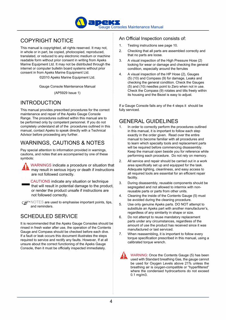
An Official Inspection consists of:1. Testing instructions see page 10.2. Checking that all parts are assembled correctly and
that no parts are loose.3. A visual inspection of the High Pressure Hose (2)
looking for wear or damage and checking the general condition, especially around the ferrules
4. A visual inspection of the HP Hose (2), Gauges (5) (10) and Compass (9) for damage, Leaks and checking the general condition. Check the Gauges (5) and (10) needles point to Zero when not in use. Check the Compass (9) rotates and tilts freely within its housing and the Bezel is easy to adjust.
If a Gauge Console fails any of the 4 steps it should be fully serviced.
GENERAL GUIDELINES1. In order to correctly perform the procedures outlined
in this manual, it is important to follow each step exactly in the order given. Read over the entire manual to become familiar with all procedures and to learn which specialty tools and replacement parts will be required before commencing disassembly. Keep the manual open beside you for reference while performing each procedure. Do not rely on memory.
2. All service and repair should be carried out in a work area specifically set up and equipped for the task. Adequate lighting, cleanliness, and easy access to all required tools are essential for an efficient repair facility.
3. During disassembly, reusable components should be segregated and not allowed to intermix with non-reusable parts or parts from other units.
4. Cleaning the inside of the Contents Gauge (5) must be avoided during the cleaning procedure.
5. Use only genuine Apeks parts. DO NOT attempt to substitute an Apeks part with another manufacturer’s, regardless of any similarity in shape or size.
6. Do not attempt to reuse mandatory replacement parts under any circumstances, regardless of the amount of use the product has received since it was manufactured or last serviced.
7. When reassembling, it is important to follow every torque specification prescribed in this manual, using a calibrated torque wrench.
COPYRIGHT NOTICEThis manual is copyrighted, all rights reserved. It may not, in whole or in part, be copied, photocopied, reproduced, translated, or reduced to any electronic medium or machine readable form without prior consent in writing from Apeks Marine Equipment Ltd. It may not be distributed through the internet or computer bulletin board systems without prior consent in from Apeks Marine Equipment Ltd.
©2010 Apeks Marine Equipment Ltd.
Gauge Console Maintenance Manual
(AP5929 Issue 1)
INTRODUCTIONThis manual provides prescribed procedures for the correct maintenance and repair of the Apeks Gauge Console Range. The procedures outlined within this manual are to be performed only by competent personnel. If you do not completely understand all of the procedures outlined in this manual, contact Apeks to speak directly with a Technical Advisor before proceeding any further.
WARNINGS, CAUTIONS & NOTESPay special attention to information provided in warnings, cautions, and notes that are accompanied by one of these symbols:
WARNINGS indicate a procedure or situation that may result in serious injury or death if instructions are not followed correctly.
CAUTIONS indicate any situation or technique that will result in potential damage to the product, or render the product unsafe if instructions are not followed correctly.
NOTES are used to emphasise important points, tips, and reminders.
SCHEDULED SERVICEIt is recommended that the Apeks Gauge Consoles should be rinsed in fresh water after use, the operation of the Contents Gauge and Compass should be checked before each dive. If a fault or leak occurs this document illustrates the steps required to service and rectify any faults. However, If at all unsure about the correct functioning of the Apeks Gauge Console, then it must be officially inspected immediately.
WARNING: Once the Contents Gauge (5) has been used with Standard breathing Gas, the gauge cannot be used for Oxygen Levels above 21% unless the breathing air is oxygen-compatible or “hyperfiltered” where the condensed hydrocarbons do not exceed 0.1 mg/m3.
4
Gauge Consoles Maintenance Manual
5
Gauge Consoles Maintenance Manual
Pinch MethodPress upwards on sides of ‘O’
Ring to create a protrusion. Grab ‘O’ Ring or insert
‘O’ Ring tool at protrusion.
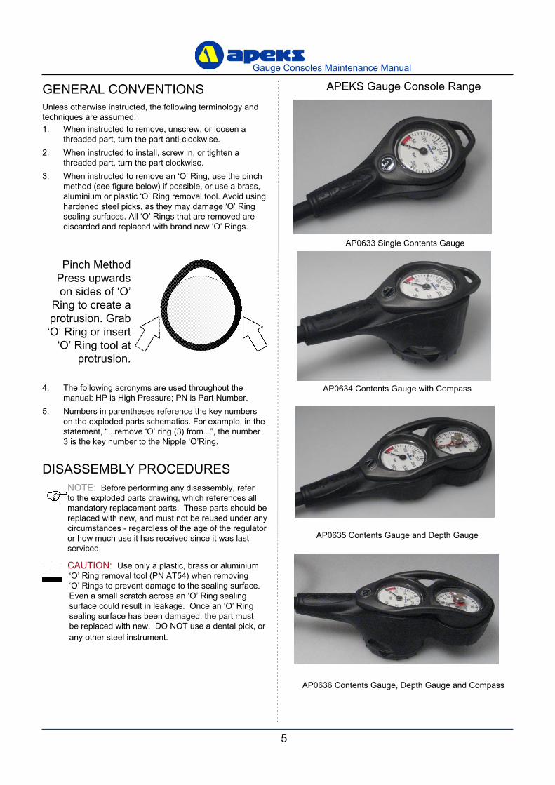
GENERAL CONVENTIONSUnless otherwise instructed, the following terminology and techniques are assumed:1. When instructed to remove, unscrew, or loosen a
threaded part, turn the part anti-clockwise.2. When instructed to install, screw in, or tighten a
threaded part, turn the part clockwise.3. When instructed to remove an ‘O’ Ring, use the pinch
method (see figure below) if possible, or use a brass, aluminium or plastic ‘O’ Ring removal tool. Avoid using hardened steel picks, as they may damage ‘O’ Ring sealing surfaces. All ‘O’ Rings that are removed are discarded and replaced with brand new ‘O’ Rings.
4. The following acronyms are used throughout the manual: HP is High Pressure; PN is Part Number.
5. Numbers in parentheses reference the key numbers on the exploded parts schematics. For example, in the statement, “...remove ‘O’ ring (3) from...”, the number 3 is the key number to the Nipple ‘O’Ring.
DISASSEMBLY PROCEDURES NOTE: Before performing any disassembly, refer
to the exploded parts drawing, which references all mandatory replacement parts. These parts should be replaced with new, and must not be reused under any circumstances - regardless of the age of the regulator or how much use it has received since it was last serviced.
CAUTION: Use only a plastic, brass or aluminium ‘O’ Ring removal tool (PN AT54) when removing ‘O’ Rings to prevent damage to the sealing surface. Even a small scratch across an ‘O’ Ring sealing surface could result in leakage. Once an ‘O’ Ring sealing surface has been damaged, the part must be replaced with new. DO NOT use a dental pick, or any other steel instrument.
AP0633 Single Contents Gauge
AP0634 Contents Gauge with Compass
AP0635 Contents Gauge and Depth Gauge
AP0636 Contents Gauge, Depth Gauge and Compass
APEKS Gauge Console Range
6
Gauge Consoles Maintenance Manual
7
Gauge Consoles Maintenance Manual
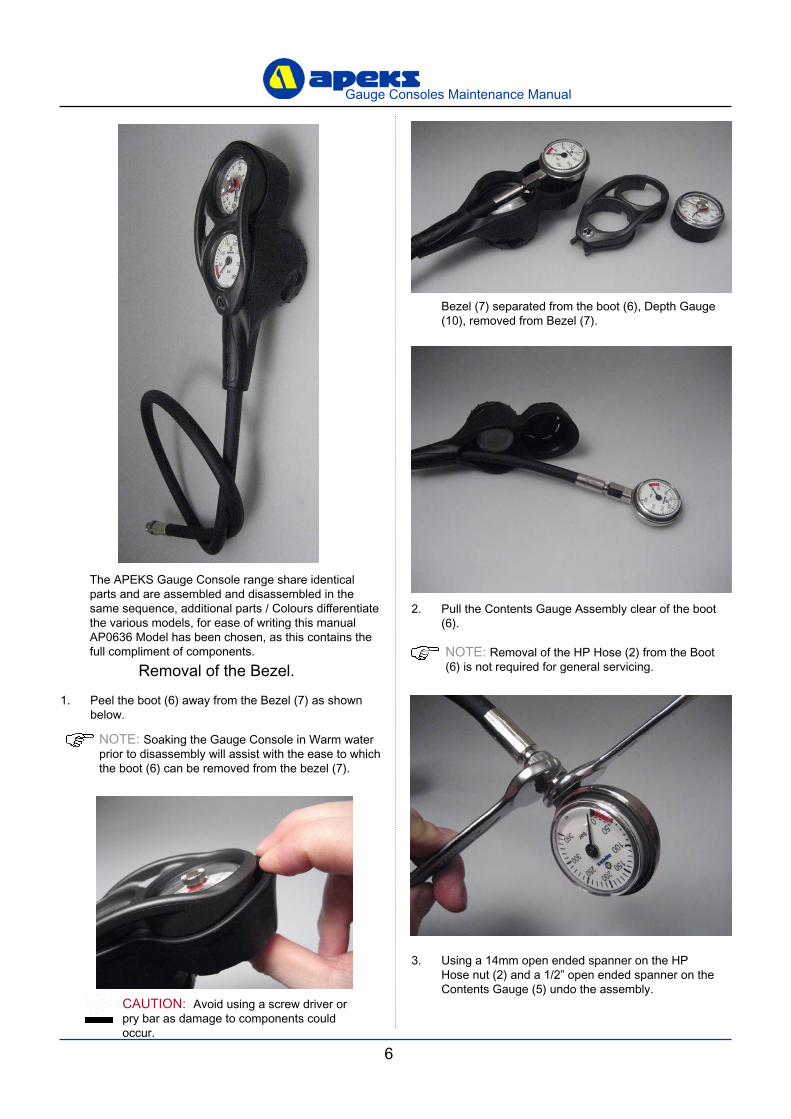
Bezel (7) separated from the boot (6), Depth Gauge (10), removed from Bezel (7).
1. Peel the boot (6) away from the Bezel (7) as shown below.
Removal of the Bezel.
NOTE: Soaking the Gauge Console in Warm water prior to disassembly will assist with the ease to which the boot (6) can be removed from the bezel (7).
CAUTION: Avoid using a screw driver or pry bar as damage to components could occur.
The APEKS Gauge Console range share identical parts and are assembled and disassembled in the same sequence, additional parts / Colours differentiate the various models, for ease of writing this manual AP0636 Model has been chosen, as this contains the full compliment of components.
2. Pull the Contents Gauge Assembly clear of the boot (6).
NOTE: Removal of the HP Hose (2) from the Boot (6) is not required for general servicing.
3. Using a 14mm open ended spanner on the HP Hose nut (2) and a 1/2” open ended spanner on the Contents Gauge (5) undo the assembly.
6
Gauge Consoles Maintenance Manual
7
Gauge Consoles Maintenance Manual
This Ends Disassembly For General Service
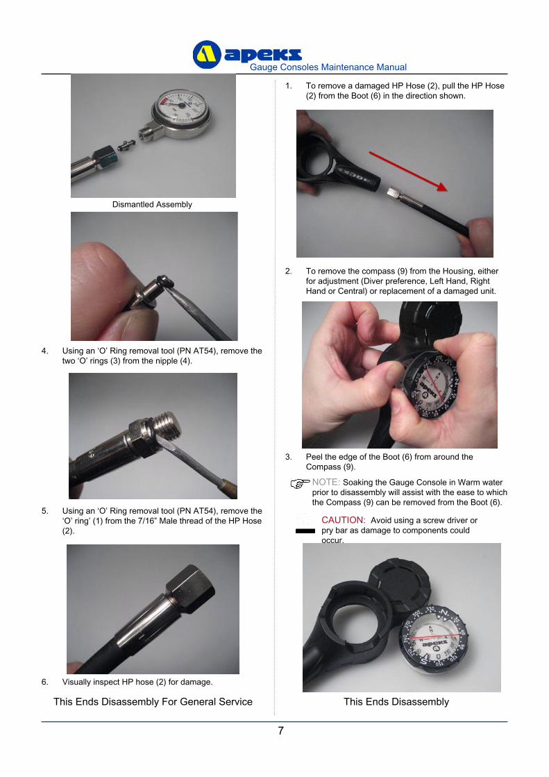
4. Using an ‘O’ Ring removal tool (PN AT54), remove the two ‘O’ rings (3) from the nipple (4).
Dismantled Assembly
5. Using an ‘O’ Ring removal tool (PN AT54), remove the ‘O’ ring’ (1) from the 7/16” Male thread of the HP Hose (2).
6. Visually inspect HP hose (2) for damage.
NOTE: Soaking the Gauge Console in Warm water prior to disassembly will assist with the ease to which the Compass (9) can be removed from the Boot (6).
CAUTION: Avoid using a screw driver or pry bar as damage to components could occur.
This Ends Disassembly
1. To remove a damaged HP Hose (2), pull the HP Hose (2) from the Boot (6) in the direction shown.
3. Peel the edge of the Boot (6) from around the Compass (9).
2. To remove the compass (9) from the Housing, either for adjustment (Diver preference, Left Hand, Right Hand or Central) or replacement of a damaged unit.
8
Gauge Consoles Maintenance Manual
9
Gauge Consoles Maintenance Manual
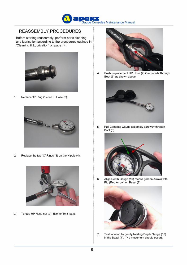
REASSEMBLY PROCEDURESBefore starting reassembly, perform parts cleaning and lubrication according to the procedures outlined in ‘Cleaning & Lubrication’ on page 14.
1. Replace ‘O’ Ring (1) on HP Hose (2).
2. Replace the two ‘O’ Rings (3) on the Nipple (4).
3. Torque HP Hose nut to 14Nm or 10.3 lbs/ft.
4. Push (replacement HP Hose (2) if reqiured) Through Boot (6) as shown above.
5. Pull Contents Gauge assembly part way through Boot (6).
6. Align Depth Gauge (10) recess (Green Arrow) with Pip (Red Arrow) on Bezel (7).
7. Test location by gently twisting Depth Gauge (10) in the Bezel (7). (No movement should occur).
8
Gauge Consoles Maintenance Manual
9
Gauge Consoles Maintenance Manual
This Ends Reassembly
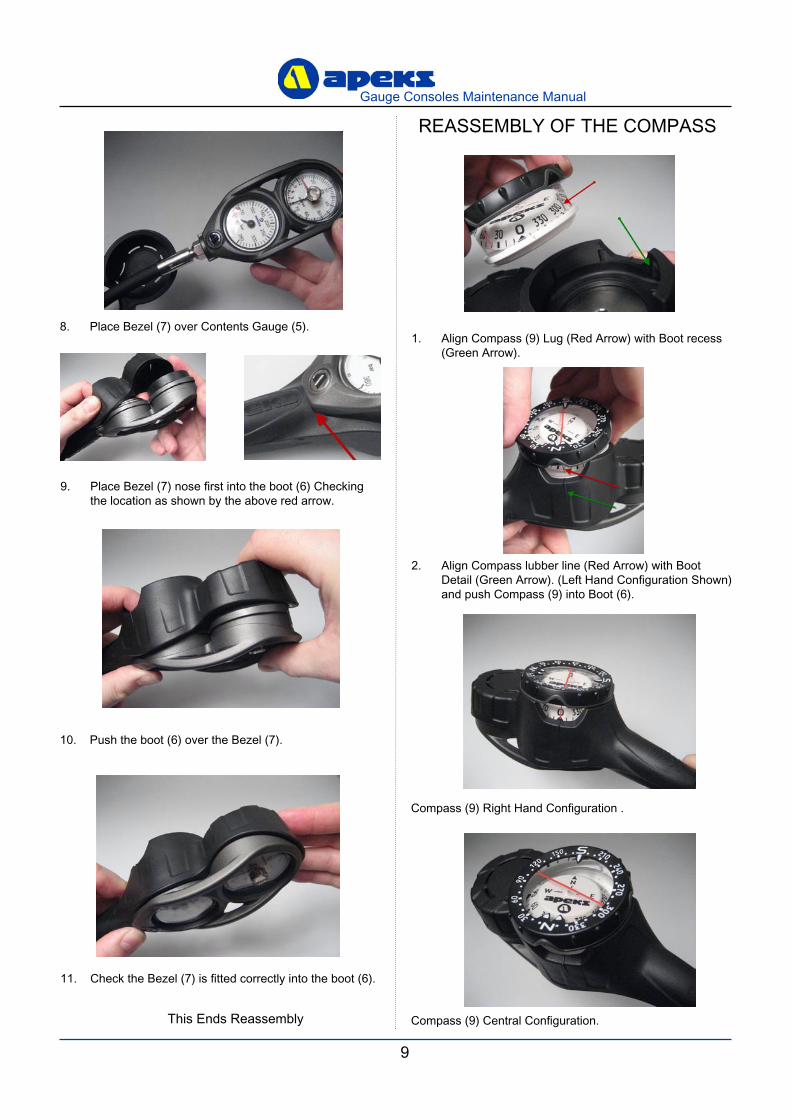
8. Place Bezel (7) over Contents Gauge (5).
9. Place Bezel (7) nose first into the boot (6) Checking the location as shown by the above red arrow.
10. Push the boot (6) over the Bezel (7).
11. Check the Bezel (7) is fitted correctly into the boot (6).
REASSEMBLY OF THE COMPASS
1. Align Compass (9) Lug (Red Arrow) with Boot recess (Green Arrow).
2. Align Compass lubber line (Red Arrow) with Boot Detail (Green Arrow). (Left Hand Configuration Shown) and push Compass (9) into Boot (6).
Compass (9) Right Hand Configuration .
Compass (9) Central Configuration.
10
Gauge Consoles Maintenance Manual
11
Gauge Consoles Maintenance Manual
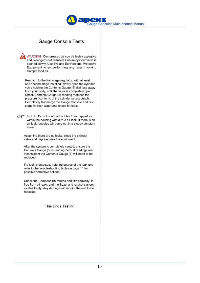
Gauge Console Tests
NOTE: Do not confuse bubbles from trapped air within the housing with a true air leak. If there is an air leak, bubbles will come out in a steady constant stream.
Reattach to the first stage regulator, with at least one second stage installed, slowly open the cylinder valve holding the Contents Gauge (5) dial face away from your body, until the valve is completely open. Check Contents Gauge (5) reading matches the pressure / contents of the cylinder or test bench. Completely Submerge the Gauge Console and first stage in fresh water and check for leaks.
Assuming there are no leaks, close the cylinder valve and depressurise the equipment.
After the system is completely vented, ensure the Contents Gauge (5) is reading Zero. If readings are inconsistant the Contents Gauge (5) will need to be replaced.
If a leak is detected, note the source of the leak and refer to the troubleshooting table on page 11 for possible corrective actions.
This Ends Testing
WARNING: Compressed air can be highly explosive and is dangerous if misused. Ensure cylinder valve is opened slowly. Use Eye and Ear Personal Protective Equipment when performing any tests involving Compressed air.
Check the Compass (9) rotates and tilts correctly, is free from oil leaks and the Bezel and ratchet system rotates freely. Any damage will require the unit to be replaced.
10
Gauge Consoles Maintenance Manual
11
Gauge Consoles Maintenance Manual
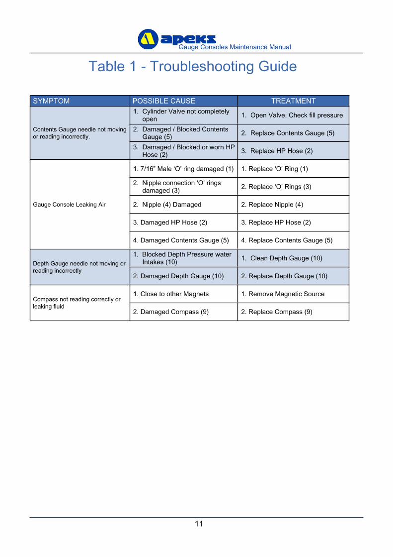
Table 1 - Troubleshooting Guide
SYMPTOM POSSIBLE CAUSE TREATMENT
Contents Gauge needle not moving or reading incorrectly.
1. Cylinder Valve not completely open 1. Open Valve, Check fill pressure
2. Damaged / Blocked Contents Gauge (5) 2. Replace Contents Gauge (5)
3. Damaged / Blocked or worn HP Hose (2) 3. Replace HP Hose (2)
Gauge Console Leaking Air
1. 7/16” Male ‘O’ ring damaged (1) 1. Replace ‘O’ Ring (1)
2. Nipple connection ‘O’ rings damaged (3) 2. Replace ‘O’ Rings (3)
2. Nipple (4) Damaged 2. Replace Nipple (4)
3. Damaged HP Hose (2) 3. Replace HP Hose (2)
4. Damaged Contents Gauge (5) 4. Replace Contents Gauge (5)
Depth Gauge needle not moving or reading incorrectly
1. Blocked Depth Pressure water Intakes (10) 1. Clean Depth Gauge (10)
2. Damaged Depth Gauge (10) 2. Replace Depth Gauge (10)
Compass not reading correctly or leaking fluid
1. Close to other Magnets 1. Remove Magnetic Source
2. Damaged Compass (9) 2. Replace Compass (9)
12
Gauge Consoles Maintenance Manual
13
Gauge Consoles Maintenance Manual
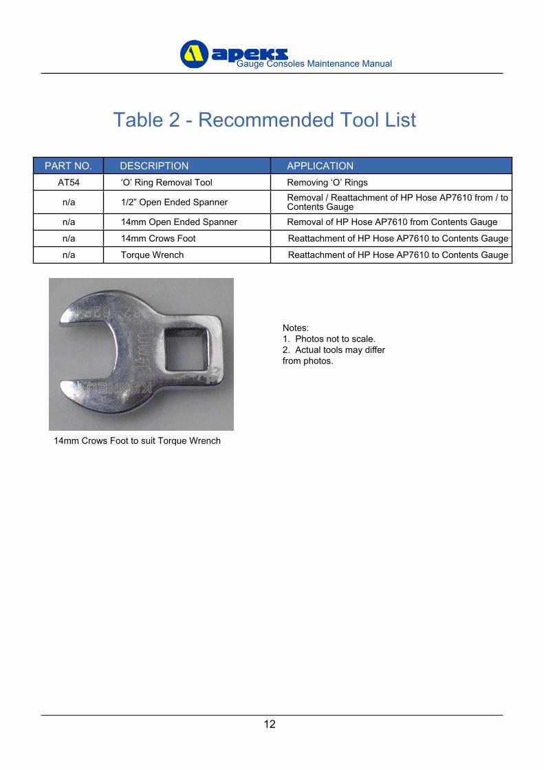
Table 2 - Recommended Tool List
PART NO. DESCRIPTION APPLICATIONAT54 ‘O’ Ring Removal Tool Removing ‘O’ Rings
n/a 1/2” Open Ended Spanner Removal / Reattachment of HP Hose AP7610 from / to Contents Gauge
n/a 14mm Open Ended Spanner Removal of HP Hose AP7610 from Contents Gauge
n/a 14mm Crows Foot Reattachment of HP Hose AP7610 to Contents Gauge
n/a Torque Wrench Reattachment of HP Hose AP7610 to Contents Gauge
Notes: 1. Photos not to scale.2. Actual tools may differ from photos.
14mm Crows Foot to suit Torque Wrench
12
Gauge Consoles Maintenance Manual
13
Gauge Consoles Maintenance Manual
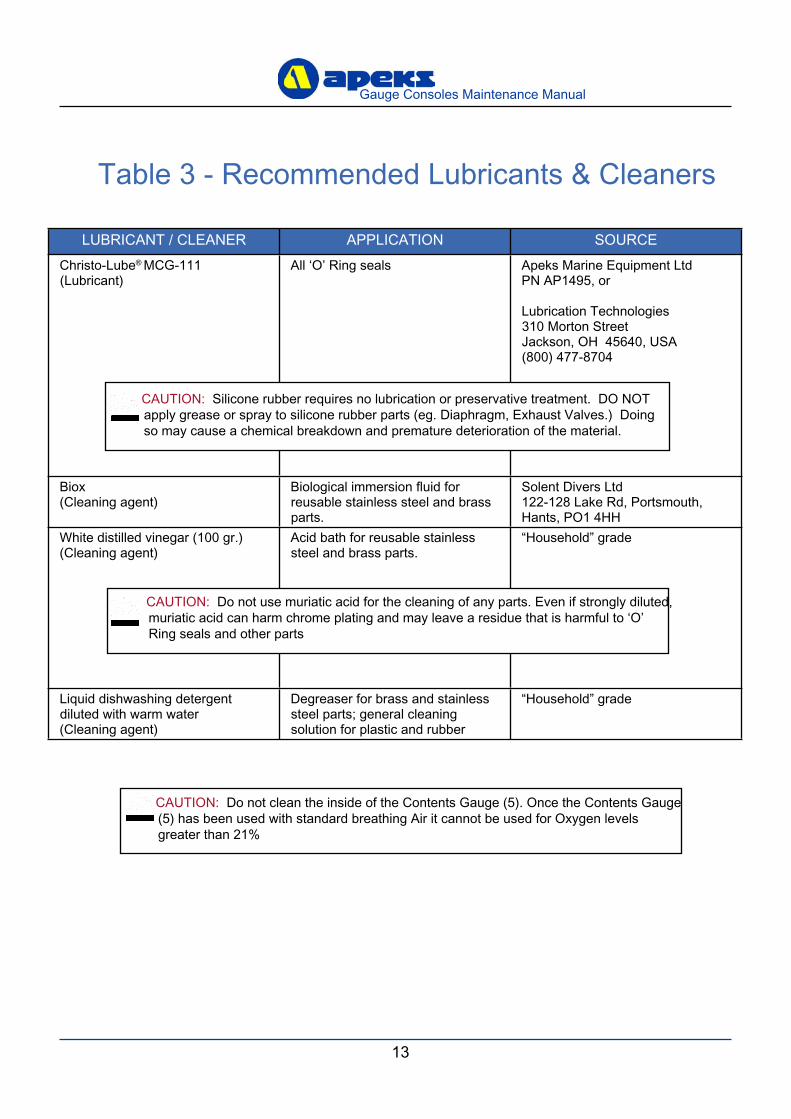
Table 3 - Recommended Lubricants & Cleaners
LUBRICANT / CLEANER APPLICATION SOURCEChristo-Lube® MCG-111(Lubricant)
All ‘O’ Ring seals Apeks Marine Equipment LtdPN AP1495, or
Lubrication Technologies310 Morton StreetJackson, OH 45640, USA(800) 477-8704
Biox(Cleaning agent)
Biological immersion fluid for reusable stainless steel and brass parts.
Solent Divers Ltd122-128 Lake Rd, Portsmouth,Hants, PO1 4HH
White distilled vinegar (100 gr.)(Cleaning agent)
Acid bath for reusable stainless steel and brass parts.
“Household” grade
Liquid dishwashing detergent diluted with warm water(Cleaning agent)
Degreaser for brass and stainless steel parts; general cleaning solution for plastic and rubber
“Household” grade
CAUTION: Silicone rubber requires no lubrication or preservative treatment. DO NOT apply grease or spray to silicone rubber parts (eg. Diaphragm, Exhaust Valves.) Doing so may cause a chemical breakdown and premature deterioration of the material.
CAUTION: Do not use muriatic acid for the cleaning of any parts. Even if strongly diluted, muriatic acid can harm chrome plating and may leave a residue that is harmful to ‘O’ Ring seals and other parts
CAUTION: Do not clean the inside of the Contents Gauge (5). Once the Contents Gauge (5) has been used with standard breathing Air it cannot be used for Oxygen levels greater than 21%
14
Gauge Consoles Maintenance Manual
15
Gauge Consoles Maintenance Manual
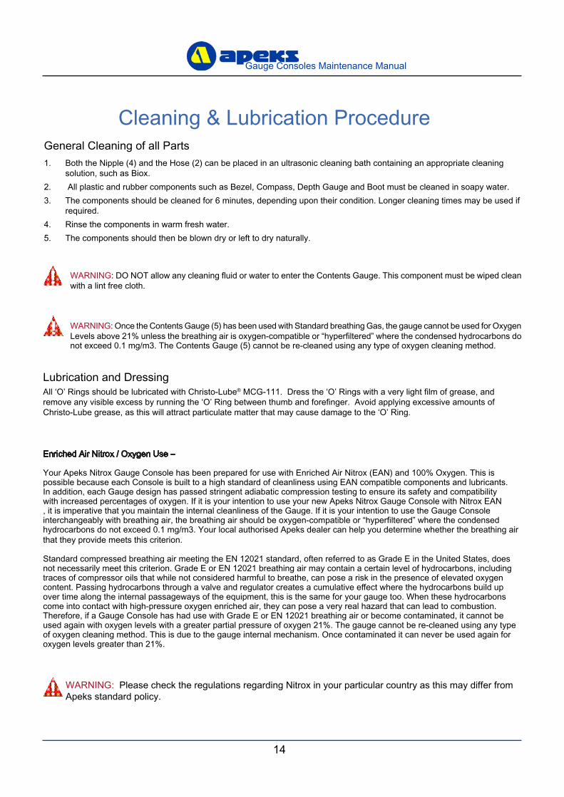
Cleaning & Lubrication Procedure
WARNING: Please check the regulations regarding Nitrox in your particular country as this may differ from Apeks standard policy.
Lubrication and DressingAll ‘O’ Rings should be lubricated with Christo-Lube® MCG-111. Dress the ‘O’ Rings with a very light film of grease, and remove any visible excess by running the ‘O’ Ring between thumb and forefinger. Avoid applying excessive amounts of Christo-Lube grease, as this will attract particulate matter that may cause damage to the ‘O’ Ring.
Enriched Air Nitrox / Oxygen Use –
Your Apeks Nitrox Gauge Console has been prepared for use with Enriched Air Nitrox (EAN) and 100% Oxygen. This is possible because each Console is built to a high standard of cleanliness using EAN compatible components and lubricants. In addition, each Gauge design has passed stringent adiabatic compression testing to ensure its safety and compatibility with increased percentages of oxygen. If it is your intention to use your new Apeks Nitrox Gauge Console with Nitrox EAN , it is imperative that you maintain the internal cleanliness of the Gauge. If it is your intention to use the Gauge Console interchangeably with breathing air, the breathing air should be oxygen-compatible or “hyperfiltered” where the condensed hydrocarbons do not exceed 0.1 mg/m3. Your local authorised Apeks dealer can help you determine whether the breathing air that they provide meets this criterion.
Standard compressed breathing air meeting the EN 12021 standard, often referred to as Grade E in the United States, does not necessarily meet this criterion. Grade E or EN 12021 breathing air may contain a certain level of hydrocarbons, including traces of compressor oils that while not considered harmful to breathe, can pose a risk in the presence of elevated oxygen content. Passing hydrocarbons through a valve and regulator creates a cumulative effect where the hydrocarbons build up over time along the internal passageways of the equipment, this is the same for your gauge too. When these hydrocarbons come into contact with high-pressure oxygen enriched air, they can pose a very real hazard that can lead to combustion. Therefore, if a Gauge Console has had use with Grade E or EN 12021 breathing air or become contaminated, it cannot be used again with oxygen levels with a greater partial pressure of oxygen 21%. The gauge cannot be re-cleaned using any type of oxygen cleaning method. This is due to the gauge internal mechanism. Once contaminated it can never be used again for oxygen levels greater than 21%.
WARNING: DO NOT allow any cleaning fluid or water to enter the Contents Gauge. This component must be wiped clean with a lint free cloth.
General Cleaning of all Parts1. Both the Nipple (4) and the Hose (2) can be placed in an ultrasonic cleaning bath containing an appropriate cleaning
solution, such as Biox.2. All plastic and rubber components such as Bezel, Compass, Depth Gauge and Boot must be cleaned in soapy water.3. The components should be cleaned for 6 minutes, depending upon their condition. Longer cleaning times may be used if
required.4. Rinse the components in warm fresh water.5. The components should then be blown dry or left to dry naturally.
WARNING: Once the Contents Gauge (5) has been used with Standard breathing Gas, the gauge cannot be used for Oxygen Levels above 21% unless the breathing air is oxygen-compatible or “hyperfiltered” where the condensed hydrocarbons do not exceed 0.1 mg/m3. The Contents Gauge (5) cannot be re-cleaned using any type of oxygen cleaning method.
14
Gauge Consoles Maintenance Manual
15
Gauge Consoles Maintenance Manual
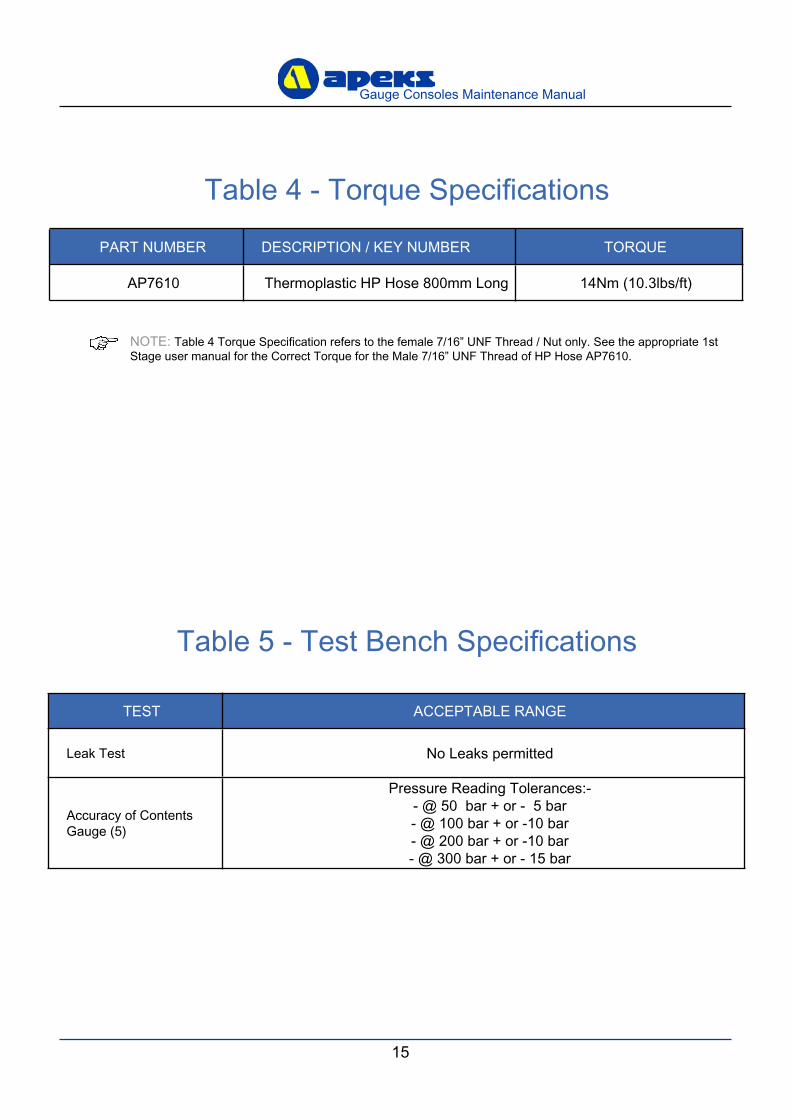
Table 5 - Test Bench Specifications
TEST ACCEPTABLE RANGE
Leak Test No Leaks permitted
Accuracy of Contents Gauge (5)
Pressure Reading Tolerances:-- @ 50 bar + or - 5 bar- @ 100 bar + or -10 bar- @ 200 bar + or -10 bar- @ 300 bar + or - 15 bar
Table 4 - Torque Specifications
PART NUMBER DESCRIPTION / KEY NUMBER TORQUE
AP7610 Thermoplastic HP Hose 800mm Long 14Nm (10.3lbs/ft)
NOTE: Table 4 Torque Specification refers to the female 7/16” UNF Thread / Nut only. See the appropriate 1st Stage user manual for the Correct Torque for the Male 7/16” UNF Thread of HP Hose AP7610.
16
Gauge Consoles Maintenance Manual
17
Gauge Consoles Maintenance Manual
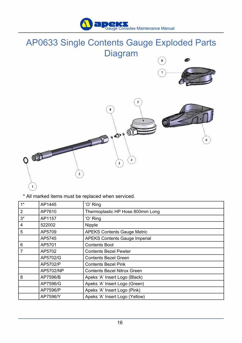
1* AP1445 ‘O’ Ring2 AP7610 Thermoplastic HP Hose 800mm Long3* AP1157 ‘O’ Ring4 522002 Nipple5 AP5709 APEKS Contents Gauge Metric
AP5745 APEKS Contents Gauge Imperial6 AP5701 Contents Boot7 AP5702 Contents Bezel Pewter
AP5702/G Contents Bezel GreenAP5702/P Contents Bezel PinkAP5702/NP Contents Bezel Nitrox Green
8 AP7596/B Apeks ‘A’ Insert Logo (Black)AP7596/G Apeks ‘A’ Insert Logo (Green)AP7596/P Apeks ‘A’ Insert Logo (Pink)AP7596/Y Apeks ‘A’ Insert Logo (Yellow)
* All marked items must be replaced when serviced.
AP0633 Single Contents Gauge Exploded Parts Diagram
16
Gauge Consoles Maintenance Manual
17
Gauge Consoles Maintenance Manual
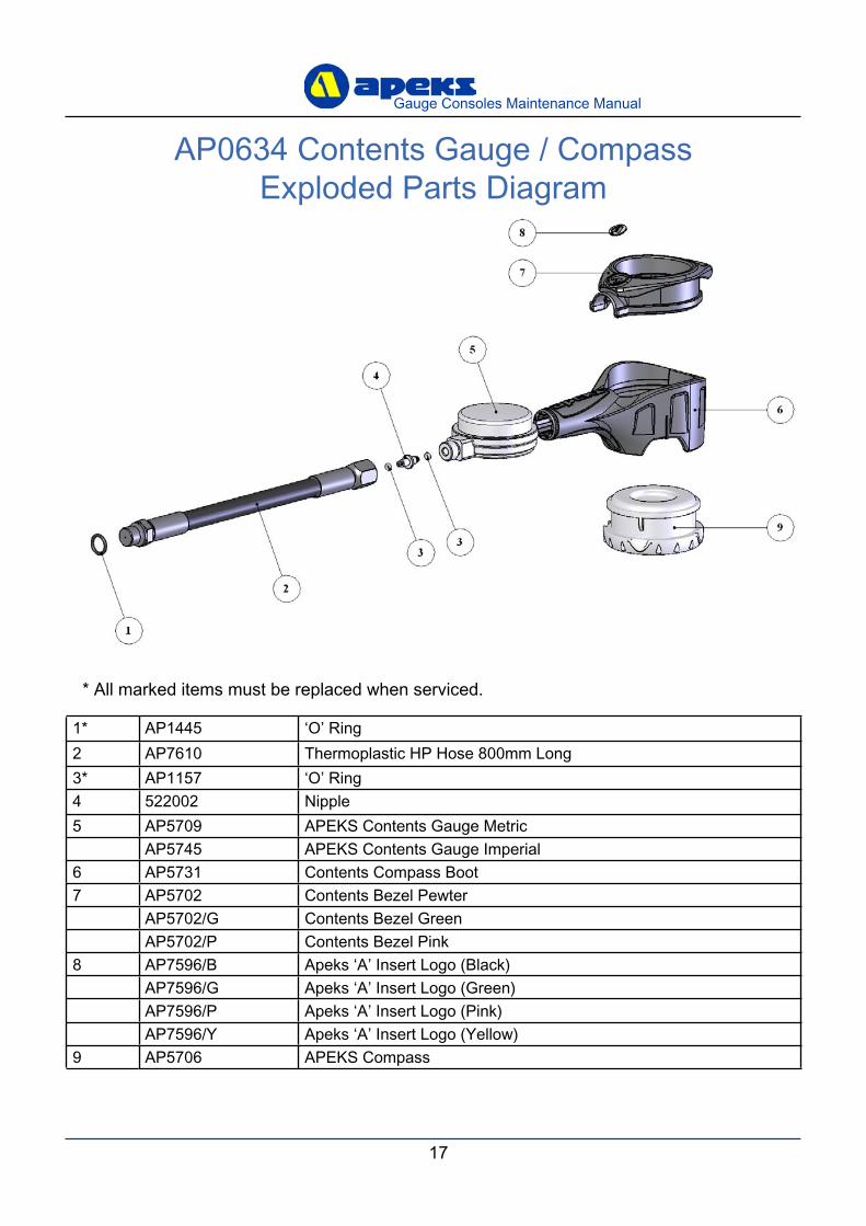
1* AP1445 ‘O’ Ring2 AP7610 Thermoplastic HP Hose 800mm Long3* AP1157 ‘O’ Ring4 522002 Nipple5 AP5709 APEKS Contents Gauge Metric
AP5745 APEKS Contents Gauge Imperial6 AP5731 Contents Compass Boot7 AP5702 Contents Bezel Pewter
AP5702/G Contents Bezel GreenAP5702/P Contents Bezel Pink
8 AP7596/B Apeks ‘A’ Insert Logo (Black)AP7596/G Apeks ‘A’ Insert Logo (Green)AP7596/P Apeks ‘A’ Insert Logo (Pink)AP7596/Y Apeks ‘A’ Insert Logo (Yellow)
9 AP5706 APEKS Compass
* All marked items must be replaced when serviced.
AP0634 Contents Gauge / Compass Exploded Parts Diagram
18
Gauge Consoles Maintenance Manual
19
Gauge Consoles Maintenance Manual
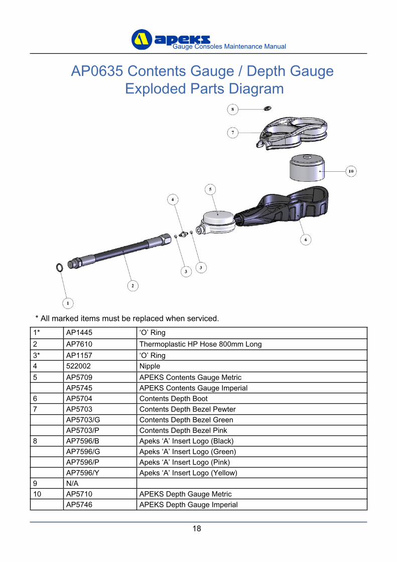
1* AP1445 ‘O’ Ring2 AP7610 Thermoplastic HP Hose 800mm Long3* AP1157 ‘O’ Ring4 522002 Nipple5 AP5709 APEKS Contents Gauge Metric
AP5745 APEKS Contents Gauge Imperial6 AP5704 Contents Depth Boot7 AP5703 Contents Depth Bezel Pewter
AP5703/G Contents Depth Bezel GreenAP5703/P Contents Depth Bezel Pink
8 AP7596/B Apeks ‘A’ Insert Logo (Black)AP7596/G Apeks ‘A’ Insert Logo (Green)AP7596/P Apeks ‘A’ Insert Logo (Pink)AP7596/Y Apeks ‘A’ Insert Logo (Yellow)
9 N/A10 AP5710 APEKS Depth Gauge Metric
AP5746 APEKS Depth Gauge Imperial
* All marked items must be replaced when serviced.
AP0635 Contents Gauge / Depth Gauge Exploded Parts Diagram
18
Gauge Consoles Maintenance Manual
19
Gauge Consoles Maintenance Manual
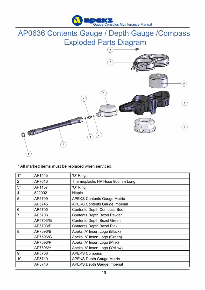
1* AP1445 ‘O’ Ring2 AP7610 Thermoplastic HP Hose 800mm Long3* AP1157 ‘O’ Ring4 522002 Nipple5 AP5709 APEKS Contents Gauge Metric
AP5745 APEKS Contents Gauge Imperial6 AP5705 Contents Depth Compass Boot7 AP5703 Contents Depth Bezel Pewter
AP5703/G Contents Depth Bezel GreenAP5703/P Contents Depth Bezel Pink
8 AP7596/B Apeks ‘A’ Insert Logo (Black)AP7596/G Apeks ‘A’ Insert Logo (Green)AP7596/P Apeks ‘A’ Insert Logo (Pink)AP7596/Y Apeks ‘A’ Insert Logo (Yellow)
9 AP5706 APEKS Compass10 AP5710 APEKS Depth Gauge Metric
AP5746 APEKS Depth Gauge Imperial
* All marked items must be replaced when serviced.
AP0636 Contents Gauge / Depth Gauge /Compass Exploded Parts Diagram

Notes
Gauge Consoles
COMPETENT TECHNICIANS
Apeks Marine Equpment LtdNeptune Way, Blackburn, Lancs, England, BB1 2BT
MAINTENANCE MANUAL
FOR
TECHNICAL SUPPORT