Embed Size (px)
Citation preview
Gateways
DMXBUS-K 2 GW612110
Programming manual

DMXBUS-K 2 - Gateways Programming manual v1.0
www.besknx.com 2
Index 1 GENERAL DESCRIPTION ........................................................................................................................................... 3
2 TECHNICAL INFORMATION ...................................................................................................................................... 3
3 PROGRAMMING ...................................................................................................................................................... 5
3.1 APPLICATION PROGRAM INFORMATION ........................................................................................................................... 5
3.2 INDIVIDUAL ADDRESS .................................................................................................................................................. 5
3.3 GENERAL PARAMETERS ................................................................................................................................................ 5
3.4 CHANNEL PARAMETERS ................................................................................................................................................ 7
3.5 GROUPS ................................................................................................................................................................... 8
3.6 SCENES ..................................................................................................................................................................... 8
3.7 SEQUENCES ............................................................................................................................................................... 9
3.8 COMMUNICATION OBJECTS ........................................................................................................................................ 12
3.8.1 Objects table ................................................................................................................................................... 12
3.8.2 Objects description .......................................................................................................................................... 12
4 INSTALLATION ....................................................................................................................................................... 15

DMXBUS-K 2 - Gateways Programming manual v1.0
www.besknx.com 3
1 General description
The device DMXBUS-K 2 with Ref. GW612110, is a bidirectional communication gateway between KNX protocol and DMX
512 protocol.
This device can work as a DMX master to regulate up to 48 DMX channels simultaneously and execute scenes or complex
sequences, and also work as a DMX slave in order to send feedbacks to the KNX home automation system, being easily
programmable through the developing software ETS.
Thanks to this gateway it is possible to develop the integration of a DMX device or system into a KNX home automation
installation, and regulate individually each DMX channel in a simply way like any other KNX dimmer or to program a
complex group of commands into several sequences.
- Bidirectional KNX-DMX gateway: Master or slave working mode.
- Controls up to 48 DMX channels simultaneously.
- Up to 8 scenes with memorization function.
- Up to 8 programmable sequences with the possibility of simultaneous execution.
- Last position memory in case of power failure.

DMXBUS-K 2 - Gateways Programming manual v1.0
www.besknx.com 4
2 Technical information
Main power supply 230Vac
Max. power consumption 2,6VA @ 230Vac
Current consumption 1 mA from KNX bus
Mounting DIN rail
Size 4 modules
Connections KNX bus connection terminal
Screw terminals for main supply and DMX bus
DMX input/output interface USITT DMX512-A
DMX Channels Up to 48 DMX channels emulation
Environment temperature
range
Operation: -10ºC/55ºC
Storage: -30ºC/60ºC
Transportation: -30ºC/60ºC
Regulation According to the directives of electromagnetic compatibility and low voltage: EN 50090-2-2 / UNE-EN 61000-6-3:2007 / UNE-EN 61000-6-1:2007 / UNE-EN 61010-1

DMXBUS-K 2 - Gateways Programming manual v1.0
www.besknx.com 5
3 Programming
3.1 Application program information
Application program: Ingenium / DMXBUS-K 2 (manufacturer / program name).
Catalogue version: v1.0
Maximum number of communication objects: 252.
Maximum number of assignments: 254.
3.2 Individual Address
The device has a programming button for the KNX individual address assignment which is located on the front of it.
A red led near the programming button lights up when it is pressed manually or if the device is set remotely to programming
mode state.
The led is automatically turned off if the ETS has assigned an individual address correctly or if the programming button is
pressed again manually.
3.3 General parameters

DMXBUS-K 2 - Gateways Programming manual v1.0
www.besknx.com 6
Name Working mode
Values Master / Slave
Description
The parameter called Working mode allows to select the gateway working mode between next two options: Master and Slave. If Master mode is selected, communication will have KNX-DMX direction. This mode allows to control the DMX channels form the KNX home automation system. Do not use any other DMX master simultaneously to avoid conflicts.
On the other hand, with Slave mode selected, communication will have DMX-KNX direction. This mode allows to receive feedbacks to the KNX system when there are changes in any DMX channels due to the use of a third party DMX master.
The working mode will be set to the selected by the parameter with any power-on initialization of the gateway.
The green led on the left of the DMX bus indicates that the gateway is currently working on Slave mode. The green led on the right of the DMX bus indicates that the gateway is currently working on Master mode
Name Number of individual channels
Values From 1 to 48
Description
The parameter called Individual DMX channels allows to select the number of DMX channel to control (from 1 to 48) simultaneously. Depending on the number of channels selected, more or less communication objects will be shown.
The DMX address of each channel can be set individually in the channel configuration menu.
Name Groups
Values Disabled / 1 … 8
Description The parameter called Groups allows to select the number of groups which you would want to control. With groups you will have the option of RGB or RGBW channels control. It is possible to have up to 8 different groups.
Name Scenes
Values Disabled / 1 … 8
Description The parameter called Scenes allows to select the number of scenes (up to 8) which you would want to configure in the gateway and which will be saved in the device memory.
Name Sequences
Values Disabled / 1 … 8
Description The parameter called Sequences allows to select the number of sequences (up to 8) which you would want to configure in the gateway and which will be saved in the device memory. A sequence is an advanced group of commands that are executed consecutively and can be defined by the programmer.
DMXBUS-K 2 - Gateways Programming manual v1.0
www.besknx.com 7
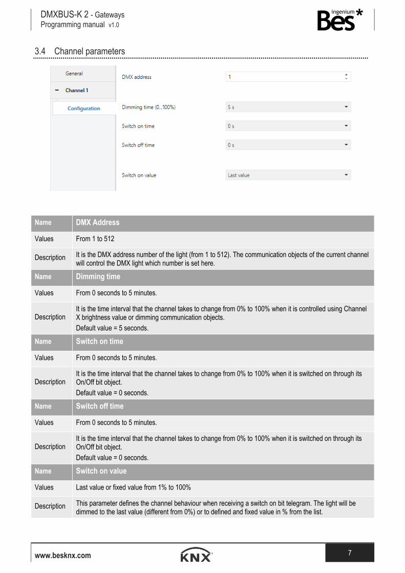
3.4 Channel parameters
Name DMX Address
Values From 1 to 512
Description It is the DMX address number of the light (from 1 to 512). The communication objects of the current channel will control the DMX light which number is set here.
Name Dimming time
Values From 0 seconds to 5 minutes.
Description It is the time interval that the channel takes to change from 0% to 100% when it is controlled using Channel X brightness value or dimming communication objects.
Default value = 5 seconds.
Name Switch on time
Values From 0 seconds to 5 minutes.
Description It is the time interval that the channel takes to change from 0% to 100% when it is switched on through its On/Off bit object.
Default value = 0 seconds.
Name Switch off time
Values From 0 seconds to 5 minutes.
Description It is the time interval that the channel takes to change from 0% to 100% when it is switched on through its On/Off bit object.
Default value = 0 seconds.
Name Switch on value
Values Last value or fixed value from 1% to 100%
Description This parameter defines the channel behaviour when receiving a switch on bit telegram. The light will be dimmed to the last value (different from 0%) or to defined and fixed value in % from the list.

DMXBUS-K 2 - Gateways Programming manual v1.0
www.besknx.com 8
3.5 Groups
A group allows to control more than one DMX channel with a 3 bytes or 4 bytes communication object, for example when
using RGB control interfaces. When groups are enabled from the general menu, each can be configured as explained next.
Name Type of group
Values 3-channel or 4-channel group
Description This parameter defines the type of group. This is the size of the communication object that allows to control the channels simultaneously.
Name Ch X. DMX address
Values From 0 to 512
Description It is the DMX address of the channel included in the group. The communication object of the group will control the DMX light whose addresses are configured here.
3.6 Scenes
The DMXBUS-K gateway allows to program up to 8 scenes. The DMX channels included in each scene can be configured
on the next menu:

DMXBUS-K 2 - Gateways Programming manual v1.0
www.besknx.com 9
In this window you can see Number of scene which can be configured from 1 to 64. This number will be the value with
which the scene will be executed with through the scenes object.
Do click on the included box to select the channels that will be member of the scene. When the scene is executed only the
channels that are included will recall their recorded value. The initial value of every channel is 100%.
When a save command is sent to the scenes object, the included channels will save their current value as the new scene
value.
3.7 Sequences
A sequence is an advanced group of commands that are executed consecutively and can be defined by the programmer. In
order to program each sequence, do click on the desired sequence of the list on the left and access to the following
parameters menu:

DMXBUS-K 2 - Gateways Programming manual v1.0
www.besknx.com 10
Name Number of sequence
Values From 1 to 64
Description This number is the value with which the sequence will be executed through the sequences object.
Name Status sending
Values Normal, disabled or only at end
Description This parameter allows to change the status sending behaviour of the device while the sequence is in execution. If disabled, the channels affected by the sequence will not send any status telegram during the execution. If only at end is set, the status telegrams will be sent when the sequence finishes or it is stopped.
Name Number of steps
Values From 1 to 24
Description Each sequence can have up to 24 steps. For each step, a different action or command can be configured. A sequence can be executed individually or simultaneously from bus commands of from other sequences.

DMXBUS-K 2 - Gateways Programming manual v1.0
www.besknx.com 11
Name Step command
Description
Brightness value: this type of step allows to change the brightness value of a DMX channel during the sequence. The brightness will increase or decrease with the dimming time programmed in parameter for this purpose.
Wait: With this type of step a delay is executed. The wait time can be defined from 0 to 4’15’’.
Loop: This command makes the sequence start from the beginning automatically. No other step of the sequence is executed after this command.
Activate scene: This command executes the scene indicated.
Start sequence and stop / Start sequence and continue: These commands allows to start the execution of another sequence simultaneously and stop or continue the current one.

DMXBUS-K 2 - Gateways Programming manual v1.0
www.besknx.com 12
3.8 Communication objects
3.8.1 Objects table
Object Name / Function Length DPT Flags
C R W T U
0 Channel 1 / On/Off 1 bit 1.001 ● ●
1 Channel 1 / On/Off status 1 bit 1.001 ● ● ●
2 Channel 1 / Dimming 4 bits 3.007 ● ●
3 Channel 1 / Brightness value 1 byte 5.001 ● ●
4 Channel 1 / Brightness value status 1 byte 5.001 ● ● ●
240 Group 1 / 3-bytes RGB control 3 bytes 232.600 ● ●
240 Group 1 / 4-bytes RGBW control 4 bytes 12.001 ● ●
248 Scenes / Scene activate/learn 1 byte 18.001 ● ●
249 Sequences / Sequence start/stop 1 byte 18.001 ● ●
250 Sequences / Full stop 1 bit 1.010 ● ●
251 Gateway working mode / Slave mode switch on/off 1 bit 1.001 ● ●
3.8.2 Objects description
Name Object 0: Channel 1 - On/Off
Function 1-bit communication object to switch on and off the channel.
Description When a “1” is received through this object the light is switched on and the brightness level goes up to the last one memorized (different from “0”) or a fixed value according to the channel parameter.
When a “0” is received through this object the light is switched off.
Name Object 1: Channel 1 - On/Off status
Function 1-bit communication object for feedback signalling of the on / off state of the channel
Description When the light is off and receives a switch on telegram or a brightness value, a “1” is sent through this object.
When the light is on and it receives a switch off telegram or a brightness value of 0% a “0” is sent through this object.

DMXBUS-K 2 - Gateways Programming manual v1.0
www.besknx.com 13
Name Object 2: Channel 1 - Dimming
Function 4-bits communication object for dimming control with pushbuttons.
Description Depending on the dimming step received, telegrams will make the brightness level go up or down according to the dimming time configured.
Break telegrams to this object will stop the brightness at the current level.
Name Object 3: Channel 1 – Brightness value
Function 1-byte communication object for controlling by a direct brightness value.
Description Brightness level will increase or decrease according to fade time configured.
Name Object 4: Channel 1 – Brightness value status
Function 1-byte communication object for feedback signalling of the current brightness level of the channel.
Description When it receives a new brightness value or an increase/decrease telegram the final brightness value is sent through this object.
Name Object 240: Group 1 – 3 byte RGB control
Function 3-byte communication object for 3 channel simultaneous control
Description This object controls a group that consist of 3 (RGB) DMX channels. It is used to be able to control three directly with a group address. 3-byte DPT 232.600 [Red Green Blue].
Name Object 240: Group 1 – 4 bytes RGBW control
Function 4-bytes communication object for 4 channel simultaneous control
Description This object controls a group that consist of 4 (RGBW) DMX channels. It is used to be able to control four directly with a group address. 4-byte DPT 12.001 [Red Green Blue White].
Name Object 248: Scenes / Scene activate/learn
Function 1-byte communication object for scene activation and learn
Description When a value from 1 to 64 is sent to this object the channel will recall its internal scene which number corresponds to the value (if included in the scene).
When a value from 128 to 191 is sent to this object the channel will save its current brightness in the scene which number corresponds to the value (if included in the scene).
The initial value the channels are 100%.
Name Object 249: Sequences / Sequence start/stop
Function 1-byte communication object for sequence start and stop
Description When a value from 1 to 64 is sent to this object, the gateway will start its internal sequence which number corresponds to the value. If the sequence is already in execution it will start from the beginning.
When a value from 128 to 191 is sent to this object, the gateway will stop its internal sequence which number corresponds to the value.

DMXBUS-K 2 - Gateways Programming manual v1.0
www.besknx.com 14
Name Object 250: Sequences / Full stop
Function 1-bit communication object to stop all sequences.
Description When a value of 0 is sent to this object, the gateway will stop all the sequences in execution.
Name Object 251: Gateway working mode / Slave mode switch on/off
Function 1-bit communication object to activate/deactivate the slave mode.
Description When a value of 1 is sent to this object, the gateway changes to Slave mode. In this mode no commands are sent to the DMX bus so it only sends feedbacks to the KNX system through the status objects if there is any DMX channel change.
When a value of 0 is sent to this object, the gateway changes to Master mode and starts to send DMX commands to the bus.

DMXBUS-K 2 - Gateways Programming manual v1.0
www.besknx.com 15
4 Installation
Feed low voltage lines (bus and inputs) in separate ducting to that of power (230Vac) and outputs to ensure
there is enough insulation and avoid interferences.
Do not connect the main voltages (230Vac) or any other external voltages to any point of the bus or inputs.

Liability limitation: The present document is subject to changes or excepted errors. The contents are continuously checked to be
according to the hardware and software but deviations cannot be completely excluded. Consequently any liability for this is not
accepted. Please inform us of any suggestion. Every correction will be incorporated in new versions of this manual.
Manual version: v1.0
Ingenium, Ingeniería y Domótica S.L.
Parque Tecnológico de Asturias, Parcela 50
33428 Llanera, Asturias, Spain
T (+34) 985 757 195
www.besknx.com
www.ingeniumsl.com