Embed Size (px)
Citation preview
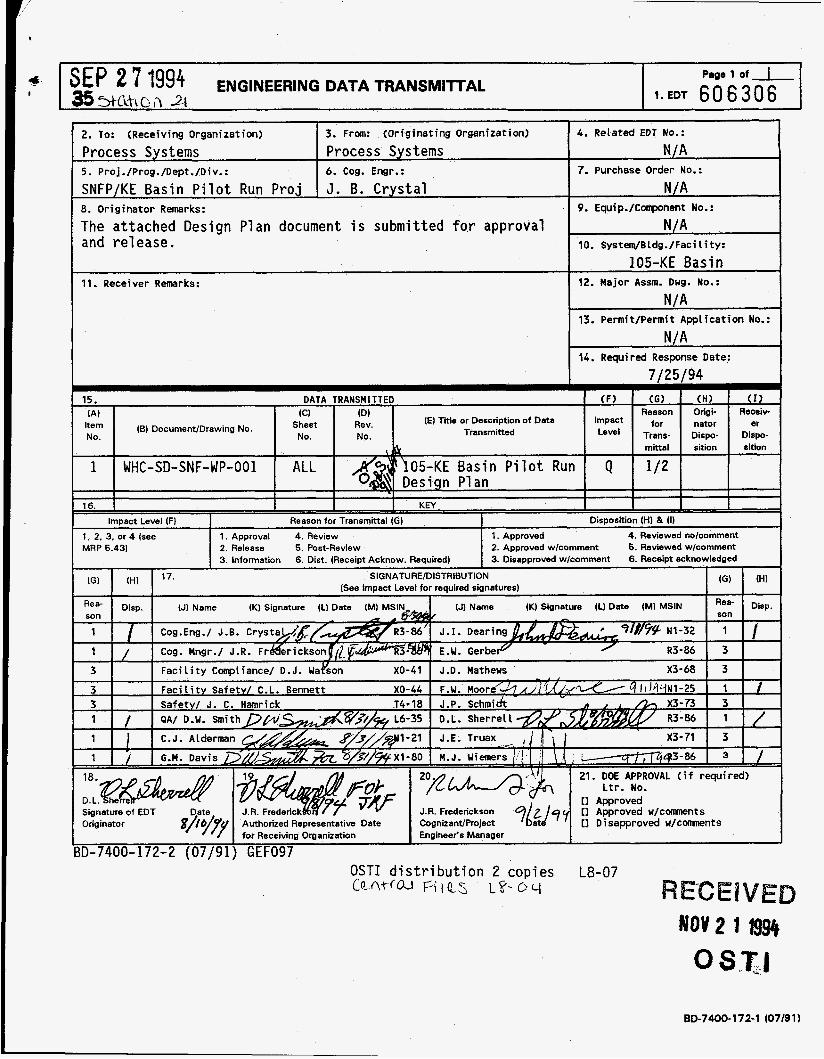
3. From: (Originating Organization) 4 . Related EDT No.: 2. To: (Receiving Organization)
Process Systems Process Systems N/A
SNFP/KE Basin P i l o t Run P r o j J. B. Crys ta l N/A 8. Originator Remarks:
The at tached Design Plan document i s submit ted f o r approval N /A and re lease. 10. System/BLdg./Facility:
105-KE Basin
N/A
\/A
7/25 r94
5 . Proj./Prog./Dept./Div.: 6. Cog. Engr.: 7. Purchase Order No.:
9. Equip./Conponent No.:
11. Receiver Remarks: 12. Major Assm. Dwg. No.:
13. Permit/Permit Application No.:
14. Required Response Date:
15. DATA TRANSMITTED (F) (6) ( H I ( r ) Reason Origi- Receir
Transmitted Level Trans- Dispo- Dispo- (E) Tile or Description of Data for nator er Impact (A) (CI (Dl
Sheet Rev. Item (BI DocumentIDrawing No. No. No. No.
\ mittal sition sition
1 WHC-SD-SNF-WP-001 ALL h05-KE Basin P i l o t Run Q 1 /2 gat Design P1 an 16. KEY
Impact Level (Fl Reason for Transmittal (GI Disposition (H) & (1)
1, 2, 3, or 4 (see 1. Approval 4. Review 1. Approved 4. Reviewed nolcomment MRP 5.43) 2. Release 5. Post-Review 2. Approved wlcomment 5. Reviewed wlcomment
3. Information 6. Dist. (Receipt Acknow. Required) 3. Disapproved wlcomment 6. Receipt acknowledged
Signature of EDT Originator
!D-7400-172-2 (07/91) GEF097 OSTI distribution 2 copies L8-07
BD-7400-172-1 (07/91)
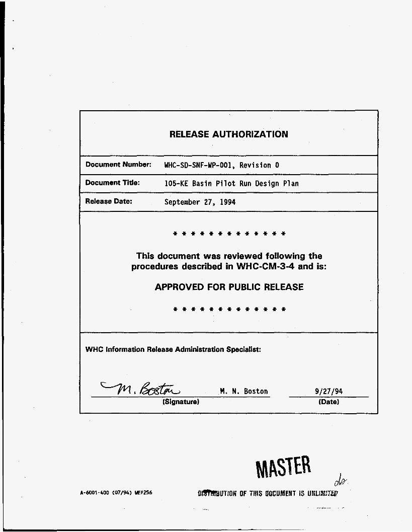
RELEASE AUTHORIZATION
Document Number: WHC-SD-SNF-WP-001, Revision 0
Document Title: 105-KE Basin P i l o t Run Design Plan
Release Date: September 27, 1994
* * * * * * * * * * * * *
This document was reviewed following the procedures described in WHC-CM-3-4 and is:
APPROVED FOR PUBLIC RELEASE
* * * * * * * * * * * * *
WHC Information Release Administration Specialist:
M. N. Boston 9/27/94 (Signature) (Date)
A-6001-400 (07/94) UEF256
DISCLAIMER
Portions of this document may be illegible in electronic image products. Images are produced from the best available original document.
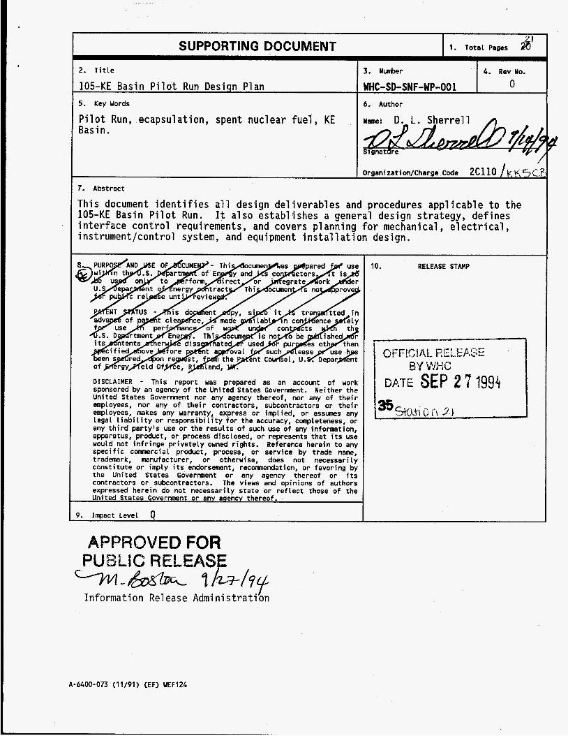
SUPPORTING DOCUMENT I 1. Total Pages fi' 2. Title
105-KE Basin Pilot Run Design Plan
Pilot Run, ecapsulation, spent nuclear fuel , KE Basin.
5. Key Words
7. Abstract
3. Nunber 4. Rev No. WHC-SD-SNF-WP-001 0
6. Author
/
This document identifies all design del iverables and procedures applicable to 105-KE Basin Pilot Run. It also establishes a general design strategy, defin interface control requirements, and covers planning for mechanical , electrica instrument/control system, and equipment installation design.
DISCLAIMER - This report was prepared as an account of work sponsored by an agency of the United States Govermnt. Neither the United States Government nor any agency thereof, nor any of their employees, nor any of their contractors, subcontractors or their employees, makes any warranty, express or implied, or assunes any legal liability or responsibility for the accuracy, completeness, or any third party's use or the results of such use of any information, apparatus, product, or process disclosed, or represents that its use would not infringe privately owned rights. Reference herein to any specific conmercial product, process, or service by trade name, trademark, manufacturer, or otherwise, does not necessarily constitute or inply its endorsement, reconmendation, or favoring by the United States Govermnt or any agency thereof or its contractors or subcontractors. The views and opinions of authors expressed herein do not necessarily state or reflect those of the United States Government or any agency thereof.
9. Inpact Level 0
APPROVED FOR PUBLIC RELEASE %-e 7 I b h y Information Re1 ease Admi ni s trati on
the S 
10. RELEASE STAMP
------I
I I DATE SEP 27 1994 1
A-6600-073 (11/91) CEF) WEF124
WHC-SD-SNF-WP-001, Rev. 0
105-KE BASIN PILOT RUN DESIGN PLAN
JULY 1994
WHC-SD-SNF-WP-001 Rev . 0
105-KE BASIN PILOT RUN DESIGN PLAN
Table o f Contents
ACRONYMS . . . . . . . . . . . . . . . . . . . . . . . . . . . . . . . . i i i
1.0 PURPOSE . . . . . . . . . . . . . . . . . . . . . . . . . . . . . . . 1
2.0SCOPE . . . . . . . . . . . . . . . . . . . . . . . . . . . . . . . . 1
3.0 ORGANIZATIONAL RESPONSIBILITIES AND INTERFACES . . . . . . . . . . . 1
4.0 DESIGN CONTROL/DOCUMENTATION . . . . . . . . . . . . . . . . . . . . 1 4.1 SAFETY CLASSES . . . . . . . . . . . . . . . . . . . . . . . 2 4.2 SPECIAL DEVELOPMENT CONTROL PROVISIONS . . . . . . . . . . . 2
2 4.2.1.1 Work Planning . . . . . . . . . . . . . . . . . 2 4.2.1.2 Control o f Documentation . . . . . . . . . . . 3 4.2.1.3 Control of Non-Facility Use Hardware . . . . . 3
4.2.2 Hardware Destined for KE Basin . . . . . . . . . . . . 4
4.3 FUNCTIONS AND REQUIREMENTS . . . . . . . . . . . . . . . . . 5 4.4 ENGINEERING DRAWINGS . . . . . . . . . . . . . . . . . . . . 5
4.4.1 Test Articles Designated Not For Facility Use . . . . . 5 4.4.2 Hardware Destined for KE Basin . . . . . . . . . . . . 5 4.4.2.1 Drawing Format and Control . . . . . . . . . . . . . 5
4.4.2.2 Development Control Drawings . . . . . . . . . 6 4.4.2.3 Three Dimensional Drawings . . . . . . . . . . 6
4.4.3 Drawing Types . . . . . . . . . . . . . . . . . . . . . 6 4.4.3.1 Process Flow Diagrams (PFD) . . . . . . . . . . 6 4.4.3.2 Interface Control . . . . . . . . . . . . . . . 6 4.4.3.3 Installation Drawings . . . . . . . . . . . . . 7 4.4.3.4 Existing KE Basin Drawings . . . . . . . . . . 7 4.4.3.5 Fabrication and Assembly Drawings . . . . . . . 7 4.4.3.6 Instrumentation and Control Drawings . . . . . 7 4.4.3.7 Electrical Power Distribution Drawings . . . . 8
4.5 ENGINEERING SPECIFICATIONS . . . . . . . . . . . . . . . . . 8 4.6 VENDOR INFORMATION . . . . . . . . . . . . . . . . . . . . . 8 4.7 ENGINEERING ANALYSES . . . . . . . . . . . . . . . . . . . . 8 4.8 EQUIPMENT NUMBERING . . . . . . . . . . . . . . . . . . . . . 8 4.9 EQUIPMENT LIST . . . . . . . . . . . . . . . . . . . . . . . 9 4.10 UTILITY LOAD SUMMARY . . . . . . . . . . . . . . . . . . . . 9 4.11 SOFTWARE DESIGN . . . . . . . . . . . . . . . . . . . . . . . 9
4.2.1 Test Articles Designated Not For Facility Use . . . . .
4.2.2.1 Work Planning . . . . . . . . . . . . . . . . . 4
i
WHC-SD-SNF-WP-001 Rev . 0
4.12 RADIOLOGICAL CONTROL DESIGN . . . . . . . . . . . . . . . . . 9 4.12.1 Shielding . . . . . . . . . . . . . . . . . . . . . . 9
4.12.1.1 General Design Requirements . . . . . . . . . 9 4.12.1.2 As Low As Reasonably Achievable (ALARA) . . . 10 4.12.1.3 Human Factors . . . . . . . . . . . . . . . . 10
4.13 QUALITY ASSURANCE PROGRAM PLAN . . . . . . . . . . . . . . . 10
5.0 DESIGN VERIFICATION . . . . . . . . . . . . . . . . . . . . . . . . . 10 5.1 FORMAL DESIGN REVIEWS . . . . . . . . . . . . . . . . . . . . 10
5.1.1 Design Review Deliverables . . . . . . . . . . . . . . 11 5.2 INDEPENDENT REVIEWS . . . . . . . . . . . . . . . . . . . . . 11 5.3 ALTERNATE CALCULATIONS . . . . . . . . . . . . . . . . . . . 12 5.4 QUALIFICATION TESTING . . . . . . . . . . . . . . . . . . . . 12 5.5 INFORMAL REVIEWS . . . . . . . . . . . . . . . . . . . . . . 12
6.0 REFERENCES . . . . . . . . . . . . . . . . . . . . . . . . . . . . . 13
APPENDIX A: DRAWING REQUIREMENTS . . . . . . . . . . . . . . . . . . . . 14
i i
WHC-SD-SNF-WP-001 Rev. 0
ACRONYMS
ECN
EDT
EP
EPG
F &R
I &C
ICD
I SA MRP
P&ID
SD
SEL
Engineering Change Not ice
Eng i neeri ng Data Transmit t a1
Engineering Practice (requirements from WHC-CM-6-1)
Engineering Practice Guideline (from WHC-IP-1026)
Functions and Requirements
Instrumentation and Control
Interface Control Drawings
Instrument Society of America
WHC Management Requirements and Procedures
Piping and Instrumentation Diagrams
Supporting Document
Safety Equipment List
i i i
WHC-SD-SNF-WP-001 Rev. 0
105-KE BASIN PILOT RUN DESIGN PLAN
1.0 PURPOSE
The purpose of this document is to provide guidance for implementing the design phase o f the KE Basin Pilot Run project.
2.0 SCOPE
This document augments and supports the 105-KE Basin P i l o t Run Pro jec t Management Plan (WHC-SD-SNF-PMP-001) by identifying all design del iverables and procedures applicable to the Pilot Run. general design strategy, defines interface control requirements, and covers planning for mechanical, electrical, instrument/control system, and equipment installation design. particular emphasis on WHC-CM-6-1 , EP-2.4 requirements for control of the process equipment designs (see section 4.2, below). Software design, if required, will be performed and controlled to the requirements of WHC-CM-3-10, as described in section 4.11, below.
This document establishes a
It also spells out applicable requirements, with
3.0 ORGANIZATIONAL RESPONSIBILITIES AND INTERFACES
The 105-KE Basin P i l o t Run Pro jec t Management Piran, (WHC-SD-SNF-PMP-001) establishes fundamental organizational charters and interfaces for the design.
4.0 DESIGN CONTROL/DOCUMENTATION
Individual documents and activities that are required to complete, document, and implement the designs are defined in this section, along with the means by which they will be control1,ed.
The overall project shall be developed and controlled as a minor
While design and fabrication of most project along the general guide1 ines provided by WHC-IP-1026 EPG-2.0 (Engineering System Design Control). Pilot Run test articles and at least some Pilot Run support equipment is expected to fa1 1 under the special development control provisions afforded by
1
WHC-SD-SNF-WP-001 Rev. 0
WHC-CM-6-1 EP-2.4 performed to draw WHC-CM-6-1 EP-1.3 (SD) are required 2.2.
(see section 4.2 below), all site installations shall be ngs which have been prepared, released, and controlled per and EP-2.2. Where formal ly re1 eased supporting documents they shall be prepared and controlled per EP-1.12 and EP-
4.1 SAFETY CLASSES
Equipment safety classes shall be determined and documented in accordance with the requirements of WHC-CM-1-3, MRP 5.46.
4.2 SPECIAL DEVELOPMENT CONTROL PROVISIONS
At the discretion of the cognizant engineer, fabrication and assembly drawings (but not KE Basin facility installation drawings) for first-of-a-kind equipment and/or equipment modifications may be controlled via the special provisions afforded by EP-2.4 (Development Control).
Figure 11 of WHC-IP-1026 EPG-1.0 depicts two markedly different levels of control which may be appropriate for design of test articles and other equipment under EP-2.4. application of these different levels of control (or formality) to design, fabrication/procurement, and assembly of Pilot Run test articles and support equipment.
The following subsections spell out conditions for
4.2.1 Test Articles Designated Not For Facility Use
assembly in a cold facility, prior to designing and fabricating the actual pilot run test article or Pilot Run support equipment item, the prototype may be fabricated and cold tested under the non-facility use provisions of EP 2.4 .
Where it would be beneficial to feature test a prototype component or
4.2.1.1 Work Planning. of non-facility use equipment to be controlled by an informal work plan. work plan is required to identify the following:
Section 2.2-2 of EP 2.4 allows design and fabrication The
a.
b.
C.
Description of the work to be performed, supported by applicable sketches, drawings, and specifications;
Any restrictions and/or special conditions;
Work order number and/or charge code number (not required for initial
2
WHC-SD-SNF-WP-001 Rev. 0
design pl an) ;
d.
e.
f.
h.
Inspection/fabrication criteria (Hold points shall be established when critical features require verification.);
Material requirements;
Special testing requirements or practices;
Shipping and hand1 ing instructions;
Del i very date.
4.2.1.2 Control of Documentation. Section 2 . 3 . 2 - 1 of EP 2 . 4 allows the cognizant engineer to determine the degree of design documentation and change control appropriate for non-faci 1 i ty use hardware. Section 2 . 3 . 2 - 2 assumes that all drawings, sketches, or specifications are attachments to the informal work plan and requires that all changes to them be documented in accordance with a control method established within the informal work plan. requires that all changes be authorized by the cognizant engineer.
It further
4.2.1.3 Control of Non-Facility Use Hardware. requires that a1 1 ' I . . . hardware produced from informal workplan documentation ..." be clearly identified "not for use" and either properly disposed, or retained in segregated storage.
Section 2 .3 .2 -3 of EP 2 . 4
4.2.1.3.1 Disposition of Off-The-Shelf Hardware. The EP does not directly address disposition of off-the-shelf components (pumps, flow meters, etc.), which have been removed from non-facility use test assemblies. For the work covered by this design plan, off-the-shelf items purchased prior to release of a formal development control work plan may be incorporated into final pilot run assemblies which have been designed and fabricated under the formal work plan control provisions of section 4 . 2 . 2 below, provided that: (1) the purchased items have not been modified; and ( 2 ) the procurement actions for the items in question have been controlled and documented in accordance with requirements which are appropriate to the assigned Safety Class(s) of the associated pilot run assemblies (see sections 4 . 1 above, and 4 . 1 3 below).
4.2.1.4 Non-Facil ity Use Design Process Guidelines Guide1 ines for application of the non-facility use provisions of EP-2.4 are provided in section 3.0 of WHC-IP-1026 EPG-2.4. A schematic diagram of the engineering process for control of non-facility use hardware is provided in Figure 3 of EPG-2.4.
3
WHC-SD-SNF-WP-001 Rev. 0
4.2.2 Hardware Destined for KE Basin
Where the intent is to fabricate test articles, Pilot Run support equipment, etc., which will eventually be operated at KE Basin, it will be necessary to maintain rigorous control throughout all stages of the design. Note, however, that fabrication and assembly of initial feature test articles and prototypes for cold testing need not be rigorously controlled, unless it is desirable to retain an option for eventual KE Basin testing o f the hardware in question (see section 4.2.1 above).
The following subsections spell out the minimum design control requirements for fabrication/procurement and assembly of a1 1 hardware which will either be tested by the KE Basin Pilot Run or which will be installed at KE Basin to support the Pilot Run. Note that in the particular case of the Pilot Run, the minimum design control requirements are the "facil ity-use potential" sections of EP 2.4 (DEVELOPMENT CONTROL). Where more rigorous controls are considered desirable by the cognizant equipment development engineers, they may apply them at their discretion.
4.2.2.1 Work Planning. process for hardware with facil ity-use potential" be documented by an engineering work plan which has been approved and released in accordance with EP-1.12.
Section 2.2 o f EP 2.4 requires that "the development
The work plan is required to identify the following:
"A description of the work to be performed, supported by applicable ... drawings and specifications." For the purposes of this document, the appendices should include an itemized list of the H-1 drawing numbers, sheet numbers, and titles for all drawings to be used under the development control provisions of EP-2.4. The drawing list will effectively attach those drawings to this document (assumed by section 2.3.1-1 of EP-2.4).
"Any restrictions and/or special conditions."
"Work order number and/or charge code number." [Supply with the fabrication requests. 3 "Inspect i on/fabri cat i on criteria. The cognizant engineer shall establish hold points when critical features require verification."
"Material requirements."
"Spec i a1 test i ng requ i remen t s or prac t i ce s . It "Safety class designation in accordance with WHC-CM-4-46 'I (Use WHC-
4
WHC-SD-SNF-WP-001 Rev. 0
CM-1-3, MRP 5.46)
h) "Approval designator assignment in accordance with WHC-CM-3-5, Section 12.7. 'I
"Shipping and handling instructions."
"Delivery date." [Provide an overall schedule for design, fabrication, cold testing, and KE Basins installation.]
4.3 FUNCTIONS AND REQUIREMENTS
In addition to the overall project functions and requirements provided in WHC-SD-SNF-FRD-002, detailed functional descriptions and requirements (incl udi ng performance requirements) shall be provided for a1 1 systems and major assemblies to provide and document the design bases. These may be issued as separate SDs, or included in the engineering work plan documents (see section 4.2 above). The functions and requirements shall be the basis against which all designs are ultimately reviewed and evaluated.
4.4 ENGINEERING DRAWINGS
The following sections address preparation and control o f drawings and/or sketches used for fabrication, assembly, or installation of hardware.
4.4.1 Test Articles Designated Not For Facility Use
Shop fabrication of feature test articles and other prototype equipment which has been designated "not for facility use" per section 4.2.1 above, may be accomplished via informal sketches, formal drawings, or any combination of these deemed appropriate by the responsible cognizant engineer.
4.4.2 Hardware Destined for KE Basin
4.4.2.1 Drawing Format and Control All fabrication, assembly, and installation of facility-use hardware shall be performed using two dimensional , AutoCad format, H-1 drawings, drawn to the requirements of EP-1.3 (PREPARATION OF ENGINEERING DRAWINGS) and Appendix A of this document. All H-1 drawing numbers shall be assigned from a block of drawing numbers controlled by the cognizant design organization's designated lead designer.
5
WHC-SD-SNF-WP-001 Rev. 0
4.4.2.2 Development Control Drawings. Per section 4.2 above, fabrication and assembly drawings (but not installation drawings) may be controlled via the special provisions afforded by EP-2.4 (DEVELOPMENT CONTROL). their acceptability per EP-2.4, engineering sketches shall not be used to control shop fabrication and assembly of any hardware with the potential for use at the KE Basin. This work will instead be performed using H-1 format drawings, prepared to the requirements of EP-1.3 and Appendix A of this document.
However, despite
All unreleased fabrication and assembly drawings that are used (per section 2.3.1 of EP-2.4) to fabricate and/or assemble equipment shall be marked "development control . ' I All changes, additions, or deletions shall be approved by the cognizant engineer's dated signature next to each change. Affected drawings shall not be revised by an Engineering Change Notice (ECN) while under development control. At the end of the fabrication and/or assembly process, all changes shall be formally incorporated onto the drawings, and the drawings shall be released per EP-1.7. This process shall include as-building, in accordance with section 2.4 (Prototype Conversion) of EP-2.4. Any discrepancies discovered during the as-building process shall be documented, evaluated, and dispositioned per section QI 15.1, "Nonconforming Item Reporting," of WHC's Q u a l i t y Assurance Manual, (WHC-CM-4-2).
4.4.2.3 Three Dimensional Drawings. Unreleased three dimensional AutoCad drawings (i.e., sketches), may be used for conceptual design support purposes, and/or for figures in SDs, along with unreleased two-dimensional sketches. However, three dimensional drawings shall not be used for fabrication and/or assembly, nor shall they be released.
4.4.3 Drawing Types
will be issued to support fabrication, assembly, and installation of facility- use hardware.
The following subsections list and describe the types of drawings which
4.4.3.1 Process Flow Diagrams (PFD). Process Flow Diagrams shall be issued as H-1 drawings to provide schematic process overview information which will be used to describe and control the functional design of all major assemblies and systems. The PFDs shall: outline the major process activities and material flow streams and track critical process information (e.g., material flow rates, etc.) All PFDs shall be released prior to installation of all systems, assemblies, and other equipment which they describe.
4.4.3.2 Interface Control. Interface Control Drawings as such, are not required for fabrication, assembly, nor installation of any equipment
6
WHC-SD-SNF-WP-001 Rev. 0
associated with the Pilot Run project. In lieu of interface control drawings, all critical physical and functional interfaces (power connections, clear openings, install ation/operating envelopes, etc.) shall be documented directly on other drawings, as appropriate. All physical interfaces shall be identified by enumerated interface control symbols (described in WHC-CM-6-3) on appropriate drawing views.
4.4.3.3 Installation Drawings. The installation drawing category covers all design information required for installation of major equipment assemblies and systems (including electrical and instrumentation). These typically include a combination of arrangements, elevations, layouts, and details. drawings may include fabrication and assembly drawings for conduit supports, equipment foundations, and other detailed views required to install the major assemblies and systems.
4.4.3.4 Existing KE Basin Drawings. required for installation of the Pilot Run Project, a number of ECNs may be required against existing KE Basin drawings to implement and document installation of the equipment into the Basin.
The detail
In addition to those new drawings
4.4.3.5 Fabrication and Assembly Drawings. category covers all of the traditional layout, elevation, and detail drawings required to procure, fabricate, and/or assemble parts into major equipment assemblies. With a few exceptions (i .e., vendor drawings, or shop drawings for support equipment such as skid mounted hydraulic power systems, etc.) these drawings will be directed to the Westinghouse Hanford (WHC) shops for fabrication and/or assembly of the process equipment and/or equipment modifications. Therefore, most fabrication and assembly drawings will fall under the speci a1 devel opment control provisions of EP-2.4, per section 4.4.2.2 above.
The fabrication and assembly
4.4.3.6 Instrumentation and Control Drawings. With the exception of electrical power drawings, the instrumentation and control category includes all drawings required to procure, fabricate/assemble and install the sensors, effectors, control equipment, instrument runs (including pneumatic sensor or control lines) , and electrical signal wiring. While this category does include all required electrical instrument wiring and conduit runs, it does not include electrical power distribution drawings (see section 4.4.3.7 below). diagrams; electrical connection diagrams; wire run lists; panel assemblies; conduit runs; and pneumatic or hydraulic tube runs. Much of the required functional interface information could also be shown on these drawings. installation details which do not fall into the above mentioned drawing types may be placed on Installation Drawings, if desired.
Typical drawing types include: circuit schedules; elementary wiring
Any
7
WHC-SD-SNF-WP-001 Rev. 0
4.4.3.7 Electrical Power Distribution Drawings. This category includes all drawings required to procure, fabricate/assemble and install motor control centers, breaker panels, and/or electrical power distribution wiring/condui t runs. Typical drawing types include: circuit and breaker schedules; elementary wiring diagrams; electrical connection diagrams; wire run lists; panel assemblies; and conduit. Much of the required functional interface information could also be shown on these drawings. Any installation details which do not fall into the above mentioned drawing types may be placed on Installation Drawings, if desired.
4.5 ENGINEERING SPECIFICATIONS
With the exception of procurements which uti1 ize WHC produced detailed design drawings, engineering specifications shall be required for those procurement contracts that are not limited to off-the-shelf equipment (i.e., catalog items). In addition, any outside contracts for testing or assembly shall be controlled by an engineering specification. Such specifications shall be written to the requirements of EP-1.2 and EP-5.8.
4.6 VENDOR INFORMATION
Vendor information shall be documented per EP-3.3.
4.7 ENGINEERING ANALYSES
Various engineering analyses may be required to define design requirements and verify adequacy of designs. These analyses will generally fall into one of the following analysis categories: Structural , Shielding, Thermal , Seismic, Failure Modes and Effects, and various process specific categories (fluid flow, etc.). In most cases, these analyses will also be used to support a project level safety analysis.
4.8 EQUIPMENT NUMBERING
All electrical, pneumatic, and mechanical equipment items shall be uniquely identified. be the Installation Drawing (see section 4.4.3.3 above).
The controlling document for equipment numbering shall
8
WHC-SD-SNF-WP-001 Rev. 0
4.9 EQUIPMENT LIST
A listing of major equipment items shall be maintained as an uncontrolled report throughout the project design. The listing shall include equipment numbers, descriptive titles, and drawing numbers for the lowest level drawing which includes the equipment number for a given item (e.g. ,"UXOOl, Canister Unloading Table, H-1-XXXXXX).
4.10 UTILITY LOAD SUMMARY
A utility load summary shall be maintained as an uncontrolled report throughout the project design. The summary shall describe the electrical power requirements of all major equipment items by circuit size and type (e.g., "Pump No. XXXX: 50 kVA (60 Amps) of 480 V three phase"). It shall also list any significant requirements for other utilities (e.g. , process water, compressed air, nitrogen, steam, etc.) to a similar level of detail.
4.11 SOFTWARE DESIGN
Software design, including preparation of analytical models for input to commercial programs, shall be performed and controlled to the requirements of EP-2.1. Where an analytical model is specific to a given analysis (e.g., a shielding analysis, etc.) the source code may be documented as part of the analysis in accordance with WHC-CM-3-10.
4.12 RADIOLOGICAL CONTROL DESIGN
4.12.1 Shielding
4.12.1.1 General Design Requirements. Guidelines for radiological design are provided in: (1) the Hanford Site Radiological Control Hanual (HSRCM-1); (2) WHC-CM-4-9 (RADIOLOGICAL DESIGN) ; and (3) in WHC-CM-4-10 (RADIATION PROTECTION). The shielding design criteria specified in section 8 o f WHC-CM- 4-9 shall be used to determine the shielding requirements for different areas in the facility. As specified by Table 2-1 of HSRCM-1, the shielding design goal shall be that the maximum annual exposure to an individual from all sources must not exceed a cumulative 500 mRem, summed over all controlled access areas. The source term used for shielding design should be the maximum expected during normal operation. Consideration shall be given to normal operation, abnormal events, and maintenance activities. Where there is a potential for airborne contamination, allowance shall be made for internal deposition of radionuclides in determining the total dose. Allowable airborne
9
WHC-SD-SNF-WP-001 Rev. 0
contamination levels are provided in WHC-CM-4-10. develop in operating areas, such as in closed-loop heating or cooling systems, shall be considered.
Source terms which may
4.12.1.2 As Low As Reasonably Achievable (ALARA). radiation exposure levels As Low As Reasonably Achievable (ALARA) are provided in DOE Order 5480.11 and HSRCM-1. levels are provided by DOE/EV/1830-T5. Westinghouse Hanford's implementation of the ALARA program is described in the ALARA PROGRAM MANUAL (WHC-CM-4-11).
4.12.1.3 Human Factors. All designs shall include consideration of human engineering and biomedical factors that affect human performance, as described and referenced in Appendix A (Human Factors Considerations) of WHC-CM-4-9, RADIOLOGICAL DESIGN.
Requirements to maintain
Guide1 ines for achieving ALARA exposure
4.13 QUALITY ASSURANCE PROGRAM PLAN
All design tasks shall be performed and documented in accordance with the requirements of the Qua7i ty Assurance Program P7an (QAPP) for 105-KE Basin Spent Nuc7ear Fuel P i l o t Run, WHC-SD-SNF-QAPP-001 (WHC, 1994).
5.0 DESIGN VERIFICATION
All designs for facility-use equipment must be verified to meet all quality, performance, and safety requirements, as specified by the 105-KE Basin Pilot Run Functions and Requirements (WHC-SD-SNF-FRD-002) , by the 105-KE Basin Pilot Run Test Plan (WHC-SD-SNF-TP-002) , and/or by other applicable project documentation. Verification shall be performed to the requirements of EP-4.1. In addition to the formal design review described in section 5.1 below, which will combine all Pilot Run task inputs into a single, project level design review, the following types of verification may be employed to support the design of any given process or equipment item: (1) independent review, (2) alternate calculations; (3) qualification testing (4) informal review. These are described in sections 5.2 through 5.5 below. other documentation from the various verifications performed shall be incorporated into the formal design review packages.
Results and
5.1 FORMAL DESIGN REVIEWS
As a minimum, a formal, project level design review shall be held just prior to design completion. Specific requirements for del iverables are given in section 5.1.1 below. documentation necessary to describe the equipment design, and all engineering
In general, these will include all drawings and other
10
WHC-SD-SNF-WP-001 Rev. 0
analyses or similar documents necessary to support the design.
accordance with the requirements of EP-4.1. include a trackable comment action item list, which shall be made part of the permanent project f i 1 e records.
The formal design reviews shall be conducted and documented in The design review report shall
5.1 .1 Des i gn Revi ew Del i verabl es
complete. examination by peers and outside experts. shall be distributed to the design review committee within 10 working days of the scheduled design review date. the following:
The design review shall be conducted when the design is essentially The purpose of this review is to verify the final design via
A formal design review package
As a minimum, this package shall include
- Executive Summary and Project Overview
- Project Level Functions & Requirements
- Project Level Design Plan
- Systems/Equipment Level Engineering Work P1 ans (including F&Rs)
- Shielding/Dose (ALARA) Analysis
- Process Flow Diagrams
- Equipment Design Analyses and Drawings
- Facility Modification Design Analyses, Drawings, and/or ECNs
- Seismic Evaluation
5.2 INDEPENDENT REVIEWS
The independent review process, as distinct from the larger formal review format required by section 5.1 above, would typically be used (in combination with a1 ternate calculations) to obtain release of engineering analyses which support the design (e.g. , stress analyses, shielding analyses).
Sect i on 2.2.1 of EP-4.1 def i nes independent reviews as eval uat i ons of the design conducted by competent individuals who did not produce the design. The reviewer(s) may be from the initiating cognizant engineering group. The
11
WHC-SD-SNF-WP-001 Rev. 0
originator's manager may also perform the review, providing the manager did not specify a singular design approach, nor rule out certain design considerations, nor establish the design inputs.
5.3 ALTERNATE CALCULATIONS
Alternate calculations may be used to check and ensure the correctness and applicability of engineering analyses and/or pertinent design calculations, as described in EP-4.1, section 2.2.2.
5.4 QUALIFICATION TESTING
As stipulated by section 2.2.3 of EP-4.1, design adequacy may be verified through the use of laboratory or field tests on prototype or production hardware. ("Testing Practices") , design verification by qualification testing shall be conducted and documented in accordance with the requirements of EP-4.1, section 2.2.3.
In addition to the applicable requirements of EP-4.2
5.5 INFORMAL REVIEWS
As described in section 2.2.5 of EP-4.1, informal reviews may be conducted on all "not-final'' design documents (e.g. , engineering studies, test plans, functional criteria, preliminary drawings/specifications). In accordance with that EP, informal reviews may be documented on EDTs or ECNs, which are approved by the cognizant manager (as a minimum). They consist of an examination by the cognizant manager and/or other reviewers examining the design documents, providing comments informally, and indicating concurrence with the design by signature on the transmitting EDT or ECN.
12
WHC-SD-SNF-WP-001 Rev. 0
6.0 REFERENCES
HSRCM-1, Hanford S i t e Radio log ica l Control Manual
WHC-CM-1-3, Management Requirements and Procedures
WHC-CM-4-2 , Qua 7 i t y Assurance Manua 7
WHC-CM-4-9, Rad i o 7 ogica 7 Design C r i t e r i a
WHC-CM-4-10, Radiat ion Protect ion
WHC-CM-4-11 , ALARA Program Manua 7
WHC-CM-6-1 , Standard Engineering Prac t ices
WHC-CM-6-3, D r a f t i n g Standards Manua 7
WHC-IP-1026, Engineering P rac t i ce Guide7 ines
WHC-SD-GN-UM-30005, Autocad D i s c i p l i n e Layering Convent ions
WHC-SD-SNF-PMP-001, 105-Kf Basin P i l o t Run Pro jec t Management Plan
WHC-SD-SNF-FRD-002, 105-KE Basin P i l o t Run Funct ions and Requirements
WHC-SD-SNF-QAPP-001 , Q u a l i t y Assurance Program Plan (QAPP) for 105-KE Basin Spent Nuclear Fuel P i l o t Run
13
WHC-SD-SNF-WP-001 Rev. 0
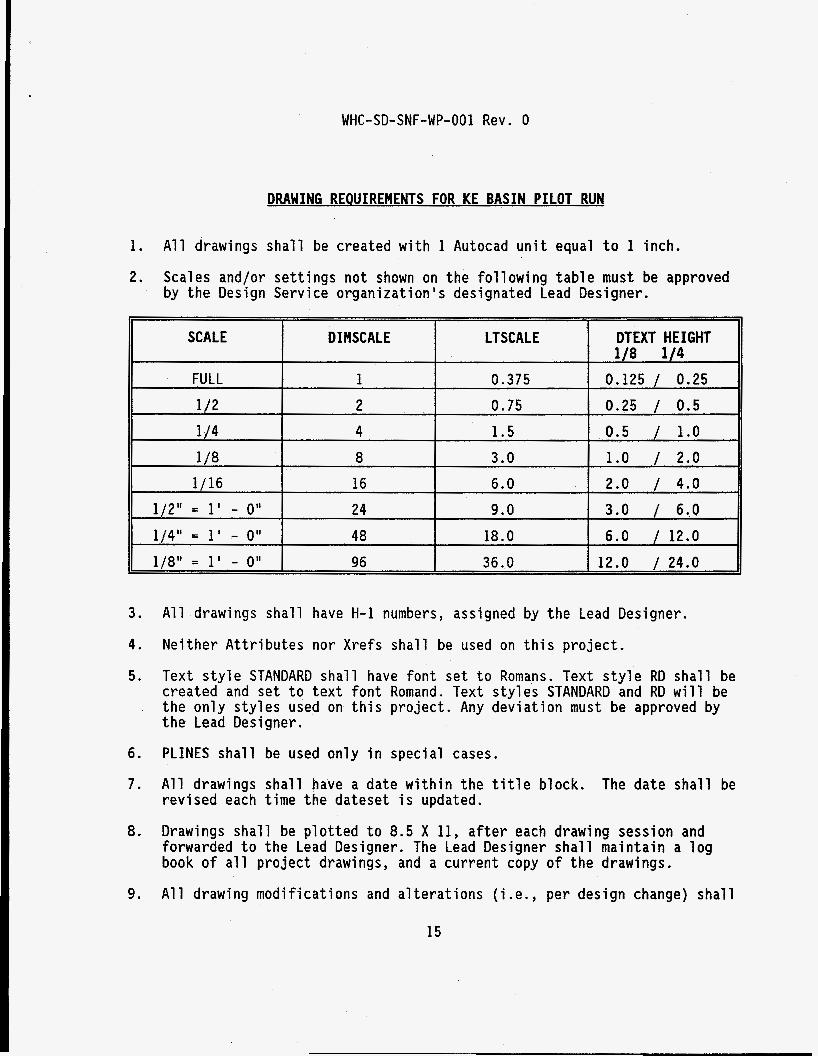
APPENDIX A: DRAWING REQUIREMENTS
14
WHC-SD-SNF-WP-001 Rev. 0
D I MSCALE LTSCALE SCALE
FULL
1 /2 1 /4 4 1.5
1 0.375 2 0.75
3.0 1 /8 8 1/16 16 6.0
1/21' = 1' - 0" 24 9.0 1/41' = 1' - o t t 48 18.0 1/811 = 1' - 0" 96 36.0
DRAWING REQUIREMENTS FOR KE BASIN PILOT RUN
DTEXT HEIGHT 118 114
0.125 / 0.25 0.25 / 0.5 0.5 / 1.0 1.0 / 2.0 2.0 / 4.0 3.0 / 6.0 6.0 / 12.0 12.0 / 24.0
1.
2.
A l l drawings s h a l l be created w i t h 1 Autocad un i t equal t o 1 inch.
Scales and/or se t t i ngs no t shown on the fo l l ow ing t a b l e must be approved by t h e Design Service organ iza t ion 's designated Lead Designer.
3.
4.
5.
A l l drawings sha l l have H-1 numbers, assigned by the Lead Designer.
Ne i ther A t t r i b u t e s nor Xrefs sha l l be used on t h i s p ro jec t .
Text s t y l e STANDARD s h a l l have fon t set t o Romans. Text s t y l e RD s h a l l be created and se t t o t e x t f o n t Romand. Text s t y l e s STANDARD and RD w i l l be the on ly s t y l e s used on t h i s p ro jec t . Any dev ia t i on must be approved by the Lead Designer.
6 . PLINES s h a l l be used on ly i n specia l cases.
7. A l l drawings s h a l l have a date w i t h i n the t i t l e block. The date s h a l l be rev i sed each t ime the dateset i s updated.
8. Drawings s h a l l be p l o t t e d t o 8.5 X 11, a f t e r each drawing session and forwarded t o the Lead Designer. The Lead Designer s h a l l ma in ta in a l o g book o f a l l p r o j e c t drawings, and a cur ren t copy o f the drawings.
9. A l l drawing mod i f i ca t ions and a l t e r a t i o n s ( i .e . , per design change) s h a l l
15
WHC-SD-SNF-WP-001 Rev. 0
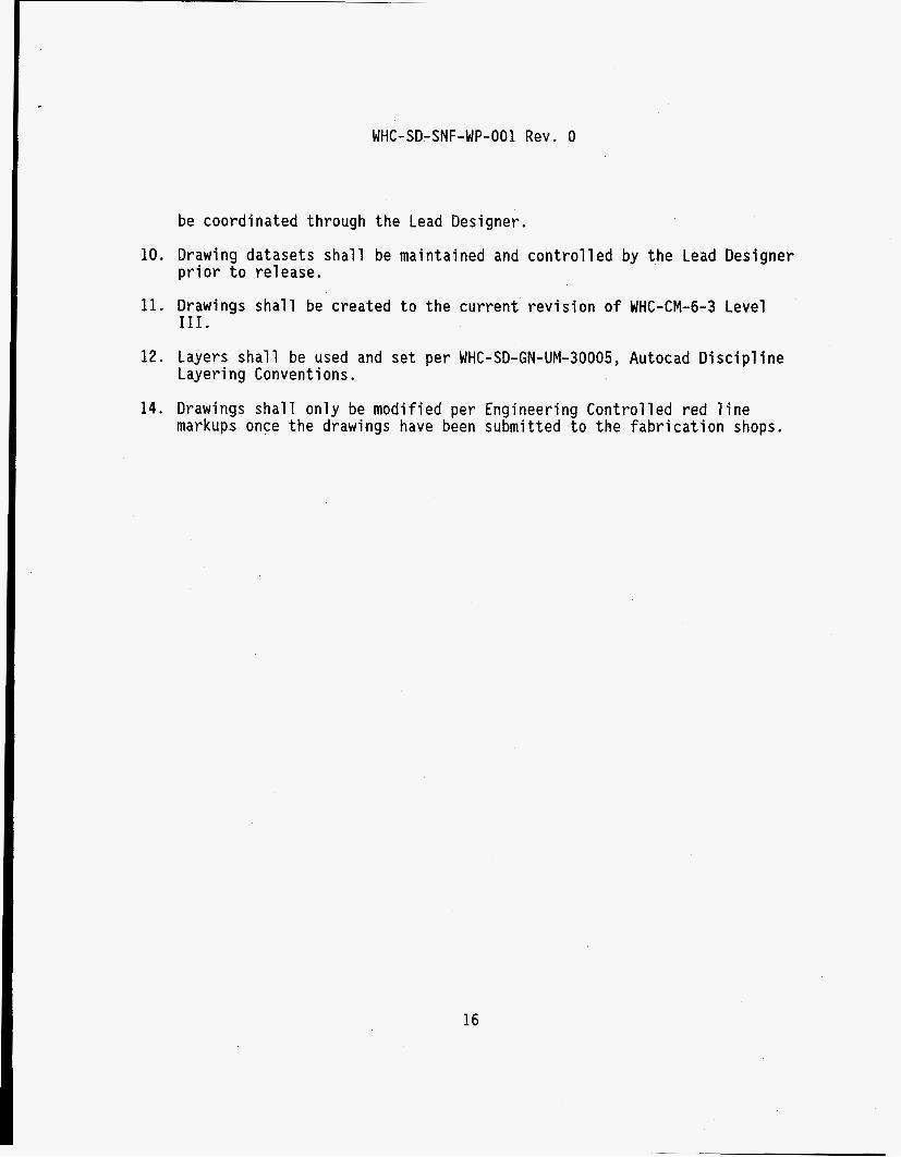
be coordinated through the Lead Designer.
10. Drawing datasets shall be maintained and controlled by the Lead Designer pri or to re1 ease.
11. Drawings shall be created to the current revision o f WHC-CM-6-3 Level 111.
12. Layers shall be used and set per WHC-SD-GN-UM-30005, Autocad Discipline Layering Conventions .
14. Drawings shall only be modified per Engineering Controlled red line markups once the drawings have been submitted to the fabrication shops.
16