Embed Size (px)
Citation preview
1
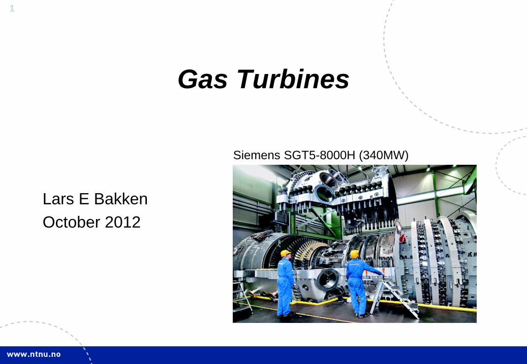
Gas Turbines
Lars E Bakken October 2012
Siemens SGT5-8000H (340MW)
2
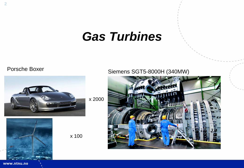
Gas Turbines
Øyvind Hundseid November 11, 2009
Siemens SGT5-8000H (340MW)
x 2000
Porsche Boxer
x 100
3
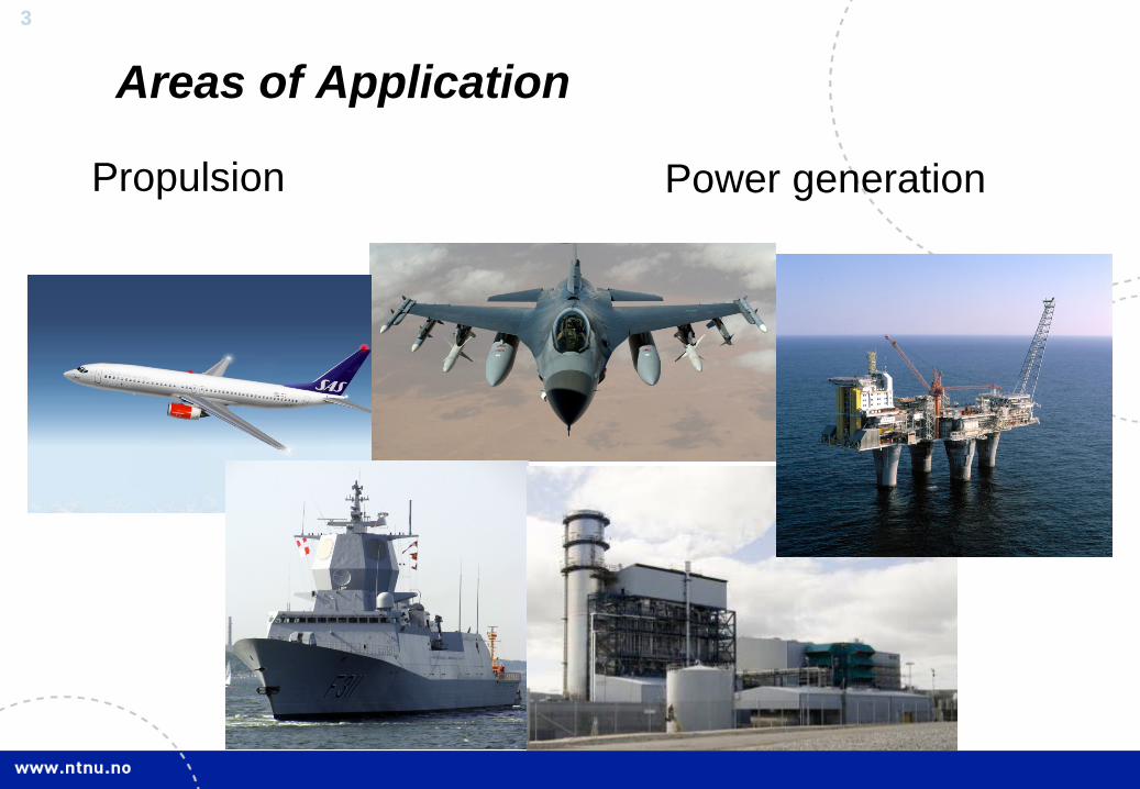
Areas of Application
Propulsion
Power generation
4
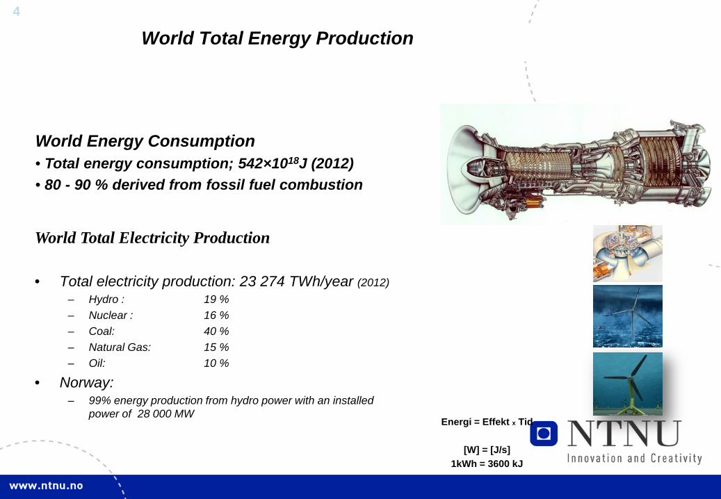
World Total Energy Production
World Total Electricity Production
• Total electricity production: 23 274 TWh/year (2012) – Hydro : 19 % – Nuclear : 16 % – Coal: 40 % – Natural Gas: 15 % – Oil: 10 %
• Norway: – 99% energy production from hydro power with an installed
power of 28 000 MW Energi = Effekt x Tid
[W] = [J/s]
1kWh = 3600 kJ
World Energy Consumption • Total energy consumption; 542×1018J (2012) • 80 - 90 % derived from fossil fuel combustion
5
5
0
1
2
3
4
1990 2000 2007 2015 2025 2035
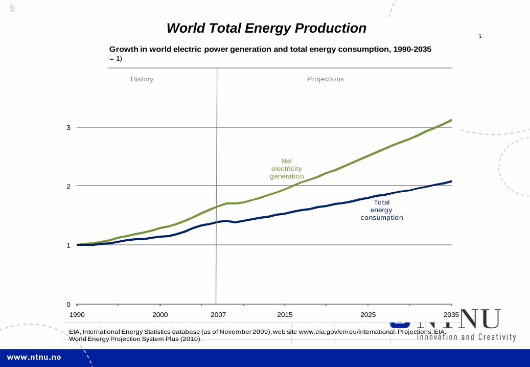
Figure 67. Growth in world electric power generation and total energy consumption, 1990-2035(index, 1990 = 1)
History Projections
Net electricity generation
Total energy
consumption
EIA, International Energy Statistics database (as of November 2009), web site www.eia.gov/emeu/international. Projections: EIA, World Energy Projection System Plus (2010).
World Total Energy Production
6
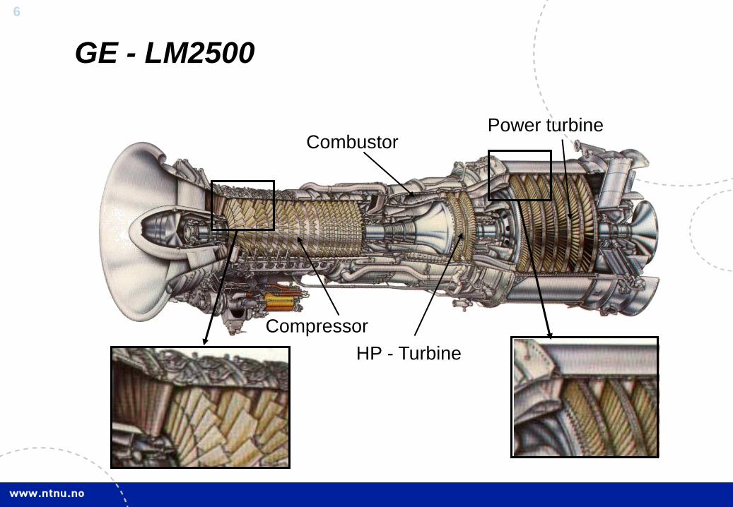
GE - LM2500
Compressor
Combustor Power turbine
HP - Turbine
7
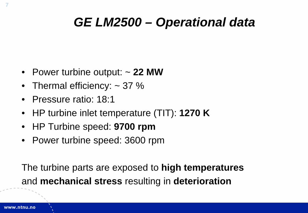
GE LM2500 – Operational data
• Power turbine output: ~ 22 MW • Thermal efficiency: ~ 37 % • Pressure ratio: 18:1 • HP turbine inlet temperature (TIT): 1270 K • HP Turbine speed: 9700 rpm • Power turbine speed: 3600 rpm The turbine parts are exposed to high temperatures and mechanical stress resulting in deterioration
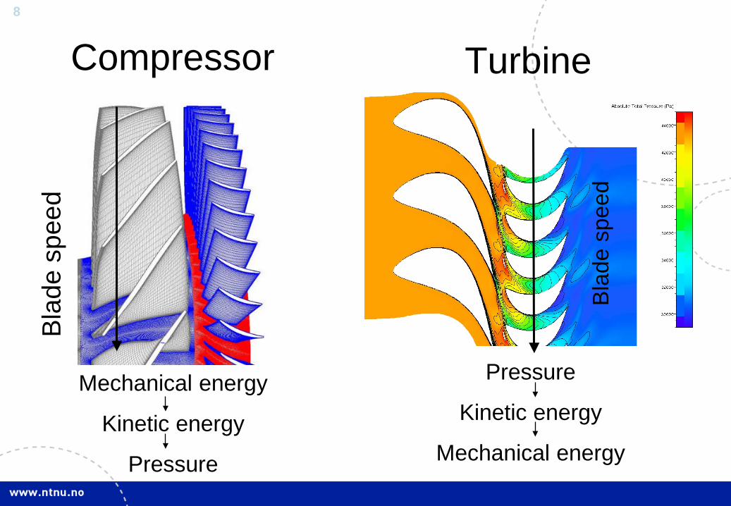
8
Turbine Bl
ade
spee
d Compressor
Mechanical energy
Kinetic energy
Pressure
Blad
e sp
eed
Pressure
Kinetic energy
Mechanical energy
9
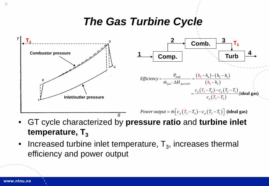
T3
Inlet/outler pressure
Combustor pressure
• GT cycle characterized by pressure ratio and turbine inlet temperature, T3
• Increased turbine inlet temperature, T3, increases thermal efficiency and power output
Comp.
Comb.
Turb 1 4
3 2 T3
The Gas Turbine Cycle
( ) ( )( )
( ) ( )( )
4 2 1
2
4 2 1
3
3 2
3
3 (
shaft
fuel fuel LHV
p p
p
P h h hEff
hh
T
iciencym H h
c T cc T
T TT
− − −= =
⋅∆ −
− − −=
− ideal gas)
( ) ( )4 2 13p pPower output m c T c T TT = − − − (ideal gas)
10
-100,000
100,000
300,000
500,000
700,000
900,000
1 100,000
1 300,000
1 500,000
5,200 5,400 5,600 5,800 6,000 6,200 6,400 6,600
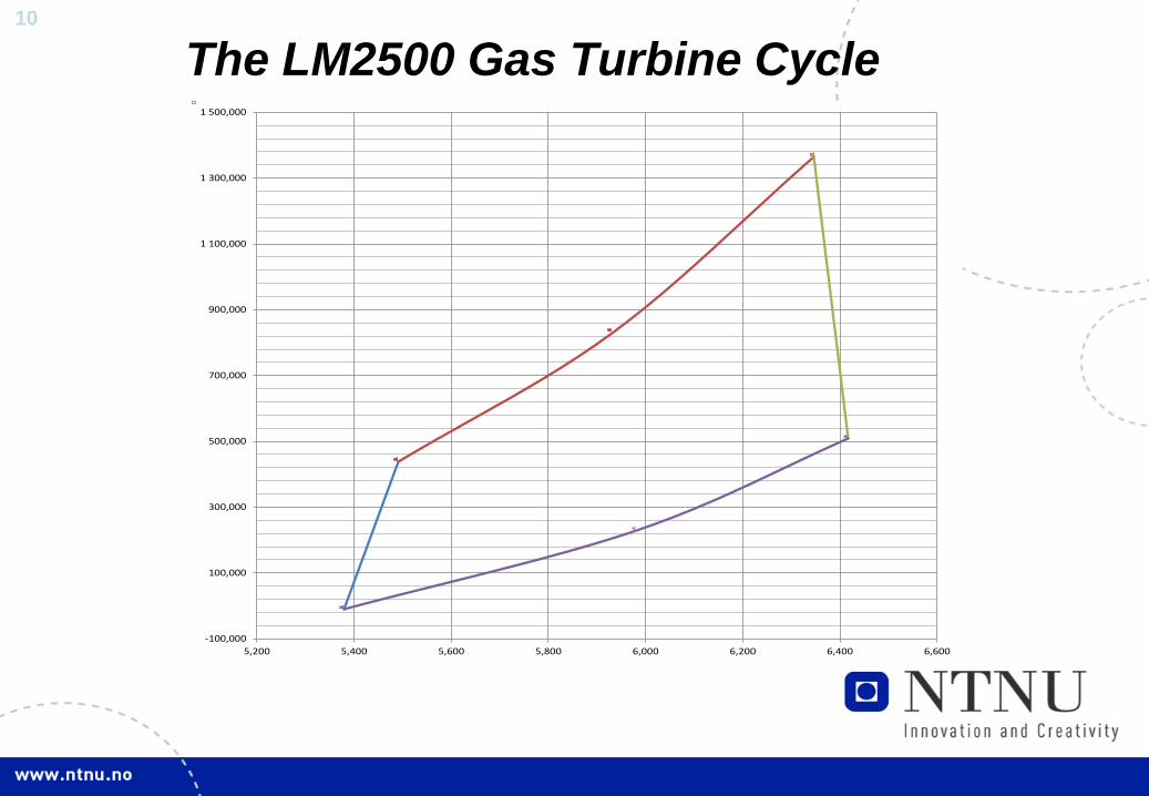
The LM2500 Gas Turbine Cycle
11
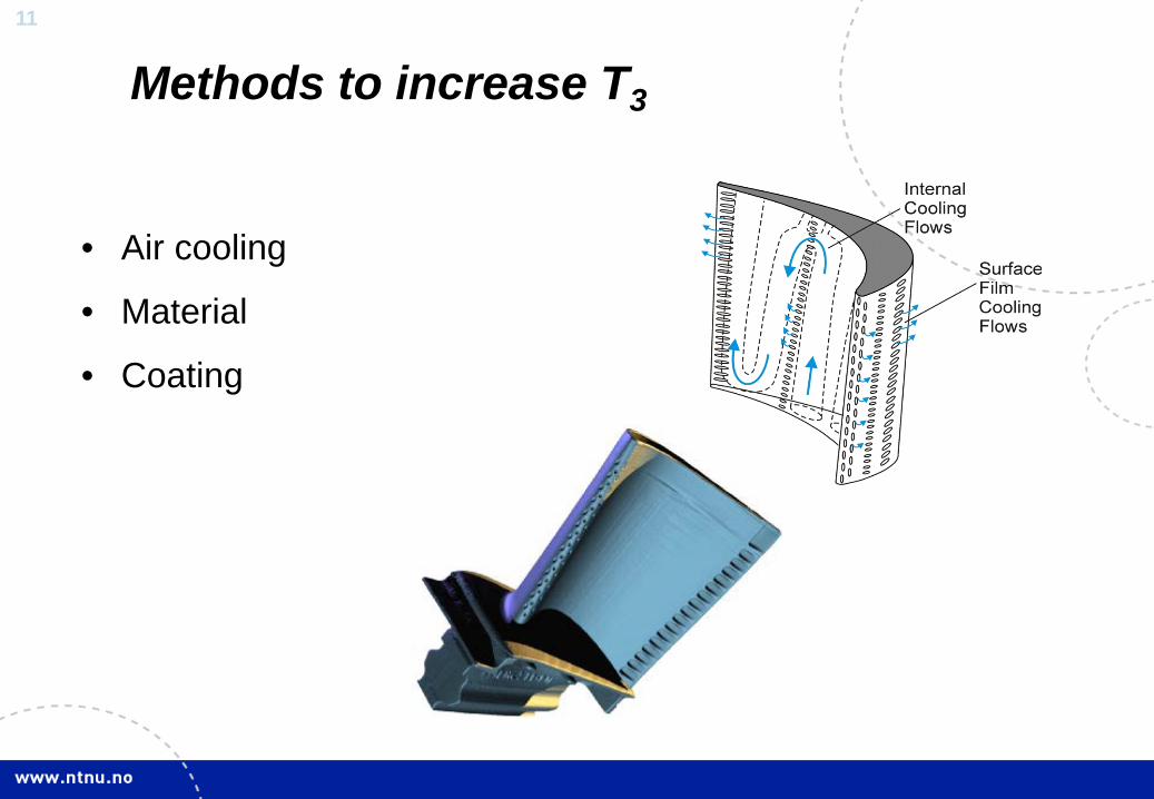
• Air cooling
• Material
• Coating
Methods to increase T3
12
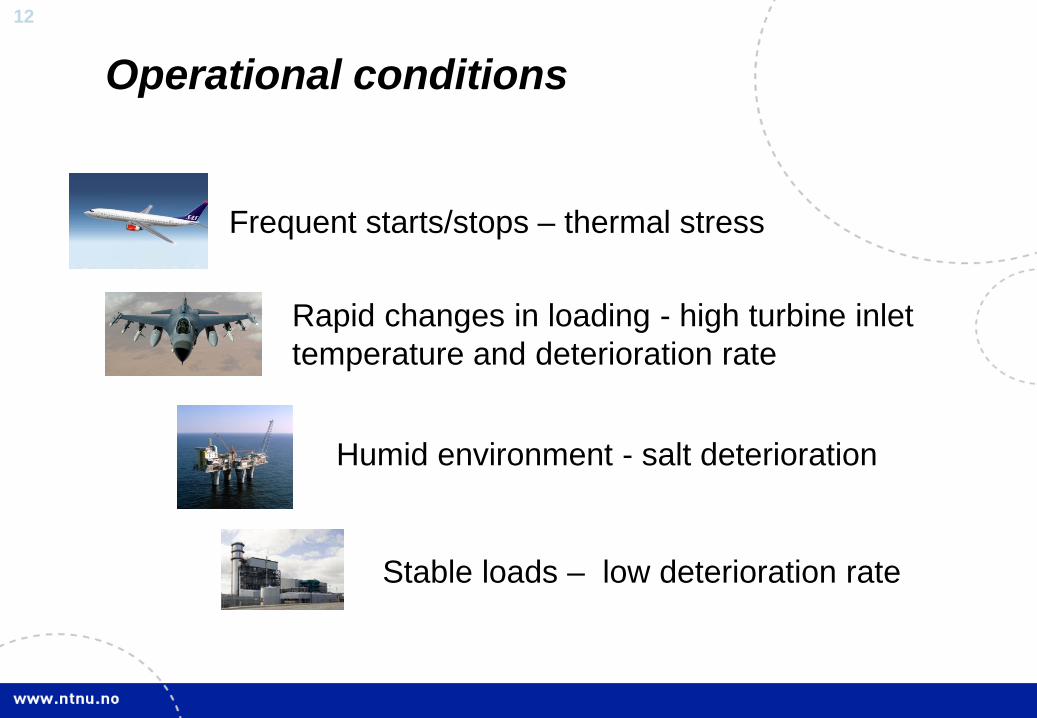
Operational conditions
Frequent starts/stops – thermal stress
Rapid changes in loading - high turbine inlet temperature and deterioration rate
Humid environment - salt deterioration
Stable loads – low deterioration rate
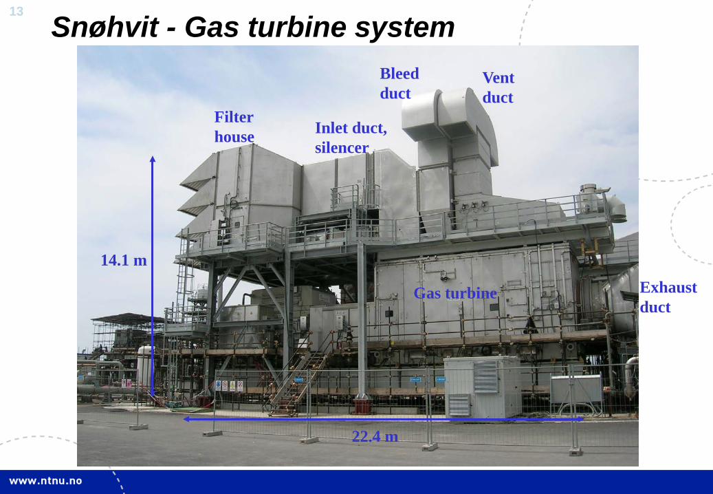
13 Snøhvit - Gas turbine system
Filter house Inlet duct,
silencer
Gas turbine Exhaust duct
Bleed duct
Vent duct
14.1 m
22.4 m
14
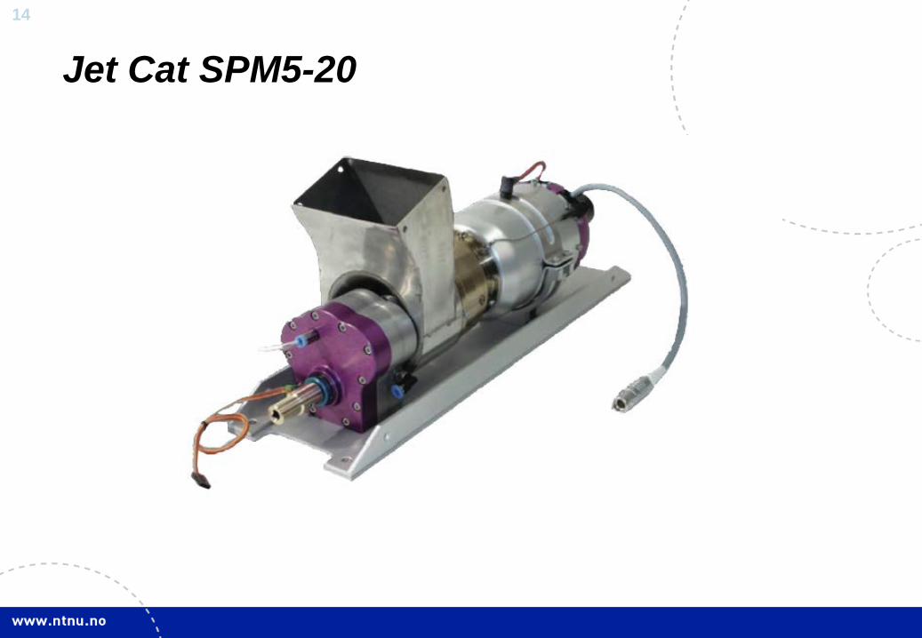
Jet Cat SPM5-20
15
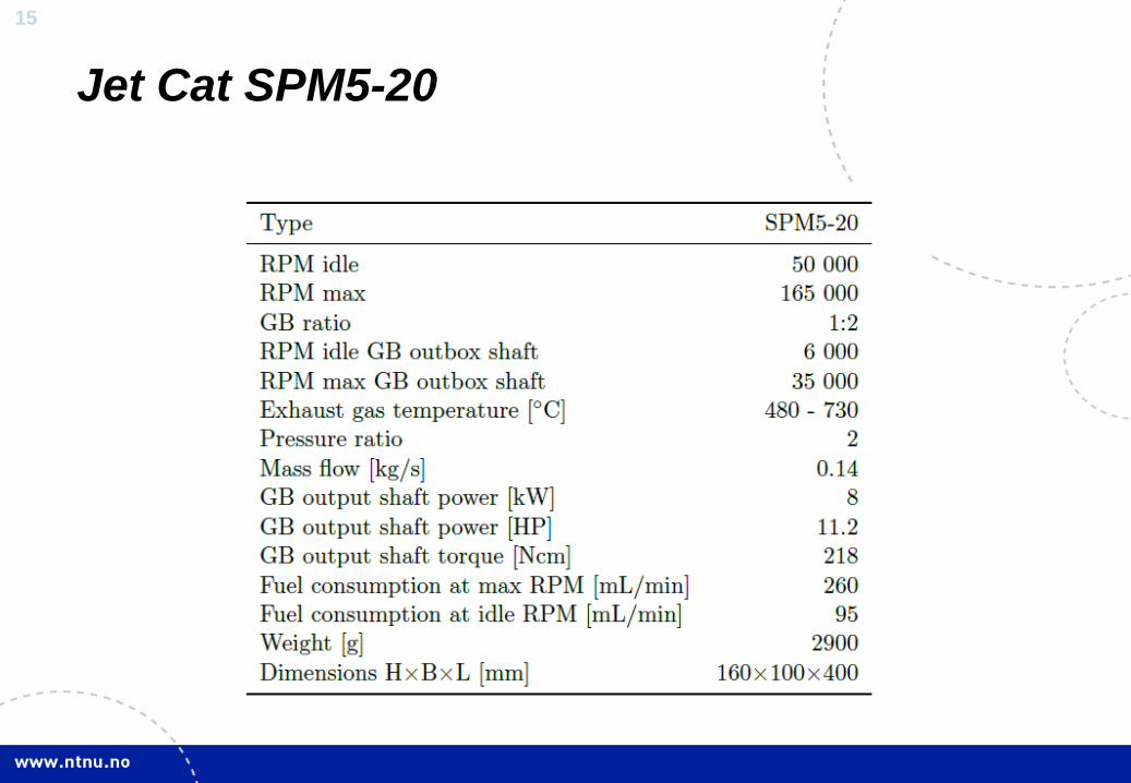
Jet Cat SPM5-20
16
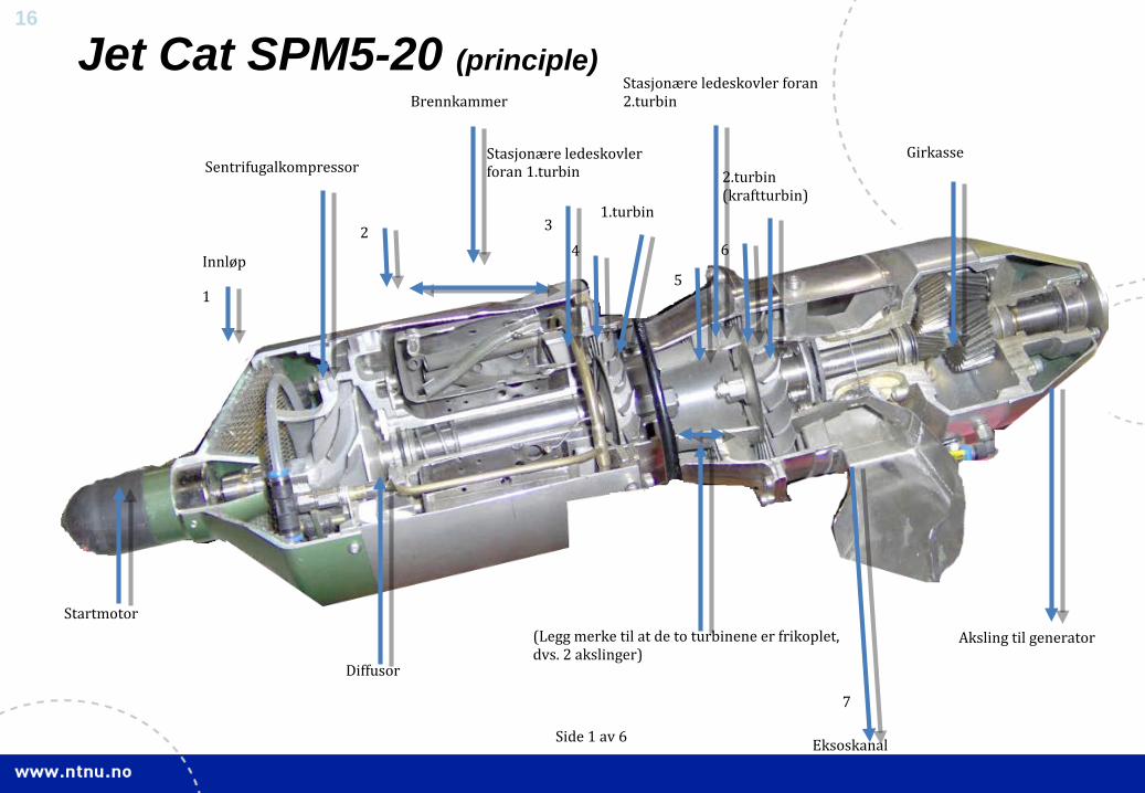
Jet Cat SPM5-20 (principle)
Side 1 av 6
1
2 3 4
5
6
7
Startmotor
Innløp
Sentrifugalkompressor
Diffusor
Brennkammer
Stasjonære ledeskovler foran 1.turbin
1.turbin
(Legg merke til at de to turbinene er frikoplet, dvs. 2 akslinger)
Stasjonære ledeskovler foran 2.turbin
2.turbin (kraftturbin)
Eksoskanal
Girkasse
Aksling til generator
17
Jet Cat SPM5-20
1 6
�7
2
5 3
4
abe
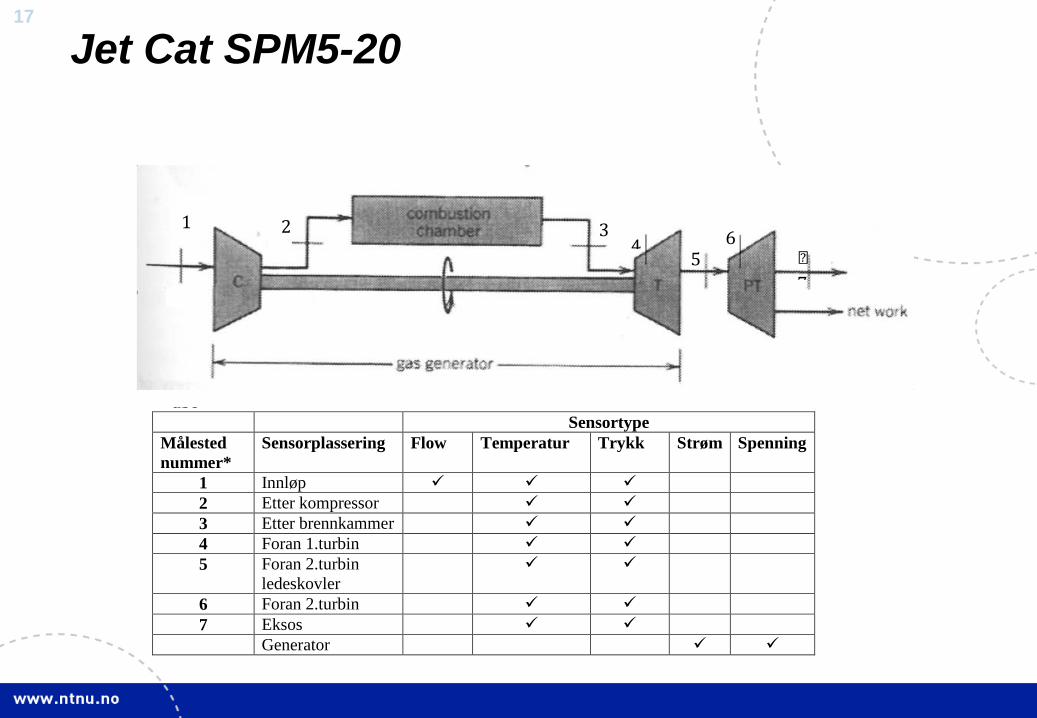
Sensortype Målested nummer*
Sensorplassering Flow Temperatur Trykk Strøm Spenning
1 Innløp 2 Etter kompressor 3 Etter brennkammer 4 Foran 1.turbin 5 Foran 2.turbin
ledeskovler
6 Foran 2.turbin 7 Eksos Generator

18
JetMan