Embed Size (px)
Citation preview
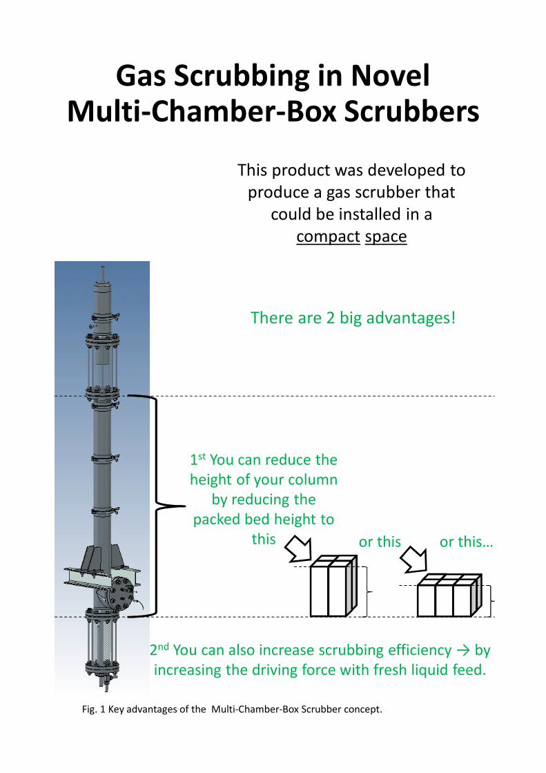
Gas Scrubbing in NovelMulti-Chamber-Box Scrubbers
This product was developed to produce a gas scrubber that
could be installed in acompact space
1st You can reduce the height of your column
by reducing the packed bed height to
this or this
Fig. 1 Key advantages of the Multi-Chamber-Box Scrubber concept.
or this…
2nd You can also increase scrubbing efficiency → by increasing the driving force with fresh liquid feed.
There are 2 big advantages!
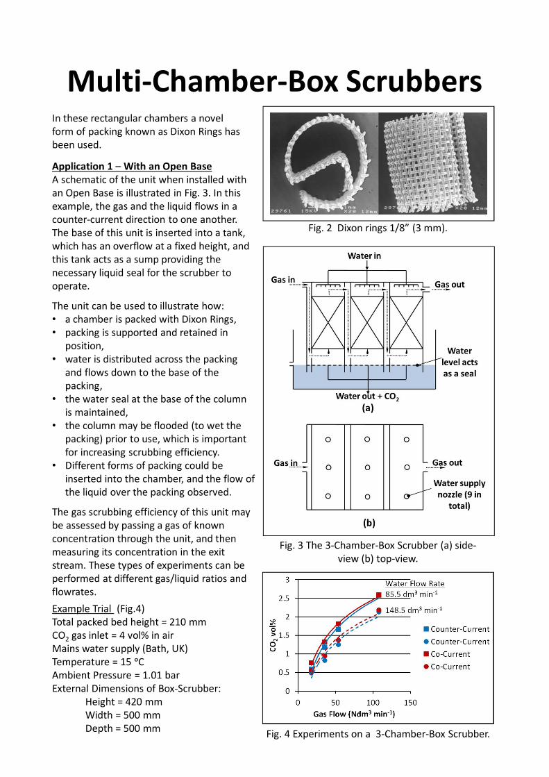
Multi-Chamber-Box ScrubbersIn these rectangular chambers a novel form of packing known as Dixon Rings has been used.
Fig. 2 Dixon rings 1/8” (3 mm).
Application 1 – With an Open BaseA schematic of the unit when installed with an Open Base is illustrated in Fig. 3. In this example, the gas and the liquid flows in a counter-current direction to one another. The base of this unit is inserted into a tank, which has an overflow at a fixed height, and this tank acts as a sump providing the necessary liquid seal for the scrubber to operate.
The unit can be used to illustrate how: • a chamber is packed with Dixon Rings, • packing is supported and retained in
position, • water is distributed across the packing
and flows down to the base of the packing,
• the water seal at the base of the column is maintained,
• the column may be flooded (to wet the packing) prior to use, which is important for increasing scrubbing efficiency.
• Different forms of packing could be inserted into the chamber, and the flow of the liquid over the packing observed.
The gas scrubbing efficiency of this unit may be assessed by passing a gas of known concentration through the unit, and then measuring its concentration in the exit stream. These types of experiments can be performed at different gas/liquid ratios and flowrates.Example Trial (Fig.4)Total packed bed height = 210 mmCO2 gas inlet = 4 vol% in airMains water supply (Bath, UK)Temperature = 15 ᵒCAmbient Pressure = 1.01 barExternal Dimensions of Box-Scrubber:
Height = 420 mmWidth = 500 mmDepth = 500 mm Fig. 4 Experiments on a 3-Chamber-Box Scrubber.
Fig. 3 The 3-Chamber-Box Scrubber (a) side-view (b) top-view.
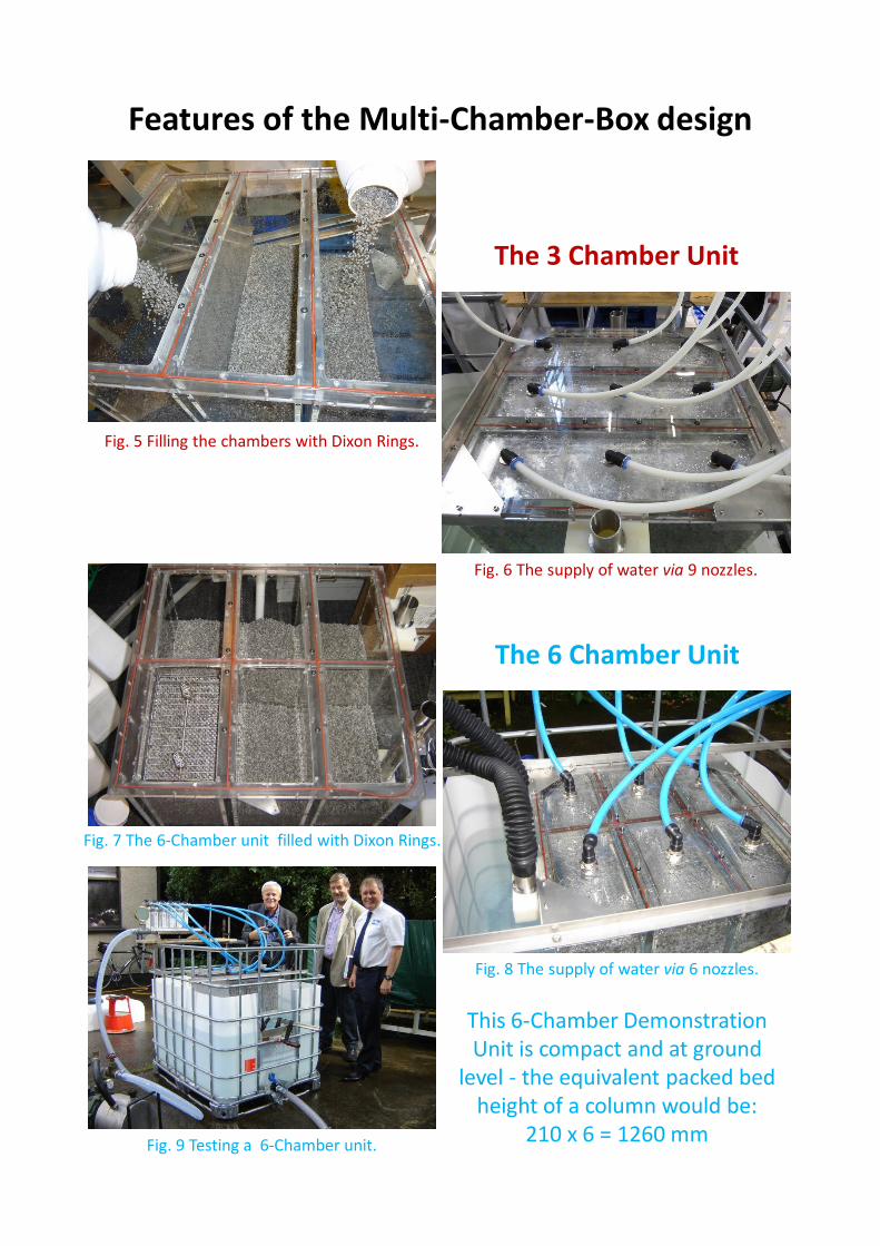
Features of the Multi-Chamber-Box design
Fig. 5 Filling the chambers with Dixon Rings.
Fig. 6 The supply of water via 9 nozzles.
Fig. 8 The supply of water via 6 nozzles.
Fig. 9 Testing a 6-Chamber unit.
The 3 Chamber Unit
The 6 Chamber Unit
This 6-Chamber Demonstration Unit is compact and at ground
level - the equivalent packed bed height of a column would be:
210 x 6 = 1260 mm
Fig. 7 The 6-Chamber unit filled with Dixon Rings.
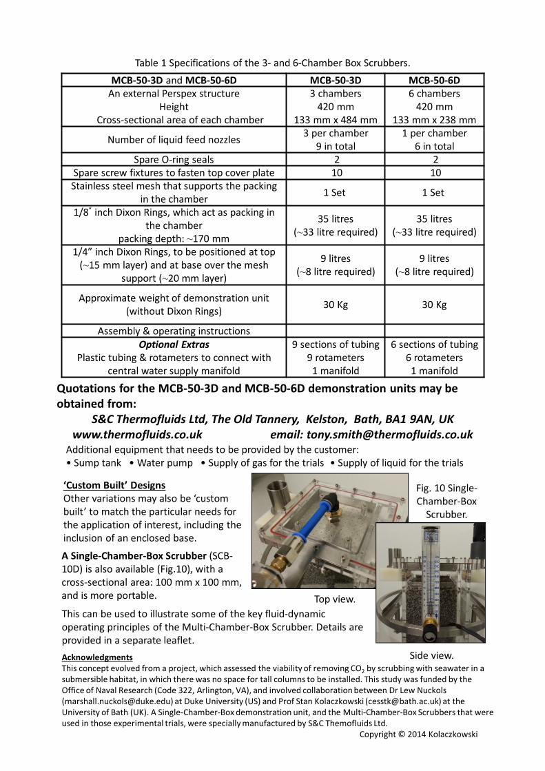
MCB-50-3D and MCB-50-6D MCB-50-3D MCB-50-6DAn external Perspex structure
HeightCross-sectional area of each chamber
3 chambers420 mm
133 mm x 484 mm
6 chambers420 mm
133 mm x 238 mm
Number of liquid feed nozzles 3 per chamber9 in total
1 per chamber6 in total
Spare O-ring seals 2 2Spare screw fixtures to fasten top cover plate 10 10Stainless steel mesh that supports the packing
in the chamber 1 Set 1 Set
1/8” inch Dixon Rings, which act as packing in the chamber
packing depth: ~170 mm
35 litres(~33 litre required)
35 litres(~33 litre required)
1/4” inch Dixon Rings, to be positioned at top (~15 mm layer) and at base over the mesh
support (~20 mm layer)
9 litres(~8 litre required)
9 litres(~8 litre required)
Approximate weight of demonstration unit (without Dixon Rings) 30 Kg 30 Kg
Assembly & operating instructionsOptional Extras
Plastic tubing & rotameters to connect with central water supply manifold
9 sections of tubing9 rotameters
1 manifold
6 sections of tubing6 rotameters
1 manifold
‘Custom Built’ DesignsOther variations may also be ‘custom built’ to match the particular needs for the application of interest, including the inclusion of an enclosed base.
AcknowledgmentsThis concept evolved from a project, which assessed the viability of removing CO2 by scrubbing with seawater in a submersible habitat, in which there was no space for tall columns to be installed. This study was funded by the Office of Naval Research (Code 322, Arlington, VA), and involved collaboration between Dr Lew Nuckols([email protected]) at Duke University (US) and Prof Stan Kolaczkowski ([email protected]) at the University of Bath (UK). A Single-Chamber-Box demonstration unit, and the Multi-Chamber-Box Scrubbers that were used in those experimental trials, were specially manufactured by S&C Themofluids Ltd.
Copyright © 2014 Kolaczkowski
Quotations for the MCB-50-3D and MCB-50-6D demonstration units may be obtained from:
S&C Thermofluids Ltd, The Old Tannery, Kelston, Bath, BA1 9AN, UKwww.thermofluids.co.uk email: [email protected]
Table 1 Specifications of the 3- and 6-Chamber Box Scrubbers.
Additional equipment that needs to be provided by the customer:• Sump tank • Water pump • Supply of gas for the trials • Supply of liquid for the trials
Fig. 10 Single-Chamber-Box
Scrubber.
Side view.
Top view.
A Single-Chamber-Box Scrubber (SCB-10D) is also available (Fig.10), with a cross-sectional area: 100 mm x 100 mm, and is more portable.
This can be used to illustrate some of the key fluid-dynamic operating principles of the Multi-Chamber-Box Scrubber. Details are provided in a separate leaflet.


![HP Image Zone Print Job [12/30/2008 11:19 AM 1.750] · Venturi Scrubbing/Mist Elimination D.R. Technology builds both venturi scrubbers and associated systems which include mist eliminators](https://img.pdfslide.us/doc/110x75/5e6f8c18e89448030635a7a1/hp-image-zone-print-job-12302008-1119-am-1750-venturi-scrubbingmist-elimination.jpg)