Embed Size (px)
Citation preview
© 2011, Maxitrol Company. All Rights Reserved.1
Gas Pressure Regulators CatalogFor Industrial Engines and Generator Sets
© 2011, Maxitrol Company. All Rights Reserved.2
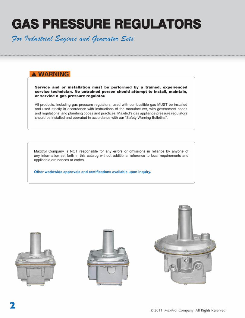
GAS PRESSURE REGULATORSFor Industrial Engines and Generator Sets
Service and or installation must be performed by a trained, experienced service technician. No untrained person should attempt to install, maintain, or service a gas pressure regulator.
All products, including gas pressure regulators, used with combustible gas MUST be installed and used strictly in accordance with instructions of the manufacturer, with government codes and regulations, and plumbing codes and practices. Maxitrol’s gas appliance pressure regulators should be installed and operated in accordance with our “Safety Warning Bulletins”.
Maxitrol Company is NOT responsible for any errors or omissions in reliance by anyone of any information set forth in this catalog without additional reference to local requirements and applicable ordinances or codes.
Other worldwide approvals and certifications available upon inquiry.
© 2011, Maxitrol Company. All Rights Reserved.3
Table of Contents
RV Series - Straight-Thru-Flow Design Description ............................................................................................................................ 4 Specifications.........................................................................................................................4 Certifications..........................................................................................................................5 PressureTap IdentificationNumbers ....................................................................................6 Capacities ............................................................................................................................. 6 Spring Selection Charts ......................................................................................................... 7 Dimensions ........................................................................................................................... 8 Cutaway w/Callouts ............................................................................................................... 9 Pressure Drop Chart ............................................................................................................ 22
R/RS Series - Balanced Valve Design Description ........................................................................................................................... 10 Specifications........................................................................................................................10 Certifications........................................................................................................................11 PressureTapIdentificationNumbers....................................................................................12 Capacities ............................................................................................................................. 12 Spring Selection Charts ......................................................................................................... 13 Dimensions ........................................................................................................................... 14 Cutawayw/Callouts ............................................................................................................15 Pressure Drop Chart ............................................................................................................ 23
210 Series - Balanced Valve Design Description...........................................................................................................................16 Specifications........................................................................................................................16 Certifications........................................................................................................................17 PressureTapIdentificationNumbers.....................................................................................18 Capacities ............................................................................................................................. 18 Spring Selection Charts ......................................................................................................... 19 Dimensions .......................................................................................................................... 20 Cutaway w/Callouts ............................................................................................................ 21 Pressure Drop Chart ............................................................................................................. 24
© 2011, Maxitrol Company. All Rights Reserved.4
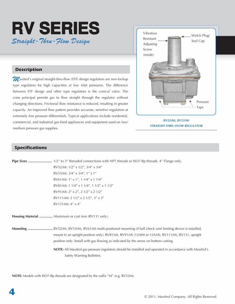
RV52(M), RV53(M)
STRAIGHT-THRU-FLOW REGULATOR
Description
Maxitrol’soriginalstraight-thru-flow(STF)designregulatorsarenon-lockup
type regulators for high capacities at low inlet pressures. The difference
between STF design and other type regulators is the conical valve. The
cone principal permits gas to flow straight through the regulator without
changingdirections.Frictionalflowresistanceisreduced,resultingingreater
capacity.Animprovedflowpatternprovidesaccurate,sensitiveregulationat
extremely low pressure differentials. Typical applications include residential,
commercial,andindustrialgas-firedappliancesandequipmentusedonlow/
medium pressure gas supplies.
RV SERIESStraight-Thru-Flow Design
Specifications
VibrationResistantAdjusting Screw(inside)
Welch Plug/ Seal Cap
Pressure Taps
Pipe Sizes ......................... 1/2”to3”threadedconnectionswithNPTthreadsorISO7-Rpthreads.4”Flangeonly.
RV52(M):1/2”x1/2”,3/4”x3/4”
RV53(M):3/4”x3/4”,1”x1”
RV61(M):1”x1”,11/4”x11/4”
RV81(M):11/4”x11/4”,11/2”x11/2”
RV91(M):2”x2”,21/2”x21/2”
RV111(M):21/2”x21/2”,3”x3”
RV131(M):4”x4”
Housing Material .............. Aluminumorcastiron(RV131only).
Mounting .......................... RV52(M),RV53(M),RV61(M)multi-positionalmounting(ifballcheckventlimitingdeviceisinstalled,
mountinanuprightpositiononly).RV81(M),RV91(M)(12A04or12A34),RV111(M),RV131,upright
positiononly.Installwithgasflowingasindicatedbythearrowonbottomcasting.
NOTE: AllMaxitrolgaspressureregulatorsshouldbeinstalledandoperatedinaccordancewithMaxitrol’s
Safety Warning Bulletins.
NOTE: ModelswithISO7-Rpthreadsaredesignatedbythesuffix“M”(e.g.RV52M).
© 2011, Maxitrol Company. All Rights Reserved.5
Gas Pressure Regulators for Industrial Engines & Generator Sets
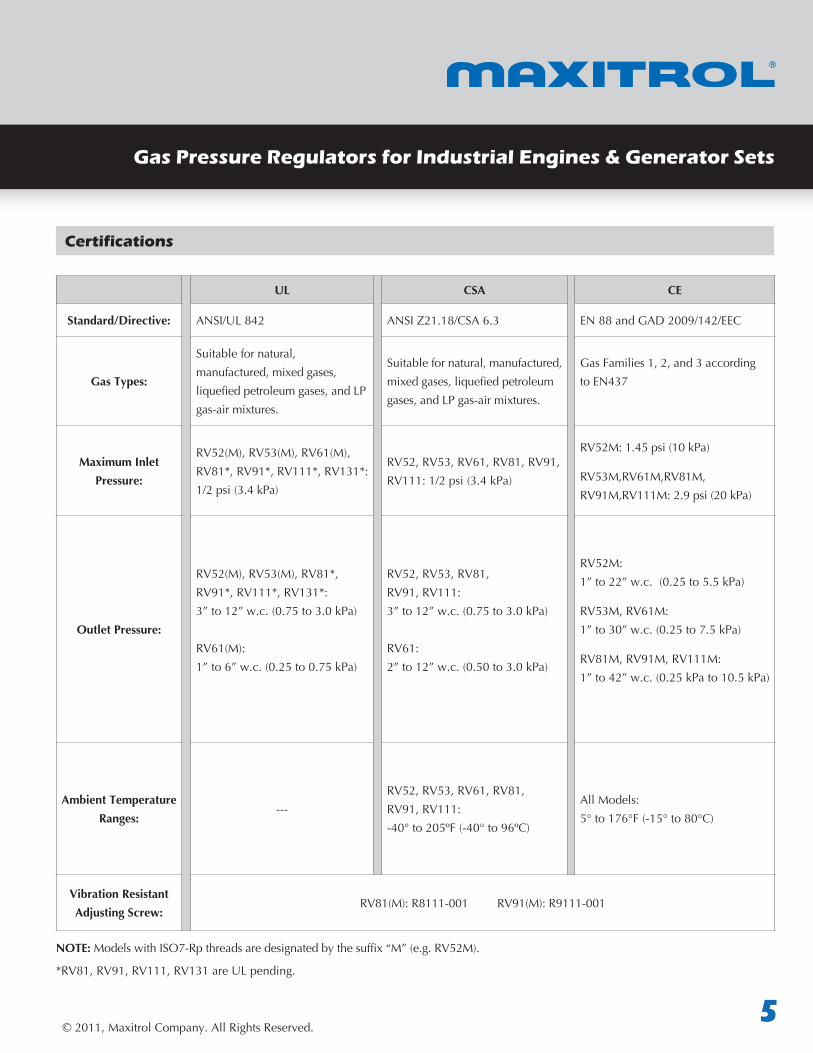
UL CSA CE
Standard/Directive: ANSI/UL842 ANSIZ21.18/CSA6.3 EN88andGAD2009/142/EEC
Gas Types:
Suitablefornatural,manufactured, mixed gases, liquefiedpetroleumgases,andLPgas-air mixtures.
Suitablefornatural,manufactured,mixedgases,liquefiedpetroleumgases,andLPgas-airmixtures.
GasFamilies1,2,and3accordingtoEN437
Maximum Inlet Pressure:
RV52(M),RV53(M),RV61(M),RV81*,RV91*,RV111*,RV131*:1/2psi(3.4kPa)
RV52,RV53,RV61,RV81,RV91,RV111:1/2psi(3.4kPa)
RV52M:1.45psi(10kPa)
RV53M,RV61M,RV81M,RV91M,RV111M:2.9psi(20kPa)
Outlet Pressure:
RV52(M),RV53(M),RV81*,RV91*,RV111*,RV131*:3”to12”w.c.(0.75to3.0kPa)
RV61(M):1”to6”w.c.(0.25to0.75kPa)
RV52,RV53,RV81,RV91,RV111:3”to12”w.c.(0.75to3.0kPa)
RV61:2”to12”w.c.(0.50to3.0kPa)
RV52M:1”to22”w.c.(0.25to5.5kPa)
RV53M,RV61M:1”to30”w.c.(0.25to7.5kPa)
RV81M,RV91M,RV111M:1”to42”w.c.(0.25kPato10.5kPa)
Ambient Temperature Ranges:
---RV52,RV53,RV61,RV81,RV91,RV111:-40°to205ºF(-40°to96ºC)
AllModels:5°to176°F(-15°to80°C)
Vibration Resistant Adjusting Screw:
RV81(M):R8111-001RV91(M):R9111-001
NOTE: ModelswithISO7-Rpthreadsaredesignatedbythesuffix“M”(e.g.RV52M).
*RV81,RV91,RV111,RV131areULpending.
Certifications
© 2011, Maxitrol Company. All Rights Reserved.6
RV SERIESStraight-Thru-Flow Design
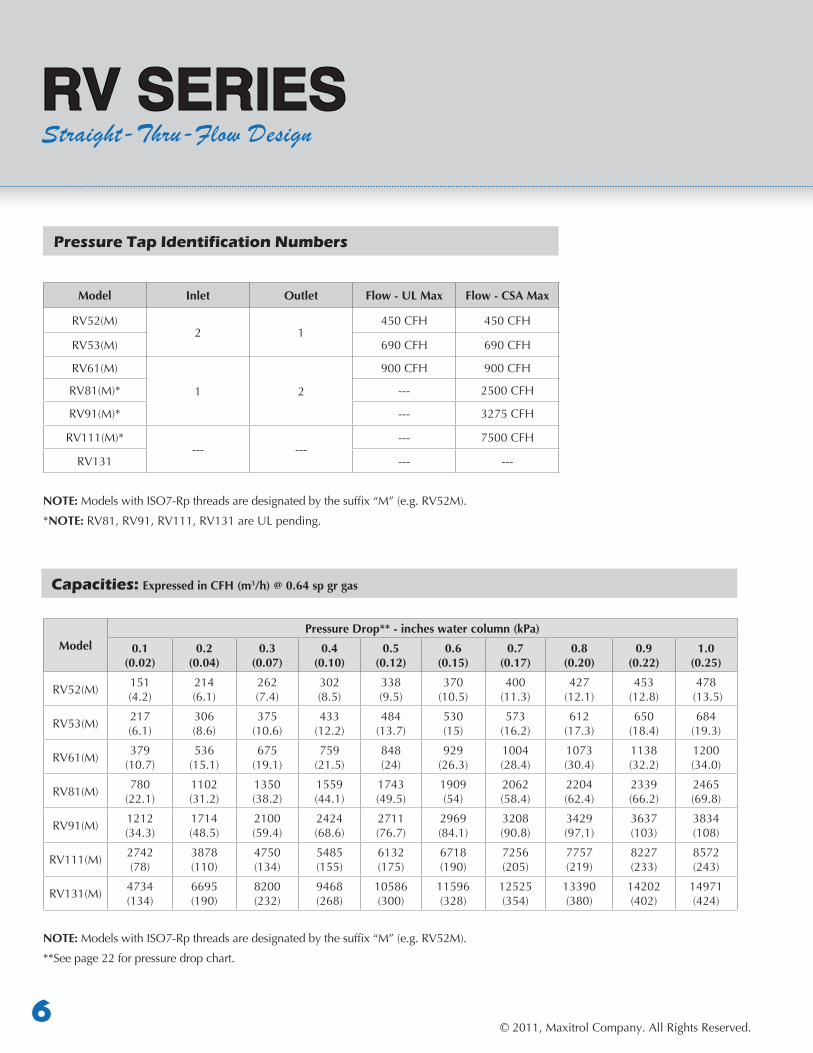
ModelPressure Drop** - inches water column (kPa)
0.1(0.02)
0.2(0.04)
0.3(0.07)
0.4(0.10)
0.5 (0.12)
0.6(0.15)
0.7(0.17)
0.8(0.20)
0.9(0.22)
1.0(0.25)
RV52(M) 151(4.2)
214 (6.1)
262(7.4)
302 (8.5)
338 (9.5)
370 (10.5)
400 (11.3)
427 (12.1)
453(12.8)
478(13.5)
RV53(M) 217 (6.1)
306(8.6)
375(10.6)
433(12.2)
484(13.7)
530(15)
573(16.2)
612(17.3)
650(18.4)
684(19.3)
RV61(M) 379 (10.7)
536(15.1)
675(19.1)
759(21.5)
848 (24)
929 (26.3)
1004 (28.4)
1073 (30.4)
1138 (32.2)
1200 (34.0)
RV81(M) 780 (22.1)
1102 (31.2)
1350(38.2)
1559(44.1)
1743 (49.5)
1909 (54)
2062(58.4)
2204 (62.4)
2339 (66.2)
2465(69.8)
RV91(M) 1212 (34.3)
1714 (48.5)
2100 (59.4)
2424 (68.6)
2711 (76.7)
2969(84.1)
3208 (90.8)
3429 (97.1)
3637(103)
3834 (108)
RV111(M) 2742 (78)
3878 (110)
4750(134)
5485(155)
6132(175)
6718(190)
7256(205)
7757(219)
8227(233)
8572(243)
RV131(M) 4734(134)
6695(190)
8200(232)
9468(268)
10586(300)
11596(328)
12525(354)
13390(380)
14202(402)
14971(424)
NOTE: ModelswithISO7-Rpthreadsaredesignatedbythesuffix“M”(e.g.RV52M).
**See page 22 for pressure drop chart.
Pressure Tap Identification Numbers
Capacities: Expressed in CFH (m3/h) @ 0.64 sp gr gas
Model Inlet Outlet Flow - UL Max Flow - CSA Max
RV52(M)2 1
450CFH 450CFH
RV53(M) 690CFH 690CFH
RV61(M)
1 2
900CFH 900CFH
RV81(M)* --- 2500CFH
RV91(M)* --- 3275CFH
RV111(M)*--- ---
--- 7500CFH
RV131 --- ---
NOTE: ModelswithISO7-Rpthreadsaredesignatedbythesuffix“M”(e.g.RV52M).
*NOTE: RV81,RV91,RV111,RV131areULpending.
© 2011, Maxitrol Company. All Rights Reserved.7
Gas Pressure Regulators for Industrial Engines & Generator Sets
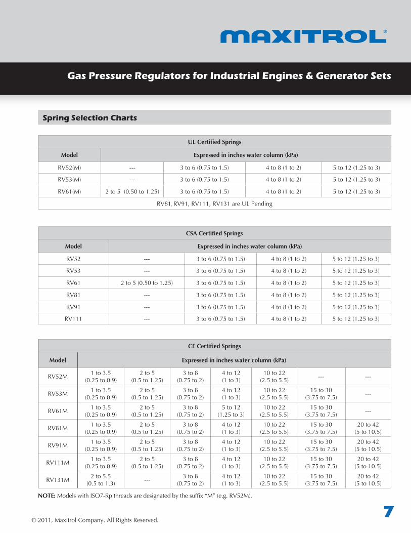
UL Certified Springs
Model Expressed in inches water column (kPa)
RV52(M) --- 3to6(0.75to1.5) 4to8(1to2) 5to12(1.25to3)
RV53(M) --- 3to6(0.75to1.5) 4to8(1to2) 5to12(1.25to3)
RV61(M) 2to5(0.50to1.25) 3to6(0.75to1.5) 4to8(1to2) 5to12(1.25to3)
RV81, RV91,RV111,RV131areULPending
Spring Selection Charts
CE Certified Springs
Model Expressed in inches water column (kPa)
RV52M 1to3.5(0.25to0.9)
2to5(0.5to1.25)
3 to 8(0.75to2)
4 to 12(1to3)
10 to 22(2.5to5.5) --- ---
RV53M 1to3.5(0.25to0.9)
2to5(0.5to1.25)
3 to 8(0.75to2)
4 to 12(1to3)
10 to 22(2.5to5.5)
15to30(3.75to7.5) ---
RV61M 1to3.5(0.25to0.9)
2to5(0.5to1.25)
3 to 8(0.75to2)
5to12(1.25to3)
10 to 22(2.5to5.5)
15to30(3.75to7.5) ---
RV81M 1to3.5(0.25to0.9)
2to5(0.5to1.25)
3 to 8(0.75to2)
4 to 12(1to3)
10 to 22(2.5to5.5)
15to30(3.75to7.5)
20 to 42(5to10.5)
RV91M 1to3.5(0.25to0.9)
2to5(0.5to1.25)
3 to 8(0.75to2)
4 to 12(1to3)
10 to 22(2.5to5.5)
15to30(3.75to7.5)
20 to 42(5to10.5)
RV111M 1to3.5(0.25to0.9)
2to5(0.5to1.25)
3 to 8(0.75to2)
4 to 12(1to3)
10 to 22(2.5to5.5)
15to30(3.75to7.5)
20 to 42(5to10.5)
RV131M 2to5.5(0.5to1.3) --- 3 to 8
(0.75to2)4 to 12(1to3)
10 to 22(2.5to5.5)
15to30(3.75to7.5)
20 to 42(5to10.5)
NOTE: ModelswithISO7-Rpthreadsaredesignatedbythesuffix“M”(e.g.RV52M).
CSA Certified Springs
Model Expressed in inches water column (kPa)
RV52 --- 3to6(0.75to1.5) 4to8(1to2) 5to12(1.25to3)
RV53 --- 3to6(0.75to1.5) 4to8(1to2) 5to12(1.25to3)
RV61 2to5(0.50to1.25) 3to6(0.75to1.5) 4to8(1to2) 5to12(1.25to3)
RV81 --- 3to6(0.75to1.5) 4to8(1to2) 5to12(1.25to3)
RV91 --- 3to6(0.75to1.5) 4to8(1to2) 5to12(1.25to3)
RV111 --- 3to6(0.75to1.5) 4to8(1to2) 5to12(1.25to3)
© 2011, Maxitrol Company. All Rights Reserved.8
RV SERIESStraight-Thru-Flow Design
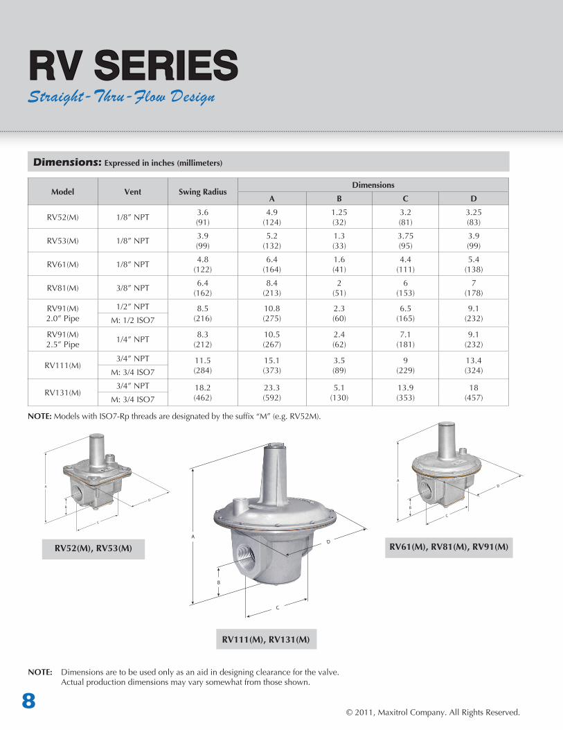
Dimensions: Expressed in inches (millimeters)
Model Vent Swing RadiusDimensions
A B C D
RV52(M) 1/8”NPT 3.6(91)
4.9(124)
1.25(32)
3.2(81)
3.25(83)
RV53(M) 1/8”NPT 3.9(99)
5.2(132)
1.3(33)
3.75(95)
3.9(99)
RV61(M) 1/8”NPT 4.8(122)
6.4(164)
1.6(41)
4.4(111)
5.4(138)
RV81(M) 3/8”NPT 6.4(162)
8.4(213)
2(51)
6(153)
7(178)
RV91(M)2.0” Pipe
1/2”NPT 8.5(216)
10.8(275)
2.3(60)
6.5(165)
9.1(232)M:1/2ISO7
RV91(M)2.5”Pipe 1/4”NPT 8.3
(212)10.5(267)
2.4(62)
7.1(181)
9.1(232)
RV111(M)3/4”NPT 11.5
(284)15.1(373)
3.5(89)
9(229)
13.4(324)M:3/4ISO7
RV131(M)3/4”NPT 18.2
(462)23.3(592)
5.1(130)
13.9(353)
18(457)M:3/4ISO7
NOTE: ModelswithISO7-Rpthreadsaredesignatedbythesuffix“M”(e.g.RV52M).
NOTE: Dimensionsaretobeusedonlyasanaidindesigningclearanceforthevalve. Actual production dimensions may vary somewhat from those shown.
A
B
A
B
A
B
RV61(M), RV81(M), RV91(M)
RV111(M), RV131(M)
RV52(M), RV53(M)
© 2011, Maxitrol Company. All Rights Reserved.9
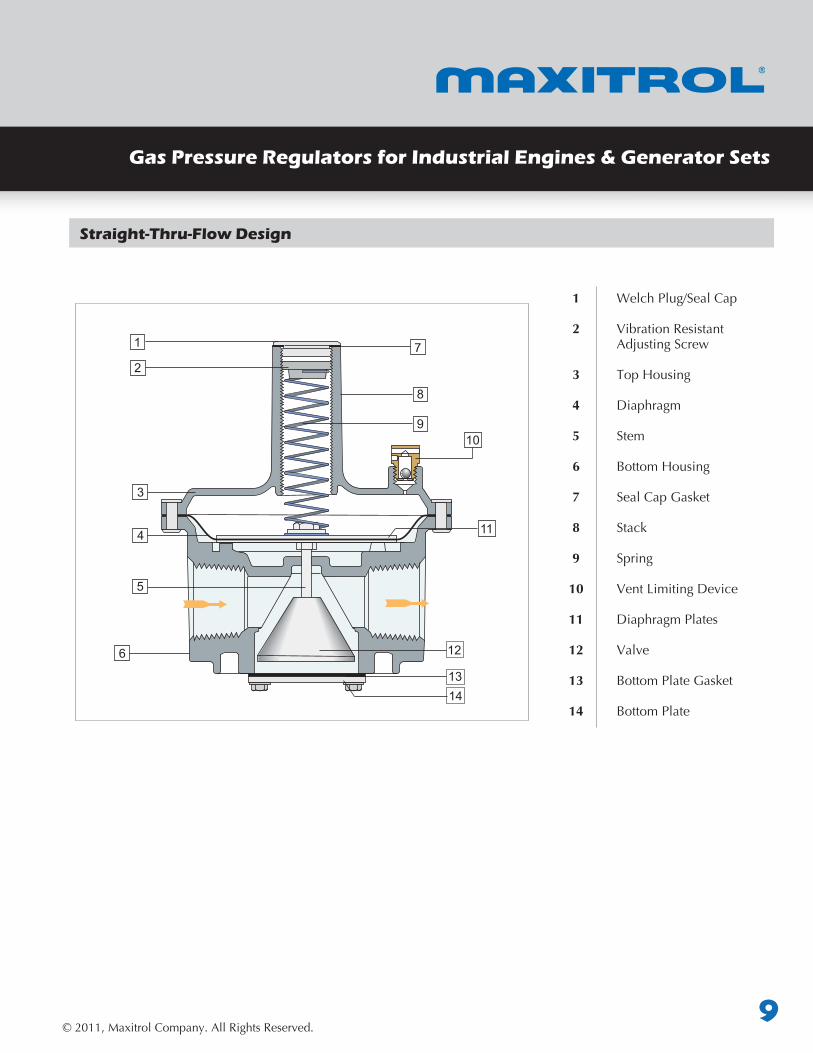
Straight-Thru-Flow Design
1 Welch Plug/Seal Cap
2 VibrationResistant Adjusting Screw
3 TopHousing
4 Diaphragm
5 Stem
6 BottomHousing
7 SealCapGasket
8 Stack
9 Spring
10 VentLimitingDevice
11 Diaphragm Plates
12 Valve
13 BottomPlateGasket
14 Bottom Plate
1
2
3
910
114
6
7
8
5
12
13
Gas Pressure Regulators for Industrial Engines & Generator Sets
14
© 2011, Maxitrol Company. All Rights Reserved.10
TT
R400(S)(Z)(M), R500(S)(Z)(M), R600(S)(Z)(M)
BALANCED VALVE REGULATOR
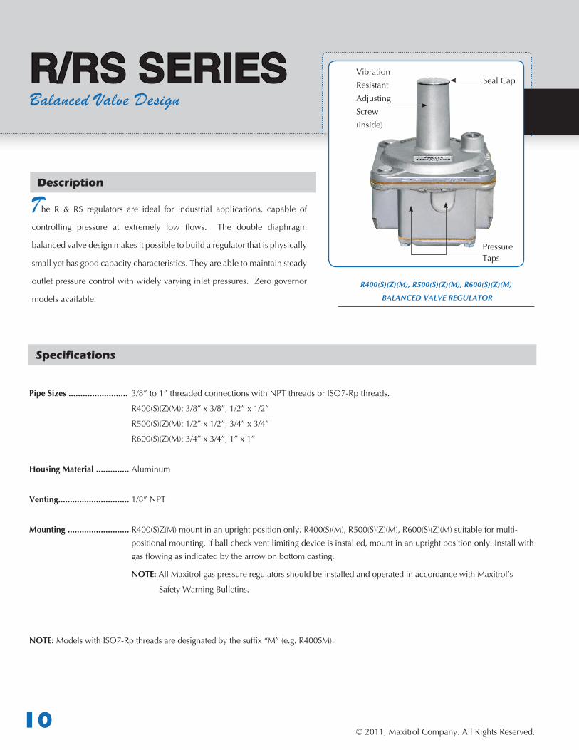
R/RS SERIESBalanced Valve Design
Specifications
Description
he R & RS regulators are ideal for industrial applications, capable of
controlling pressure at extremely low flows. The double diaphragm
balancedvalvedesignmakesitpossibletobuildaregulatorthatisphysically
smallyethasgoodcapacitycharacteristics.Theyareabletomaintainsteady
outletpressurecontrolwithwidelyvaryinginletpressures.Zerogovernor
modelsavailable.
Pipe Sizes ......................... 3/8”to1”threadedconnectionswithNPTthreadsorISO7-Rpthreads.
R400(S)(Z)(M):3/8”x3/8”,1/2”x1/2”
R500(S)(Z)(M):1/2”x1/2”,3/4”x3/4”
R600(S)(Z)(M):3/4”x3/4”,1”x1”
Housing Material .............. Aluminum
Venting..............................1/8”NPT
Mounting .......................... R400(S)Z(M)mountinanuprightpositiononly.R400(S)(M),R500(S)(Z)(M),R600(S)(Z)(M)suitableformulti- positionalmounting.Ifballcheckventlimitingdeviceisinstalled,mountinanuprightpositiononly.Installwith gasflowingasindicatedbythearrowonbottomcasting.
NOTE: AllMaxitrolgaspressureregulatorsshouldbeinstalledandoperatedinaccordancewithMaxitrol’s
Safety Warning Bulletins.
NOTE: ModelswithISO7-Rpthreadsaredesignatedbythesuffix“M”(e.g.R400SM).
VibrationResistant Adjusting Screw(inside)
Seal Cap
Pressure Taps
© 2011, Maxitrol Company. All Rights Reserved.11
Gas Pressure Regulators for Industrial Engines & Generator Sets
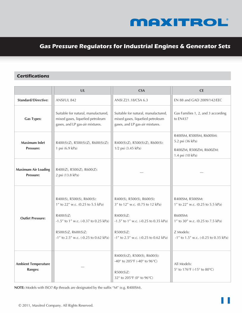
UL CSA CE
Standard/Directive: ANSI/UL842 ANSIZ21.18/CSA6.3 EN88andGAD2009/142/EEC
Gas Types:Suitablefornatural,manufactured,mixedgases,liquefiedpetroleumgases,andLPgas-airmixtures.
Suitablefornatural,manufactured,mixedgases,liquefiedpetroleumgases,andLPgas-airmixtures.
GasFamilies1,2,and3accordingtoEN437
Maximum Inlet Pressure:
R400(S)(Z),R500(S)(Z),R600(S)(Z):1psi(6.9kPa)
R400(S)(Z),R500(S)(Z),R600(S):1/2psi(3.45kPa)
R400SM,R500SM,R600SM:5.2psi(36kPa)
R400ZM,R500ZM,R600ZM:1.4psi(10kPa)
Maximum Air Loading Pressure:
R400(Z),R500(Z),R600(Z):2psi(13.8kPa)
--- ---
Outlet Pressure:
R400(S),R500(S),R600(S):1”to22”w.c.(0.25to5.5kPa)
R400(S)Z:-1.5”to1”w.c.(-0.37to0.25kPa)
R500(S)Z,R600(S)Z:-1”to2.5”w.c.(-0.25to0.62kPa)
R400(S),R500(S),R600(S):3”to12”w.c.(0.75to12kPa)
R400(S)Z:-1.5”to1”w.c.(-0.25to0.35kPa)
R500(S)Z:-1”to2.5”w.c.(-0.25to0.62kPa)
R400SM,R500SM:1”to22”w.c.(0.25to5.5kPa)
R600SM:1”to30”w.c.(0.25to7.5kPa)
ZModels:-1”to1.5”w.c.(-0.25to0.35kPa)
Ambient Temperature Ranges:
---
R400(S)(Z),R500(S),R600(S):-40°to205°F(-40°to96°C)
R500(S)Z:32°to205°F(0°to96°C)
AllModels:5°to176°F(-15°to80°C)
NOTE: ModelswithISO7-Rpthreadsaredesignatedbythesuffix“M”(e.g.R400SM).
Certifications
© 2011, Maxitrol Company. All Rights Reserved.12
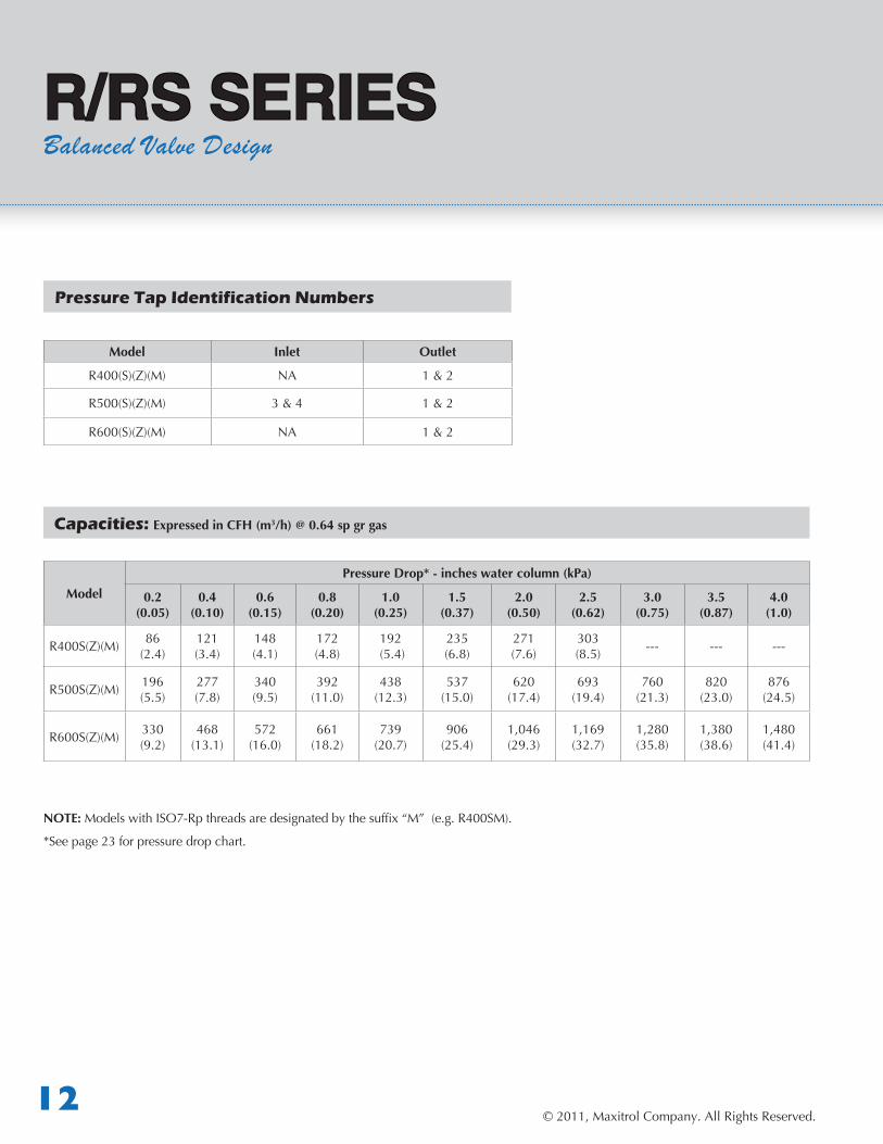
Model Inlet Outlet
R400(S)(Z)(M) NA 1 & 2
R500(S)(Z)(M) 3 & 4 1 & 2
R600(S)(Z)(M) NA 1 & 2
ModelPressure Drop* - inches water column (kPa)
0.2 (0.05)
0.4 (0.10)
0.6(0.15)
0.8(0.20)
1.0(0.25)
1.5(0.37)
2.0(0.50)
2.5(0.62)
3.0(0.75)
3.5(0.87)
4.0(1.0)
R400S(Z)(M) 86(2.4)
121 (3.4)
148 (4.1)
172 (4.8)
192(5.4)
235(6.8)
271 (7.6)
303 (8.5) --- --- ---
R500S(Z)(M) 196(5.5)
277 (7.8)
340 (9.5)
392 (11.0)
438 (12.3)
537(15.0)
620(17.4)
693(19.4)
760(21.3)
820 (23.0)
876(24.5)
R600S(Z)(M) 330 (9.2)
468(13.1)
572(16.0)
661(18.2)
739 (20.7)
906(25.4)
1,046(29.3)
1,169(32.7)
1,280 (35.8)
1,380 (38.6)
1,480 (41.4)
NOTE: ModelswithISO7-Rpthreadsaredesignatedbythesuffix“M”(e.g.R400SM).
*See page 23 for pressure drop chart.
Pressure Tap Identification Numbers
Capacities: Expressed in CFH (m3/h) @ 0.64 sp gr gas
R/RS SERIESBalanced Valve Design
© 2011, Maxitrol Company. All Rights Reserved.13
Gas Pressure Regulators for Industrial Engines & Generator Sets
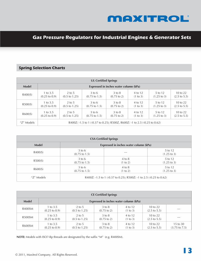
Spring Selection Charts
UL Certified Springs
Model Expressed in inches water column (kPa)
R400(S) 1to3.5(0.25to0.9)
2to5(0.5to1.25)
3to6(0.75to1.5)
3 to 8(0.75to2)
4 to 12(1to3)
5to12(1.25to3)
10 to 22(2.5to5.5)
R500(S) 1to3.5(0.25to0.9)
2to5(0.5to1.25)
3to6(0.75to1.5)
3 to 8(0.75to2)
4 to 12(1to3)
5to12(1.25to3)
10 to 22(2.5to5.5)
R600(S) 1to3.5(0.25to0.9)
2to5(0.5to1.25)
3to6(0.75to1.5)
3 to 8(0.75to2)
4 to 12(1to3)
5to12(1.25to3)
10 to 22(2.5to5.5)
“Z”Models R400Z:-1.5to1(-0.37to0.25);R500Z,R600Z:-1to2.5(-0.25to0.62)
CSA Certified Springs
Model Expressed in inches water column (kPa)
R400(S) 3to6(0.75to1.5) --- 5to12
(1.25to3)
R500(S) 3to6(0.75to1.5)
4 to 8(1to2)
5to12(1.25to3)
R600(S) 3to6(0.75to1.5)
4 to 8(1to2)
5to12(1.25to3)
“Z”Models R400Z:-1.5to1(-0.37to0.25);R500Z:-1to2.5(-0.25to0.62)
CE Certified Springs
Model Expressed in inches water column (kPa)
R400SM 1to3.5(0.25to0.9)
2to5(0.5to1.25)
3 to 8(0.75to2)
4 to 12(1to3)
10 to 22(2.5to5.5) ---
R500SM 1to3.5(0.25to0.9)
2to5(0.5to1.25)
3 to 8(0.75to2)
4 to 12(1to3)
10 to 22(2.5to5.5) ---
R600SM 1to3.5(0.25to0.9)
2to5(0.5to1.25)
3 to 8(0.75to2)
4 to 12(1to3)
10 to 22(2.5to5.5)
15to30(3.75to7.5)
NOTE: ModelswithISO7-Rpthreadsaredesignatedbythesuffix“M”(e.g.R400SM).
© 2011, Maxitrol Company. All Rights Reserved.14
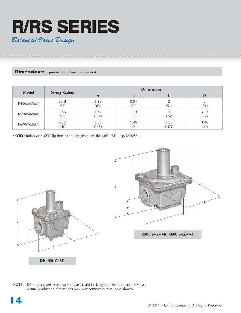
Dimensions: Expressed in inches (millimeters)
Model Swing RadiusDimensions
A B C D
R400(S)(Z)(M) 2.38 (60)
3.25(83)
0.94 (24)
2 (51)
2 (51)
R500(S)(Z)(M) 3.56(90)
4.69(119)
1.19 (30)
3 (76)
3.13 (79)
R600(S)(Z)(M) 4.32 (110)
5.68(145)
1.46(38)
4.03 (103)
3.88 (99)
NOTE: ModelswithISO7-Rpthreadsaredesignatedbythesuffix“M”(e.g.R400SM).
R/RS SERIESBalanced Valve Design
NOTE: Dimensionsaretobeusedonlyasanaidindesigningclearanceforthevalve. Actual production dimensions may vary somewhat from those shown.
A
B
A
BR500(S)(Z)(M), R600(S)(Z)(M)
R400(S)(Z)(M)
© 2011, Maxitrol Company. All Rights Reserved.15
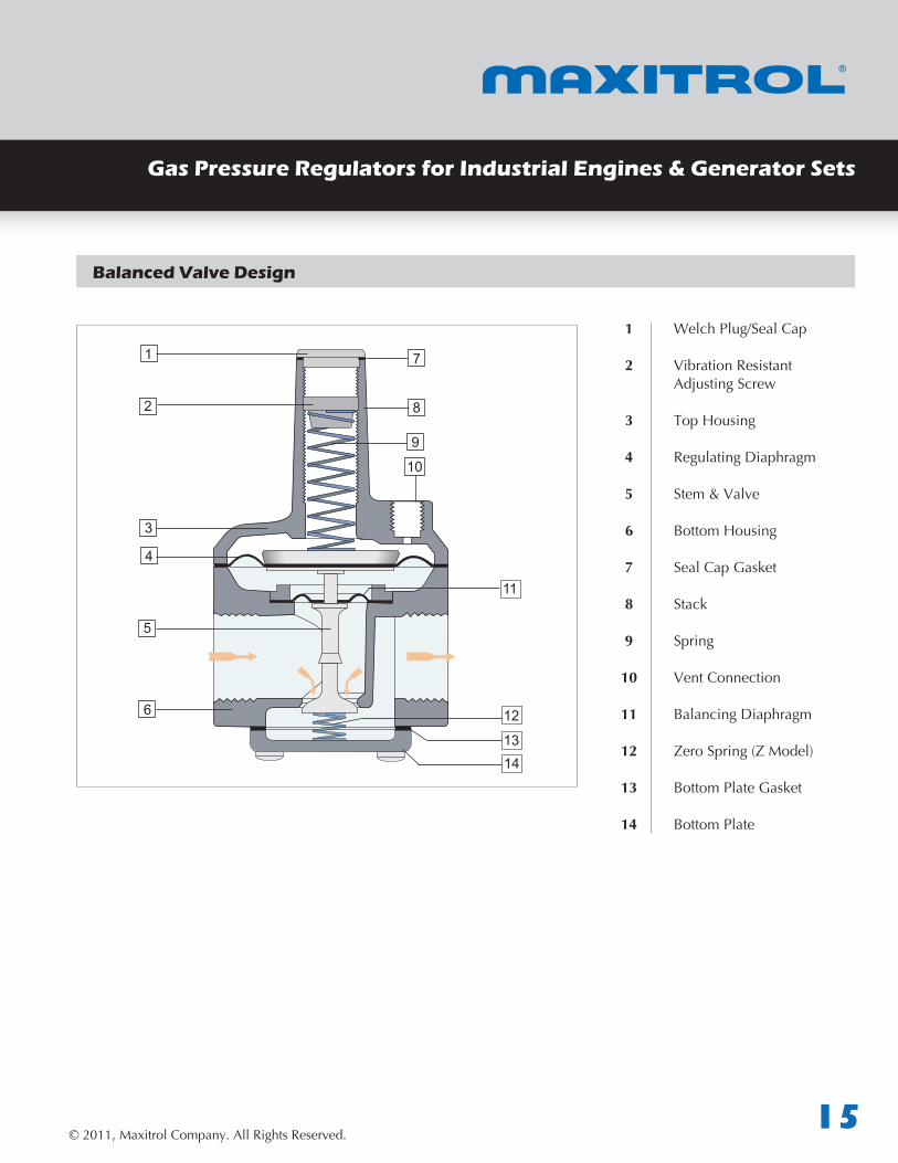
Balanced Valve Design
Gas Pressure Regulators for Industrial Engines & Generator Sets
1 Welch Plug/Seal Cap
2 VibrationResistant Adjusting Screw
3 TopHousing
4 Regulating Diaphragm
5 Stem & Valve
6 BottomHousing
7 SealCapGasket
8 Stack
9 Spring
10 Vent Connection
11 Balancing Diaphragm
12 ZeroSpring(ZModel)
13 BottomPlateGasket
14 Bottom Plate
1
2
3
9
10
4
6
7
8
5
11
13
12
14
© 2011, Maxitrol Company. All Rights Reserved.16
TT
210 SERIESBalanced Valve Design
Specifications
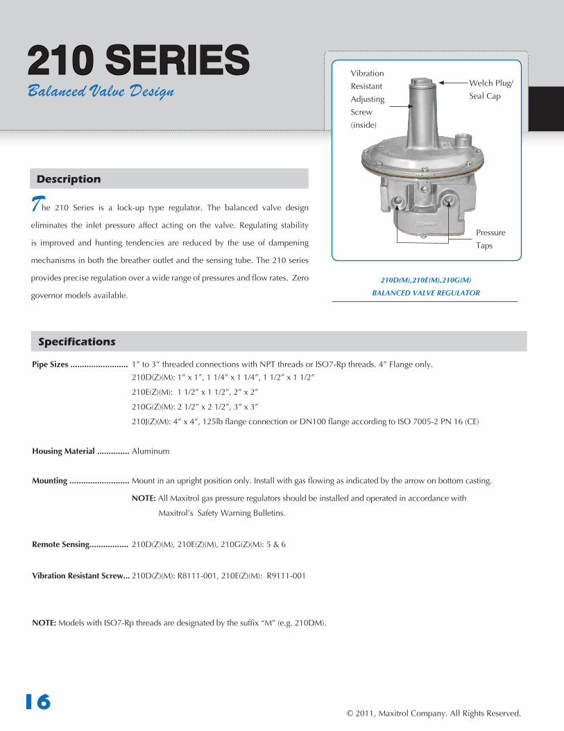
Description
he 210 Series is a lock-up type regulator. The balanced valve design
eliminates the inlet pressure affect acting on the valve. Regulating stability
is improved and hunting tendencies are reduced by the use of dampening
mechanismsinboththebreatheroutletandthesensingtube.The210series
providespreciseregulationoverawiderangeofpressuresandflowrates.Zero
governormodelsavailable.
Pipe Sizes ......................... 1” to 3”threadedconnectionswithNPTthreadsorISO7-Rpthreads.4”Flangeonly. 210D(Z)(M):1”x1”,11/4”x11/4”,11/2”x11/2”
210E(Z)(M):11/2”x11/2”,2”x2”
210G(Z)(M):21/2”x21/2”,3”x3”
210J(Z)(M):4”x4”,125lbflangeconnectionorDN100flangeaccordingtoISO7005-2PN16(CE)
Housing Material .............. Aluminum
Mounting .......................... Mountinanuprightpositiononly.Installwithgasflowingasindicatedbythearrowonbottomcasting.
NOTE: AllMaxitrolgaspressureregulatorsshouldbeinstalledandoperatedinaccordancewith
Maxitrol’s Safety Warning Bulletins.
Remote Sensing................. 210D(Z)(M),210E(Z)(M),210G(Z)(M):5&6
Vibration Resistant Screw... 210D(Z)(M):R8111-001,210E(Z)(M):R9111-001
NOTE: ModelswithISO7-Rpthreadsaredesignatedbythesuffix“M”(e.g.210DM).
210D(M),210E(M),210G(M)
BALANCED VALVE REGULATOR
VibrationResistant Adjusting Screw(inside)
Welch Plug/ Seal Cap
Pressure Taps
© 2011, Maxitrol Company. All Rights Reserved.17
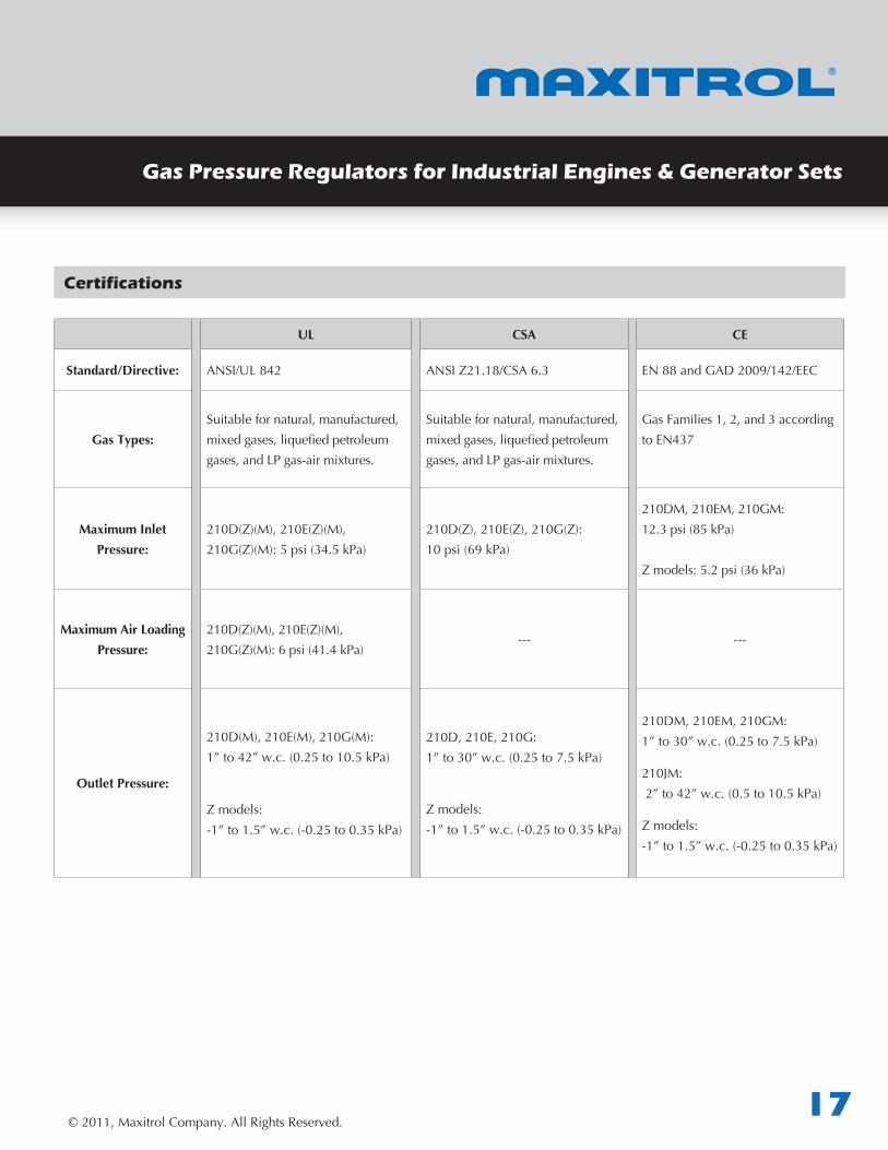
Gas Pressure Regulators for Industrial Engines & Generator Sets
UL CSA CE
Standard/Directive: ANSI/UL842 ANSIZ21.18/CSA6.3 EN88andGAD2009/142/EEC
Gas Types:Suitablefornatural,manufactured,mixedgases,liquefiedpetroleumgases,andLPgas-airmixtures.
Suitablefornatural,manufactured,mixedgases,liquefiedpetroleumgases,andLPgas-airmixtures.
GasFamilies1,2,and3accordingtoEN437
Maximum Inlet Pressure:
210D(Z)(M),210E(Z)(M),210G(Z)(M):5psi(34.5kPa)
210D(Z),210E(Z),210G(Z):10psi(69kPa)
210DM,210EM,210GM:12.3psi(85kPa)
Zmodels:5.2psi(36kPa)
Maximum Air Loading Pressure:
210D(Z)(M),210E(Z)(M),210G(Z)(M):6psi(41.4kPa)
--- ---
Outlet Pressure:
210D(M),210E(M),210G(M):1”to42”w.c.(0.25to10.5kPa)
Zmodels:-1”to1.5”w.c.(-0.25to0.35kPa)
210D,210E,210G:1”to30”w.c.(0.25to7.5kPa)
Zmodels:-1”to1.5”w.c.(-0.25to0.35kPa)
210DM,210EM,210GM:1”to30”w.c.(0.25to7.5kPa)
210JM:2”to42”w.c.(0.5to10.5kPa)
Zmodels:-1”to1.5”w.c.(-0.25to0.35kPa)
Certifications
© 2011, Maxitrol Company. All Rights Reserved.18
210 SERIESBalanced Valve Design
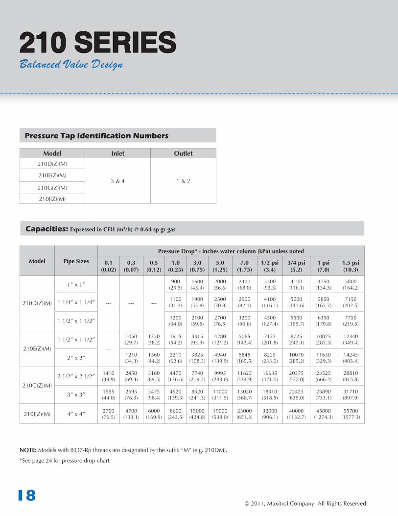
Model Inlet Outlet210D(Z)(M)
3 & 4 1 & 2210E(Z)(M)
210G(Z)(M)
210J(Z)(M)
Model Pipe Sizes
Pressure Drop* - inches water column (kPa) unless noted
0.1(0.02)
0.3(0.07)
0.5(0.12)
1.0(0.25)
3.0(0.75)
5.0(1.25)
7.0(1.75)
1/2 psi(3.4)
3/4 psi(5.2)
1 psi(7.0)
1.5 psi(10.3)
210D(Z)(M)
1” x 1”
--- --- ---
900(25.5)
1600(45.3)
2000(56.6)
2400(68.0)
3300(93.5)
4100(116.1)
4750(134.5)
5800(164.2)
1 1/4” x 1 1/4” 1100(31.2)
1900(53.8)
2500(70.8)
2900(82.1)
4100(116.1)
5000(141.6)
5850(165.7)
7150(202.5)
1 1/2” x 1 1/2” 1200(34.0)
2100(59.5)
2700(76.5)
3200(90.6)
4500(127.4)
5500(155.7)
6350(179.8)
7750(219.5)
210E(Z)(M)1 1/2” x 1 1/2”
---
1050(29.7)
1350(38.2)
1915(54.2)
3315(93.9)
4280(121.2)
5065(143.4)
7125(201.8)
8725(247.1)
10075(285.3)
12340(349.4)
2” x 2” 1210(34.3)
1560(44.2)
2210(62.6)
3825(108.3)
4940(139.9)
5845(165.5)
8225(233.0)
10070(285.2)
11630(329.3)
14245(403.4)
210G(Z)(M)2 1/2” x 2 1/2” 1410
(39.9)2450(69.4)
3160(89.5)
4470(126.6)
7740(219.2)
9995(283.0)
11825(334.9)
16635(471.0)
20375(577.0)
23525(666.2)
28810(815.8)
3” x 3” 1555(44.0)
2695(76.3)
3475(98.4)
4920(139.3)
8520(241.3)
11000(311.5)
13020(368.7)
18310(518.5)
22425(635.0)
25890(733.1)
31710(897.9)
210J(Z)(M) 4” x 4” 2700(76.5)
4700(133.1)
6000(169.9)
8600(243.5)
15000(424.8)
19000(538.0)
23000(651.3)
32000(906.1)
40000(1132.7)
45000(1274.3)
55700(1577.3)
NOTE: ModelswithISO7-Rpthreadsaredesignatedbythesuffix“M”(e.g.210DM).
*See page 24 for pressure drop chart.
Pressure Tap Identification Numbers
Capacities: Expressed in CFH (m3/h) @ 0.64 sp gr gas
© 2011, Maxitrol Company. All Rights Reserved.19
Gas Pressure Regulators for Industrial Engines & Generator Sets
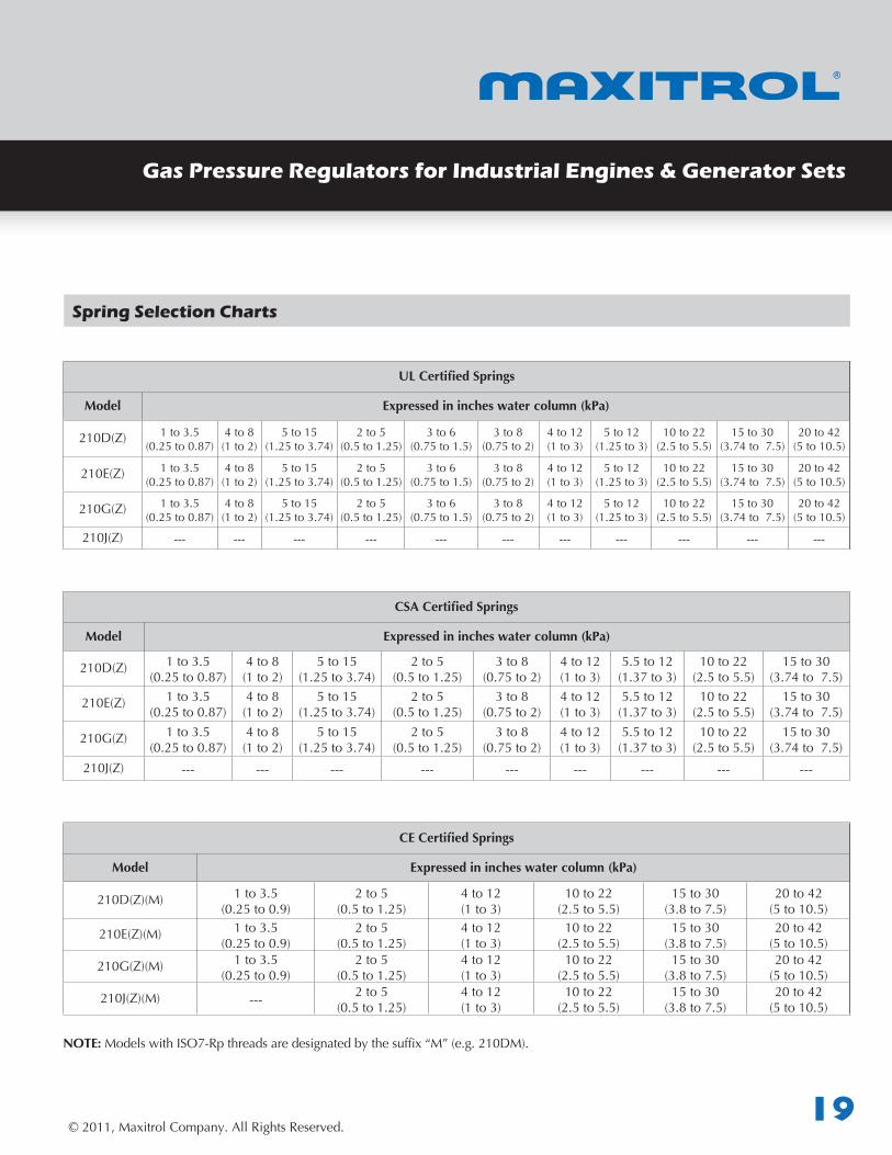
Spring Selection Charts
UL Certified Springs
Model Expressed in inches water column (kPa)
210D(Z) 1to3.5(0.25to0.87)
4 to 8(1to2)
5to15(1.25to3.74)
2to5(0.5to1.25)
3to6(0.75to1.5)
3 to 8(0.75to2)
4 to 12(1to3)
5to12(1.25to3)
10 to 22(2.5to5.5)
15to30(3.74to7.5)
20 to 42(5to10.5)
210E(Z) 1to3.5(0.25to0.87)
4 to 8(1to2)
5to15(1.25to3.74)
2to5(0.5to1.25)
3to6(0.75to1.5)
3 to 8(0.75to2)
4 to 12(1to3)
5to12(1.25to3)
10 to 22(2.5to5.5)
15to30(3.74to7.5)
20 to 42(5to10.5)
210G(Z) 1to3.5(0.25to0.87)
4 to 8(1to2)
5to15(1.25to3.74)
2to5(0.5to1.25)
3to6(0.75to1.5)
3 to 8(0.75to2)
4 to 12(1to3)
5to12(1.25to3)
10 to 22(2.5to5.5)
15to30(3.74to7.5)
20 to 42(5to10.5)
210J(Z) --- --- --- --- --- --- --- --- --- --- ---
CSA Certified Springs
Model Expressed in inches water column (kPa)
210D(Z) 1to3.5(0.25to0.87)
4 to 8(1to2)
5to15(1.25to3.74)
2to5(0.5to1.25)
3 to 8(0.75to2)
4 to 12(1to3)
5.5to12(1.37to3)
10 to 22(2.5to5.5)
15to30(3.74to7.5)
210E(Z) 1to3.5(0.25to0.87)
4 to 8(1to2)
5to15(1.25to3.74)
2to5(0.5to1.25)
3 to 8(0.75to2)
4 to 12(1to3)
5.5to12(1.37to3)
10 to 22(2.5to5.5)
15to30(3.74to7.5)
210G(Z) 1to3.5(0.25to0.87)
4 to 8(1to2)
5to15(1.25to3.74)
2to5(0.5to1.25)
3 to 8(0.75to2)
4 to 12(1to3)
5.5to12(1.37to3)
10 to 22(2.5to5.5)
15to30(3.74to7.5)
210J(Z) --- --- --- --- --- --- --- --- ---
CE Certified Springs
Model Expressed in inches water column (kPa)
210D(Z)(M) 1to3.5(0.25to0.9)
2to5(0.5to1.25)
4 to 12(1to3)
10 to 22(2.5to5.5)
15to30(3.8to7.5)
20 to 42(5to10.5)
210E(Z)(M) 1to3.5(0.25to0.9)
2to5(0.5to1.25)
4 to 12(1to3)
10 to 22(2.5to5.5)
15to30(3.8to7.5)
20 to 42(5to10.5)
210G(Z)(M) 1to3.5(0.25to0.9)
2to5(0.5to1.25)
4 to 12(1to3)
10 to 22(2.5to5.5)
15to30(3.8to7.5)
20 to 42(5to10.5)
210J(Z)(M) --- 2to5(0.5to1.25)
4 to 12(1to3)
10 to 22(2.5to5.5)
15to30(3.8to7.5)
20 to 42(5to10.5)
NOTE: ModelswithISO7-Rpthreadsaredesignatedbythesuffix“M”(e.g.210DM).
© 2011, Maxitrol Company. All Rights Reserved.20
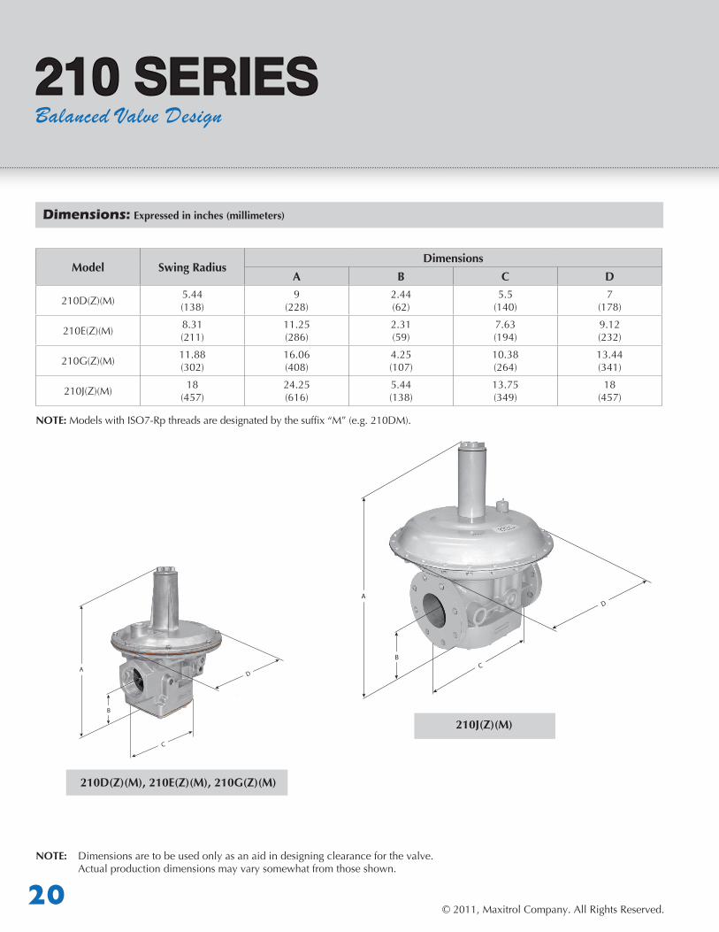
Dimensions: Expressed in inches (millimeters)
Model Swing RadiusDimensions
A B C D
210D(Z)(M) 5.44(138)
9(228)
2.44(62)
5.5(140)
7(178)
210E(Z)(M) 8.31(211)
11.25(286)
2.31(59)
7.63(194)
9.12(232)
210G(Z)(M) 11.88(302)
16.06(408)
4.25(107)
10.38(264)
13.44(341)
210J(Z)(M) 18(457)
24.25(616)
5.44(138)
13.75(349)
18(457)
A
B
210 SERIESBalanced Valve Design
NOTE: Dimensionsaretobeusedonlyasanaidindesigningclearanceforthevalve. Actual production dimensions may vary somewhat from those shown.
A
B
210J(Z)(M)
210D(Z)(M), 210E(Z)(M), 210G(Z)(M)
NOTE: ModelswithISO7-Rpthreadsaredesignatedbythesuffix“M”(e.g.210DM).
© 2011, Maxitrol Company. All Rights Reserved.21
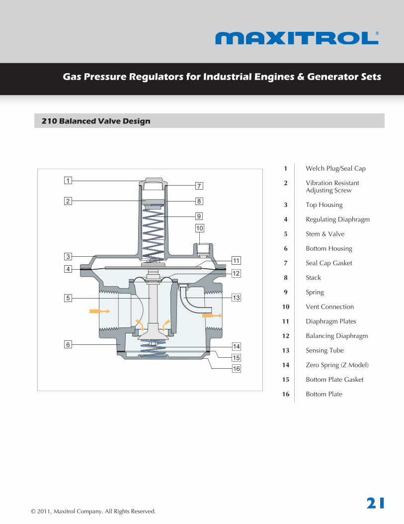
210 Balanced Valve Design
Gas Pressure Regulators for Industrial Engines & Generator Sets
1 Welch Plug/Seal Cap
2 VibrationResistant Adjusting Screw
3 TopHousing
4 Regulating Diaphragm
5 Stem & Valve
6 BottomHousing
7 SealCapGasket
8 Stack
9 Spring
10 Vent Connection
11 Diaphragm Plates
12 Balancing Diaphragm
13 SensingTube
14 ZeroSpring(ZModel)
15 BottomPlateGasket
16 Bottom Plate
1
2
3
9
10
114
7
8
5
12
13
15
6 14
16
© 2011, Maxitrol Company. All Rights Reserved.22
PRESSURE DROP CHARTS
2 4 8 40 50 60 80 100 200 300 800 10006 10 20 30 400 600
10
5
4
32,5
0,5
0,4
0,30,25
0,2
0,15
0,1
0,05
2
1,5
1
2,5 5,0 9,9 49,6 62 74,4 99,2 124 248 372 990 12407,4 12,4 24,8 27,2 496 744
1,6 3,2 6,4 32 40 48 64 80 160 240 640 8004,8 8 16 24 320 480
RV6
1(M
)
RV52
(M)
RV11
1(M)
RV11
1(M
)
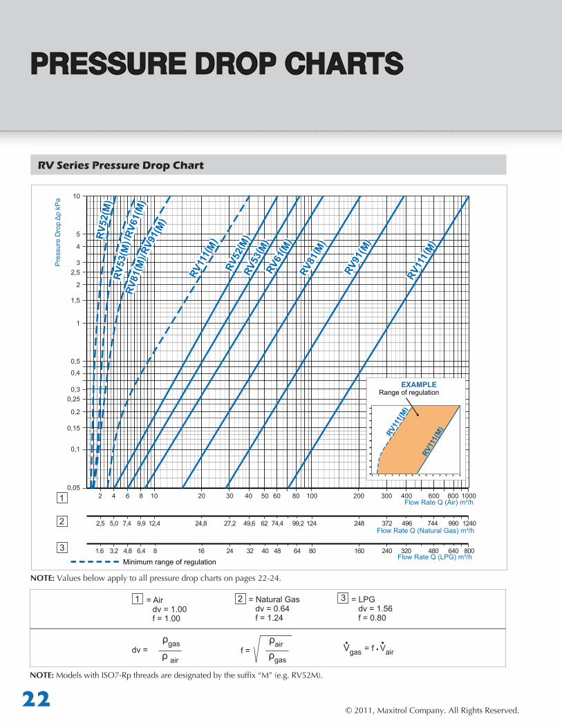
RV Series Pressure Drop Chart
= Air dv = 1.00 f = 1.00
= Natural Gas dv = 0.64 f = 1.24
= LPG dv = 1.56 f = 0.80
dv = ρgas
ρ airVgas = f Vair• •
•
3
f = ρairρgas
NOTE:Valuesbelowapplytoallpressuredropchartsonpages22-24.
1 2
1
2
3
Range of regulationEXAMPLE
Pre
ssur
e D
rop
Δp
kPa
Flow Rate Q (Air) m³/h
Flow Rate Q (Natural Gas) m³/h
Flow Rate Q (LPG) m³/hMinimum range of regulation
NOTE: ModelswithISO7-Rpthreadsaredesignatedbythesuffix“M”(e.g.RV52M).

© 2011, Maxitrol Company. All Rights Reserved.23
PRESSURE DROP CHARTSGas Pressure Regulators for Industrial Engines & Generator Sets
25
20
15
10
5
2,5
2
1,5
1
0,5
0,4
0,3
4
3
0,251 104 6 20 30 40 60 80 1002 3 8
1,2 12,45,5 7,4 24,8 37,2 49,6 74,4 92,2 1242,5 3,7 9,9
0,8 8,03,2 4,8 16 24 32 48 64 801,6 2,4 6,4
R600
S(Z)
(M)
R600
R500
R400
S(Z)
(M)
R600
S(Z)
(M)
R500
S(Z)
(M)
R/RS Series Pressure Drop Chart
1
2
3
Range of regulationEXAMPLE
Pre
ssur
e D
rop
Δp
kPa
Flow Rate Q (Air) m³/h
Flow Rate Q (Natural Gas) m³/h
Flow Rate Q (LPG) m³/h
NOTE: ModelswithISO7-Rpthreadsaredesignatedbythesuffix“M”(e.g.R400SM).
© 2011, Maxitrol Company. All Rights Reserved.24
50
40
30
20
15
10
5
4
3
2,5
2
1,5
1
0,5
0,4
0,3
0,258 9 10 20 30 40 50 60 80 100 200 300 400 500 600 800 1000
9,9 11,2 14,4 24,8 27,2 49,6 62 74,4 99,2 124 248 372 496 620 744 922 1240
6,4 7,2 8 16 24 32 40 48 64 80 160 240 320 400 480 640 800
210D
(M)
210D
M21
0D(M
)
210E
(M)
210G
(M)
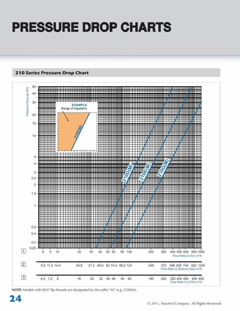
PRESSURE DROP CHARTS
210 Series Pressure Drop Chart
1
2
3
Range of regulationEXAMPLE
Pre
ssur
e D
rop
Δp
kPa
Flow Rate Q (Air) m³/h
Flow Rate Q (Natural Gas) m³/h
Flow Rate Q (LPG) m³/h
NOTE: ModelswithISO7-Rpthreadsaredesignatedbythesuffix“M”(e.g.210DM).
© 2011, Maxitrol Company. All Rights Reserved.25
PRESSURE DROP CHARTSGas Pressure Regulators for Industrial Engines & Generator Sets
Notes:
© 2011, Maxitrol Company. All Rights Reserved.26
© 2011, Maxitrol Company. All Rights Reserved.27
Gas Pressure Regulators for Industrial Engines & Generator Sets
Exclusive Distributor North Americafor Mertik Maxitrol
Maxitrol Company, Inc.23555 Telegraph Rd., PO Box 2230Southfield, MI 48037-2230USATel: +1 248-356-1400Fax: +1 248-356-0829www.maxitrol.com
GPR_GEN_MS_EN_02.2011
© 2011 Maxitrol Company, All Rights Reserved.
Exclusive Distributor Europefor Maxitrol Company
Mertik Maxitrol GmbH & Co. KGWarnstedter Str. 3
06502 ThaleGermany
Tel: + 49 3947 400-0Fax: + 49 3947 400-200www.mertikmaxitrol.com