Embed Size (px)
Citation preview
GDIS2017
Gas Metal Arc Welding of Advanced High-
Strength Steels
Min Kuo, PhD
ArcelorMittal
#GDIS | #SteelMatters 3
A/SP Team Members
• Min Kuo, ArcelorMittal
• Tom Natale, AK Steel Corporation
• Stephen Tate, AK Steel
Corporation
• Hassan Ghassemi, ArcelorMittal
• Elliot Biro, ArcelorMittal
• Amanda Scherzer,
FiatChryslerAmerica US LLC
• Doug Howe, Ford Motor Company
• Mike Palko, Ford Motor Company
• Richard Carlson, General Motors
• Weiping Sun, Nucor Corporation
• Chonghua (Cindy) Jiang, AET Integration
Inc.
• Justin Hunt, AET Integration Inc.
• Donald F. Maatz, Jr. R&E Engineering
Services
• Daniel L. Galiher, Tower International
• Vaidyanath B. Rajan, Lincoln Electric
• Richard Paul, Auto/Steel Partnership
#GDIS | #SteelMatters 4
Study Objective
• The objective of this project is to evaluate
the effects of gas metal arc welding (GMAW)
and gas metal arc brazing (GMAB) on AHSS
and UHSS and to identify the impact of
welding on joint strength and
microhardness.
#GDIS | #SteelMatters 5
Test Methods
• Tests include X-ray inspection, micro
hardness, quasi-static shear tension, and
metallurgical cross-sections. Selected thin
gauge steels were joined using both GMAW
and GMAB.
#GDIS | #SteelMatters 6
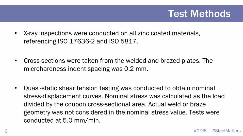
Test Methods
• X-ray inspections were conducted on all zinc coated materials,
referencing ISO 17636-2 and ISO 5817.
• Cross-sections were taken from the welded and brazed plates. The
microhardness indent spacing was 0.2 mm.
• Quasi-static shear tension testing was conducted to obtain nominal
stress-displacement curves. Nominal stress was calculated as the load
divided by the coupon cross-sectional area. Actual weld or braze
geometry was not considered in the nominal stress value. Tests were
conducted at 5.0 mm/min.
#GDIS | #SteelMatters 7
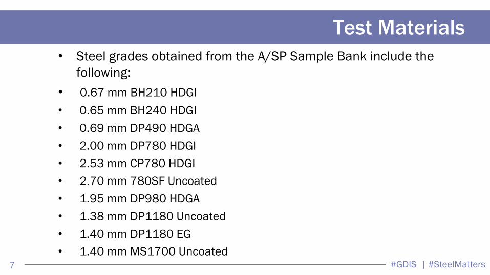
Test Materials
• Steel grades obtained from the A/SP Sample Bank include the
following:
• 0.67 mm BH210 HDGI
• 0.65 mm BH240 HDGI
• 0.69 mm DP490 HDGA
• 2.00 mm DP780 HDGI
• 2.53 mm CP780 HDGI
• 2.70 mm 780SF Uncoated
• 1.95 mm DP980 HDGA
• 1.38 mm DP1180 Uncoated
• 1.40 mm DP1180 EG
• 1.40 mm MS1700 Uncoated
#GDIS | #SteelMatters 8
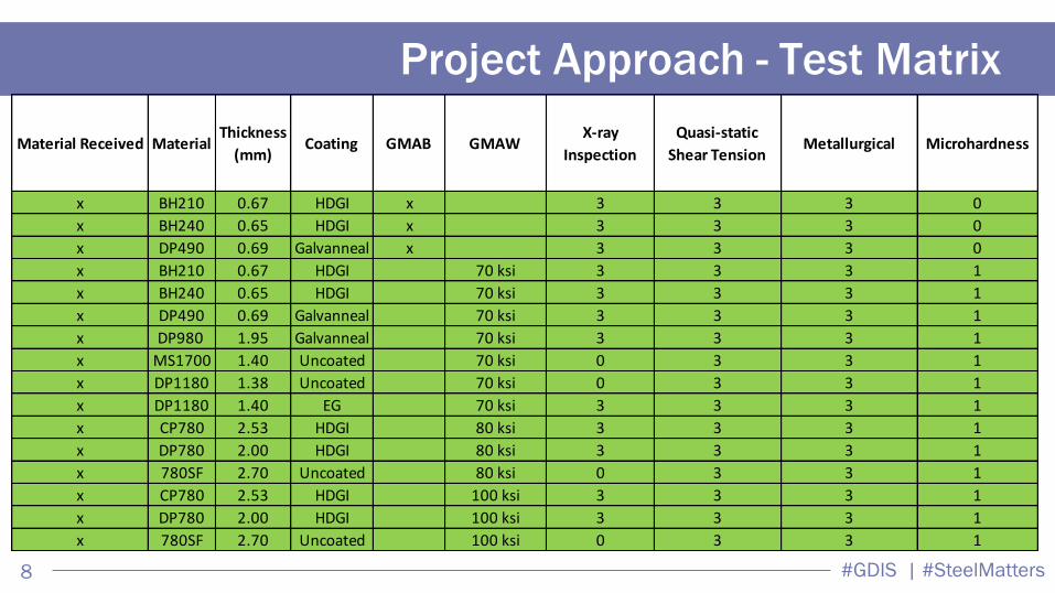
Project Approach - Test Matrix
Material Received MaterialThickness
(mm)Coating GMAB GMAW
X-ray
Inspection
Quasi-static
Shear TensionMetallurgical Microhardness
x BH210 0.67 HDGI x 3 3 3 0
x BH240 0.65 HDGI x 3 3 3 0
x DP490 0.69 Galvanneal x 3 3 3 0
x BH210 0.67 HDGI 70 ksi 3 3 3 1
x BH240 0.65 HDGI 70 ksi 3 3 3 1
x DP490 0.69 Galvanneal 70 ksi 3 3 3 1
x DP980 1.95 Galvanneal 70 ksi 3 3 3 1
x MS1700 1.40 Uncoated 70 ksi 0 3 3 1
x DP1180 1.38 Uncoated 70 ksi 0 3 3 1
x DP1180 1.40 EG 70 ksi 3 3 3 1
x CP780 2.53 HDGI 80 ksi 3 3 3 1
x DP780 2.00 HDGI 80 ksi 3 3 3 1
x 780SF 2.70 Uncoated 80 ksi 0 3 3 1
x CP780 2.53 HDGI 100 ksi 3 3 3 1
x DP780 2.00 HDGI 100 ksi 3 3 3 1
x 780SF 2.70 Uncoated 100 ksi 0 3 3 1
#GDIS | #SteelMatters 9
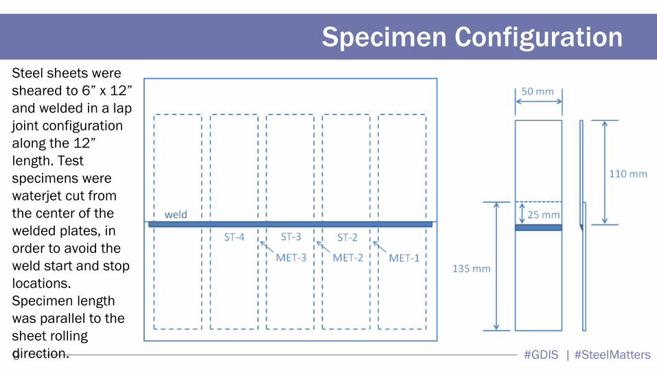
Specimen Configuration Steel sheets were
sheared to 6” x 12”
and welded in a lap
joint configuration
along the 12”
length. Test
specimens were
waterjet cut from
the center of the
welded plates, in
order to avoid the
weld start and stop
locations.
Specimen length
was parallel to the
sheet rolling
direction.
#GDIS | #SteelMatters 10
Welding Position and Set-up
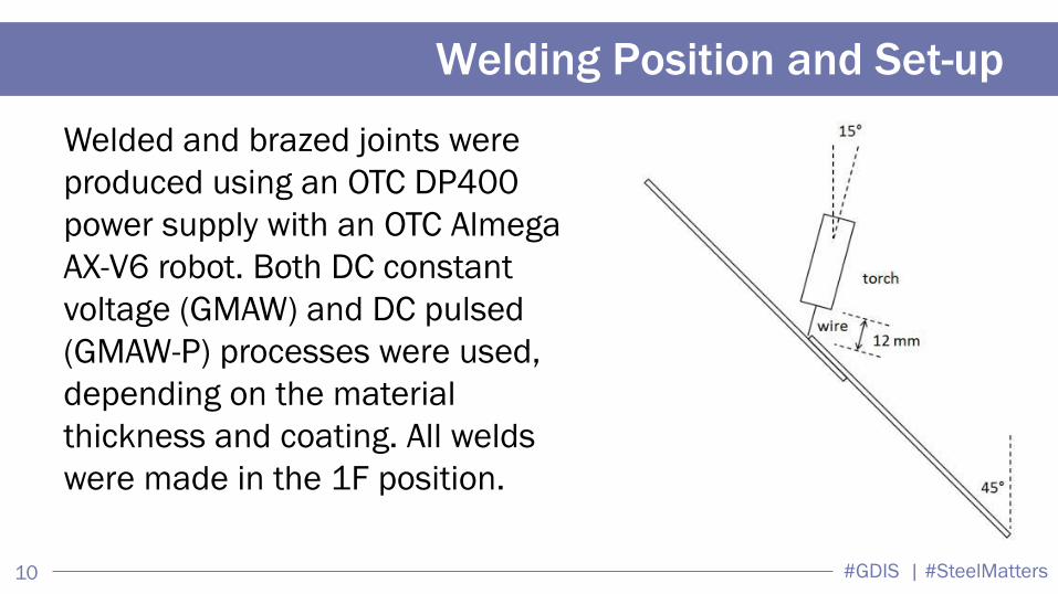
Welded and brazed joints were
produced using an OTC DP400
power supply with an OTC Almega
AX-V6 robot. Both DC constant
voltage (GMAW) and DC pulsed
(GMAW-P) processes were used,
depending on the material
thickness and coating. All welds
were made in the 1F position.
#GDIS | #SteelMatters 11
Weld Fillers
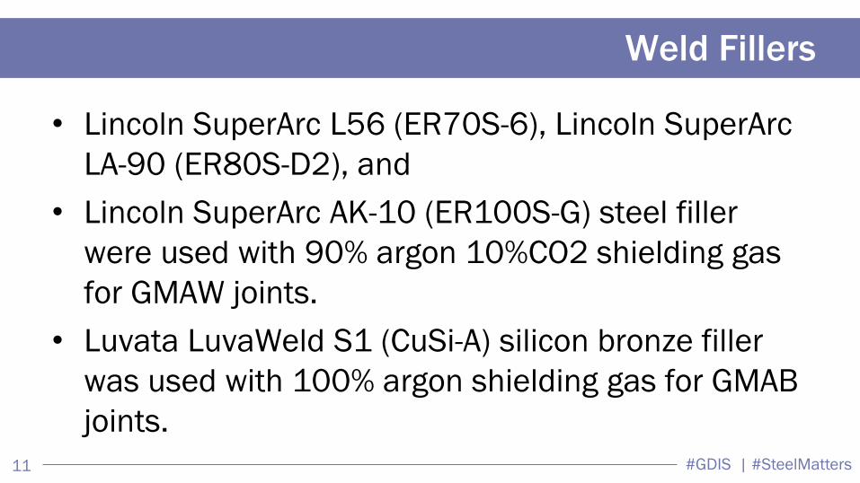
• Lincoln SuperArc L56 (ER70S-6), Lincoln SuperArc
LA-90 (ER80S-D2), and
• Lincoln SuperArc AK-10 (ER100S-G) steel filler
were used with 90% argon 10%CO2 shielding gas
for GMAW joints.
• Luvata LuvaWeld S1 (CuSi-A) silicon bronze filler
was used with 100% argon shielding gas for GMAB
joints.
#GDIS | #SteelMatters 12
Welding Parameter
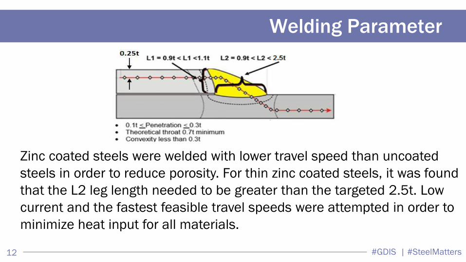
Zinc coated steels were welded with lower travel speed than uncoated
steels in order to reduce porosity. For thin zinc coated steels, it was found
that the L2 leg length needed to be greater than the targeted 2.5t. Low
current and the fastest feasible travel speeds were attempted in order to
minimize heat input for all materials.
#GDIS | #SteelMatters 13
Welding Parameter Summary
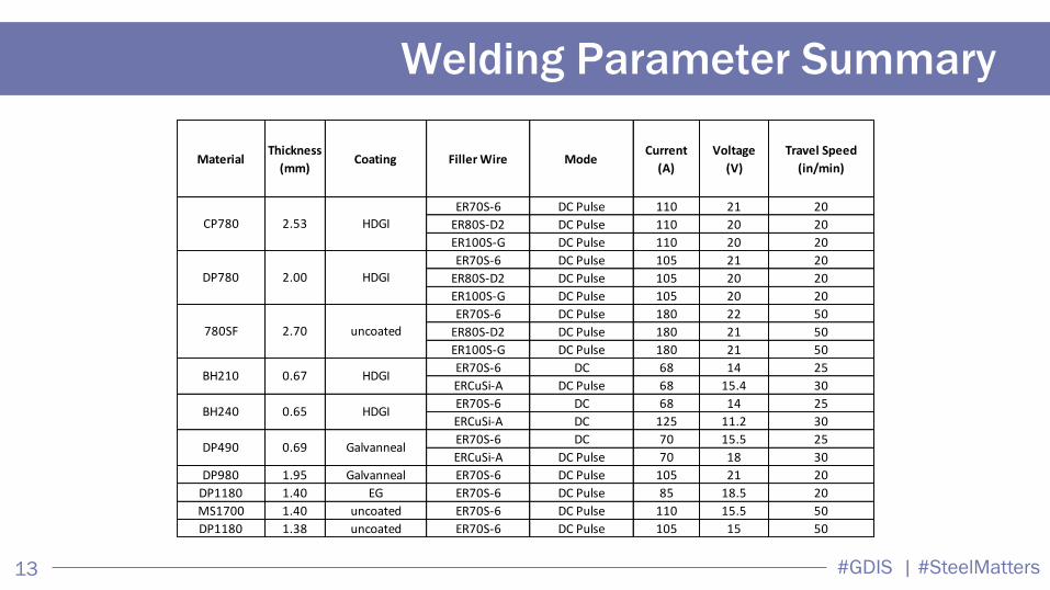
MaterialThickness
(mm)Coating Filler Wire Mode
Current
(A)
Voltage
(V)
Travel Speed
(in/min)
ER70S-6 DC Pulse 110 21 20
ER80S-D2 DC Pulse 110 20 20
ER100S-G DC Pulse 110 20 20
ER70S-6 DC Pulse 105 21 20
ER80S-D2 DC Pulse 105 20 20
ER100S-G DC Pulse 105 20 20
ER70S-6 DC Pulse 180 22 50
ER80S-D2 DC Pulse 180 21 50
ER100S-G DC Pulse 180 21 50
ER70S-6 DC 68 14 25
ERCuSi-A DC Pulse 68 15.4 30
ER70S-6 DC 68 14 25
ERCuSi-A DC 125 11.2 30
ER70S-6 DC 70 15.5 25
ERCuSi-A DC Pulse 70 18 30
DP980 1.95 Galvanneal ER70S-6 DC Pulse 105 21 20
DP1180 1.40 EG ER70S-6 DC Pulse 85 18.5 20
MS1700 1.40 uncoated ER70S-6 DC Pulse 110 15.5 50
DP1180 1.38 uncoated ER70S-6 DC Pulse 105 15 50
780SF
BH210 HDGI0.67
uncoated2.70
CP780
DP780 HDGI2.00
HDGI2.53
BH240 0.65 HDGI
DP490 0.69 Galvanneal
#GDIS | #SteelMatters 14
Test Results
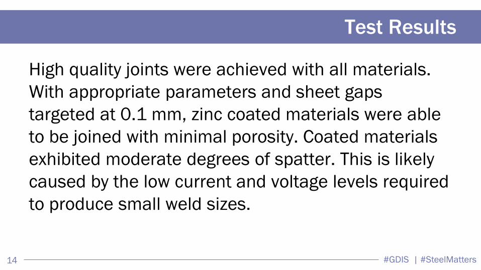
High quality joints were achieved with all materials.
With appropriate parameters and sheet gaps
targeted at 0.1 mm, zinc coated materials were able
to be joined with minimal porosity. Coated materials
exhibited moderate degrees of spatter. This is likely
caused by the low current and voltage levels required
to produce small weld sizes.
#GDIS | #SteelMatters 15
X-ray Results
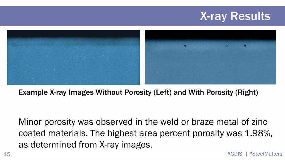
Example X-ray Images Without Porosity (Left) and With Porosity (Right)
Minor porosity was observed in the weld or braze metal of zinc
coated materials. The highest area percent porosity was 1.98%,
as determined from X-ray images.
#GDIS | #SteelMatters 16
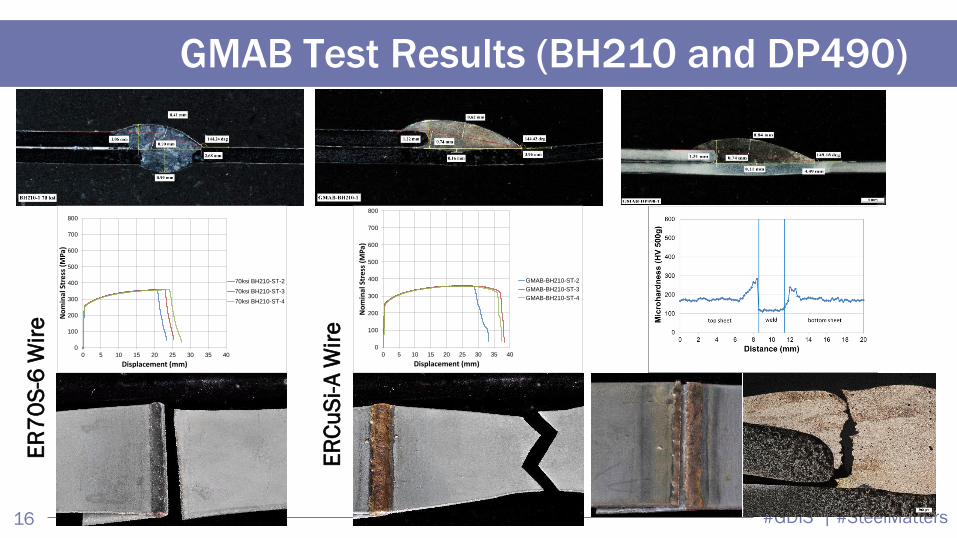
GMAB Test Results (BH210 and DP490)
0
100
200
300
400
500
600
700
800
0 5 10 15 20 25 30 35 40
No
min
al S
tre
ss (
MP
a)
Displacement (mm)
70ksi BH210-ST-2
70ksi BH210-ST-3
70ksi BH210-ST-4
0
100
200
300
400
500
600
700
800
0 5 10 15 20 25 30 35 40
No
min
al S
tre
ss (
MP
a)
Displacement (mm)
GMAB-BH210-ST-2
GMAB-BH210-ST-3
GMAB-BH210-ST-4
ER
70
S-6
Wir
e
ER
Cu
Si-
A W
ire
#GDIS | #SteelMatters 17
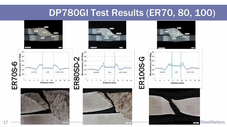
DP780GI Test Results (ER70, 80, 100) E
R7
0S
-6
ER
80
SD
-2
ER
10
0S
-G
#GDIS | #SteelMatters 18
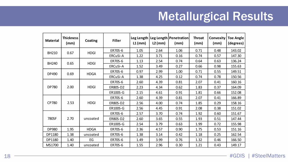
Metallurgical Results
MaterialThickness
(mm)Coating Filler
Leg Length
L1 (mm)
Leg Length
L2 (mm)
Penetration
(mm)
Throat
(mm)
Convexity
(mm)
Toe Angle
(degrees)
ER70S-6 1.05 2.64 1.06 0.71 0.48 143.02
ERCuSi-A 1.22 3.71 0.16 0.74 0.57 147.30
ER70S-6 1.13 2.54 0.74 0.64 0.63 136.24
ERCuSi-A 1.52 3.49 0.27 0.66 0.98 155.63
ER70S-6 0.97 2.99 1.00 0.71 0.55 149.51
ERCuSi-A 1.38 4.25 0.12 0.74 0.78 150.56
ER70S-6 2.60 4.39 0.81 2.07 0.41 160.16
ER80S-D2 2.23 4.34 0.62 1.83 0.37 164.09
ER100S-G 2.15 4.61 0.91 1.81 0.66 152.08
ER70S-6 2.60 4.39 0.81 2.07 0.41 166.89
ER80S-D2 2.56 4.00 0.74 1.85 0.29 158.16
ER100S-G 2.56 4.45 0.91 2.08 0.38 151.02
ER70S-6 2.57 3.70 0.74 1.92 0.60 151.67
ER80S-D2 2.60 3.65 0.55 1.93 0.51 147.44
ER100S-G 2.54 3.79 0.63 1.99 0.72 155.98
DP980 1.95 HDGA ER70S-6 2.36 4.57 0.90 1.75 0.53 151.16
DP1180 1.38 uncoated ER70S-6 1.38 3.14 0.42 1.18 0.25 162.54
DP1180 1.40 EG ER70S-6 1.49 3.99 0.76 1.32 0.46 166.50
MS1700 1.40 uncoated ER70S-6 1.55 2.96 0.30 1.21 0.43 149.17
780SF 2.70 uncoated
DP490 HDGA0.69
0.65 HDGIBH240
CP780 2.53 HDGI
BH210 0.67 HDGI
DP780 2.00 HDGI
#GDIS | #SteelMatters 19
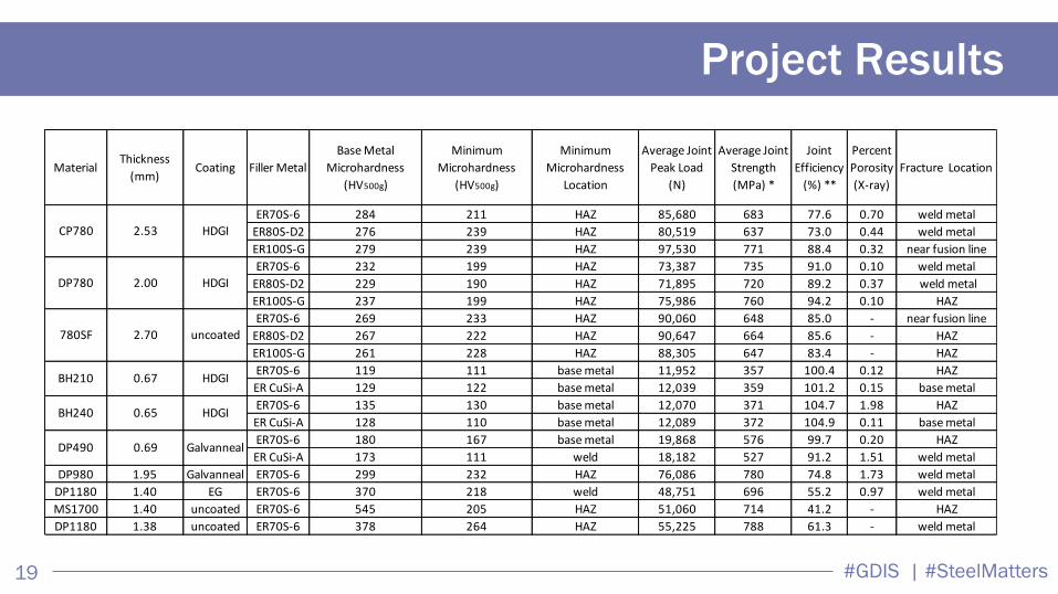
Project Results
MaterialThickness
(mm)Coating Filler Metal
Base Metal
Microhardness
(HV500g)
Minimum
Microhardness
(HV500g)
Minimum
Microhardness
Location
Average Joint
Peak Load
(N)
Average Joint
Strength
(MPa) *
Joint
Efficiency
(%) **
Percent
Porosity
(X-ray)
Fracture Location
ER70S-6 284 211 HAZ 85,680 683 77.6 0.70 weld metal
ER80S-D2 276 239 HAZ 80,519 637 73.0 0.44 weld metal
ER100S-G 279 239 HAZ 97,530 771 88.4 0.32 near fusion line
ER70S-6 232 199 HAZ 73,387 735 91.0 0.10 weld metal
ER80S-D2 229 190 HAZ 71,895 720 89.2 0.37 weld metal
ER100S-G 237 199 HAZ 75,986 760 94.2 0.10 HAZ
ER70S-6 269 233 HAZ 90,060 648 85.0 - near fusion line
ER80S-D2 267 222 HAZ 90,647 664 85.6 - HAZ
ER100S-G 261 228 HAZ 88,305 647 83.4 - HAZ
ER70S-6 119 111 base metal 11,952 357 100.4 0.12 HAZ
ER CuSi-A 129 122 base metal 12,039 359 101.2 0.15 base metal
ER70S-6 135 130 base metal 12,070 371 104.7 1.98 HAZ
ER CuSi-A 128 110 base metal 12,089 372 104.9 0.11 base metal
ER70S-6 180 167 base metal 19,868 576 99.7 0.20 HAZ
ER CuSi-A 173 111 weld 18,182 527 91.2 1.51 weld metal
DP980 1.95 Galvanneal ER70S-6 299 232 HAZ 76,086 780 74.8 1.73 weld metal
DP1180 1.40 EG ER70S-6 370 218 weld 48,751 696 55.2 0.97 weld metal
MS1700 1.40 uncoated ER70S-6 545 205 HAZ 51,060 714 41.2 - HAZ
DP1180 1.38 uncoated ER70S-6 378 264 HAZ 55,225 788 61.3 - weld metal
BH210 0.67 HDGI
uncoated
HDGI
HDGICP780
DP780
780SF 2.70
2.00
2.53
BH240 0.65 HDGI
DP490 0.69 Galvanneal
#GDIS | #SteelMatters 20
Project Results
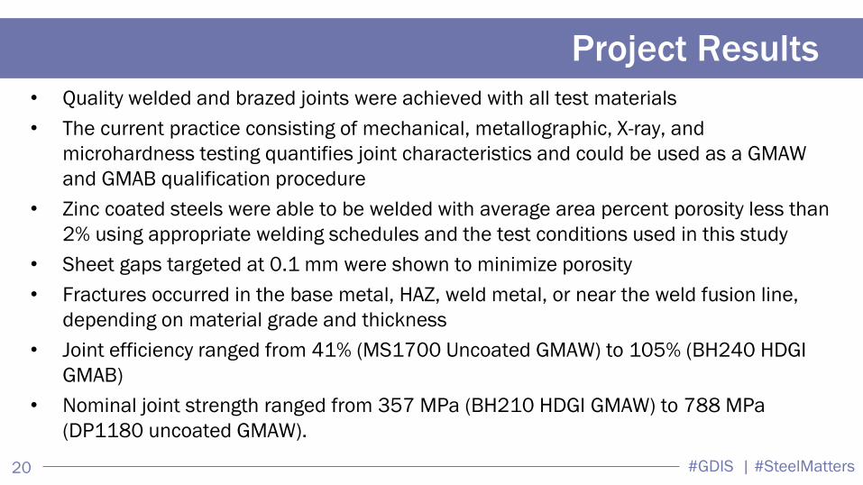
• Quality welded and brazed joints were achieved with all test materials
• The current practice consisting of mechanical, metallographic, X-ray, and
microhardness testing quantifies joint characteristics and could be used as a GMAW
and GMAB qualification procedure
• Zinc coated steels were able to be welded with average area percent porosity less than
2% using appropriate welding schedules and the test conditions used in this study
• Sheet gaps targeted at 0.1 mm were shown to minimize porosity
• Fractures occurred in the base metal, HAZ, weld metal, or near the weld fusion line,
depending on material grade and thickness
• Joint efficiency ranged from 41% (MS1700 Uncoated GMAW) to 105% (BH240 HDGI
GMAB)
• Nominal joint strength ranged from 357 MPa (BH210 HDGI GMAW) to 788 MPa
(DP1180 uncoated GMAW).
#GDIS | #SteelMatters 21
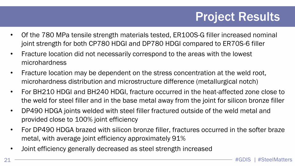
Project Results
• Of the 780 MPa tensile strength materials tested, ER100S-G filler increased nominal
joint strength for both CP780 HDGI and DP780 HDGI compared to ER70S-6 filler
• Fracture location did not necessarily correspond to the areas with the lowest
microhardness
• Fracture location may be dependent on the stress concentration at the weld root,
microhardness distribution and microstructure difference (metallurgical notch)
• For BH210 HDGI and BH240 HDGI, fracture occurred in the heat-affected zone close to
the weld for steel filler and in the base metal away from the joint for silicon bronze filler
• DP490 HDGA joints welded with steel filler fractured outside of the weld metal and
provided close to 100% joint efficiency
• For DP490 HDGA brazed with silicon bronze filler, fractures occurred in the softer braze
metal, with average joint efficiency approximately 91%
• Joint efficiency generally decreased as steel strength increased

#GDIS | #SteelMatters 22
For More Information
Richard Paul
Auto/Steel Partnership
248.875.7336
Min Kuo, PhD
ArcelorMittal
248.358.9245