Embed Size (px)
Citation preview

Gas Freestanding Range—Technical Information
May 2006 16027222 © 2006 Maytag Services Replaces 16022499
1
AGR5715QD* MGR5754QD* MGR5755QD* MGR5765QD* • Due to possibility of personal injury or property damage, always contact an authorized technician for servicing or
repair of this unit. • Refer to Service Manual 16022498 for detailed installation, operating, testing, troubleshooting, and disassembly
instructions.
CAUTION! All safety information must be followed as provided in Service Manual 16022498.
! WARNING To avoid risk of electrical shock, personal injury, or death, disconnect power and gas to range before servicing, unless testing requires power and/or gas.
Models AGR5715QD* MGR5755QD MGR5754QD*, MGR5765QD*
Power Source Electrical rating 120 VAC 120 VAC 120 VAC Amperage 15 Amp max. 15 Amp max. 15 Amp max. Frequency 60 Hz 60 Hz 60 Hz
Water Column Pressure Natural 4 in. W.C.P. 4 in. W.C.P. 4 in. W.C.P. LP/Propane 10 in. W.C.P. 10 in. W.C.P. 10 in. W.C.P.
Surface Burner (BTU Nat. / LP) Small 5,000 4,000 N/A N/A 5,000 4,000 Medium 9,200 9,100 9,200 9,100 9,200 9,100 Large 12,000 10,000 12,000 10,000 16,000 14,000
Oven Burner (BTU Nat./LP) Bake 18,000 18,000 18,000 18,000 18,000 18,000 Broil 13,000 13,000 13,000 13,000 13,000 13,000
Oven Interior Dimensions in. (cm) Height 19 - 3/16 (48.7) 19 - 3/16 (48.7) 19 - 3/16 (48.7) Width 24 – ¼ (61.5) 24 – ¼ (61.5) 24 – ¼ (61.5) Depth 19 - 3/8 (49.2) 19 - 3/8 (49.2) 19 - 3/8 (49.2)
Product Exterior Dimensions in. (cm) Height overall 47 - 3/8 (120.3) 47 - 3/8 (120.3) 47 - 3/8 (120.3) Width 29 - 7/8 (75.8) 29 - 7/8 (75.8) 29 - 7/8 (75.8) Depth oven door closed with handle 29 (73.6) 29 (73.6) 29 (73.6) Clearance with oven door open 48 - 7/8 (124.1) 48 - 7/8 (124.1) 48 - 7/8 (124.1) Height of cooktop 36 (91.4) 36 (91.4) 36 (91.4)
Unit Features Removable counterbalanced oven door with viewing window
X X X
Interior oven light X X X Automatic oven door latch X X X Child lockout X X X 12 hour automatic shut off X X X Porcelain broiler pan and grid X X X Removable full width storage drawer X X X 2 standard racks - 8 positions X X X
Weight lbs. (kg) Crated 225 (102.0) 230 (104.3) 230 (104.3) Uncrated 210 (95.2) 215 (97.5) 215 (97.5)

Component Testing Procedures
! WARNING To avoid risk of electrical shock, personal injury, or death, disconnect power and gas to range before servicing, unless testing requires power and/or gas.
16027222 May 2006 Replaces 16022499 © 2006 Maytag Services
2
Illustration Component Test Procedure Results
Oven light socket Test continuity of receptacle terminals. Measure voltage at oven light .............
Indicates continuity with bulb inserted. 120 VAC, see wiring diagram for terminal identification. If voltage is not present at oven light, check wiring.
Rocker switch Measure continuity of switch positions:
Closed .............................................Open................................................
Continuity. Infinite.
COMNO
NC
Door lock switch Switch connection in following positions: Not engaged.................................... Engaged ..........................................
Normally open. COM-NO=Open, COM-NC=Closed. COM-NO=Closed, COM-NC=Open.
NCNO
C
Door plunger switch Remove switch from unit and measure the following points: C-NO ...............................................
Plunger in: ........ Continuity. Plunger out: ...... Infinite.
Autolatch assembly with switch
Disconnect wires and test for continuity per wiring diagram...............
See wiring diagram for schematic layout. Refer to Parts Manual for correct autolatch switch.
Door latch assembly
Disconnect wires and test for continuity per wiring diagram...............
See wiring diagram for schematic layout. Refer to Parts Manual for correct autolatch switch associated with the correct manufacturing number.
Bake burner Verify gas is supplied .......................... Orifice adjusted for Natural or LP. Check for obstructions, contamination in ports or damage .......
Gas is supplied. Clean with hot soapy water and dry completely. Replace if punctured or torn.
Broil burner Verify gas is supplied .......................... Verify proper orifice installed for Natural or LP. Check for obstructions, contamination in ports or damage .......
Gas is supplied. Clean with hot soapy water and dry completely. Replace if punctured or torn.
Ignitor Test for voltage at terminals............... Test for the amount of amperage in the circuit ...........................................(Ignitor may glow, but not have sufficient amperage to open valve).
120 VAC. 3.2-3.6 Amps.
Temperature sensor Measure resistance............................. Approximately 1100 Ω at room temperature 80° F.
Component Testing Procedures
! WARNING To avoid risk of electrical shock, personal injury, or death, disconnect power and gas to range before servicing, unless testing requires power and/or gas.
May 2006 16027222 © 2006 Maytag Services Replaces 16022499
3
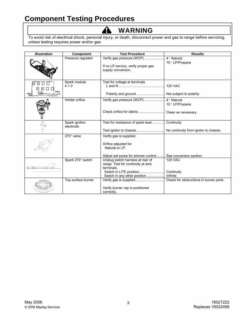
Illustration Component Test Procedure Results
Pressure regulator Verify gas pressure (WCP)..................... If on LP service, verify proper gas supply conversion.
4" Natural 10" LP/Propane
GND L or NInput
Spark module 4 + 0
Test for voltage at terminals L and N ............................................... Polarity and ground.............................
120 VAC Not subject to polarity
Holder orifice Verify gas pressure (WCP)..................... Check orifice for debris...........................
4" Natural 10" LP/Propane Clean as necessary.
Spark ignition electrode
Test for resistance of spark lead............. Test ignitor to chassis.............................
Continuity No continuity from ignitor to chassis.
270° valve Verify gas is supplied. Orifice adjusted for Natural or LP. Adjust set screw for simmer control ........
See conversion section.
Spark 270° switch Unplug switch harness at rear of range. Test for continuity at wire terminals. Switch in LITE position..........................Switch in any other position ..................
120 VAC Continuity Infinite
Top surface burner Verify gas is supplied.............................. Verify burner cap is positioned correctly.
Check for obstructions in burner ports.

Control Testing Procedures
! WARNING To avoid risk of electrical shock, personal injury, or death, disconnect power and gas to range before servicing, unless testing requires power and/or gas.
16027222 May 2006 Replaces 16022499 © 2006 Maytag Services
4
Controller Feature Procedure Results
M1 Oven temperature adjustment
Press BAKE pad. Enter 550 on the digit-pad. Immediately press and hold BAKE pad for 3 to 5 seconds. Oven can be adjusted from -35 to +35 degrees in 5-degree increments by pressing AUTOSET pad. To avoid over adjusting the oven, move temperature 5 degrees each time. Wait 4 seconds for the data entry timer to expire to accept the change. Temperature adjustment will be retained even through a power failure.
While increasing or decreasing oven temperature, this does not affect self-cleaning temperature.
M1 Temperature display Press and hold Cancel and Bake pads for 3 to 5 seconds.
Toggles temperature display between °F and °C.
M1 Clock display Press and hold Cancel and Clock pads for 3 to 5 seconds.
Toggles clock display on and off.
M1 24-hour Clock Press and hold Cancel and Delay pads for 3 to 5 seconds.
Toggles time display between 12 or 24 hour format.
M1 Factory default Press and hold Cancel and Keep Warm pads for 3 to 5 seconds.
Allows the clock to be reset to factory settings.
M1 12-hour off Control will automatically cancel any cooking operation and remove all relay drives 12 hours after the last pad touch.
See Sabbath mode to disable.
M1 Sabbath mode Hold CLOCK pad for 3 to 5 seconds to activate Sabbath mode. Hold CLOCK pad for 3 to 5 seconds to disable Sabbath mode.
"SAb" flashes for 5 seconds. Display returns to time of day. All pad inputs are disabled except for CANCEL and CLOCK pads. This mode disables the normal 12 hour shutoff to allow operation of the bake mode for a maximum of 72 hours.
M1 Child lock out Press and hold Cancel and Cook & Hold pads for 3 to 5 seconds. "OFF" will display where the temperature normally appears. "LOCK" will display flashing while door is locking. To reactivate the control, press and hold Cancel and Cook & Hold pads for 3 to 5 seconds.
Safety feature that used to prevent children from accidentally programming the oven. It disables the electronic oven control. Child lockout features must be reset after a power failure.
M1 Diagnostic code display
Press and hold Up Arrow pad and Power Up the unit. Cycle through the codes using the number pads 1 through 5.
The last 5 diagnostic codes will be stored in the non-volatile memory. See "Description of Error Codes" for explanation.

Control Testing Procedures
! WARNING To avoid risk of electrical shock, personal injury, or death, disconnect power and gas to range before servicing, unless testing requires power and/or gas.
May 2006 16027222 © 2006 Maytag Services Replaces 16022499
5
"Quick Test" Mode for M1 Electronic Range Control (ERC) Follow procedure below to use the quick test mode. Entries must be made within 32 seconds of each other or the control will exit the quick test mode.
1. Press and hold CANCEL and BROIL pads for 3 to 5 seconds. 2. Once the control has entered the "Quick Test" mode, release both pads. 3. Press each of the following pads indicated in the table below.
NOTE: Pressing the pad once activates the response. Press the pad a second time deactivates the response.
NOTE: This mode must be entered within the first 5 minutes of power up.
NOTE: If the temperature sensor reaches 400° F, the Quick Test mode will be disabled.
Display will indicate the following: Key Operation
[Bake] Bake relay activated [Broil] Broil relay activated [Keep Warm] N\A [Cook&Hold] Last Diagnostic Code displayed [Clean] MDL relay activated (lock and unlock) [Delay] (M1) EEPROM Version Number displayed [Timer] Main Code Version Number displayed [Clock] All Segments On [More +] Even Segments On [Less –] Odd Segments On [Cancel] End Factory Test Mode
Description of Error Codes Error diagnostic codes can only be viewed by entering the Diagnostic Code Display Mode. Each error code is four digits long and is created based on the following table.
Digit Description 1st Primary System: 1 – Local to the control circuit board
3 – Sensor or meat probe 4 – Control input 9 – Door lock
2nd Measurable: d – Diagnostic: measurable parameter c – Control related, replace control
3rd Secondary System: Sequential numbering 4th Oven Cavity: 1 – Upper oven (or single cavity oven)
2 – Lower oven c – Control specific
Diagnostic Code Display Mode can be activated by pressing and holding the AUTOSET pad for 3 to 5 seconds at power-up. Diagnostic Code Display Mode can only be started while powering up the control.

Control Testing Procedures
! WARNING To avoid risk of electrical shock, personal injury, or death, disconnect power and gas to range before servicing, unless testing requires power and/or gas.
16027222 May 2006 Replaces 16022499 © 2006 Maytag Services
6
Diagnostic Code Checking
Code Description When Checked Detection 1c1c Shorted key Always 1 minute 1c2c Keyboard tail disconnected Always 1 minute 1c31 Cancel key circuit problem Always 20 seconds 1c6c EEPROM error When accessing EEPROM 3 tries 1c7c Control not calibrated Always 3 tries 1c8c Cooking program error Cook or clean programmed 3 tries 1d11 Runaway temp (650° F), door unlocked Latch unlocked 1 minute 1d21 Runaway temp (950° F), door locked Latch locked 1 minute 3d11 Sensor open Cook or clean active 20 seconds 3d21 Sensor shorted Cook or clean active 20 seconds 4d11 Door switch position failure Clean or keyboard Lockout
active 1 minute
4d51 Door switch circuit failure Convect, Clean or Keyboard Lockout programmed
1 minute
9d11 Latch will not lock Latch should be locked See Note 6 9d21 Latch will not unlock Latch should be unlocked See Note 6 9d31 Latch state unknown, both locked and unlocked Latch should be locked or when
lock attempted See Note 6
Diagnostic Code Handling
Code Measurable What is Displayed Action Taken By Control
1c1c Keypress Nothing
Disables audible for affected key depression Disables all outputs 1, 2 Disables lights and timers
1c2c Keyboard loop improper value Nothing Disables audible for key depression Disables all outputs 1 Disables lights and timers
1c31 Cancel key improper value BAKE flashes 3 Disables all outputs for cavity 1 1c6c No response from EEPROM Nothing Disables all outputs 1 1c7c Calibration value out of range "CAL" in the time digits Completely disables oven 4 1c8c CRC invalid Nothing Cancels active cook functions 1d11 Sensor resistance > 2237 Ohms BAKE flashes 3 Disables all cook functions for cavity 1d21 Sensor resistance > 2787 Ohms BAKE flashes 3 Disables all cook functions for cavity 3d11 Sensor resistance > Infinite Ohms BAKE flashes 3 Disables all cook functions for cavity 3d21 Sensor resistance > 0 Ohms BAKE flashes 3 Disables all cook functions for cavity 4d11 Door switch not closed when door is
locked Nothing Disables Clean and Lockout functions 5
4d51 Door switch not open or closed
Nothing
Disables Convect, Clean, and Lockout functions 4, 5
Turn off light and disable light from door switch
9d11 Lock switch not closed LOCK flashes 3 Disables Clean and Lockout functions 4
9d21 Unlock switch not closed LOCK flashes 3 Disables Clean and Lockout functions 4
9d31 Lock and unlock switches both closed LOCK flashes 3 Disables Clean and Lockout functions 4

Control Testing Procedures
! WARNING To avoid risk of electrical shock, personal injury, or death, disconnect power and gas to range before servicing, unless testing requires power and/or gas.
May 2006 16027222 © 2006 Maytag Services Replaces 16022499
7
NOTES: 1 "Action Taken" applies as long as the condition exists. If the condition improves, the control recovers. 2 If there is a cook function or timer active, the function continues. The user cannot edit the function, and [Cancel] will cancel the cook
mode. 3 Flash rate: 0.2 seconds on, 0.1 second off. Pressing any key will clear the display until the fault clears and is re-triggered. 4 "Action Taken" applies until there is a POR (Power On Reset ["hard reset"]). 5 If the control believes the door is locked, it will attempt to unlock it when the function cancels and the cavity temperature cools. 6 Special conditions for latch faults (9dxx):
• A known good unlock position is defined as when the unlock switch reads closed and lock switch reads open. • A known good lock position is defined as when the unlock switch reads open and lock switch reads closed. • A faulted switch means the switch input is reading an invalid state, neither open nor closed. • Once a latch fault occurs, latch movement is disabled until there is a POR. An error tone will sound if a function requiring a
faulted latch is attempted. • If at POR, the latch is not at a known good unlock position:
• If the latch is at a good lock position, it will attempt to unlock when the RTD (Resistance Temperature Device) temperature is below 400° F.
• If the latch is not at a good lock position, the control will fault. • If a latch fault occurs while the RTD is above the lock temperature, the latch will not try to move, but the fault is still logged
to EEPROM after the first stage of detection. • The Display column for latch faults applies 1) If the latch was moving when the fault occurred; 2) If the latch is already in a
known locked state when the fault occurs.
• LOCK flashes after a fault is detected and until the unlocked position is achieved. The unlock position may be identified by a successful unlock switch closure, or as the result of timing when the unlock switch is not functioning properly.
• If the last known good position was unlock (e.g. baking, or idle) and a latch fault occurs, the motor is never moved. The fault is logged to EEPROM and is not seen by the user.
• The detection for latch faults is in two stages. The first stage is to let the control recover without moving the latch. Then: • If the latch was previously at a known good unlock position, the latch will not move and the control will fault. • If the control was previously in a known good lock position:
• If the RTD is below 400° F, the latch will attempt to recover to it’s proper position (up to three revolutions). If it cannot, the control will fault and the latch will move to a calculated unlock position.
• If the RTD is at or above 400° F, the control will fault. When the RTD cools to below 400° F, the control will attempt to recover to a good unlock position (up to three revolutions). If it cannot, the control will fault and the latch will move to a calculated unlock position.
• NOTE: If the unlock position cannot be found, this may result in a second fault, the first fault occurring when the latch request was locked, and the second when the latch request is unlocked.
• If the latch is moving when the fault occurs, the control will bypass the first stage of detection and immediately try to find it’s proper position. If it cannot, the control will fault and the latch will move to a calculated unlock position.
• Affected DLBs (Double Line Breaks) and loads are disabled during detection. • If the control is in a known good unlock position and the lock switch becomes faulted:
• The control will not fault. • If a function requiring latch movement is attempted while the lock switch is faulted, the control will sound an error
tone and the function will be disabled. • If the control is in a known good lock position and the unlock switch becomes faulted:
• The control will not fault. • After the function is canceled and unlock is attempted, the control will attempt to unlock the latch according to the
procedures in these notes.

Wiring Diagram and Schematic
! WARNING To avoid risk of electrical shock, personal injury, or death, disconnect power and gas to range before servicing, unless testing requires power and/or gas.
16027222 May 2006 Replaces 16022499 © 2006 Maytag Services
8
Wiring Diagram, MGR5765QDS Series 13 and earlier, AGR5715QD*, MGR5765QDB/Q/W

Wiring Diagram and Schematic
! WARNING To avoid risk of electrical shock, personal injury, or death, disconnect power and gas to range before servicing, unless testing requires power and/or gas.
May 2006 16027222 © 2006 Maytag Services Replaces 16022499
9
Schematic Diagram, MGR5765QDS Series 13 and earlier, AGR5715QD*, MGR5765QDB/Q/W

Wiring Diagram and Schematic
! WARNING To avoid risk of electrical shock, personal injury, or death, disconnect power and gas to range before servicing, unless testing requires power and/or gas.
16027222 May 2006 Replaces 16022499 © 2006 Maytag Services
10
Wiring Diagram, MGR5754QD*, MGR5755QD*
Wiring Diagram and Schematic
! WARNING To avoid risk of electrical shock, personal injury, or death, disconnect power and gas to range before servicing, unless testing requires power and/or gas.
May 2006 16027222 © 2006 Maytag Services Replaces 16022499
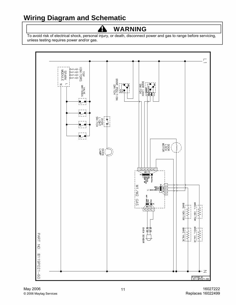
11

Wiring Diagram and Schematic
! WARNING To avoid risk of electrical shock, personal injury, or death, disconnect power and gas to range before servicing, unless testing requires power and/or gas.
16027222 May 2006 Replaces 16022499 © 2006 Maytag Services
12
Schematic Diagram, MGR5754QD*, MGR5755QD*

Wiring Diagram and Schematic
! WARNING To avoid risk of electrical shock, personal injury, or death, disconnect power and gas to range before servicing, unless testing requires power and/or gas.
May 2006 16027222 © 2006 Maytag Services Replaces 16022499
13
Wiring Diagram, MGR5765QDS, Series 14 and later

Wiring Diagram and Schematic
! WARNING To avoid risk of electrical shock, personal injury, or death, disconnect power and gas to range before servicing, unless testing requires power and/or gas.
16027222 May 2006 Replaces 16022499 © 2006 Maytag Services
14
Schematic Diagram, MGR5765QDS, Series 14 and later