Embed Size (px)
Citation preview
GAS FLOW MULTI-METER
MODELS 5300 / 5310 /
5320 / 5330 / 5303
OPERATION AND SERVICE MANUAL
P/N 6011689, REVISION F
MARCH 2021


iii
Warranty
Copyright
TSI Incorporated / 2019-2021 / All rights reserved.
Address
TSI Incorporated / 500 Cardigan Road / Shoreview, MN 55126 USA
WARNING
TSI® flow meters employ a heated platinum sensor. They should not be used with flammable or explosive gases or mixtures.
CAUTION
TSI® flow meters are not medical devices under FDA 510k and in no situation should they be utilized for human respiration measurements.
LIMITATION OF WARRANTY AND LIABILITY (effective February 2015) (For country-specific terms and conditions outside of the USA, please visit www.tsi.com.)
Seller warrants the goods, excluding software, sold hereunder, under normal use and service as described in the operator's manual, to be free from defects in workmanship and material for 12 months, or if less, the length of time specified in the operator's manual, from the date of shipment to the customer. This warranty period is inclusive of any statutory warranty. This limited warranty is subject to the following exclusions and exceptions:
a. Hot-wire or hot-film sensors used with research anemometers, and certain other components when indicated in specifications, are warranted for 90 days from the date of shipment;
b. Pumps are warranted for hours of operation as set forth in product or operator’s manuals;
c. Parts repaired or replaced as a result of repair services are warranted to be free from defects in workmanship and material, under normal use, for 90 days from the date of shipment;
d. Seller does not provide any warranty on finished goods manufactured by others or on any fuses, batteries or other consumable materials. Only the original manufacturer's warranty applies;
e. This warranty does not cover calibration requirements, and seller warrants only that the instrument or product is properly calibrated at the time of its manufacture. Instruments returned for calibration are not covered by this warranty;
f. This warranty is VOID if the instrument is opened by anyone other than a factory authorized service center with the one exception where requirements set forth in the manual allow an operator to replace consumables or perform recommended cleaning;
g. This warranty is VOID if the product has been misused, neglected, subjected to accidental or intentional damage, or is not properly installed, maintained, or cleaned according to the requirements of the manual. Unless specifically authorized in a separate writing by Seller, Seller makes no warranty with respect to, and shall have no liability in connection with, goods which are incorporated into other products or equipment, or which are modified by any person other than Seller.
The foregoing is IN LIEU OF all other warranties and is subject to the LIMITATIONS stated herein. NO OTHER EXPRESS OR IMPLIED WARRANTY OF FITNESS FOR PARTICULAR PURPOSE OR MERCHANTABILITY IS MADE. WITH RESPECT TO SELLER’S BREACH OF THE IMPLIED WARRANTY AGAINST INFRINGEMENT, SAID WARRANTY IS LIMITED TO CLAIMS OF DIRECT INFRINGEMENT AND EXCLUDES CLAIMS OF CONTRIBUTORY OR INDUCED INFRINGEMENTS. BUYER’S EXCLUSIVE REMEDY SHALL BE THE RETURN OF THE PURCHASE PRICE DISCOUNTED FOR REASONABLE WEAR AND TEAR OR AT SELLER’S OPTION REPLACEMENT OF THE GOODS WITH NON-INFRINGING GOODS.
TO THE EXTENT PERMITTED BY LAW, THE EXCLUSIVE REMEDY OF THE USER OR BUYER, AND THE LIMIT OF SELLER'S LIABILITY FOR ANY AND ALL LOSSES, INJURIES, OR DAMAGES CONCERNING THE GOODS (INCLUDING CLAIMS BASED ON CONTRACT, NEGLIGENCE, TORT, STRICT LIABILITY OR OTHERWISE) SHALL BE THE RETURN OF GOODS TO SELLER AND THE REFUND OF THE PURCHASE PRICE, OR, AT THE OPTION OF SELLER, THE REPAIR OR REPLACEMENT OF THE GOODS. IN THE CASE OF SOFTWARE, SELLER WILL REPAIR OR REPLACE DEFECTIVE SOFTWARE OR IF UNABLE TO DO SO, WILL REFUND THE PURCHASE PRICE OF THE SOFTWARE. IN NO EVENT SHALL SELLER BE LIABLE FOR LOST PROFITS, BUSINESS INTERRUPTION, OR ANY SPECIAL, INDIRECT, CONSEQUENTIAL OR INCIDENTAL DAMAGES. SELLER SHALL NOT BE RESPONSIBLE FOR INSTALLATION, DISMANTLING OR REINSTALLATION COSTS OR CHARGES. No Action, regardless of form, may be brought against Seller more than 12 months after a cause of action has accrued. The goods returned under warranty to Seller's factory shall be at Buyer's risk of loss, and will be returned, if at all, at Seller's risk of loss.
Buyer and all users are deemed to have accepted this LIMITATION OF WARRANTY AND LIABILITY, which contains the complete and exclusive limited warranty of Seller. This LIMITATION OF WARRANTY AND LIABILITY may not be amended, modified or its terms waived, except by writing signed by an Officer of Seller.
Service Policy Knowing that inoperative or defective instruments are as detrimental to TSI attention to any problems. If any malfunction is discovered, please contact your nearest sales office or representative, or call TSI's Customer Service department at (800) 680-1220 (USA) or (001 651) 490-2860 (International) or visit www.tsi.com.

iv Gas Flow Multi-Meter Models 5300/5310/5320/5330/5303
Trademarks TSI and the TSI logo are registered trademarks of TSI Incorporated in the United States and may be protected under other country’s trademark registrations. FLO-Sight is a trademark of TSI Incorporated.

v
Contents
Warranty ............................................................................................................................................................ iii
Contents ............................................................................................................................................................. v
CHAPTER 1 Unpacking and Parts Identification ......................................................................................... 1
List of Standard Components ............................................................................................................ 1 5300 Series High Flow Gas Flow Multi-Meter ............................................................................ 1
Standard Accessory Kit ..................................................................................................................... 2 5300 Series Standard Accessory Kit (53000) ............................................................................. 2
Low Pressure Measurement Kit ........................................................................................................ 3 5300 Series Low Pressure Measurement Kit (5300-LPMK) ....................................................... 3
Optional Accessories ......................................................................................................................... 3 5300 Series Accessories ............................................................................................................ 3 5000 Series Universal Accessories ............................................................................................ 4
CHAPTER 2 Meter Setup ................................................................................................................................. 7
Instrument Overview ......................................................................................................................... 7 5300 Series High Flow Gas Flow Multi-Meter ............................................................................ 7
Supplying Power ............................................................................................................................... 8 USB Hub Cable ........................................................................................................................... 8
Communications ................................................................................................................................ 9 USB-C to USB-A Cable .............................................................................................................. 9 USB-A to RS-232 Cable ........................................................................................................... 10
Connecting Inlet Filter ..................................................................................................................... 11 Changing Tube Ends ....................................................................................................................... 12 Using 0.5 inch or 15 mm Tube Ends ............................................................................................... 13 Low Pressure Measurement Kit ...................................................................................................... 14
5300 Series Low Pressure Measurement Kit (5300-LPMK) ..................................................... 14
CHAPTER 3 Meter Operation ........................................................................................................................ 17
Getting Started ................................................................................................................................ 17 Power Button ............................................................................................................................ 17 Initialization and Warm-Up ........................................................................................................ 17 Touchscreen Display ................................................................................................................ 17
Measurement Parameters ............................................................................................................... 17 Flow Measurement ................................................................................................................... 17 Temperature Measurement ...................................................................................................... 18 Absolute Pressure Measurement ............................................................................................. 18 Low Differential Pressure Measurement ................................................................................... 18 Relative Humidity Measurement ............................................................................................... 18 Volume Measurement ............................................................................................................... 18 Totalizer Measurement ............................................................................................................. 18
Units of Measurement ..................................................................................................................... 19 Type of Gas ..................................................................................................................................... 19
Model Numbers based on Gas Calibration ............................................................................... 19 Meter Configuration ......................................................................................................................... 20 Data Logging ................................................................................................................................... 20
Preset Logging Configurations and Sample Points .................................................................. 20
CHAPTER 4 Touchscreen Navigation ......................................................................................................... 21
Display Overview ............................................................................................................................. 21 Meter Home Screen .................................................................................................................. 21 Menu Screen ............................................................................................................................. 22 Measurements .......................................................................................................................... 22

vi Gas Flow Multi-Meter Models 5300/5310/5320/5330/5303
Type of Gas ............................................................................................................................... 22 Flow Directional Indicators ........................................................................................................ 23 Pause/Play Display ................................................................................................................... 23
Configuring the Meter ...................................................................................................................... 24 Measurement Parameters ........................................................................................................ 24 Units of Measurement ............................................................................................................... 24 Flow Conditions ......................................................................................................................... 25 Type of Gas ............................................................................................................................... 25 Locking the Meter ...................................................................................................................... 26
Volume and Triggers ....................................................................................................................... 27 Setting Triggers ......................................................................................................................... 28 Making Volume Measurements ................................................................................................ 29
Data Logging ................................................................................................................................... 30 Logging Parameters .................................................................................................................. 30 Log Data .................................................................................................................................... 31 Export Data Files ....................................................................................................................... 31 Delete Data Files ....................................................................................................................... 32
Rotate Screen .................................................................................................................................. 33 Alerts ................................................................................................................................................ 33 Meter Information............................................................................................................................. 34
Updating Firmware .................................................................................................................... 35 Device Settings ................................................................................................................................ 36 Reset Device Settings ..................................................................................................................... 38
Zero Low Pressure .................................................................................................................... 39 Reset Totalizer .......................................................................................................................... 39 Reset Device to Factory Defaults ............................................................................................. 39
CHAPTER 5 Maintenance .............................................................................................................................. 41
Flow Sensor ..................................................................................................................................... 41 Re-Certification ................................................................................................................................ 41 Damaged Tube End Connections ................................................................................................... 41 Cases ............................................................................................................................................... 41 Storage ............................................................................................................................................ 42
CHAPTER 6 Troubleshooting ....................................................................................................................... 43
Technical Contacts .......................................................................................................................... 44 Returning the Gas Flow Multi-Meter for Service ............................................................................. 44
CHAPTER 7 FLO-Sight™ PC Software ........................................................................................................ 45
CHAPTER 8 Serial Command Set ................................................................................................................ 47
Commands for Flow Rate, Temperature, Pressure, and Volume ................................................... 47 Measurement Setup Commands ..................................................................................................... 47 Miscellaneous Commands .............................................................................................................. 48
APPENDIX A 5300 Series Flow Multi-Meter Specifications ...................................................................... 49
5300 Series Pressure Drop ............................................................................................................. 51 5300 Series Dimensions .................................................................................................................. 52
APPENDIX B Standard Flow Rate vs. Volumetric Flow Rate ................................................................... 53
APPENDIX C Humidity Compensation ........................................................................................................ 55
Disable / Enable Humidity Compensation ................................................................................. 55
APPENDIX D Remote Flow ........................................................................................................................... 57
Theory of Operation ......................................................................................................................... 57 Remote Flow Setup ......................................................................................................................... 57

1
C H A P T E R 1 Unpacking and Par ts Ident i f ica t ion
List o f Standard Components
Carefully unpack the instrument and accessories from the shipping container. Check the individual
parts against the list of components in tables below. If any parts are missing or damaged, notify
TSI® immediately.
5300 Series High Flow Gas Flow Multi-Meter
Qty. Item Description Part/Model
1 High Flow Gas Flow Multi-Meter, 22-mm ISO tube ends
Measures Flow, Temperature, Absolute Pressure
5300
High Flow Gas Flow Multi-Meter, 22-mm ISO tube ends
Measures Flow, Volume, Temperature, Absolute Pressure, Differential
Pressure
5310
High Flow Gas Flow Multi-Meter, 22-mm ISO tube ends
Measures Flow, Volume, Temperature, Absolute Pressure, Differential
Pressure, Relative Humidity
5320
High Flow Gas Flow Multi-Meter (High Accuracy), 22-mm ISO tube ends,
includes Tabletop Stand
Measures Flow, Volume, Temperature, Absolute Pressure, Differential
Pressure, Relative Humidity
5330
High Flow Gas Flow Multi-Meter (Wide Accuracy Spec), 22-mm ISO
tube ends
Measures Flow, Temperature, Absolute Pressure
5303
1 Calibration Certificate N/A
1 5300 Series Standard Accessory Kit 53000
1 Low Pressure Measurement Kit
(5310/5320/5330 models only)
5300-LPMK
1 License key for FLO-Sight™ PC Software
(Includes a free trial of the advanced version)
5000-PC
*FLO-Sight PC Software can be downloaded from www.tsi.com.
™FLO-Sight is a trademark of TSI Incorporated.

2 Gas Flow Multi-Meter Models 5300/5310/5320/5330/5303
Standard Accessory K i t
5300 Series Standard Accessory Kit (53000)
Item Description TSI® Part Number Picture
5300 Series 1/2 inch Tube Ends (2) 5300-05IN
5300 Series Inlet Filter Low Pressure 5300-IF-LP
5000 Series USB-C to USB-A Power
and Communications Cable (6 ft.)
5000-USBC-A
5000 Series Universal Power Supply
5.0 VDC ±5%, 500 mA maximum
5000-UPS
5000 Series USB Hub Cable 5000-HUB

Operation and Service Manual 3
Low Pressure Measurement K i t
5300 Series Low Pressure Measurement Kit (5300-LPMK)
Item Description Quantity Picture
22 mm (M/F) Airway Pressure
Fitting with Screen
2
1/8 inch ID x 1/4 inch OD Tubing 96 inches
Opt ional Accessor ies
5300 Series Accessories
Item Description TSI® Part Number Picture
5300 Series 22 mm M/15 mm F ISO Tube Ends (2)
5300-22MM
5300 Series 1/2 inch Tube Ends (2) 5300-05IN
5300 Series 15 mm ISO Tube Ends (2) 5300-15MM
5300 Series 3/4 inch Tube Ends (2) 5300-075IN
5300 Series High Pressure 3/8 inch NPT Tube Ends (2)
5300-375NPT
5300 Series End Caps (2) 5300-EC
4 Gas Flow Multi-Meter Models 5300/5310/5320/5330/5303
Item Description TSI® Part Number Picture
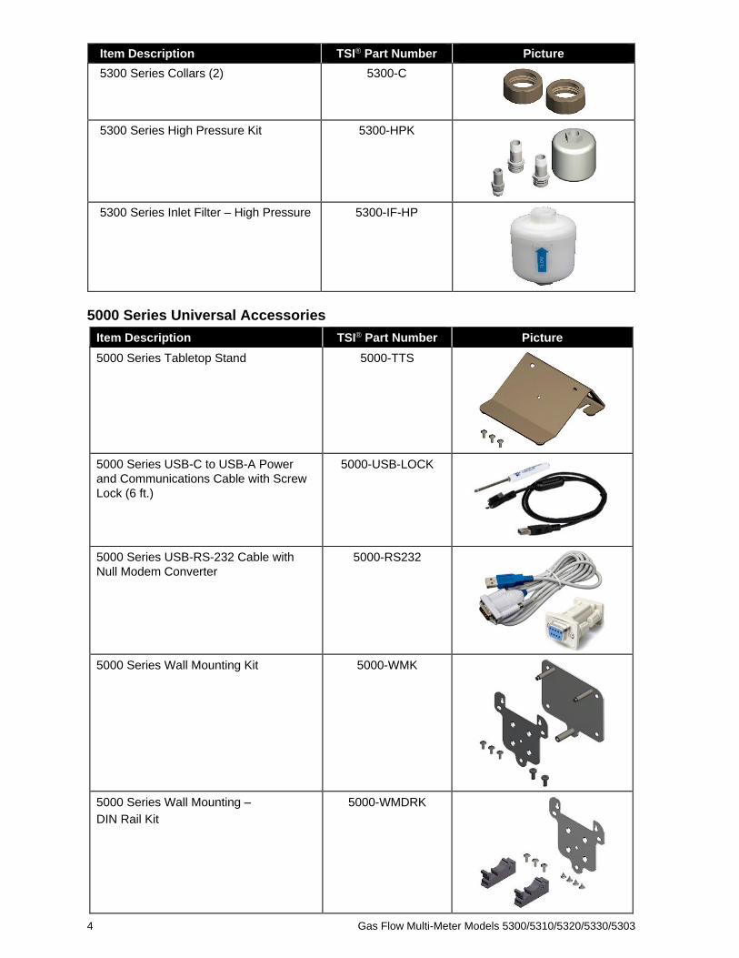
5300 Series Collars (2) 5300-C
5300 Series High Pressure Kit 5300-HPK
5300 Series Inlet Filter – High Pressure 5300-IF-HP
5000 Series Universal Accessories
Item Description TSI® Part Number Picture
5000 Series Tabletop Stand 5000-TTS
5000 Series USB-C to USB-A Power
and Communications Cable with Screw
Lock (6 ft.)
5000-USB-LOCK
5000 Series USB-RS-232 Cable with
Null Modem Converter
5000-RS232
5000 Series Wall Mounting Kit 5000-WMK
5000 Series Wall Mounting –
DIN Rail Kit
5000-WMDRK

Operation and Service Manual 5
Item Description TSI® Part Number Picture
5000 Series Wall Mounting –
Back Plate Only
5000-WMBP
5000 Series Wall Mounting –
Meter Plate Only
5000-WMMP
5000 Series Wall Mounting DIN Rail –
Clips Only (2)
5000-WMDRC
5000 Series Deluxe Carrying Case 5000-DCC
FLO-Sight™ PC Software
(Advanced Version)
5000-PC-ADV See Chapter 7 for more
information.

6 Gas Flow Multi-Meter Models 5300/5310/5320/5330/5303
(This page intentionally left blank)

7
C H A P T E R 2 Meter Setup
Inst rument Overv iew
5300 Series High Flow Gas Flow Multi-Meter
Meter Front
Meter Back
1. Power Button (On/Off) 5. USB-C Power / Communications Port
2. Color Touchscreen Display * 6. USB-A Communications Ports (2)
3. Interchangeable Tube Ends 7. Differential Pressure Ports
(5310 / 5320 / 5330 models only)
4. Mounting Inserts (M3 thread size) 8. Collars
* The touchscreen display is resistive and responds to applied pressure

8 Gas Flow Multi-Meter Models 5300/5310/5320/5330/5303
Supply ing Power
The 5300 Series Multi-Meter can be powered by connecting the USB-C to USB-A Power and
Communications Cable from the USB-C port on the meter to: 1) the 5000 Series Universal Power
Supply, 2) a computer, or 3) an alternative USB-compatible source that can provide 5 VDC.
(1)
(2)
(3)
Power Supply: 5.0 VDC ±5%, 500 mA maximum
USB Hub Cable
Some computer USB ports are not capable of sufficiently powering the meter. The meter may fail to
power on, or the meter may power on but be unable to complete the startup process.
If you are unable to power your meter from the computer, connect using the provided USB hub cable.
To do this, connect the USBC-A power cable to the USB hub cable, plug the hub cable into the USB-A
port of the computer, and plug the other end of the USBC-A cable into the USB-C port located on top
of the meter.

Operation and Service Manual 9
Communicat ions
USB-C to USB-A Cable
In addition to supplying power, the
5000 Series USB-C to USB-A cable
(5000-USBC-A) provides direct
communication between the Multi-
Meter and a computer. The graphic
to the right shows the connection
scheme.
You can view real-time
measurements and control your
meter through FLO-Sight™ PC
Software or through an alternative
program such as HyperTerminal® or
PuTTY using ASCII commands.
For more details, please refer to the
FLO-Sight™ PC Software Manual
or the Series 5200/5300 ASCII
Command Set Manual.
®HyperTerminal is a registered trademark of Hilgraeve, Incorporated
10 Gas Flow Multi-Meter Models 5300/5310/5320/5330/5303
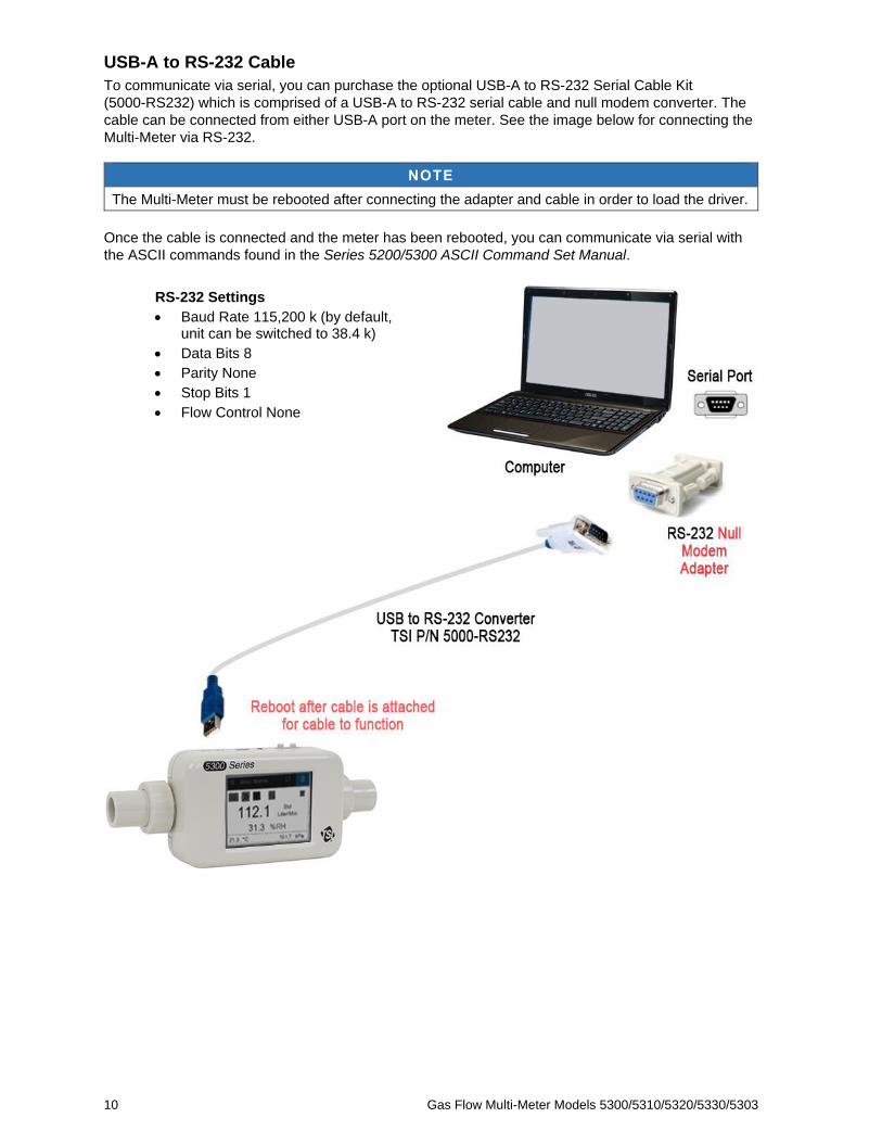
USB-A to RS-232 Cable
To communicate via serial, you can purchase the optional USB-A to RS-232 Serial Cable Kit
(5000-RS232) which is comprised of a USB-A to RS-232 serial cable and null modem converter. The
cable can be connected from either USB-A port on the meter. See the image below for connecting the
Multi-Meter via RS-232.
NOTE
The Multi-Meter must be rebooted after connecting the adapter and cable in order to load the driver.
Once the cable is connected and the meter has been rebooted, you can communicate via serial with
the ASCII commands found in the Series 5200/5300 ASCII Command Set Manual.
RS-232 Settings
• Baud Rate 115,200 k (by default, unit can be switched to 38.4 k)
• Data Bits 8
• Parity None
• Stop Bits 1
• Flow Control None

Operation and Service Manual 11
Connect ing In le t F i l ter
The 5300 Series Gas Flow Multi-Meters have an exposed thermal flow sensor that is highly sensitive
to foreign matter and particles within the gas flow. TSI® supplies inlet filters for both low pressure and
high pressure applications and recommends that these filters be used at all times while testing with the
instrument. After attaching the inlet filter, connect the flow tube to the inlet side of the filter.
If you are measuring a bidirectional gas flow and are concerned about foreign matter or particles
entering the flow stream from either side of your test setup, TSI® recommends an inlet filter be placed
on both sides of the meter.
CAUTION
Always use a filter on the inlet of the flow meter. Failure to filter the gas flow may
change the calibration and/or permanently damage the sensor.
NOTE
Connecting a second inlet filter or tube to the outlet side of the 5300 Series Gas Flow Multi-Meter
will create back pressure. In general, minimize back pressure on the meter to maintain the highest
possible accuracy.
See Appendix A for the pressure drop created by connecting the supplied inlet filters to the 5300
Series Multi-Meter along with additional specifications.

12 Gas Flow Multi-Meter Models 5300/5310/5320/5330/5303
Changing Tube Ends
The 5300 Series Gas Flow Multi-Meter incorporates interchangeable tube ends that can be easily
configured by you without the need for special tools or additional accessories. Follow the step-by-step
instructions below to remove and replace the 5300 Series Gas Flow Multi-Meter tube ends.
NOTE
5200 Series Low Flow Multi-Meter and 5300 Series High Flow Multi-Meter tube ends are not
interchangeable.
Step 1: Unscrew and remove the collars then remove the tube ends by pulling them straight out of
the meter.
Step 2: Select your desired size of tube ends and insert them into the meter while aligning the anti-
rotation notch on the tube end with the tab on the meter.
Step 3: After aligning the tube ends into the meter, slide the collars back on and tighten them by
rotating clockwise.
NOTE
Contact TSI® if you would like specifications for designing your own custom tube ends.

Operation and Service Manual 13
Using 0 .5 inch or 15 mm Tube Ends
When using a 5300 Series meter with 0.5 inch or
15-mm tube end adapters, if the filter is connected
as shown right then no further action is needed.
If the 0.5 inch or 15-mm tube ends are connected
directly to the instrument, you should select the
“Using 0.5 inch or 15 mm ends” Toggle Switch in
the meter’s Settings screen.
NOTE
The 5300 Series Flow Multi-Meter will still measure within its published accuracy specification even
if this recommendation is not followed, but selecting the toggle switch with this setup ensures the
most accurate flow measurement readings.
This toggle switch can be found by clicking
on the Settings button in the Menu header.
1. Select the Config tab.
2. Click the Edit button.
3. Click the toggle switch.
4. Select Save.

14 Gas Flow Multi-Meter Models 5300/5310/5320/5330/5303
Low Pressure Measurement K i t
TSI® includes a Low Pressure Measurement Kit (5300-LPMK) to utilize the low differential pressure
measurement available on models 5310, 5320, and 5330. The kit comes complete with the airway
pressure fittings and tubing needed to connect the breathing or test circuit to the Flow Multi-Meter. See
below for instructions on connecting the Low Pressure Measurement Kits to the 5300 Series.
NOTE
TSI® does not require that these kits be utilized to make differential pressure measurements but
provides them simply as a convenience.
5300 Series Low Pressure Measurement Kit (5300-LPMK)
Standard Setup: 22-mm ISO Tube Ends
Step 1: Locate and attach a 22-mm Airway Pressure Fitting to the outlet side tube end of the 5300
Series Multi-Meter with the barb facing up.
Step 2: Measure and cut a length of tubing and connect it from the Airway Pressure Fitting barb to
the (+) port on the Multi-Meter.
Step 3: Attach a filter (5300-IF-LP) to the inlet side tube end of the Multi-Meter.
Operation and Service Manual 15
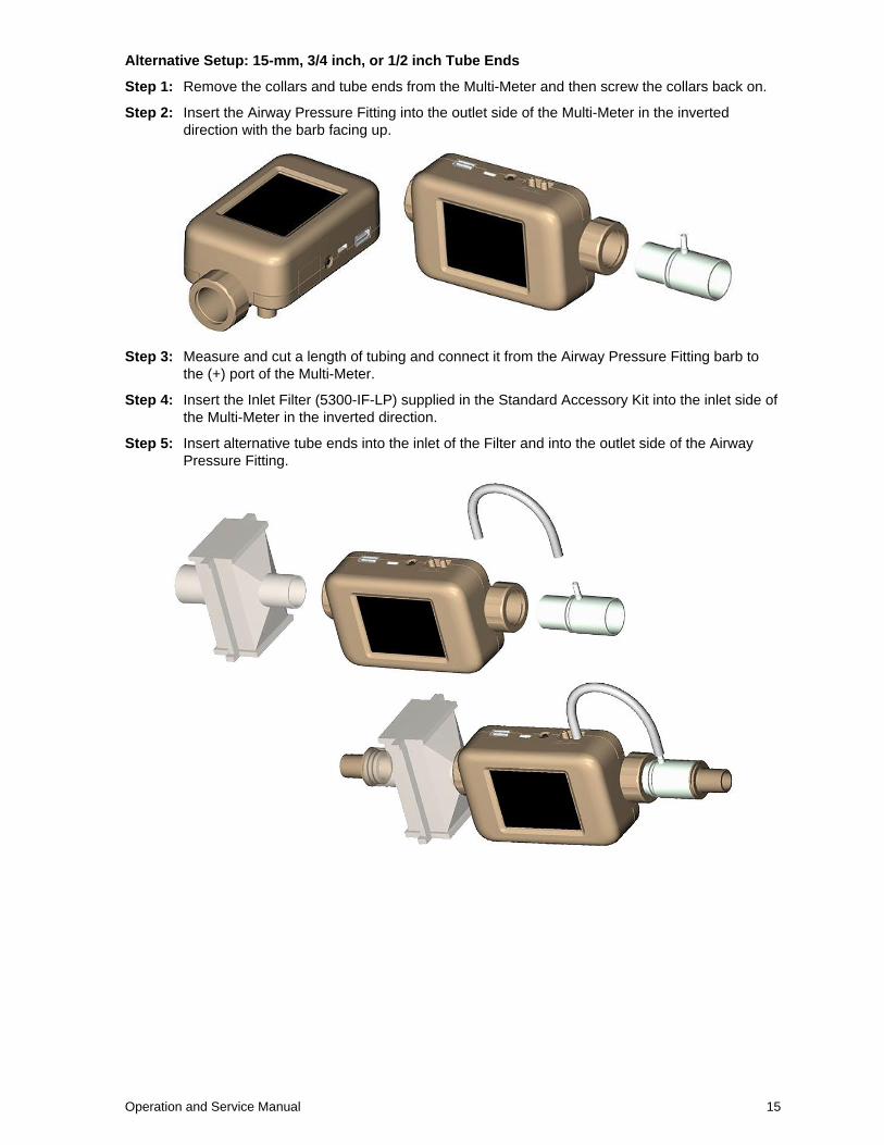
Alternative Setup: 15-mm, 3/4 inch, or 1/2 inch Tube Ends
Step 1: Remove the collars and tube ends from the Multi-Meter and then screw the collars back on.
Step 2: Insert the Airway Pressure Fitting into the outlet side of the Multi-Meter in the inverted
direction with the barb facing up.
Step 3: Measure and cut a length of tubing and connect it from the Airway Pressure Fitting barb to
the (+) port of the Multi-Meter.
Step 4: Insert the Inlet Filter (5300-IF-LP) supplied in the Standard Accessory Kit into the inlet side of
the Multi-Meter in the inverted direction.
Step 5: Insert alternative tube ends into the inlet of the Filter and into the outlet side of the Airway
Pressure Fitting.

16 Gas Flow Multi-Meter Models 5300/5310/5320/5330/5303
(This page intentionally left blank)
17
C H A P T E R 3 Meter Operat ion
CAUTION
TSI® flow meters are not medical devices under FDA 510k and in no situation should they be utilized for human respiration measurements.
Gett ing Star ted
Power Button
The Multi-Meter may turn itself on once it is supplied with power. If the meter does not turn on
automatically, press the Power button on top of the meter and the unit will power ON. To turn the
instrument OFF, press and hold the Power button for 5 seconds.
Initialization and Warm-Up
It takes approximately 40 seconds for the 5300 Series Gas Flow Multi-Meter to initialize and warm-up.
A TSI® splash screen will be displayed during this initialization period. Once this process has
completed, the Flow Multi-Meter will begin displaying measurements and users will be able to fully
operate meter. No additional meter warm-up time is needed.
Touchscreen Display
The 5300 Series meters utilize a 2.8-inch color LCD touchscreen display for easy viewing and
operation. The touchscreen display is resistive and responds to pressure applied from a finger, stylus,
or other instrument. The Flow Multi-Meter touchscreen can be operated while wearing gloves.
Measurement Parameters
The 5300 Series Gas Flow Multi-Meter measures flow rate, flow volume, temperature, absolute
pressure, low differential pressure (Models 5310, 5320, 5330 only), and relative humidity (Models
5320 and 5330 only). All measurements made by the 5300 Series Multi-Meter are NIST traceable.
Flow Measurement
The 5300 Series Gas Flow Multi-Meters incorporate TSI® Incorporated’s proprietary platinum film
sensor designed for measuring gas flows with high accuracy and fast response time while minimizing
the pressure drop. Flow measurements are bi-directional and depending on the model can be selected
to measure air, oxygen, air/oxygen mixtures, nitrogen, and carbon dioxide. Flow measurement data is
available on the meter, through FLO-Sight™ PC Software, or via ASCII commands.
Meter Orientation
Although the 5300 Series can measure flow in both directions, TSI® recommends that flow be run
through the meter from left to right as this is the orientation in which the meter was calibrated. There is
an arrow printed on the bottom of the meter for reference.
Flow measured in this direction will be displayed as positive while flow measured in
the reverse direction will be shown as negative.
For maximum flow accuracy at low flows, TSI® also recommends that the meter be run in a
horizontal orientation.
18 Gas Flow Multi-Meter Models 5300/5310/5320/5330/5303
Temperature Measurement
The 5300 Series Multi-Meters have an independent temperature transducer in the flow tube to
measure and display the gas temperature. The temperature sensor is also used for temperature
compensation of flow rate and for converting flow from standard to volumetric units. Temperature
measurement data is available on the meter, through FLO-Sight™ PC Software, or via
ASCII commands.
NOTE
At low flow rates, the temperature inside of the flow tube will increase because of the heat
generated by the thermal flow sensor. This effect is normal and the temperature of the incoming gas
will be measured once flow resumes.
Absolute Pressure Measurement
The 5300 Series Multi-Meters measure absolute or barometric pressure near the outlet of the flow
path. This pressure measurement is required for converting standard flow to volumetric flow. Absolute
pressure measurement data is available on the meter, through FLO-Sight™ PC Software, or via
ASCII commands.
Low Differential Pressure Measurement
Models 5310, 5320, and 5330 Gas Flow Multi-Meters have the ability to measure differential pressure,
also known as breathing circuit pressure. The pressure differential of flows can be measured at the
meter or at any point along the circuit. Low pressure measurement data is available on the meter,
through FLO-Sight™ PC Software, or via ASCII commands. When combined with absolute pressure,
low pressure readings can be used to calculate a volume flow rate at a remote point in the system.
See Appendix D for more information on Remote Flow Measurements.
Relative Humidity Measurement
Models 5320 and 5330 Gas Flow Multi-Meter includes a relative humidity sensor near the inlet of the
flow path. In addition to providing a humidity measurement, sensor readings are used to compensate
the air flow for humidity effects to provide an equivalent dry-gas flow measurement. Relative humidity
measurement data is available through the meter, FLO-Sight™ PC Software, or via ASCII commands.
NOTE
Humidity compensation does not apply to oxygen or carbon dioxide gas flows.
Volume Measurement
5300 Series Gas Flow Multi-Meters measure total volume by integrating flow over time. This is a calculated measurement performed by the Multi-Meter and is controlled through triggers. You can set begin and end triggers for volume measurements using flow rate, absolute pressure, or low differential pressure values.
See the topic “Volume and Triggers” in Chapter 4 of this manual for more information on triggering and
volume measurements. For models 5310, 5320, and 5330 you can set triggers and take volume
measurements through the meter or with FLO-Sight™ PC Software. Volume measurements are
available via ASCII commands for all 5300 Series models.
Totalizer Measurement
All 5300 Series Gas Flow Multi-Meters include a totalizer feature that measures total volume by
integrating flow over time. This is a calculated measurement performed by the meter and operates as
a running total. The totalizer count begins automatically when the meter is powered on regardless if
the totalizer parameter is displayed or not. You can reset the totalizer count back to zero within the
meter. Totalizer measurements can be viewed on the meter and in FLO-Sight™ PC Software.

Operation and Service Manual 19
Uni ts of Measurement
The 5300 Series Gas Flow Multi-Meter allows for user-selectable units of measurement options for all
available measurement parameters. Units of measurement can be configured directly through the
meter or with FLO-Sight™ PC Software. Please see "Configuring the Meter" in Chapter 4 for
instructions on changing units.
The table below outlines the default units and optional user-selectable units for each measurement
parameter.
Measurement Factory Default Units Optional User-Selectable Units
Flow Liters per Minute (L/min) Cubic Feet per Minute (ft3/min)
Flow Gas Standard Standard (Std) Volumetric (Vol)
Actual (Act)
Remote (Rem)
Temperature Degrees Celsius (°C) Degrees Fahrenheit (°F)
Kelvin (K)
Absolute Pressure Kilopascals (kPa) Pascals (Pa)
Hectopascals (hPa)
Millibars (mbar)
Pounds per Square inch (PSI)
inches of Water (inH2O)
Centimeters of Water (cmH2O)
Millimeters of Mercury (mmHg)
Low Pressure
(5310, 5320, 5330
models only)
Centimeters of Water (cmH2O) Pascals (Pa)
Hectopascals (hPa)
Kilopascals (kPa)
Millibars (mbar)
Pounds per Square inch (PSI)
inches of Water (inH2O)
Millimeters of Mercury (mmHg)
Relative Humidity
(models 5320, 5330 only)
Percent Relative Humidity
(%RH)
Temperature Dew Point in Degrees C (TdpC)
Temperature Dew Point in Degrees F (TdpF)
Volume Liters (L) Milliliters (mL)
Cubic Feet (ft3)
Totalizer Liters (L) Milliliters (mL)
Cubic Feet (ft3)
Type of Gas
The 5300 Series is capable of measuring Air, Nitrogen, Oxygen, Air/Oxygen Mix, or Carbon Dioxide
depending on the model. Flow meter models with an air calibration also include nitrogen correction as
a gas type option. You can select the type of gas to be measured from the available gas calibrations
on your meter. The type of gas can be set on the meter directly, through FLO-Sight™ PC Software, or
via ASCII commands.
Model Numbers based on Gas Calibration
Air, N2
Air, O2, Air/
O2 Mix, N2 Air, CO2, N2 O2 Only CO2 Only
5300 Series 5300-1 5300-2 5300-3 5300-4 5300-5
20 Gas Flow Multi-Meter Models 5300/5310/5320/5330/5303
Meter Conf igurat ion
The 5300 Series Multi-Meter enables you to select measurement parameters to display, units of
measurement, and the type of gas to be measured directly from the meter’s touchscreen display.
There is an option to lock the meter which restricts you from changing measurement settings directly
from the Meter Home Screen. The lock function is set to disabled as its default so that measurement
settings can be changed freely.
If the lock function is enabled, you must unlock the meter before you can make changes to
measurement settings on the Meter Home Screen. You can lock and unlock the screen through the
meter itself, but the lock function can only be enabled and disabled through FLO-Sight™ PC Software.
See "Configuring the Meter" in Chapter 4 for step-by-step instructions on configuring the meter
through the touchscreen display. Additional settings can be configured using FLO-Sight™ software or
with ASCII commands.
Data Logging
Series 5300 Multi-Meters can save measurement data on their internal memory which can be exported
for viewing and analysis. Data can be logged for the flow rate, low pressure, temperature, absolute
pressure, and humidity (if available) measurement parameters.
Models 5310, 5320, and 5330 enable you to configure logging parameters and initiate data log
sessions directly from the meter. See “Data Logging” in Chapter 4 for instructions on logging data
through the meter. Data logging can also be done with the advanced version of FLO-Sight™ PC
Software for all 5000 Series models. Please refer to the FLO-Sight™ PC Software Manual for more
information.
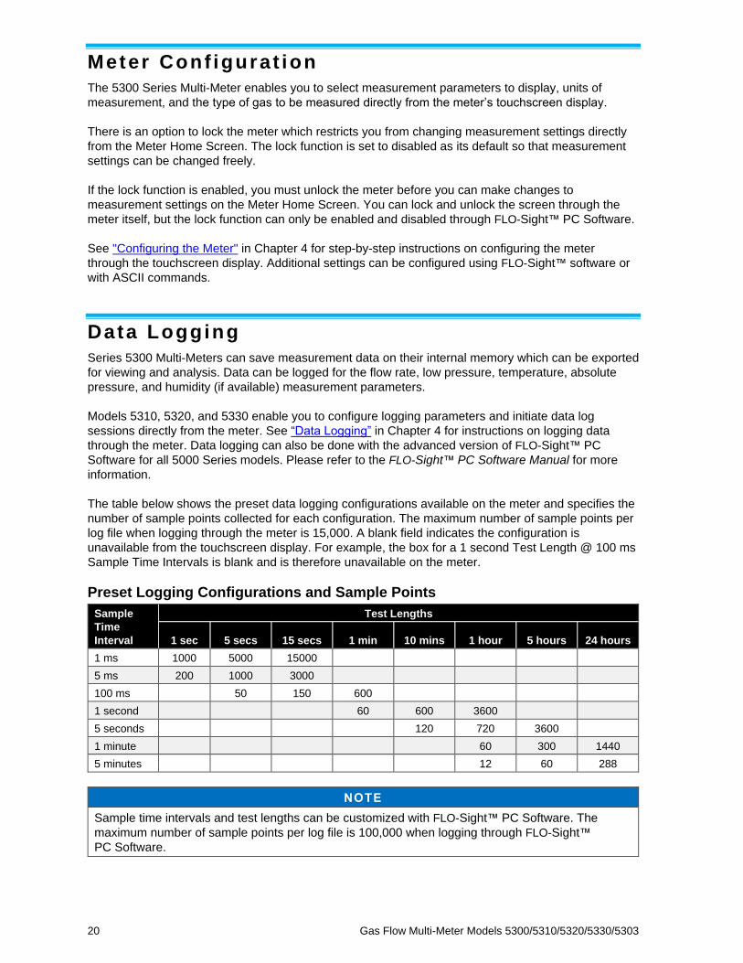
The table below shows the preset data logging configurations available on the meter and specifies the
number of sample points collected for each configuration. The maximum number of sample points per
log file when logging through the meter is 15,000. A blank field indicates the configuration is
unavailable from the touchscreen display. For example, the box for a 1 second Test Length @ 100 ms
Sample Time Intervals is blank and is therefore unavailable on the meter.
Preset Logging Configurations and Sample Points
Sample
Time
Interval
Test Lengths
1 sec 5 secs 15 secs 1 min 10 mins 1 hour 5 hours 24 hours
1 ms 1000 5000 15000
5 ms 200 1000 3000
100 ms 50 150 600
1 second 60 600 3600
5 seconds 120 720 3600
1 minute 60 300 1440
5 minutes 12 60 288
NOTE
Sample time intervals and test lengths can be customized with FLO-Sight™ PC Software. The
maximum number of sample points per log file is 100,000 when logging through FLO-Sight™
PC Software.
21
C H A P T E R 4 Touchscreen Navigat ion
Display Overv iew
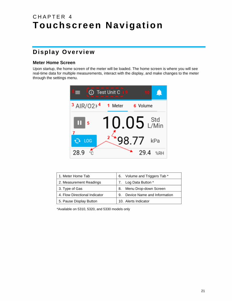
Meter Home Screen
Upon startup, the home screen of the meter will be loaded. The home screen is where you will see
real-time data for multiple measurements, interact with the display, and make changes to the meter
through the settings menu.
1. Meter Home Tab 6. Volume and Triggers Tab *
2. Measurement Readings 7. Log Data Button *
3. Type of Gas 8. Menu Drop-down Screen
4. Flow Directional Indicator 9. Device Name and Information
5. Pause Display Button 10. Alerts Indicator
*Available on 5310, 5320, and 5330 models only
22 Gas Flow Multi-Meter Models 5300/5310/5320/5330/5303
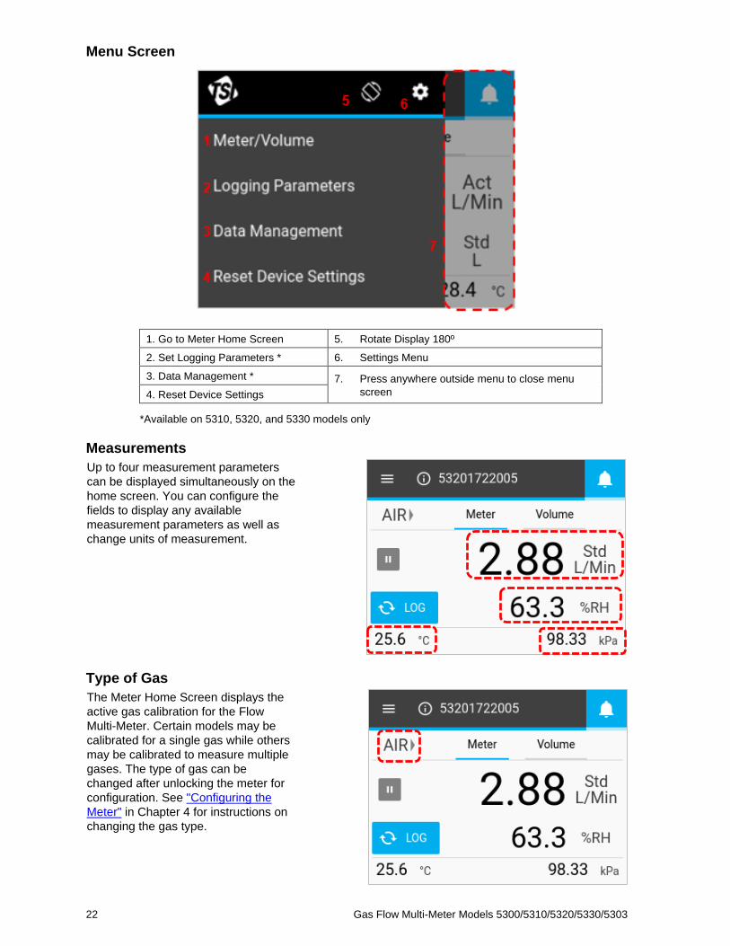
Menu Screen
1. Go to Meter Home Screen 5. Rotate Display 180º
2. Set Logging Parameters * 6. Settings Menu
3. Data Management * 7. Press anywhere outside menu to close menu
screen 4. Reset Device Settings
*Available on 5310, 5320, and 5330 models only
Measurements
Up to four measurement parameters
can be displayed simultaneously on the
home screen. You can configure the
fields to display any available
measurement parameters as well as
change units of measurement.
Type of Gas
The Meter Home Screen displays the
active gas calibration for the Flow
Multi-Meter. Certain models may be
calibrated for a single gas while others
may be calibrated to measure multiple
gases. The type of gas can be
changed after unlocking the meter for
configuration. See "Configuring the
Meter" in Chapter 4 for instructions on
changing the gas type.

23
Flow Directional Indicators
On either side of the “Type of Gas” field, arrows point in the direction of gas flow through the meter and
correspond with changes in the direction of flow. In the default bidirectional mode, flow moving from left
to right → through the meter is shown as positive. Flow moving from right to left through the meter is
shown as negative. If the flow is zero, no indicator arrows will be displayed.
Pause/Play Display
The Pause button is used to pause the display from updating. When the Pause button is pressed, the
current measurement values will remain fixed on the screen. The meter will continue to make
measurements while paused, and pausing the display does not affect any active datalog sessions.
When paused, the button’s icon will change to a green play icon and the display function will become
disabled (grayed out). Press anywhere on the screen to re-enable display functionality. To un-pause
the display and resume screen updates, press the Play button.
24 Gas Flow Multi-Meter Models 5300/5310/5320/5330/5303
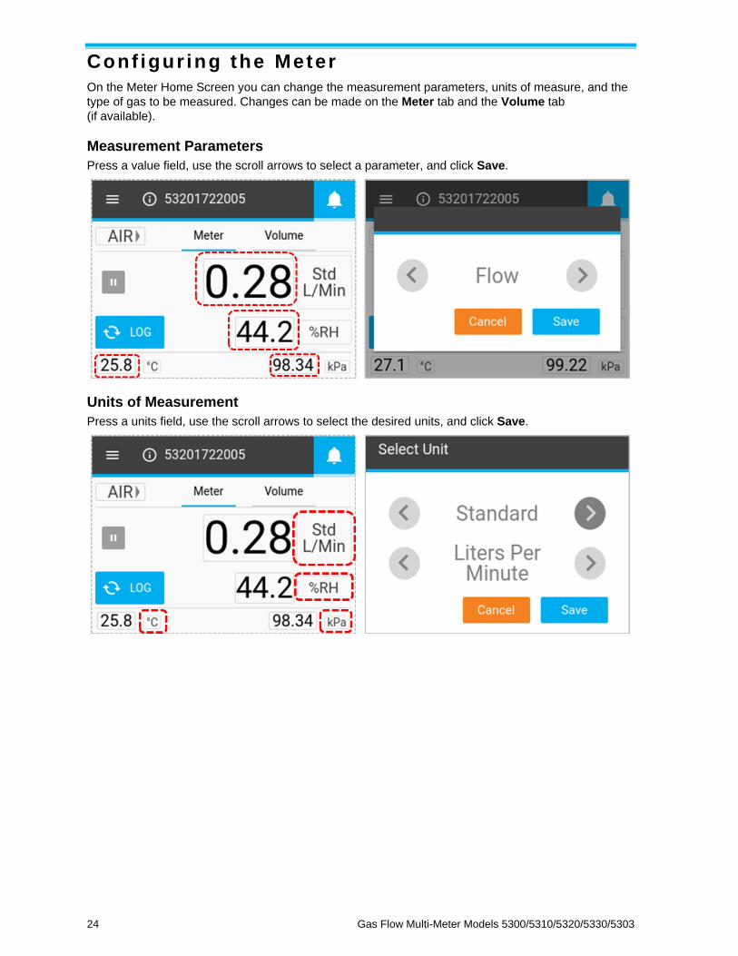
Conf igur ing the Meter
On the Meter Home Screen you can change the measurement parameters, units of measure, and the
type of gas to be measured. Changes can be made on the Meter tab and the Volume tab
(if available).
Measurement Parameters
Press a value field, use the scroll arrows to select a parameter, and click Save.
Units of Measurement
Press a units field, use the scroll arrows to select the desired units, and click Save.

Operation and Service Manual 25
Flow Conditions
When Flow is selected as a measurement parameter, you have the option to select how the flow
measurement is calculated and displayed. These options are available in the Select Unit dialog box
that appears when the Units of Measurement field is pressed for a flow measurement.
Standard This is flow rate the air would be moving if the temperature and pressure were at
standard conditions. For TSI® instruments, standard conditions are defined at 21.1°C
(70°F) and 101.3 kPa (14.7 psia).
Actual This uses the actual temperature and pressure
of the gas to deliver the volumetric flow rate.
This is the true volume flow of the gas exiting
the flow meter.
User This factor allows you to apply your own
temperature and pressure conditions to the
gas flow. You can specify these conditions
with FLO-Sight™ PC Software.
Remote This option allows you to calculate volume flow rate at a remote point in the system
using the absolute pressure and differential pressure measurements. See Appendix D
for more information on Remote Flow Measurements.
Type of Gas
Press the type of gas field, use the scroll arrows to select the type of gas, and click Save.
NOTE
If an Air/Oxygen mix is selected, the meter assigns a 21% oxygen mix. The oxygen concentration
can be customized using FLO-Sight™ PC Software.

26 Gas Flow Multi-Meter Models 5300/5310/5320/5330/5303
Locking the Meter
There is an option to lock the meter which restricts you from changing measurement settings directly
from the Meter Home Screen. With the lock function enabled, you must unlock the meter before you
can make changes to measurement settings on the Meter Home Screen.
You can lock and unlock the screen through the meter itself, but the lock function can only be enabled
and disabled through FLO-Sight™ PC Software. The lock function is set to disabled as its default so
that measurement settings can be changed freely.
Enable Meter Locking
To enable the locking function, connect the
meter to FLO-Sight™ PC Software, click on
the menu icon in the software and select
Settings. Make sure the device you want to
configure is selected, press the Edit button,
click the Device Lock toggle switch, and
press Save. The meter is now locked and
you will not be able to change measurement
parameters, units of measurement, or the
gas type without first unlocking the meter.
Unlock / Lock the Meter
Once the lock function is enabled through FLO-Sight™ PC Software, a lock icon will become visible in
the Menu header of the Flow Multi-Meter. You now must first unlock the meter before you can
configure measurement settings on the Meter Home Screen.
To unlock the meter, select the Menu drop-down on the home screen then select the Lock icon in the
Menu header. Once unlocked, the lock icon will change to an open lock and you can freely change
measurement settings on the Meter Home Screen.
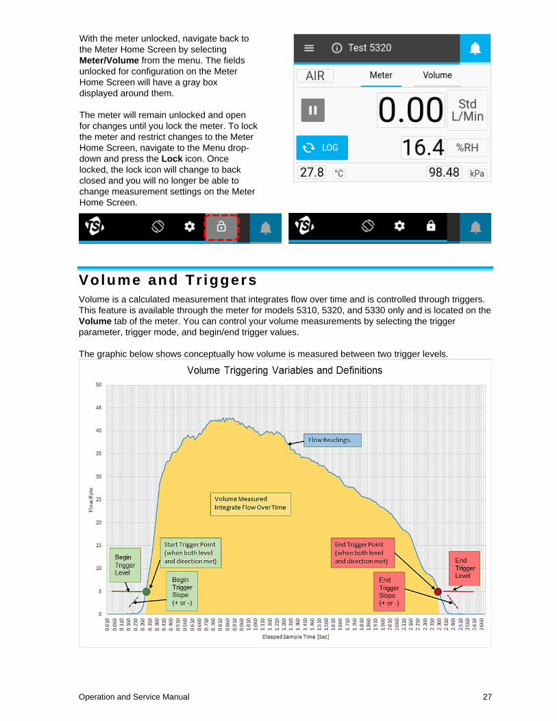
Operation and Service Manual 27
With the meter unlocked, navigate back to
the Meter Home Screen by selecting
Meter/Volume from the menu. The fields
unlocked for configuration on the Meter
Home Screen will have a gray box
displayed around them.
The meter will remain unlocked and open
for changes until you lock the meter. To lock
the meter and restrict changes to the Meter
Home Screen, navigate to the Menu drop-
down and press the Lock icon. Once
locked, the lock icon will change to back
closed and you will no longer be able to
change measurement settings on the Meter
Home Screen.
Volume and Tr iggers
Volume is a calculated measurement that integrates flow over time and is controlled through triggers.
This feature is available through the meter for models 5310, 5320, and 5330 only and is located on the
Volume tab of the meter. You can control your volume measurements by selecting the trigger
parameter, trigger mode, and begin/end trigger values.
The graphic below shows conceptually how volume is measured between two trigger levels.

28 Gas Flow Multi-Meter Models 5300/5310/5320/5330/5303
Setting Triggers
The meter must be stopped to edit trigger settings. On the Volume tab, confirm that the meter is
stopped (shown below left) and press on the field you would like to edit.
If a volume measurement is active (shown below right), then press the Stop button to cancel the
measurement and allow edits to be made to trigger settings.
Select Mode
With the volume screen stopped, press the middle fields to bring up the Select Mode dialog box. In this
screen you can choose your Trigger Parameter (Flow, Absolute Pressure, or Low Differential
Pressure) and Test Mode (Single or Continuous testing). Use the arrows to scroll through the selection
options and click Save to complete.
Trigger Parameter Flow, Absolute Pressure, or Low Pressure
Test Mode Single or Continuous
Single Test Mode: You must press the Play button before each volume measurement is taken.
Continuous Test Mode: The meter will continually make volume measurements each time the begin
trigger condition is met.
Operation and Service Manual 29
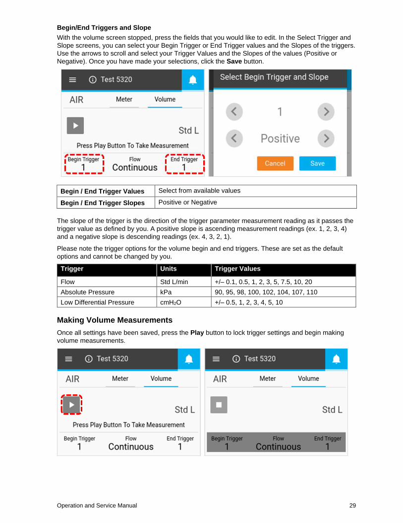
Begin/End Triggers and Slope
With the volume screen stopped, press the fields that you would like to edit. In the Select Trigger and
Slope screens, you can select your Begin Trigger or End Trigger values and the Slopes of the triggers.
Use the arrows to scroll and select your Trigger Values and the Slopes of the values (Positive or
Negative). Once you have made your selections, click the Save button.
Begin / End Trigger Values Select from available values
Begin / End Trigger Slopes Positive or Negative
The slope of the trigger is the direction of the trigger parameter measurement reading as it passes the
trigger value as defined by you. A positive slope is ascending measurement readings (ex. 1, 2, 3, 4)
and a negative slope is descending readings (ex. 4, 3, 2, 1).
Please note the trigger options for the volume begin and end triggers. These are set as the default
options and cannot be changed by you.
Trigger Units Trigger Values
Flow Std L/min +/– 0.1, 0.5, 1, 2, 3, 5, 7.5, 10, 20
Absolute Pressure kPa 90, 95, 98, 100, 102, 104, 107, 110
Low Differential Pressure cmH2O +/– 0.5, 1, 2, 3, 4, 5, 10
Making Volume Measurements
Once all settings have been saved, press the Play button to lock trigger settings and begin making
volume measurements.

30 Gas Flow Multi-Meter Models 5300/5310/5320/5330/5303
Once the Play button is pressed to take measurements, the Flow Multi-Meter will notify you on screen
when the Begin Trigger, and then End Trigger, is reached. After the end trigger is reached, the meter
will display the calculated volume measurement.
Data Logging
Models 5310, 5320, and 5330 enable you to configure logging parameters and initiate data logging
sessions directly from their Flow Multi-Meter. On the Meter Home Screen of these models, a Log
button will be visible. In the Menu drop-down screen, these models will display options for “Logging
Parameters” and “Data Management.”
Logging Parameters
From the Meter Home Screen, press the Menu button and select Logging Parameters from the drop-
down menu. In the Logging Parameters screen, use the scroll arrows to select the Sample Time (aka
sample rate) and Test Length for data logs. The Log Name is automatically generated for each data
file (ex. Log 1, Log 2, Log 3…). Once selections have been made, click on SAVE.
Sample Time
The sample time determines the rate at which the Flow Multi-Meter will store measurement data points.
All data points are the average of 1 ms readings. For example, a 50 ms sample rate would log 20 data
points per second with each data point being comprised of the average of 50 one-millisecond readings.
Operation and Service Manual 31
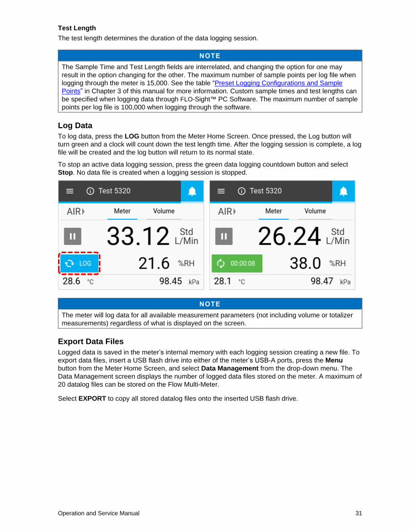
Test Length
The test length determines the duration of the data logging session.
NOTE
The Sample Time and Test Length fields are interrelated, and changing the option for one may
result in the option changing for the other. The maximum number of sample points per log file when
logging through the meter is 15,000. See the table “Preset Logging Configurations and Sample
Points” in Chapter 3 of this manual for more information. Custom sample times and test lengths can
be specified when logging data through FLO-Sight™ PC Software. The maximum number of sample
points per log file is 100,000 when logging through the software.
Log Data
To log data, press the LOG button from the Meter Home Screen. Once pressed, the Log button will
turn green and a clock will count down the test length time. After the logging session is complete, a log
file will be created and the log button will return to its normal state.
To stop an active data logging session, press the green data logging countdown button and select
Stop. No data file is created when a logging session is stopped.
NOTE
The meter will log data for all available measurement parameters (not including volume or totalizer
measurements) regardless of what is displayed on the screen.
Export Data Files
Logged data is saved in the meter’s internal memory with each logging session creating a new file. To
export data files, insert a USB flash drive into either of the meter’s USB-A ports, press the Menu
button from the Meter Home Screen, and select Data Management from the drop-down menu. The
Data Management screen displays the number of logged data files stored on the meter. A maximum of
20 datalog files can be stored on the Flow Multi-Meter.
Select EXPORT to copy all stored datalog files onto the inserted USB flash drive.

32 Gas Flow Multi-Meter Models 5300/5310/5320/5330/5303
Exported data log files are saved in .csv format. Once on the flash drive, you can edit file names,
transfer the files to other devices, or delete the files at your discretion. In addition to measurement
readings, the .csv file (shown below) contains information about the meter, data logging parameters,
and gas conditions.
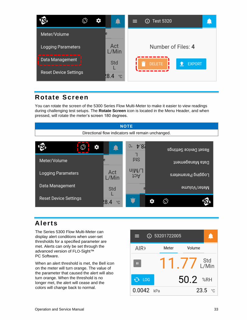
Delete Data Files
To delete logged data files, select Data Management from the Menu drop-down and press the
DELETE button. This will delete all files from the device; individual files cannot be deleted through
the meter.
NOTE
Additional data management functionality is available through FLO-Sight™ PC Software.
Operation and Service Manual 33
Rotate Screen
You can rotate the screen of the 5300 Series Flow Multi-Meter to make it easier to view readings
during challenging test setups. The Rotate Screen icon is located in the Menu Header, and when
pressed, will rotate the meter’s screen 180 degrees.
NOTE
Directional flow indicators will remain unchanged.
Aler ts
The Series 5300 Flow Multi-Meter can
display alert conditions when user-set
thresholds for a specified parameter are
met. Alerts can only be set through the
advanced version of FLO-Sight™
PC Software.
When an alert threshold is met, the Bell icon
on the meter will turn orange. The value of
the parameter that caused the alert will also
turn orange. When the threshold is no
longer met, the alert will cease and the
colors will change back to normal.

34 Gas Flow Multi-Meter Models 5300/5310/5320/5330/5303
Meter In format ion
Pressing the Information icon or Device Name on the Home Screen will display information about
the meter.
Device Name
The name of the device is displayed in the Header Bar on the Home Screen with the text
“TSI 5000 Series” as the default text. The device name can be edited through FLO-Sight™ PC
Software only. Select the DONE button to return to the Home Screen.
Model Number
This field displays the model number of the instrument (ex. 5310). The dash number is the gas
calibration of the meter (ex. -2 above indicates Air/O2 calibration). There will be a letter or number after
the model-dash number that represents the hardware revision (ex. “A” in the above screenshot).
Serial Number
This is the serial number of the meter. The naming convention is as follows: 5XXX YYWW XXX
5XXX = Model Configuration (ex. 5320)
YY = Year of Manufacture
WW = Week of Manufacture
XXX = Manufactured Unit Number
Calibration Date
This is the date that the instrument was last calibrated by TSI®. TSI® recommends an annual
calibration for all flow meters.
IP Address
Each 5300 Series Flow Multi-Meter will have its own unique IP address. The IP address can be used
in establishing communication with a computer and communicating via ASCII commands. Please see
the Series 5200/5300 ASCII Command Set Manual for more information on communicating with
ASCII commands.
Firmware Version
This field displays the current firmware version being used by the Flow Multi-Meter. Firmware updates
can be uploaded through the USB-A port of the meter. The Check for Update button on the Meter
Information screen is used to load firmware updates from an inserted USB drive.

Operation and Service Manual 35
Updating Firmware
TSI® may periodically release firmware updates for the 5000 Series. These update utilities can be
downloaded from www.tsi.com and then installed on the Flow Multi-Meter. Any additional instructions
for downloading files will be available at the time updates are released.
When an update is available, save the file to a USB flash drive and insert the drive into either USB-A
port on the meter. Wait a second after inserting for the meter to recognize the flash drive then select
the CHECK FOR UPDATE button from the Meter Information screen. If an update is located, an
“Update found…” message will appear. Click on the Update button to load the firmware update.
Please allow up to several minutes for the meter to update its firmware. Once complete, an
“Update Successful!” message will display briefly and the meter will automatically reboot. After
reboot the meter will be ready for operation. If the meter does not initialize after the firmware update,
an additional instrument reboot may be necessary.

36 Gas Flow Multi-Meter Models 5300/5310/5320/5330/5303
Device Set t ings
In the Device Settings screen, you can view and edit device settings such as flow control, humidity
compensation, display update rate, and gas standard conditions. Open the Device Settings screen by
navigating to the Menu Screen and pressing the Gear icon in the header bar. The Device Settings
screen is comprised of three tabs: 4040 Mode, Config, and User Gas Std.
4040 Mode
On the “4040 Mode” tab in the Device Settings, you can disable the Bidirectional Flow and Humidity
Compensation features, returning the Flow Multi-Meter to a state similar to the 4000 Series flow
meter. To disable either of these features, select EDIT button and then click on the feature you would
like to disable. The button will slide to the left and become disabled. Press the SAVE button to save
your changes.
Disabling the Bidirectional Flow will result in the Flow Multi-Meter displaying and recording all flows,
regardless of their direction, as positive with a left to right → directional indicator.
Models 5320 and 5330 have the option to disable their Humidity Compensation feature. With humidity
compensation disabled, the 5300 Series will deliver flow readings irrespective of the water vapor
present in the gas flow.

Operation and Service Manual 37
Display Update Rate
The update rate is the rate at which readings are updated on the meter display for all parameters. The
default update rate for the 5300 Series Multi-Meter is 0.5 seconds. To change this setting, select from
a list of options (0.5, 1, 2, 5, or 10 seconds). Note that you can specify a custom display update rate
through FLO-Sight™ PC Software.
To change the update rate, navigate to the Config tab in the Device Settings screen, press the EDIT
button, use the scroll arrows to select a new rate then click SAVE.
Using 0.5 inch or 15-mm Tube Ends
If the 0.5 inch or 15-mm tube ends are connected directly to the instrument, then TSI® recommends
selecting the Tube Ends Toggle Switch in the meter’s Settings screen. The 5300 Series will still
measure within its published accuracy spec even if this recommendation is not followed, but selecting
the toggle switch ensures the most accurate flow measurement readings.
See the section on this topic in Chapter 2 of this manual for more information on when to use the
0.5 inch or 15-mm Tube End toggle switch.
38 Gas Flow Multi-Meter Models 5300/5310/5320/5330/5303
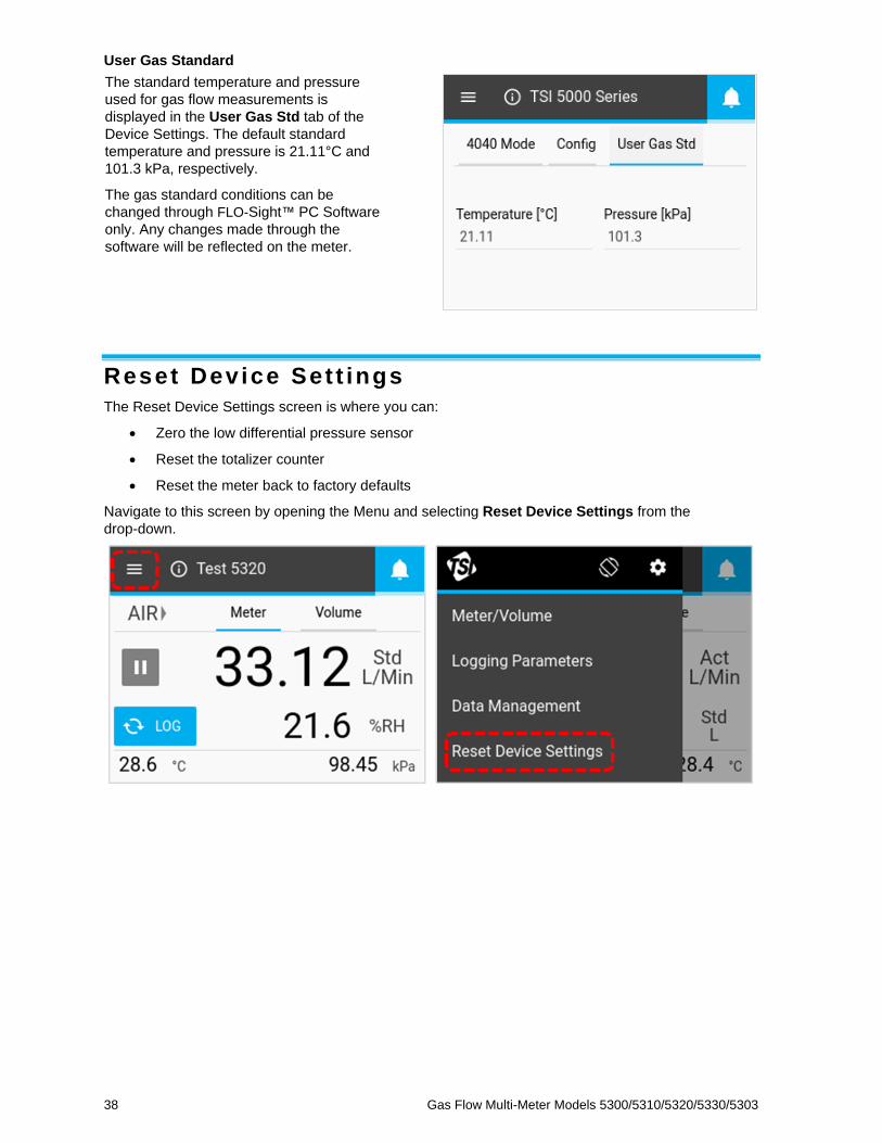
User Gas Standard
The standard temperature and pressure
used for gas flow measurements is
displayed in the User Gas Std tab of the
Device Settings. The default standard
temperature and pressure is 21.11°C and
101.3 kPa, respectively.
The gas standard conditions can be
changed through FLO-Sight™ PC Software
only. Any changes made through the
software will be reflected on the meter.
Reset Dev ice Set t ings
The Reset Device Settings screen is where you can:
• Zero the low differential pressure sensor
• Reset the totalizer counter
• Reset the meter back to factory defaults
Navigate to this screen by opening the Menu and selecting Reset Device Settings from the
drop-down.

Operation and Service Manual 39
Zero Low Pressure
Models 5310, 5320, and 5330 Gas Flow Multi-Meters have an integrated differential pressure sensor.
To zero the differential pressure sensor, click the Zero button, then click the Zero button again in the
Zero Low Pressure dialog box.
Reset Totalizer
All 5300 Series Gas Flow Multi-Meters include a totalizer feature that measures total volume by
integrating flow over time. This is a calculated measurement performed by the meter and operates as
a running total. To reset the Totalizer counter to zero, select the middle RESET button, then click the
Reset button in the Rest Totalizer dialog box.
Reset Device to Factory Defaults
The 5300 Series Gas Flow Multi-Meter can be reset to its factory default settings. See the table below
for details on the settings which will be affected. Resetting the device to factory defaults will not affect
any logged data files stored on the meter. To reset to factory defaults, select the lower RESET button,
then click Reset in the Reset Settings dialog box.

40 Gas Flow Multi-Meter Models 5300/5310/5320/5330/5303
Factory Default Settings
Description Setting Default Condition
Measurement Parameters Flow Std L/min
Temperature oC
Absolute Pressure kPa
Gas Calibration Type of Gas Air (if available)
Gas Standard Conditions Temperature 21.11oC
Absolute Pressure 101.3 kPa
Volume Sampling Stopped Std L
Begin Trigger 1 L, Positive slope
End Trigger 1 L, Negative slope
Flow Mode Flow, Continuous
Logging Parameters Sample Time 1 millisecond
Test Length 15 seconds
Log Name Log 1
Meter Information Device Name “TSI 5000 Series”
Device Settings Bidirectional Flow Enabled
Humidity Compensation Enabled (if available)
Update Rate (Display) 0.5 seconds

41
C H A P T E R 5 Maintenance
Flow Sensor
Periodically inspect the flow sensor by looking into the outlet of the flow meter. Remove dust, particles
and fibers from the sensor, with clean, dry compressed air. The flow sensor will break if touched.
NOTE
NEVER RUN LIQUIDS THROUGH THE FLOW METER AND
NEVER TOUCH THE SENSOR WITH A BRUSH.
Dust or other deposits on the flow sensor will degrade the 5300 Series Multi-Meter’s flow accuracy.
CAUTION
The flow meter must be switched off for cleaning. Only use clean, dry, compressed air when attempting to remove contamination from the sensor.
Re-Cer t i f ica t ion
To maintain a high degree of confidence in the measurements made by the 5300 Series Gas Flow
Multi-Meter, TSI® recommends that the instrument be returned to TSI® every 12 months for
re-certification. For a nominal fee, TSI® will recalibrate the unit and return it to you with an As-Found
and As-Left Certificate of Calibration with US National Institute of Standards Technology (NIST)
traceability. This annual re-certification assures you consistently accurate measurements and is
especially important for applications in which strict calibration records must be maintained.
To send your 5300 Series Gas Flow Multi-Meter back to TSI® for re-certification, please visit TSI®’s
website at www.tsi.com, select Register a repair / calibration under the Support tab, and follow the
instructions. If you are having difficulty completing this process, please contact TSI®’s Customer
Support Group for assistance by calling 800-680-1220 or 651-490-2860.
Damaged Tube End Connect ions
If the tube end connections become damaged, note that the 5300 Series Multi-Meter does not need to
come back to TSI® for repair. The damaged tube end connections can be replaced by ordering the
appropriate connection size. Reference the list of optional accessories in Chapter 1 of this manual for
part number.
Cases
If the instrument case or storage case needs cleaning, wipe it off with a soft cloth dipped in isopropyl
alcohol or mild detergent. Never submerge the Multi-Meter or allow liquids to enter the flow tube.
42 Gas Flow Multi-Meter Models 5300/5310/5320/5330/5303
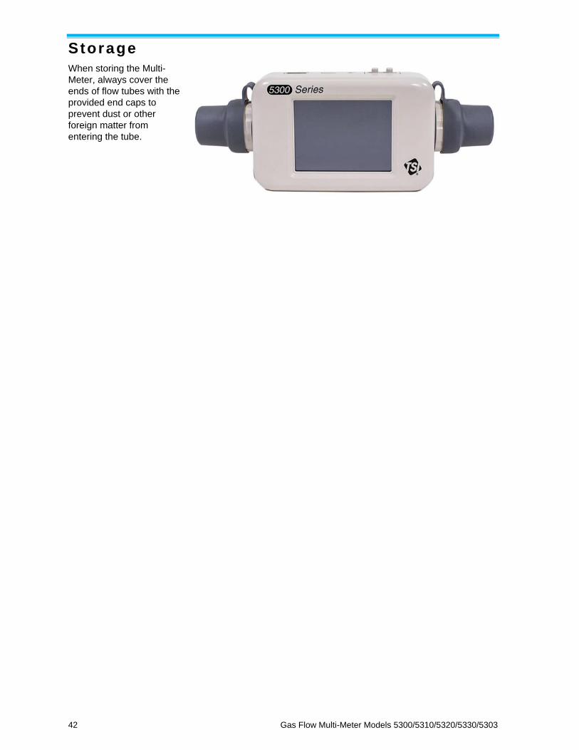
Storage
When storing the Multi-
Meter, always cover the
ends of flow tubes with the
provided end caps to
prevent dust or other
foreign matter from
entering the tube.
Operation and Service Manual 43
C H A P T E R 6 Troubleshoot ing
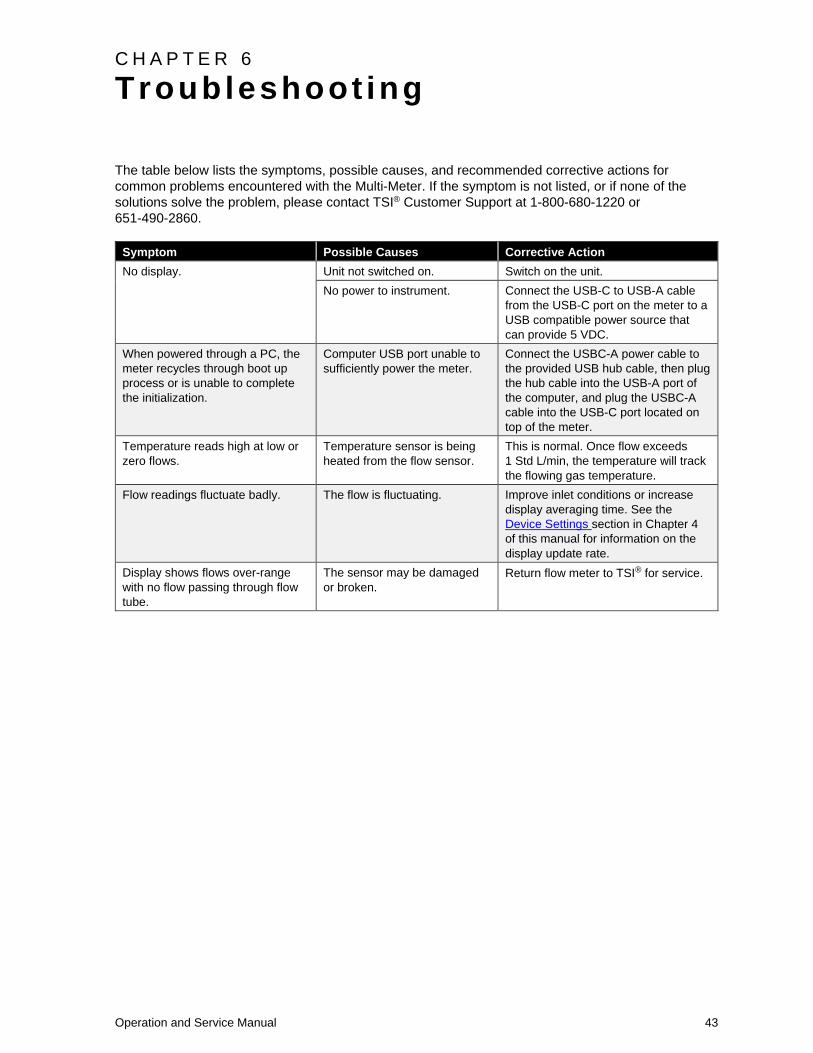
The table below lists the symptoms, possible causes, and recommended corrective actions for
common problems encountered with the Multi-Meter. If the symptom is not listed, or if none of the
solutions solve the problem, please contact TSI® Customer Support at 1-800-680-1220 or
651-490-2860.
Symptom Possible Causes Corrective Action
No display. Unit not switched on. Switch on the unit.
No power to instrument. Connect the USB-C to USB-A cable
from the USB-C port on the meter to a
USB compatible power source that
can provide 5 VDC.
When powered through a PC, the
meter recycles through boot up
process or is unable to complete
the initialization.
Computer USB port unable to
sufficiently power the meter.
Connect the USBC-A power cable to
the provided USB hub cable, then plug
the hub cable into the USB-A port of
the computer, and plug the USBC-A
cable into the USB-C port located on
top of the meter.
Temperature reads high at low or
zero flows.
Temperature sensor is being
heated from the flow sensor.
This is normal. Once flow exceeds
1 Std L/min, the temperature will track
the flowing gas temperature.
Flow readings fluctuate badly. The flow is fluctuating. Improve inlet conditions or increase
display averaging time. See the
Device Settings section in Chapter 4
of this manual for information on the
display update rate.
Display shows flows over-range
with no flow passing through flow
tube.
The sensor may be damaged
or broken.
Return flow meter to TSI® for service.

44 Gas Flow Multi-Meter Models 5300/5310/5320/5330/5303
Technica l Contacts
• If you have technical or application questions about this instrument, contact an applications
engineer at one of the locations listed below.
• If the Gas Flow Multi-Meter fails, or if you are returning it for service, visit our website at
tsi.com/service or contact TSI® at:
TSI Incorporated 500 Cardigan Road Shoreview, MN 55126 USA
Phone: +1-800-680-1220 (USA) or
+1 (651) 490-2860
E-mail: [email protected]
TSI GmbH Neuköllner Strasse 4 52068 Aachen GERMANY
Telephone: +49 241-52303-0 Fax: +49 241-52303-49 E-mail: [email protected]
TSI Instruments Ltd. Stirling Road Cressex Business Park High Wycombe, Bucks HP12 3ST UNITED KINGDOM
Telephone: +44 (0) 149 4 459200 E-mail: [email protected]
TSI Instrument (Beijing) Co., Ltd. Unit 1201, Pan-Pacific Plaza No. 12 A, Zhongguancun South Avenue Haidian District, Beijing, 100181 CHINA
Telephone: +86-10-8219 7688 Fax: +86-10-8219 7699 E-mail: [email protected]
TSI Instruments Singapore Pte Ltd 150 Kampong Ampat #05-05 KA Centre Singapore 368324
Telephone: +65 6595-6388 Fax: +65 6595-6399 E-mail: [email protected]
TSI France Inc. Hotel technologique BP 100 Technopôle de Château-Gombert 13382 Marseille cedex 13 FRANCE
Telephone: +33 (0)1 41 19 21 99 Fax: +33 (0)1 47 86 00 07 E-mail: [email protected]
Returning the Gas F low Mul t i -Meter for Serv ice
Before returning the Gas Flow Multi-Meter to TSI® for service, visit our website at tsi.com/service or
call TSI® at 1-800-680-1220 (USA) or +1 (651) 490-2860 for specific return instructions. Customer
Service will need this information when you call:
• The instrument model number
• The instrument serial number
• A purchase order number (unless under warranty)
• A billing address
• A shipping address.
TSI® recommends that you keep the original packaging (carton and foam inserts) of the Gas Flow
Multi-Meter for use whenever the Gas Flow Multi-Meter is shipped, including when it is returned to
TSI® for service.
Operation and Service Manual 45
C H A P T E R 7 FLO-Sight ™ PC Sof tware
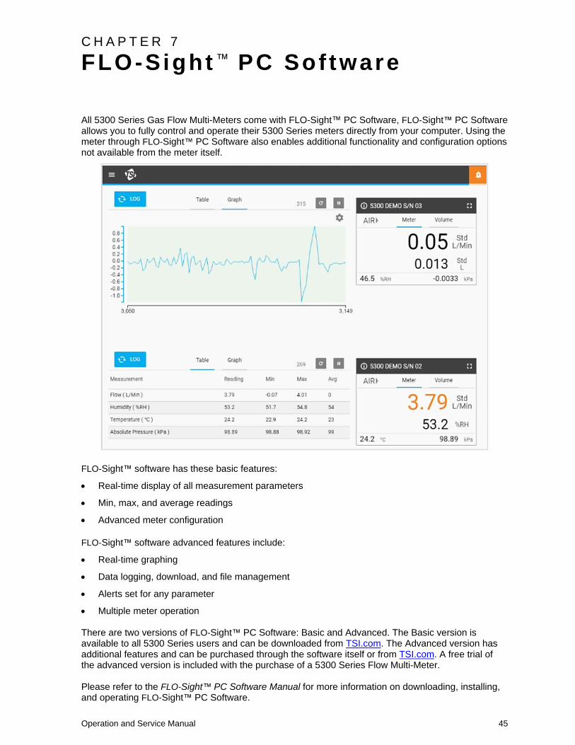
All 5300 Series Gas Flow Multi-Meters come with FLO-Sight™ PC Software, FLO-Sight™ PC Software allows you to fully control and operate their 5300 Series meters directly from your computer. Using the meter through FLO-Sight™ PC Software also enables additional functionality and configuration options not available from the meter itself.
FLO-Sight™ software has these basic features:
• Real-time display of all measurement parameters
• Min, max, and average readings
• Advanced meter configuration
FLO-Sight™ software advanced features include:
• Real-time graphing
• Data logging, download, and file management
• Alerts set for any parameter
• Multiple meter operation There are two versions of FLO-Sight™ PC Software: Basic and Advanced. The Basic version is available to all 5300 Series users and can be downloaded from TSI.com. The Advanced version has additional features and can be purchased through the software itself or from TSI.com. A free trial of the advanced version is included with the purchase of a 5300 Series Flow Multi-Meter. Please refer to the FLO-Sight™ PC Software Manual for more information on downloading, installing, and operating FLO-Sight™ PC Software.

46 Gas Flow Multi-Meter Models 5300/5310/5320/5330/5303
(This page intentionally left blank)

Operation and Service Manual 47
C H A P T E R 8 Ser ia l Command Set
The 5000 Series can establish communication with a computer over either a direct USB link utilizing a
NDIS driver or over RS-232 utilizing a USB to RS-232 converter. Once the meter has been connected,
you can communicate via serial using ASCII commands.
The ASCII commands are case sensitive. Upper case letters are used throughout the command set
except as designated. Each command sent to the flow meter must be terminated by a carriage return
(CR = 0x0d). Line feeds (LF = 0x0a) are ignored.
Listed below is a summary of the commands. For more details, please refer to the 5000 Series ASCII
Command Set Manual.
Commands for F low Rate , Temperature , Pressure , and Volume
Command Description
Backward Compatible
with 4000/4100 Series
DmFTPnnnn Returns flow rate, temperature, and absolute
pressure data at an interval equal to the
sample rate.
Yes
DmFTPHLInnnn Returns flow rate, temperature, absolute
pressure, humidity, low pressure and
totalizer data at an interval equal to the
sample rate.
No
Vmnnnn Returns a volume measurement by
integrating flow rate over time.
Yes
Measurement Setup Commands
Command Description
Backward Compatible
with 4000/4100 Series
SBTxnnn.nn Sets the begin-trigger level for starting data
acquisition.
Yes
SETxnnn.nn Sets the end-trigger level for stopping data
acquisition.
Yes
CBT Clears the begin-trigger level. Yes
CET Clears the end-trigger level. Yes
SSRnnnn Sets the sample rate at which the data is
returned.
Yes
SGn Sets the gas calibration to be used. Yes
SGMmm Selects the air/oxygen mixture concentration. Yes
SUn Selects either standard or volumetric units of
flow.
Yes
SSTnn.nn Sets user standard temperature. Yes
SSPnnn.nn Sets user standard pressure. Yes

48 Gas Flow Multi-Meter Models 5300/5310/5320/5330/5303
Command Description
Backward Compatible
with 4000/4100 Series
SDU2 Sets output flow units to Cubic Feet per
Minute.
Yes
LPZ Low pressure zero. No
SCHx Turn humidity correction off. No
SCDx Turn bi-directional sensor off. No
Miscel laneous Commands
Command Description
Backward Compatible
with 4000/4100 Series
Rxx Reads the current values of the changeable
operating parameters.
Yes
DEFAULT Restores the values of changeable operating
parameters to factory default settings.
Yes
SN Returns the serial number of the flow meter. Yes
MN Returns the model number of the flow meter. Yes
REV Returns the internal firmware revision of the
flow meter.
Yes
HREV Returns the internal hardware revision of the
flow meter.
No
DATE Returns the date of the last calibration. Yes
? Returns “OK” to tell if the flow meter is
communicating.
Yes
SUSTRxxxxxxxx Set user string. Yes
RUSTR Read user string. Yes
SALIASxxxxxx
xxxxxxxxxx
Set meter alias. No
RALIAS Read user string. No
BREAK Stop the current sending of data. No
SBAUDnnnnnn Set RS-232 baud rate. No
RBAUD Read RS-232 baud rate. No
Display Commands
Command Description
Backward Compatible
with 4000/4100 Series
SURnnnn Sets the update rate for the LCD display. Yes

Operation and Service Manual 49
A P P E N D I X A 5300 Ser ies F low Mul t i -Meter Speci f icat ions
Measurement Specifications*
Flow Measurement
Gas Calibrations Air, O2, CO2, N2, (user selectable)
Range 0 to ±300 Std. L/min
0 to ±100 Std L/min (CO2)
Accuracy
See notes 1
through 6 below
Models 5300, 5310, 5320
2% of reading or 0.05 std. L/min, whichever is
greater
Model 5330
1.7% of reading or 0.05 slpm for forward flows, 2%
of reading or 0.05 std. L/min for reverse flows
Model 5303
3% of reading or 0.1 std. L/min, whichever is greater
Response 4 ms to 63% of full scale
Units L/min or ft3/min (Standard, Volumetric, Actual, or
Remote)
Temperature
Measurement
Range -10 to 50°C
Accuracy ±1°C at flows > 1 Std. L/min in the forward direction
Response <= 75 ms to 63% of final value for step change
Units °C, °F
Absolute Pressure
Measurement
Range 50 to 200 kPa
Accuracy ±1 kPa
Response <= 4 ms to 63% of final value for step change
Units Pa, hPa, kPa, mbar, PSI, mmHG, cmH2O, inH2O
Low Differential /
Breathing Circuit
Pressure Measurement
Range ±150 cmH2O
Accuracy ±0.5% of reading or 0.15 cmH2O, whichever is
greater
Response <= 4 ms to 63% of final value for step change
Units Pa, hPa, kPa, mbar, PSI, mmHG, cmH2O, inH2O
Humidity Measurement Range 10-90% RH, -10 oC to +19
oC Dew Point
Accuracy ±3% of reading
Response <= 3 seconds to 63% of final value for step change
Units % RH, Dew Point (oC,
oF)
Volume Measurement Range 0.004 to 99 L
Accuracy 2% of reading or 1 mL whichever is greater, at peak
flows greater than 2.5 std. L/min
See notes 1 through 6 below
Units L, mL, ft3

50 Gas Flow Multi-Meter Models 5300/5310/5320/5330/5303
Measurement Specifications*
Totalizer Measurement Range 0.05 to 400,000 L
Accuracy ±4% of reading
Units L, mL, ft3
Burst Pressure Tested to 690 kPa without rupture. DO NOT exceed 690 kPa.
Pressure Drop See Chart Below
Instrument Temperature
Range
Operation -10 to 50oC (ambient)
Storage -20 to 70oC (ambient)
Instrument Pressure
Range
Operation 50 to 200 kPa
Power Supplied through USB-C port
5.0 VDC ±5%, 500 mA maximum
Digital Output USB, RS-232 Serial using USB to RS-232 converter cable
Display 2.8-inch Color LCD Touchscreen
Internal Storage 1 GB storage, max 20 datalog files
Physical Dimensions External See Diagram Below
Weight 230 grams including protective end caps
Material Polycarbonate (Flow body)
NOTES: 1 Flow accuracy stated between 15 and 25 °C and 101.3 kPa.
• Add an additional 0.085% of reading per 1°C away from the base operating range of 15 to 25 °C.
• Add an additional 0.01% of reading per 1 kPa above 101.3 kPa or
• Add an additional 0.02% of reading per 1 kPa below 101.3 kPa when operating within the pressure range of 70 kPa to 170 kPa.
2 Flow accuracy stated with gas temperature and flow body temperature within ±10°C of one another.
3 Flow accuracy stated measuring dry gas (less than 10% R.H.). Add an additional ±1.0% of reading per 10% of RH away from 0% for models without humidity compensation.
4 Abrupt changes from high to low reverse flow may require additional stabilization time to achieve full accuracy. Please contact TSI® for more information.
5 Includes ±0.5% of reading repeatability.
6 Volumetric flow rate is calculated from the mass flow measurement. Add an additional 0.25% of reading to the flow accuracy to account for the uncertainty in measuring gas temperature and pressure.
*Specifications subject to change without notice.
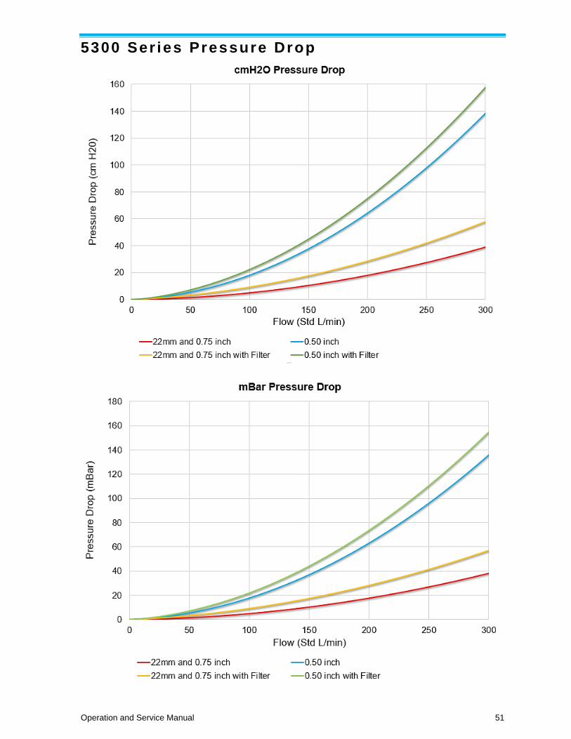
Operation and Service Manual 51
5300 Ser ies Pressure Drop

52 Gas Flow Multi-Meter Models 5300/5310/5320/5330/5303
5300 Ser ies Dimensions
Dimensions are in inches [mm]
Mounting threads: M3

53
A P P E N D I X B S tandard F low Rate vs . Volumetr ic F low Rate
Since thermal flow sensors are sensitive to changes in air density and air velocity, all thermal flow
meters indicate flow rates with reference to a set of standard conditions. For TSI® instruments,
standard conditions are defined as 21.1°C (70°F) and 101.3 kPa (14.7 psia). Other manufacturers may
use different values.
Standard flow rate is the equivalent flow rate the gas would be moving at if the temperature and
pressure were at standard conditions. It is usually the most useful measure of gas flow because it
defines the mass flow, number of molecules, and heat-carrying capacity of the gas.
Volumetric flow rate is the actual volume flow of the gas exiting the Flow Meter.
In some instances, volumetric flow rate rather than standard flow rate may be of interest. To display
the volumetric flow rate, the 5000 Series Multi-Meter will multiply the standard flow measurement by
the following density correction factor:
Volumetric Flow = Q ∗ (Tm
Tstd
) (Pstd
Pm
)
Where:
Q = Standard flow rate
Tm = Gas temperature measured in flow tube in units of degrees Celsius
Pm = Absolute pressure measured in flow tube in units of kPa
TSI® Flow Meters use Tstd = 21.11oC and Pstd = 101.3 kPa absolute
Example:
The mass flow rate measured by the TSI® Multi-Meter is 100 Std. L/min at 15°C and 117 kPa. The
Multi-Meter calculates and displays the volumetric flow as follows.
Volumetric Flow = (100 std L/min) (273.15 + 15°C
273.15 + 21.11°C) (
101.3 kPa
117.0 kPa) = 84.78 L/min

54 Gas Flow Multi-Meter Models 5300/5310/5320/5330/5303
(This page intentionally left blank)

Operation and Service Manual 55
A P P E N D I X C Humidi ty Compensat ion
TSI® models 5320 and 5330 can correct their flow measurement in the presence of moist air. Previous models of TSI® flow meters read up to 5% higher in moist air than in dry air. The change in flow reading was due partly from the added mass of water vapor and partly from the change in thermophysical gas properties introduced by mixing water vapor in air. The 5320 and 5330 model flow meters use a humidity sensor to remove the effect of humidity on the flow measurement. With humidity compensation turned on, the meter will indicate the flow in terms of dry air. In other words, the flow measurement will display the amount of air flow minus the water vapor present.
NOTE
Humidity compensation is only available when measuring the flow of air.
Disable / Enable Humidity Compensation
Users have the option to disable the humidity compensation feature on their Flow Multi-Meter. With humidity compensation disabled, the meter will deliver flow readings irrespective of the water vapor present in the gas flow. The humidity compensation feature is set to enabled as the default.
To disable humidity compensation, select the Gear icon from the Menu header bar. On the 4040 Mode tab, select EDIT, click the Humidity Compensation toggle switch, and SAVE. Select the toggle switch again to enable the feature.
Humidity compensation has also be disabled / enabled through FLO-Sight™ PC Software.

56 Gas Flow Multi-Meter Models 5300/5310/5320/5330/5303
(This page intentionally left blank)

Operation and Service Manual 57
A P P E N D I X D Remote F low
Theory of Operat ion
When combined with absolute pressure, low pressure readings can be used to calculate a volume flow
rate at a remote point in the system. When set to remote flow measurement, the low pressure value is
added to the absolute pressure measured in the channel of the instrument to convert the mass flow of
gas at the instrument to volumetric flow at the remote location. The tubing should be connected from
the positive (+) port on the instrument a tap at the remote location.
NOTE
The remote flow measurement assumes that the gas temperature is consistent between the two
measurement locations. If the gas temperature between the measurement locations is significantly
different, the remote flow measurement will no longer deliver a true reading.
Remote F low Setup
The setup below shows air flowing through two 5000 Series meters in a line. Meter #1 is measuring
upstream of the valve and meter #2 is measuring downstream of the valve. Both meters are
measuring volumetric flow using the actual temperature and pressure of the air flow.

58 Gas Flow Multi-Meter Models 5300/5310/5320/5330/5303
With similar temperature and pressure conditions, the volumetric flow rate between the two
measurement points is consistent.
Meter #1 Meter #2
Back pressure is introduced upstream of the valve. The increased pressure of air being measured by
Meter #1 causes the volumetric flow reading to decrease. Meter #2 does not experience an increase in
pressure and its flow reading remains steady. The remote flow measurement is taken upstream of the
valve and is consistent with the volumetric flow reading from Meter #1 at the same location in the line.
Meter #1 Meter #2

Operation and Service Manual 59
(This page intentionally left blank)

TSI Incorporated – Visit our website www.tsi.com for more information. USA Tel: +1 800 680-1220 UK Tel: +44 149 4 459200 France Tel: +33 1 41 19 21 99 Germany Tel: +49 241 523030
India Tel: +91 80 67877200 China Tel: +86 10 8219 7688 Singapore Tel: +65 6595 6388
P/N 6011689 Rev F ©2021 TSI Incorporated Printed in U.S.A.