Embed Size (px)
Citation preview

Gas Detector Relay: Model 11 and Model 12 Technical Guide
1ZUA5663-211, 22 August 2008

1ZUA5663-211, 22 August 2008 2 / 16
Page 2 of 16
Table of contents 1 Introduction.......................................................................................................3 2 Ordering Information.......................................................................................3 3 Description.........................................................................................................3
3.1 Gas Accumulation Chamber (also known as Alarm Chamber) ..................3 3.2 Pressure Chamber (also known as Trip Chamber)......................................4
4 Installation .........................................................................................................4 5 Operation ...........................................................................................................5
5.1 Gas Accumulation .......................................................................................5 5.2 Gas Sample..................................................................................................5 5.3 Trip ..............................................................................................................6 5.4 Alarm System..............................................................................................6 5.5 Checking Operation.....................................................................................6
6 Gas Detector Relay Characteristic Curve ......................................................7 6.1 Model 11 Characteristic Curve....................................................................7 6.2 Model 12 Characteristic Curve....................................................................7
7 Maintenance ......................................................................................................7 7.1 General Information ....................................................................................7 7.2 Gas Accumulation Mechanism ...................................................................7 7.3 Insulation System ........................................................................................8 7.4 Pressure Mechanism....................................................................................8 7.5 Testing Trip Operation ................................................................................8
8 Characteristic Curves .....................................................................................10 8.1 Characteristic Curve for Model 11 Gas Detector Relay............................10 8.2 Characteristic Curve for Model 12 Gas Detector Relay............................11
9 Figures..............................................................................................................12

Page 3 of 16
1 Introduction
The gas detector relay (GDR) is a protective device that gives an early indication of faults occurring in oil-filled conservator type power transformers. These faults fall into two general classes:
1. Faults of an incipient or minor nature resulting in a slow evolution of gas.This gas may be generated by local heating, defective insulating structures,improperly brazed joints, loose contacts, grounds, short circuit turns, burn-ing of core steel, or from air in the transformer.
2. Faults of a major nature that generates a sudden pressure wave. Majorfaults are usually caused by flashover between parts.
The relay will detect either of these classes of faults.
2 Ordering Information
Description Part Number Length (feet)
Gas Detector Relay, Model 11 1ZUA566002-JAB N/A Gas Detector Relay, Model 12 1ZUA566002-JAA N/A
Cable 1ZUA566002-AAA 4Cable 1ZUA566002-AAB 8Cable 1ZUA566002-AAC 12Cable 1ZUA566002-AAD 16Cable 1ZUA566002-AAE 20Cable 1ZUA566002-AAF 24Cable 1ZUA566002-AAG 28Cable 1ZUA566002-AAH 32Cable 1ZUA566002-AAJ 36Cable 1ZUA566002-AAK 40
3 Description
See a dimensional outline of the Gas Detector Relay in Figure 1 on page 12.
The Gas Detector Relay consists of two sections:
3.1 Gas Accumulation Chamber (also known as Alarm Chamber)
The top half of the Gas Detector Relay is the Gas Accumulation Chamber. It con-sists of a machined, cast aluminum chamber, 3.5 inches (89 mm) magnetic oil level gauge and a gas-sampling valve with flame protective screens.
The magnetic oil level gauge has an internal, normally open contact, which will close when 200 cc of gas has accumulated in the alarm chamber. When this vol-ume occurs, the oil gauge pointer will be in the vertical position.
Any gas, which has accumulated in the alarm chamber, can be extracted through the gas-sampling valve (see section 4.2).
Page 4 of 16
3.2 Pressure Chamber (also known as Trip Chamber)
The lower half of the Gas Detector Relay is the Pressure Chamber. It consists of a machined, cast aluminum chamber, a test-check Schrader valve, a tripping mechanism, pressure activated micro switch, silicone rubber equalizing dia-phragm, inspection cover, ¾-inch NPT pipe tap for oil connection, 4-pin cable connector, and the GDR nameplate.
The trip chamber and alarm chamber are internally connected to allow gas to enter through the 3/4 inch pipe tap and eventually accumulate in the alarm chamber.
The test-check Schrader valve is located at the lower right side of the pressure chamber. See Section 7.5 for further details on its use.
The trip mechanism consists of a sensitive edge-welded bellows, which separates oil-side of the trip mechanism from the airside, a flexible thin metal diaphragm, and micro needle valve, which is factory, calibrated to precisely actuate the trip contact for both the Model 11 and Model 12 relays.
The silicone rubber-equalizing diaphragm is located directly behind the inspection cover. It is designed to seal the trip chamber from external elements and maintain equal pressure between the atmosphere and the internal pressure of the unit, which can vary due to changes in ambient temperature, and pressure.
4 Installation
For the Gas Detector Relay to operate properly, these installation guidelines should be followed:
1. All areas where gas might collect in the transformer should be fitted withfillers or piped to a main gas collection pipe.
2. The cover of the transformer should have a slight dome towards the gaspick up point.
3. The minimum slope on all piping to the Gas Detector Relay should be 2degrees (12 mm per 300 mm or 0.5 inch per foot).
4. The minimum pipe size for gas piping should be 1.0 inch (1.5 inch for coldclimates which have ambient temperatures less than -50°C)
5. Gas collection pipe supports and Gas Detector Relay supports should havea natural frequency greater than 90 Hz.
6. The level of oil in the conservator should not exceed 59 inches (1.5 m)above the top of the relay.
NOTE:
If the head of oil above the relay is greater than 59 inches (1.5 m), the contacts may not reopen after a sudden pressure trip.
NOTE:
Excessive vibration can result in an inadvertent alarm or trip from the relay. On forced oil cooled units, the pump starts can inadvertently trip the relay. It is rec-ommended that time delay relays be used to stager start the pumps when more than one pump is used for cooling. Model 12 is recommended when pumps are involved.
Page 5 of 16
7. Gas Detector Relays should not be placed in the oil pipeline to the conser-vator. Separate piping is recommended for the relay.
8. There should be no obstructions to the flow of gas to the Gas Detector Re-lay. Valves in the gas collection lines must be of a type that will not ob-struct the flow of gas bubbles to the relay. Use of a ball valve is recom-mended.
5 Operation
5.1 Gas Accumulation
The presence of gas in the relay indicates the possibility of a fault in the trans-former. The gas should be released or sampled through the bleeder valve until oil emerges and the time and rate of gas accumulation should be noted. The gas could be coming from a leak in a forced oil system or could be released from the oil itself after the transformer is placed in service. If the gas is flammable, de-composition gases are present and the transformer should be disconnected until the fault has been located and cleared. If the gas is not flammable, the unit should be left in service.
The rate of accumulation of gas is more important than the total volume produced. A record of either (1) time intervals between alarms or (2) alarm chamber pointer positions against time will indicate the degree of urgency of de-energization. A slow, uniform gas accumulation does not indicate immediate need for disconnec-tion. However, accumulation at an accelerating rate does indicate that the trans-former should be de-energized as soon as possible for examination and correction.
5.2 Gas Sample
To take gas and oil samples, proceed as follows:
1. Take syringe sample of the gas from the bleeder valve.
2. Take a sample of oil from the transformer.
3. Have both samples analyzed for types and quantities of gases present.
4. Consult transformer manufacturer for recommendations.
NOTE:
A round, neoprene, sponge cord shipping plug is installed to prevent damage to the bellows during handling and transportation. It is to be removed immediately prior to installation but must be reinstalled if the relay is to be transported sepa-rately or on the transformer.
WARNING: DO NOT TEST FOR GAS FLAMMABILITY WITH AN OPEN FLAME
AT THE BLEEDER VALVE
Page 6 of 16
5.3 Trip
An arc from a major fault within a transformer causes a rapid evolution of gas in the oil, which in turn produces a pressure wave. The pressure wave enters the re-lay through the 3/4 inch (19 mm) pipe tap and compresses the flexible bellows. The air inside the bellows, itself, is compressed. This in turn forces the flexible diaphragm forward. The center of the diaphragm pushes the operating pin of the micro switch causing the trip contacts to change state. Activation of the micro switch can be used to provide a trip signal to other protective equipment.
When a transformer has been tripped by the pressure mechanism of a gas detector relay, the fault that caused the incident should be located and corrected before the unit is re-energized.
Action of a forced oil cooling system may cause a false trip of a relay with a sen-sitive setting. Note that the Model 11 relay is more sensitive than the Model 12. A Model 12 relay may be better suited for transformers with pumped oil.
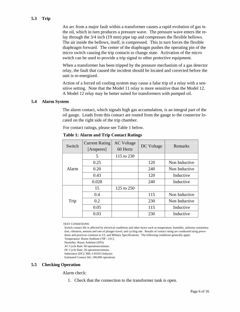
5.4 Alarm System
The alarm contact, which signals high gas accumulation, is an integral part of the oil gauge. Leads from this contact are routed from the gauge to the connector lo-cated on the right side of the trip chamber.
For contact ratings, please see Table 1 below.
Table 1: Alarm and Trip Contact Ratings
Switch Current Rating
[Amperes] AC Voltage
60 Hertz DC Voltage Remarks
5 115 to 230 0.25 120 Non Inductive0.20 240 Non Inductive0.43 120 Inductive
Alarm
0.028 240 Inductive15 125 to 250 0.4 115 Non Inductive0.2 230 Non Inductive0.05 115 Inductive
Trip
0.03 230 Inductive
TEST CONDITIONS Switch contact life is affected by electrical conditions and other factor such as temperature, humidity, airborne contamina-tion, vibration, amount and rate of plunger travel, and cycling rate. Results of contact rating are conducted using proce-dures and practices common to UL and Military Specifications. The following conditions generally apply: Temperature: Room Ambient (70F / 21C) Humidity: Room Ambient (50%) AC Cycle Rate: 60 operations/minute. DC Cycle Rate: 20 operations/minute. Inductance (DC): MIL-I-81023 Inductor. Estimated Contact life: 100,000 operations
5.5 Checking Operation
Alarm check:
1. Check that the connection to the transformer tank is open.

Page 7 of 16
2. Attach and air supply to the test check valve and apply maximum 5 psislowly. The air that displaces the oil will rise to the top of the accumula-tion chamber. As a result, the oil gauge will indicate decreasing oil leveland the presence of air/gas.
3. Remove the air/gas from the relay by opening the gas escape bleeder valvein the manner described under “Gas Accumulation” section of this litera-ture.
Trip check:
1. Check that the connection to the transformer tank is closed.
2. Inject air rapidly. The pressure mechanism should operate indicating a tripsignal. See Section 7.5, “Testing – Trip Operation”.
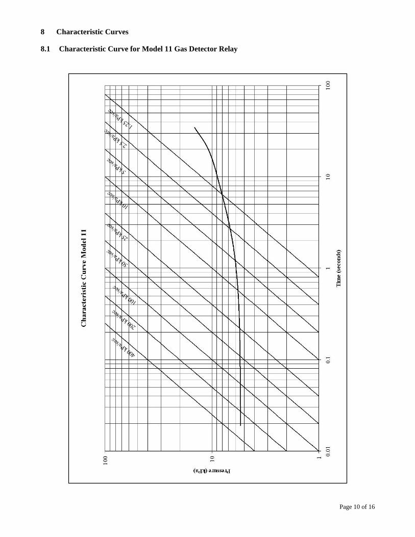
6 Gas Detector Relay Characteristic Curve
The “Characteristic Curve” depicts the results of sensitivity tests made at both high and low rates of pressure rise. The curve shows the time and pressure of which the relay will operate for a wide range of rates of pressure increase. The re-lay will operate at the pressure rise condition above the curve, but will not operate at any pressure rise condition below the curve. Refer to Section 7.1 and 7.2 of this publication.
6.1 Model 11 Characteristic Curve
Please refer to the Model 11 Characteristic Curve in Section 7.1.
Example: A rate of pressure rise of 50 kPa (7.25 psi) per second will operate the relay in 0.12 seconds at 5.45 kPa (0.79 psi).
6.2 Model 12 Characteristic Curve
Please refer to the Model 12 Characteristic Curve in section 7.2.
Example: A rate of pressure rise of 50 kPa (7.25 psi) per second will operate the relay at approximately 0.20 seconds and 10 kPa (2.5 psi).
7 Maintenance
7.1 General Information
NOTE: If a relay fails routine maintenance tests, it should be returned to ABB or an approved service provider for repair. Customers should not attempt to repair the relay since special equipment is needed to re-calibrate to ABB specifications. ABB may not honor any warrantees if the relay has been opened.
Under normal operating conditions, the gas accumulation chamber is filled with oil. As a result, the float remains stationary and the pointer does not move.
7.2 Gas Accumulation Mechanism
Check the gas accumulation mechanism annually by introducing air in the manner
Caution: Do not apply excessie pressure (>5psi) which could
damage the diaphragm and/or the micro switch.
Page 8 of 16
described under “Checking Operation” (Section 5.5). This will cause the pointer to move on its pivot and wipe the interface clean. If the mechanism is inopera-tive, remove the relay and return to ABB for refurbishing.
7.3 Insulation System
Check the insulation system annually by carrying out a Megger test on the relay at 250 volts. Disconnect the wires from the terminal blocks, and Megger the alarm circuit (between black and white), the trip circuit (between red and green) and to ground (black, white, red and green to ground). If a low reading is measured, dis-connect the cable at the relay and check the reading again. If the reading is still low, the problem is likely in the wiring to the relay and not the relay. A low Meg-ger reading in the relay can be an indication of moisture in the relay or contamina-tion on the contacts. The relay should be returned for refurbishing.
7.4 Pressure Mechanism
Check the trip and alarm mechanism the manner described under “Checking Op-eration” (Section 4.5). This is a ‘Go’ — ‘No-Go’ test. If the mechanism does not operate, remove the relay and return it to ABB Inc. for inspection and recalibra-tion.
7.5 Testing
Trip Operation
To test the operation of the relay, a means must be found to apply pressure to the relay test check valve (See Figure 4). With the relay either mounted on the trans-former or on a test bench, this may be done through the test check valve (Schrader valve). A suggested method of test is outlined below.
Close the isolation valve between the transformer and the Gas Detector Relay (or place a pipe plug in the 3/4 NPT diameter pipe tap fitting for oil connection).
Loosen valve element in test check (Schrader) valve by use of the test check-valve cap-wrench. Connect an air supply to the test check valve as shown in Figure 4.
Place the leads from a continuity tester across the red and green leads to determine switch operation.
Apply pressure to trip the relay in approximately two (2) seconds. (See Charac-teristic Curve for the appropriate model GDR).
NOTE THE APPLIED PRESSURE SHOULD NOT EXCEED 5 psi (34 kPa)
Caution: In order to to prevent damage to the sensing mechanism, isolate the Gas Detector Relay from the transformer tank when pres-sure testing or vacuum filling a transformer. If the temperature is likely to change while the Gas Detector Relay is isolated, then open the bleeder to prevent over pressure in the Gas Detector Relay from the thermal expansion or contraction of the oil within the Gas Detector Relay.
Page 9 of 16
Greatly increasing or decreasing the time to reach trip pressure will tend to in-crease the pressure at which the contacts will change state.
Between trip tests on the relay, release any pressure in the relay by venting via the bleeder valve. Also, allow approximately 3 to 5 minutes for the relay to adjust to its initial condition. Experience with each relay will determine the approximate period of time required.
Where the relay is mounted on the transformer, open the valve to the transformer and open the bleeder valve and close it when the oil runs out. Remove air supply, tighten valve element and replace cap of relay test check valve.
It is best to use a pressure gauge as part of the test circuit to guard against apply-ing excessive pressures to the relay. See instructions “Installation and Operation”.
Page 10 of 16
8 Characteristic Curves
8.1 Characteristic Curve for Model 11 Gas Detector Relay

Page 11 of 16
8.2 Characteristic Curve for Model 12 Gas Detector Relay

Page 12 of 16
9 Figures
Figure 1

Page 13 of 16
Figure 2
Page 14 of 16
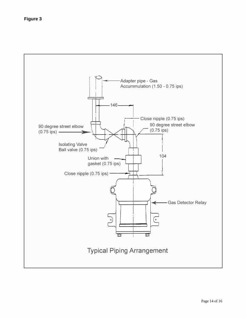
Figure 3

Page 15 of 16
Figure 4

©Copyright 2007 ABB, All rights reserved
Document Title
Gas Detector Relay: Model 11 and Model 12 No. of Pages Page Document No.
1ZUA5663-511 Date & Rev. Ind.
0, 22 August 2008 16 16
Page 16 of 16
DISCLAIMER OF WARRANTIES AND LIMITATION OF LIABILITY THERE ARE NO UNDERSTANDINGS, AGREEMENTS, REPRESENTA-TIONS OR WARRANTIES, EXPRESS OR IMPLIED, INCLUDING WAR-RANTIES OF MERCHANTABILITY OR FITNESS FOR A PARTICULAR PURPOSE OTHER THAN THOSE SPECIFICALLY SET OUT BY AN EX-ISTING CONTRACT BETWEEN THE PARTIES. ANY SUCH CONTRACT STATES THE ENTIRE OBLIGATION OF SELLER. THE CONTENTS OF THIS DOCUMENT SHALL NOT BECOME PART OF OR MODIFYANY PRIOR OR EXISTING AGREEMENT, COMMITMENT OR RELATIONSHIP. The Information, recommendations, description and safety notations in this document are based on our experience and judgment with respect to Bushings. THIS INFORMATION SHOULD NOT BE CONSIDERED TO BE ALL IN-CLUSIVE OR COVERING ALL CONTINGENCIES. If further information is required, ABB Inc. should be consulted. NO WARRANTIES, EXPRESS OR IMPLIED, INCLUDING WARRANTIES OF FITNESS FOR A PARTICULAR PURPOSE OR MERCHANTABILITY, OR WARRANTIES ARISING FROM COURSE OF DEALING OR USAGE OF TRADE, ARE MADE REGARDING THE INFORMATION, RECOM-MENDATIONS, DESCRIPTIONS AND SAFETY NOTATIONS CON-TAINED HEREIN. In no event will ABB Inc. be responsible to the user in contract, in tort (including negligence), strict liability or otherwise for any special, indirect, incidental or consequential damage or loss whatsoever including but not limited to damage to or loss of use of equipment, Plant or power system, cost of capital, loss of profits or revenues, cost of replacement power, additional expenses in the use of exist-ing power facilities, or claims against the user by its customers resulting from the use of the information, recommendations, description and safety notations con-tained herein.