Embed Size (px)
Citation preview
Gas Condensing Wall Hung & Floor Standing Boilers BoschGreenstar & Greenstar FS 100, 151, 131 Combi BoilerGreenstar & Greenstar FS 57, 79, 100, 131, 151 Regular Boiler
WARNING:Improper installation, setup, modifi cation, operation ormaintenance of the heating system can cause personalinjury and property damage.Follow each appliances' instructions precisely.For assistance or further information, contact a trained and certifi ed installer, service provider, or the gas supply company.
Application drawings in this manual are conceptual only and do not purport to address all design, installation, code, or safety considerations.
The diagrams in this manual are for reference use by code offi cials, designers and licensed installers. It is expected that installers have adequate knowledge of national and local codes, as well as accepted industry practices, and are trained on equipment, procedures, and applications involved. Drawings are not to scale.
Refer to the boiler, control and module installer manuals for additional detailed information!
Applications Manual
2 | Bosch Greenstar Applications Manual
Bosch Thermotechnology Corp.Data subject to change
Applications Manual Bosch Greenstar | 3
Bosch Thermotechnology Corp. Data subject to change
Table of Contents
Single Zone Systems 6
System # 1 Greenstar Combi Wall Boiler Single Zone Baseboard with Standard Thermostat (drycontact only) and FW200 (optional) 6
System # 2 Greenstar Combi Wall Boiler Single Zone Baseboard with Bosch CRC control 8
System # 3 Greenstar Combi Floor Boiler Single Zone Baseboard with Standard Thermostat (dry contact only) 10
System # 4 Greenstar Combi Floor Boiler Single Zone Baseboard with Bosch CRC control 12
System # 5 Greenstar Heat only Wall Boiler Single Zone Baseboard with Standard Thermostat (dry contact only) and FW200 (optional) 14
System # 6 Greenstar Heat only Wall Boiler Single Zone Baseboard with Bosch CRC control 16
System # 7 Greenstar Heat only Floor Boiler Single Zone Baseboard with Standard Thermostat (dry contact only) 18
System # 8 Greenstar Heat only Floor Boiler Single Zone Baseboard with Bosch CRC control 20
Multi Zone Systems using Circulators 22
System # 9 Greenstar Combi Wall Boiler Multi zone system using circulators with standard zone relay (FW200 optional) 22
System # 10 Greenstar Combi Wall Boiler Multi zone system using circulators and Bosch Comfort Zone Manager (CZM100) 24
System # 11 Greenstar Combi Floor BoilerMulti zone system using circulators with standard zone relay (FW200 optional) 26
System # 12 Greenstar Combi Floor BoilerMulti zone system using circulators and Bosch Comfort Zone Manager (CZM100) 28
System # 13 Greenstar Heat only Wall BoilerMulti zone system using circulators with standard zone relay (FW200 optional) and indirect tank 30
System # 14 Greenstar Heat only Wall BoilerMulti zone system using circulators and Bosch Comfort Zone Manager (CZM100) and indirect tank 32
System # 15 Greenstar Heat only Floor BoilerMulti zone system using circulators with standard zone relay (FW200 optional) and indirect tank 34
System # 16 Greenstar Heat only Floor BoilerMulti zone system using circulators and Bosch Comfort Zone Manager (CZM100) and indirect tank 36
4 | Bosch Greenstar Applications Manual
Bosch Thermotechnology Corp.Data subject to change
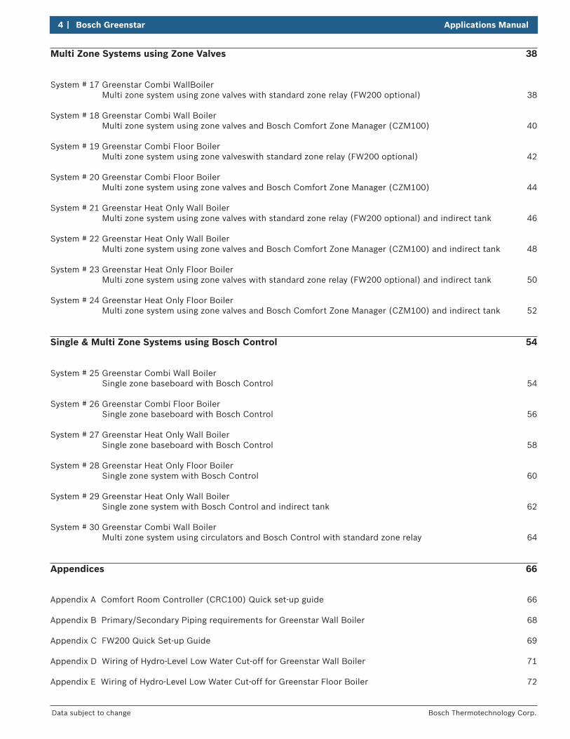
Multi Zone Systems using Zone Valves 38
System # 17 Greenstar Combi WallBoilerMulti zone system using zone valves with standard zone relay (FW200 optional) 38
System # 18 Greenstar Combi Wall BoilerMulti zone system using zone valves and Bosch Comfort Zone Manager (CZM100) 40
System # 19 Greenstar Combi Floor BoilerMulti zone system using zone valveswith standard zone relay (FW200 optional) 42
System # 20 Greenstar Combi Floor BoilerMulti zone system using zone valves and Bosch Comfort Zone Manager (CZM100) 44
System # 21 Greenstar Heat Only Wall BoilerMulti zone system using zone valves with standard zone relay (FW200 optional) and indirect tank 46
System # 22 Greenstar Heat Only Wall BoilerMulti zone system using zone valves and Bosch Comfort Zone Manager (CZM100) and indirect tank 48
System # 23 Greenstar Heat Only Floor BoilerMulti zone system using zone valves with standard zone relay (FW200 optional) and indirect tank 50
System # 24 Greenstar Heat Only Floor BoilerMulti zone system using zone valves and Bosch Comfort Zone Manager (CZM100) and indirect tank 52
Single & Multi Zone Systems using Bosch Control 54
System # 25 Greenstar Combi Wall BoilerSingle zone baseboard with Bosch Control 54
System # 26 Greenstar Combi Floor BoilerSingle zone baseboard with Bosch Control 56
System # 27 Greenstar Heat Only Wall BoilerSingle zone baseboard with Bosch Control 58
System # 28 Greenstar Heat Only Floor BoilerSingle zone system with Bosch Control 60
System # 29 Greenstar Heat Only Wall BoilerSingle zone system with Bosch Control and indirect tank 62
System # 30 Greenstar Combi Wall BoilerMulti zone system using circulators and Bosch Control with standard zone relay 64
Appendices 66
Appendix A Comfort Room Controller (CRC100) Quick set-up guide 66
Appendix B Primary/Secondary Piping requirements for Greenstar Wall Boiler 68
Appendix C FW200 Quick Set-up Guide 69
Appendix D Wiring of Hydro-Level Low Water Cut-off for Greenstar Wall Boiler 71
Appendix E Wiring of Hydro-Level Low Water Cut-off for Greenstar Floor Boiler 72
Applications Manual Bosch Greenstar | 5
Bosch Thermotechnology Corp. Data subject to change
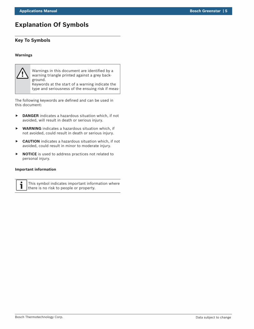
Explanation Of Symbols
Key To Symbols
Warnings
Warnings in this document are identifi ed by a warning triangle printed against a grey back-ground.Keywords at the start of a warning indicate the type and seriousness of the ensuing risk if meas-
The following keywords are defi ned and can be used in this document:
DANGER indicates a hazardous situation which, if not avoided, will result in death or serious injury.
WARNING indicates a hazardous situation which, if not avoided, could result in death or serious injury.
CAUTION indicates a hazardous situation which, if not avoided, could result in minor to moderate injury.
NOTICE is used to address practices not related to personal injury.
Important information
This symbol indicates important information wherethere is no risk to people or property.
6 | Bosch Greenstar Applications Manual
Bosch Thermotechnology Corp.Data subject to change
Bosch
State
Bases
No.
.
Changed
Released
Created
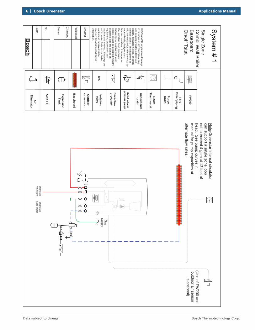
Baseboard
Expansion Tank
Auto-Fill
Air
Eliminator
Isolation valve
Back-flow
preventer
Relief valve &
pressure gauge
Condensate
drain
Outdoor
air sensor
Room
Therm
ostat
(Use of FW
200 and outdoor air sensor
is optional)
Note:G
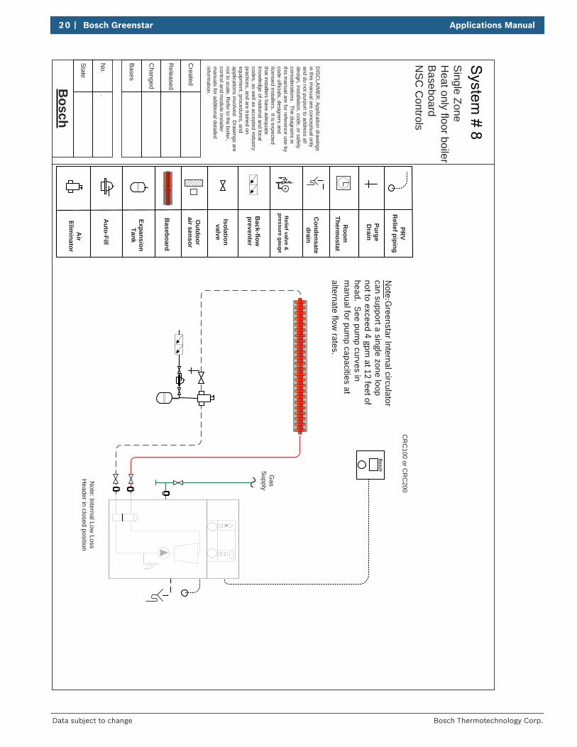
reenstar Internal circulator can support a single zone loop not to exceed 4 gpm
at 12 feet of head. S
ee pump curves in
manual for pum
p capacities at alternate flow
rates.
PurgeD
rain
DIS
CLA
IME
R: A
pplication drawings
in this manual are conceptual only
and do not purport to address all design, installation, code, or safety considerations. The diagram
s in this m
anual are for reference use by code officials, designers and licensed installers. It is expected that installers have adequate know
ledge of national and local codes, as w
ell as accepted industry practices, and are trained on equipm
ent, procedures, and applications involved. D
rawings are
not to scale. Refer to the boiler,
control and module installer
manuals for additional detailed
information.
Dom
esticC
old Water
Dom
esticH
ot Water
Gas
Supply
PRV
Relief piping
FW200
Single Zone
Com
bi Wall B
oilerB
aseboardO
n/off Tstat
Applications Manual Bosch Greenstar | 7
Bosch Thermotechnology Corp. Data subject to change
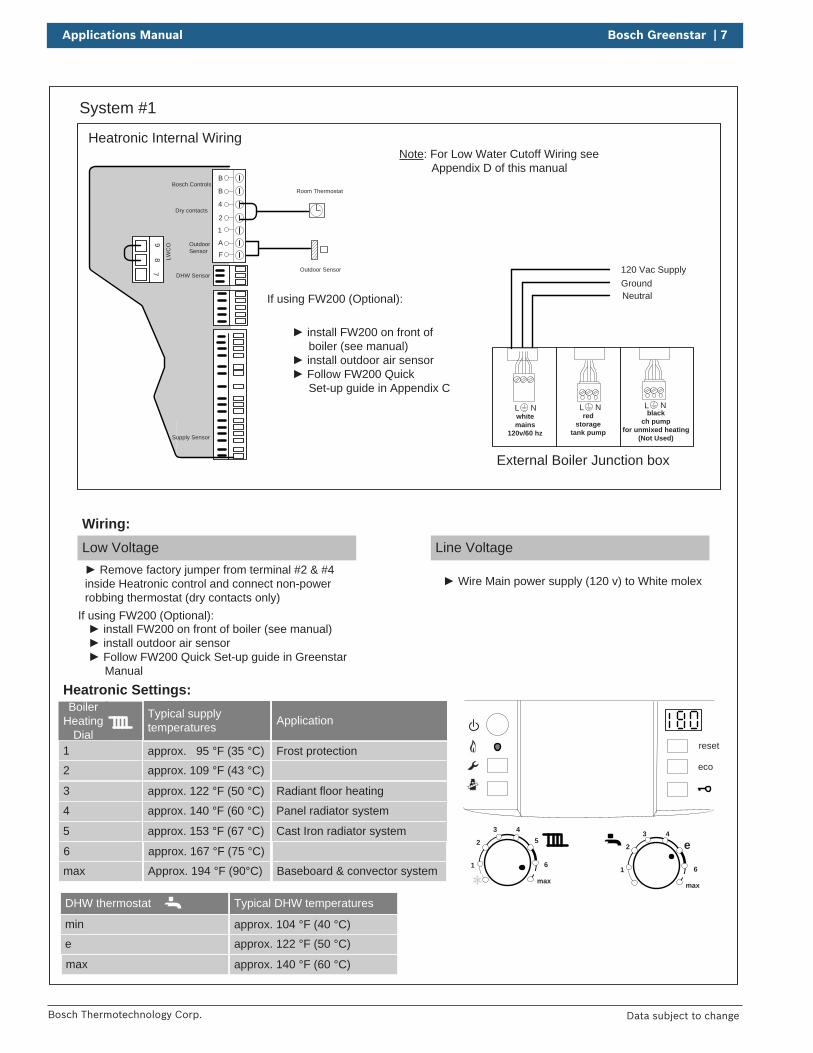
System #1
reset
eco
1
2
3 45
6
max1
2
3 4
e
6
max
DHW thermostat
min
e
max
Typical DHW temperatures
approx. 104 °F (40 °C)
approx. 122 °F (50 °C)
approx. 140 °F (60 °C)
Boiler Heating
Dial1
2
3
Typical supply temperatures
approx. 95 °F (35 °C)
approx. 109 °F (43 °C)
approx. 122 °F (50 °C)
4
5
6
approx. 140 °F (60 °C)
approx. 153 °F (67 °C)
approx. 167 °F (75 °C)
max Approx. 194 °F (90°C)
Application
Frost protection
Radiant floor heating
Panel radiator system
Cast Iron radiator system
Baseboard & convector system
Room Thermostat
Low Voltage
Wiring:Line Voltage
Wire Main power supply (120 v) to White molex
install FW200 on front of boiler (see manual) install outdoor air sensor Follow FW200 Quick Set-up guide in Greenstar
Manual
If using FW200 (Optional):
Heatronic Settings:
Remove factory jumper from terminal #2 & #4 inside Heatronic control and connect non-power robbing thermostat (dry contacts only)
Outdoor Sensor
install FW200 on front of boiler (see manual)
install outdoor air sensor Follow FW200 Quick
Set-up guide in Appendix C
If using FW200 (Optional):
Heatronic Internal Wiring
B
B
4
2
1
A
F
97
8 LWC
O
Supply Sensor
DHW Sensor
Dry contacts
Bosch Controls
Outdoor Sensor
L Nred
storagetank pump
L Nblack
ch pump for unmixed heating
(Not Used)
L Nwhitemains
120v/60 hz
External Boiler Junction box
120 Vac SupplyGroundNeutral
Note: For Low Water Cutoff Wiring see Appendix D of this manual
8 | Bosch Greenstar Applications Manual
Bosch Thermotechnology Corp.Data subject to change
Bosch
State
Bases
No.
.
Changed
Released
Created
TK02/20/15
Baseboard
Expansion Tank
Auto-Fill
Air
Eliminator
Isolation valve
Back-flow
preventer
Relief valve &
pressure gauge
Condensate
drain
Outdoor
air sensor
Com
fort R
oom
Controller
PurgeD
rain
DIS
CLA
IME
R: A
pplication drawings
in this manual are conceptual only
and do not purport to address all design, installation, code, or safety considerations. The diagram
s in this m
anual are for reference use by code officials, designers and licensed installers. It is expected that installers have adequate know
ledge of national and local codes, as w
ell as accepted industry practices, and are trained on equipm
ent, procedures, and applications involved. D
rawings are
not to scale. Refer to the boiler,
control and module installer
manuals for additional detailed
information.
Dom
esticC
old Water
Dom
esticH
ot Water
Gas
Supply
PRV
Relief piping
Bosch
Bosch
CR
C100 or
CR
C200
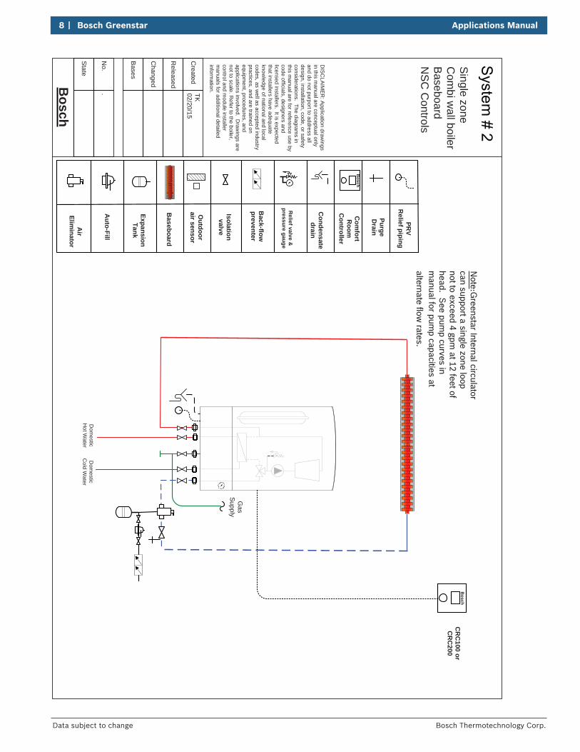
Single zone
Com
bi wall boiler
Baseboard
NS
C C
ontrols
Note:G
reenstar Internal circulator can support a single zone loop not to exceed 4 gpm
at 12 feet of head. S
ee pump curves in
manual for pum
p capacities at alternate flow
rates.
Applications Manual Bosch Greenstar | 9
Bosch Thermotechnology Corp. Data subject to change
System #2
reset
eco
1
2
3 45
6
max1
2
3 4
e
6
max
DHW thermostat
min
e
max
Typical DHW temperatures
approx. 104 °F (40 °C)
approx. 122 °F (50 °C)
approx. 140 °F (60 °C)
Boiler Heating
Dial1
2
3
Typical supply temperatures
approx. 95 °F (35 °C)approx. 109 °F (43 °C)
approx. 122 °F (50 °C)
4
5
6
approx. 140 °F (60 °C)
approx. 153 °F (67 °C)
approx. 167 °F (75 °C)
max Approx. 194 °F (90°C)
Application
Frost protection
Radiant floor heating
Panel radiator system
Cast Iron radiator system
Baseboard & convector system
CRC100 or CRC200
Bosch
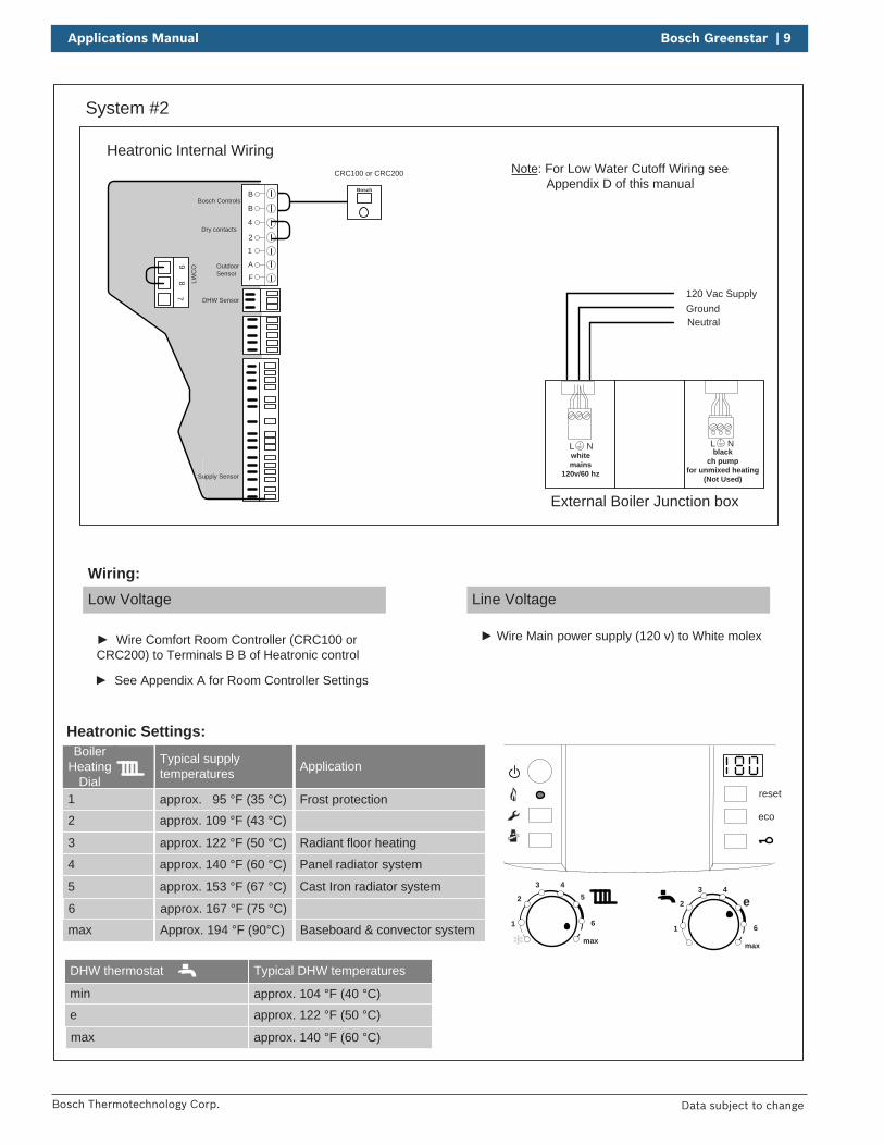
Low Voltage
Wiring:Line Voltage
Wire Comfort Room Controller (CRC100 or CRC200) to Terminals B B of Heatronic control
Wire Main power supply (120 v) to White molex
See Appendix A for Room Controller Settings
Heatronic Settings:
Heatronic Internal Wiring
B
B
4
2
1
A
F
97
8 LWC
O
Supply Sensor
DHW Sensor
Dry contacts
Bosch Controls
Outdoor Sensor
External Boiler Junction box
120 Vac SupplyGroundNeutral
L Nblack
ch pump for unmixed heating
(Not Used)
L Nwhitemains
120v/60 hz
Note: For Low Water Cutoff Wiring see Appendix D of this manual
10 | Bosch Greenstar Applications Manual
Bosch Thermotechnology Corp.Data subject to change
Bosch
State
Bases
No.
.
Changed
Released
Created
Baseboard
Expansion Tank
Auto-Fill
Air
Eliminator
Isolation valve
Back-flow
preventer
Relief valve &
pressure gauge
Condensate
drain
Outdoor
air sensor
Room
Therm
ostat
PurgeD
rain
DIS
CLA
IME
R: A
pplication drawings
in this manual are conceptual only
and do not purport to address all design, installation, code, or safety considerations. The diagram
s in this m
anual are for reference use by code officials, designers and licensed installers. It is expected that installers have adequate know
ledge of national and local codes, as w
ell as accepted industry practices, and are trained on equipm
ent, procedures, and applications involved. D
rawings are
not to scale. Refer to the boiler,
control and module installer
manuals for additional detailed
information.
Dom
esticC
old Water
Dom
esticH
ot Water
Gas
Supply
PRV
Relief piping
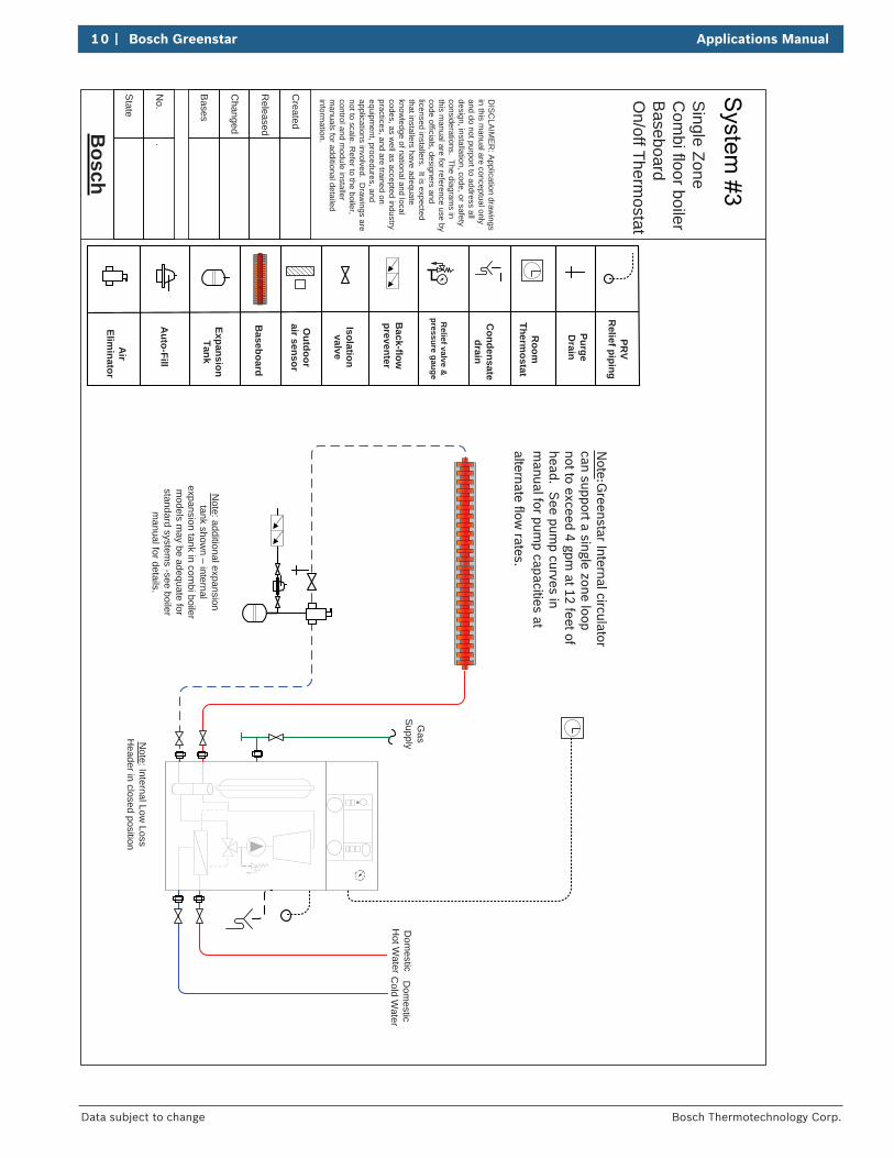
Note: Internal Low
Loss H
eader in closed position
Note: additional expansion tank show
n – internal expansion tank in com
bi boiler m
odels may be adequate for
standard systems -see boiler
manual for details.
Note:G
reenstar Internal circulator can support a single zone loop not to exceed 4 gpm
at 12 feet of head. S
ee pump curves in
manual for pum
p capacities at alternate flow
rates.
Single Zone
Com
bi floor boilerB
aseboardO
n/off Thermostat
Applications Manual Bosch Greenstar | 11
Bosch Thermotechnology Corp. Data subject to change
System #3
Room Thermostat
BUS TT out sen LWCO DHW sen
1 2 3 4 5 6
reset
eco
1
2
3 45
6
max1
2
3 4
e
6
max
DHW thermostat
min
e
max
Typical DHW temperatures
approx. 104 °F (40 °C)
approx. 122 °F (50 °C)
approx. 140 °F (60 °C)
Boiler Heating
Dial1
2
3
Typical supply temperatures
approx. 95 °F (35 °C)
approx. 109 °F (43 °C)
approx. 122 °F (50 °C)
4
5
6
approx. 140 °F (60 °C)
approx. 153 °F (67 °C)
approx. 167 °F (75 °C)
max Approx. 194 °F (90°C)
Application
Frost protection
Radiant floor heating
Panel radiator system
Cast Iron radiator system
Baseboard & convector system
Neutral
120 V Line
Ground
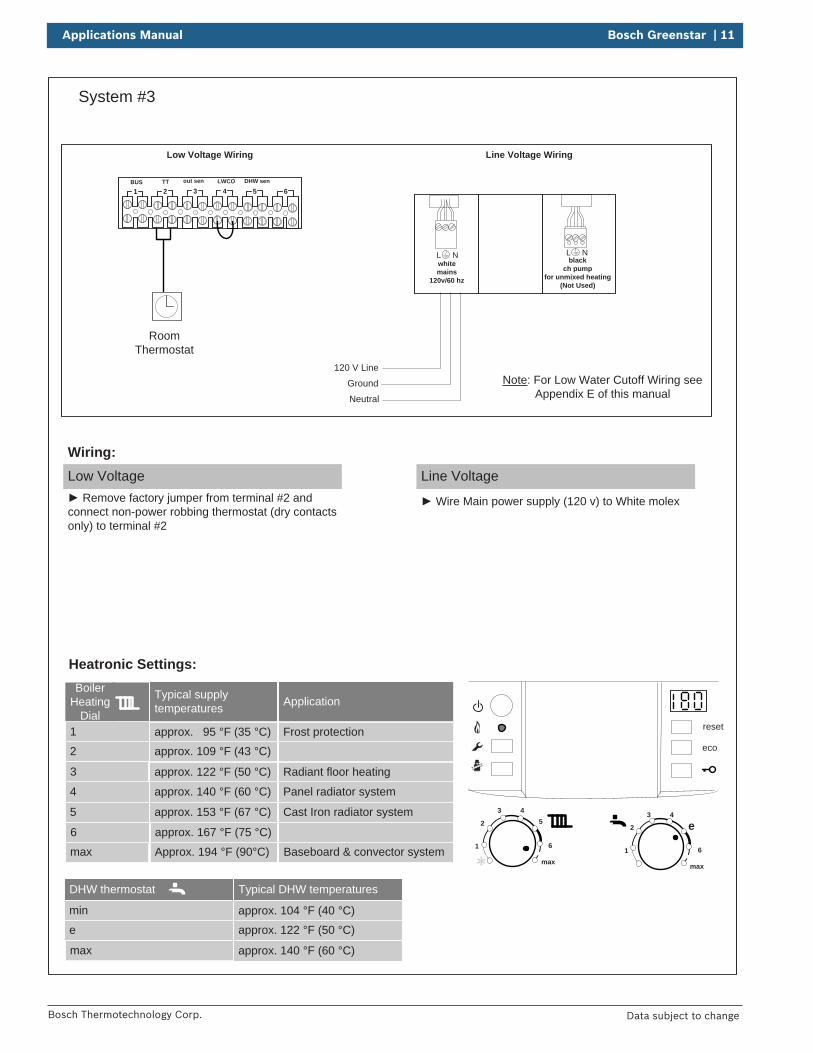
Low Voltage Wiring Line Voltage Wiring
Heatronic Settings:
Low Voltage Remove factory jumper from terminal #2 and
connect non-power robbing thermostat (dry contacts only) to terminal #2
Wiring:Line Voltage
Wire Main power supply (120 v) to White molex
L Nblack
ch pump for unmixed heating
(Not Used)
L Nwhitemains
120v/60 hz
Note: For Low Water Cutoff Wiring see Appendix E of this manual
12 | Bosch Greenstar Applications Manual
Bosch Thermotechnology Corp.Data subject to change
Bosch
State
Bases
No.
.
Changed
Released
Created
Baseboard
Expansion Tank
Auto-Fill
Air
Eliminator
Isolation valve
Back-flow
preventer
Relief valve &
pressure gauge
Condensate
drain
Com
fortR
oomC
ontroller
SupplySensor
PurgeD
rain
DIS
CLA
IME
R: A
pplication drawings
in this manual are conceptual only
and do not purport to address all design, installation, code, or safety considerations. The diagram
s in this m
anual are for reference use by code officials, designers and licensed installers. It is expected that installers have adequate know
ledge of national and local codes, as w
ell as accepted industry practices, and are trained on equipm
ent, procedures, and applications involved. D
rawings are
not to scale. Refer to the boiler,
control and module installer
manuals for additional detailed
information.
Dom
esticC
old Water
Dom
esticH
ot Water
Gas
Supply
PRV
Relief piping
Bosch
Bosch
CR
C100 or C
RC
200
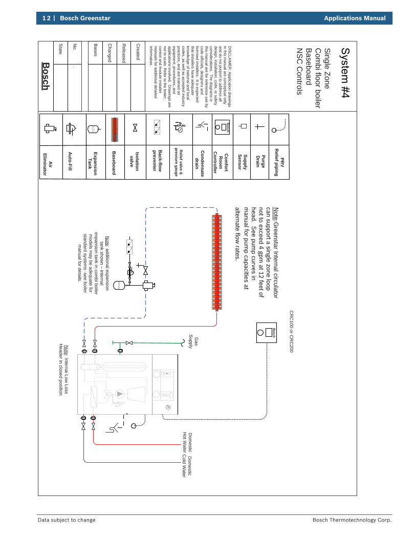
Note : Internal Low
Loss H
eader in closed position
Note: additional expansion tank show
n – internal expansion tank in com
bi boiler m
odels may be adequate for
standard systems -see boiler
manual for details.
Note:G
reenstar Internal circulator can support a single zone loop not to exceed 4 gpm
at 12 feet of head. S
ee pump curves in
manual for pum
p capacities at alternate flow
rates.
Single Zone
Com
bi floor boilerB
aseboardN
SC
Controls
Applications Manual Bosch Greenstar | 13
Bosch Thermotechnology Corp. Data subject to change
System #4
BUS TT out sen LWCO DHW sen
1 2 3 4 5 6
reset
eco
1
2
3 45
6
max1
2
3 4
e
6
max
DHW thermostat
min
e
max
Typical DHW temperatures
approx. 104 °F (40 °C)
approx. 122 °F (50 °C)
approx. 140 °F (60 °C)
Boiler Heating
Dial
1
2
3
Typical supply temperatures
approx. 95 °F (35 °C)
approx. 109 °F (43 °C)
approx. 122 °F (50 °C)
4
5
6
approx. 140 °F (60 °C)
approx. 153 °F (67 °C)
approx. 167 °F (75 °C)
max Approx. 194 °F (90°C)
Application
Frost protection
Radiant floor heating
Panel radiator system
Cast Iron radiator system
Baseboard & convector system
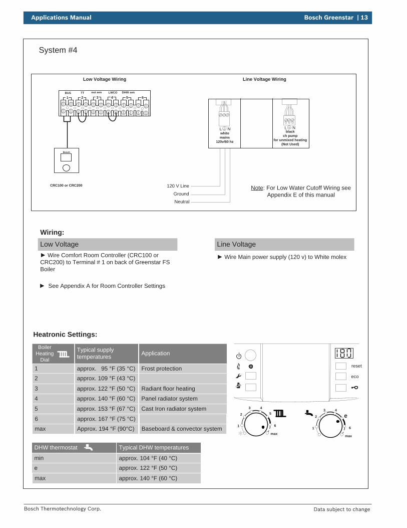
Neutral
120 V Line
Ground
Low Voltage Wiring Line Voltage Wiring
Bosch
CRC100 or CRC200
Heatronic Settings:
Low Voltage Wire Comfort Room Controller (CRC100 or
CRC200) to Terminal # 1 on back of Greenstar FS Boiler
Wiring:Line Voltage
Wire Main power supply (120 v) to White molex
See Appendix A for Room Controller Settings
L Nblack
ch pump for unmixed heating
(Not Used)
L Nwhitemains
120v/60 hz
Note: For Low Water Cutoff Wiring see Appendix E of this manual
14 | Bosch Greenstar Applications Manual
Bosch Thermotechnology Corp.Data subject to change
Bosch
State
Bases
No.
.
Changed
Released
Created
TK02/20/15
Baseboard
Expansion Tank
Auto-Fill
Air
Eliminator
Isolation valve
Back-flow
preventer
Relief valve &
pressure gauge
Condensate
drain
Outdoor
air sensor
Room
Therm
ostat
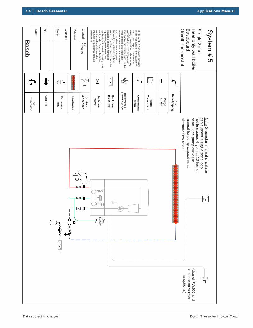
(Use of FW
200 and outdoor air sensor
is optional)
PurgeD
rain
DIS
CLA
IME
R: A
pplication drawings
in this manual are conceptual only
and do not purport to address all design, installation, code, or safety considerations. The diagram
s in this m
anual are for reference use by code officials, designers and licensed installers. It is expected that installers have adequate know
ledge of national and local codes, as w
ell as accepted industry practices, and are trained on equipm
ent, procedures, and applications involved. D
rawings are
not to scale. Refer to the boiler,
control and module installer
manuals for additional detailed
information.
Gas
Supply
PRV
Relief piping
Note:G
reenstar Internal circulator can support a single zone loop not to exceed 4 gpm
at 12 feet of head. S
ee pump curves in
manual for pum
p capacities at alternate flow
rates.
Single Zone
Heat only w
all boilerB
aseboardO
n/off Thermostat
Applications Manual Bosch Greenstar | 15
Bosch Thermotechnology Corp. Data subject to change
System #5
reset
eco
1
2
3 45
6
max1
2
3 4
e
6
max
Boiler Heating
Dial1
2
3
Typical supply temperatures
approx. 95 °F (35 °C)approx. 109 °F (43 °C)
approx. 122 °F (50 °C)
4
5
6
approx. 140 °F (60 °C)
approx. 153 °F (67 °C)
approx. 167 °F (75 °C)
max Approx. 194 °F (90°C)
Application
Frost protection
Radiant floor heating
Panel radiator system
Cast Iron radiator system
Baseboard & convector system
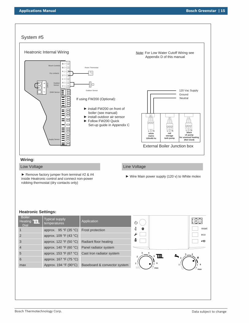
Low Voltage
Wiring:Line Voltage
Wire Main power supply (120 v) to White molex Remove factory jumper from terminal #2 & #4 inside Heatronic control and connect non-power robbing thermostat (dry contacts only)
Heatronic Settings:
Room Thermostat
Outdoor Sensor
install FW200 on front of boiler (see manual)
install outdoor air sensor Follow FW200 Quick
Set-up guide in Appendix C
If using FW200 (Optional):
Heatronic Internal Wiring
B
B
4
2
1
A
F
97
8 LWC
O
Supply Sensor
DHW Sensor
Dry contacts
Bosch Controls
Outdoor Sensor
External Boiler Junction box
120 Vac SupplyGroundNeutral
L Nred
storagetank pump
L Nblack
ch pump for unmixed heating
(Not Used)
L Nwhitemains
120v/60 hz
Note: For Low Water Cutoff Wiring see Appendix D of this manual
16 | Bosch Greenstar Applications Manual
Bosch Thermotechnology Corp.Data subject to change
Bosch
State
Bases
No.
.
Changed
Released
Created
TK02/20/15
Baseboard
Expansion Tank
Auto-Fill
Air
Eliminator
Isolation valve
Back-flow
preventer
Relief valve &
pressure gauge
Condensate
drain
Outdoor
air sensor
Com
fort R
oomC
ontrol
PurgeD
rain
DIS
CLA
IME
R: A
pplication drawings
in this manual are conceptual only
and do not purport to address all design, installation, code, or safety considerations. The diagram
s in this m
anual are for reference use by code officials, designers and licensed installers. It is expected that installers have adequate know
ledge of national and local codes, as w
ell as accepted industry practices, and are trained on equipm
ent, procedures, and applications involved. D
rawings are
not to scale. Refer to the boiler,
control and module installer
manuals for additional detailed
information.
Gas
Supply
PRV
Relief piping
Bosch
CR
C100 or
CR
C200
Bosch
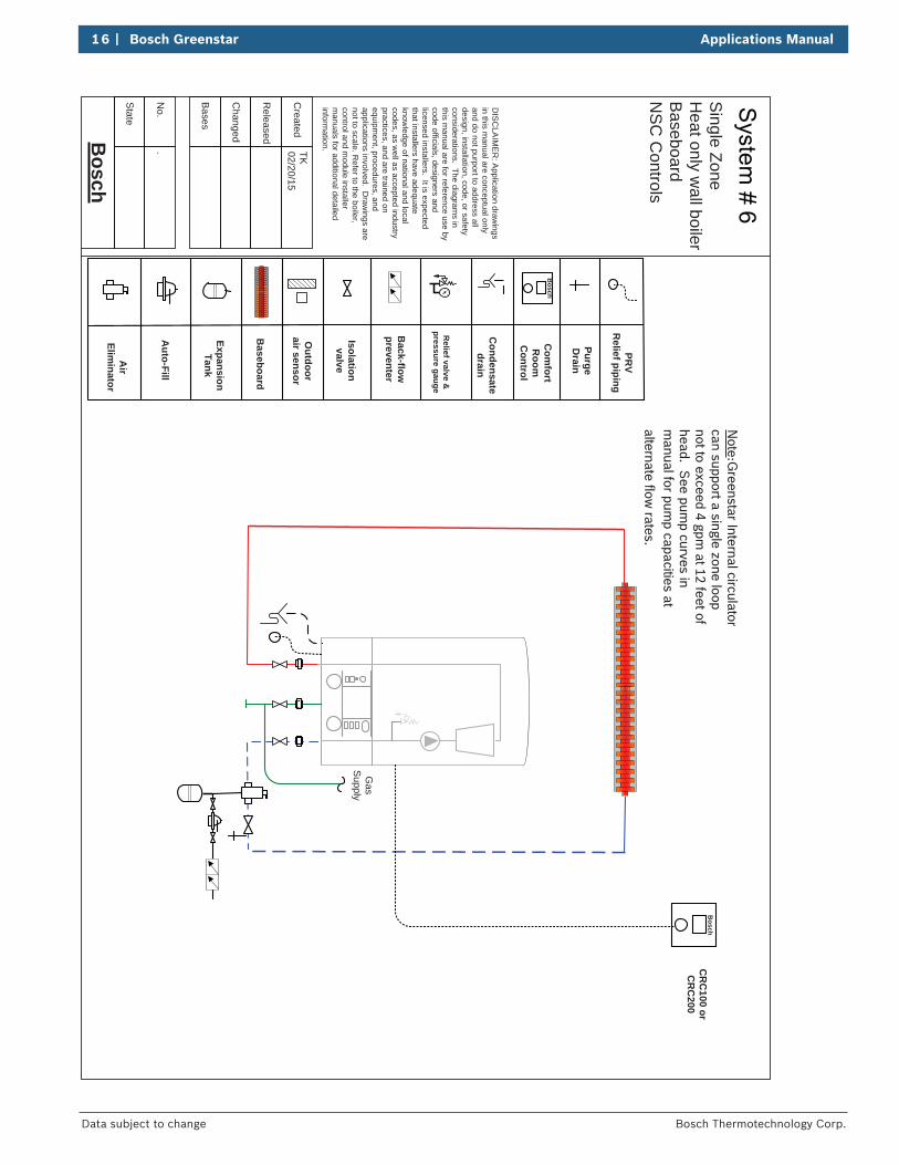
Note:G
reenstar Internal circulator can support a single zone loop not to exceed 4 gpm
at 12 feet of head. S
ee pump curves in
manual for pum
p capacities at alternate flow
rates.
Single Zone
Heat only w
all boilerB
aseboardN
SC
Controls
Applications Manual Bosch Greenstar | 17
Bosch Thermotechnology Corp. Data subject to change
System #6
reset
eco
1
2
3 45
6
max1
2
3 4
e
6
max
Boiler Heating
Dial1
2
3
Typical supply temperatures
approx. 95 °F (35 °C)approx. 109 °F (43 °C)
approx. 122 °F (50 °C)
4
5
6
approx. 140 °F (60 °C)
approx. 153 °F (67 °C)
approx. 167 °F (75 °C)
max Approx. 194 °F (90°C)
Application
Frost protection
Radiant floor heating
Panel radiator system
Cast Iron radiator system
Baseboard & convector system
CRC100 or CRC200
Bosch
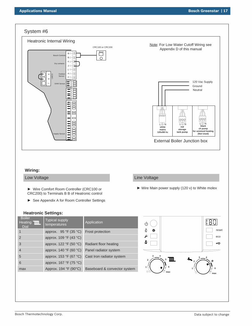
See Appendix A for Room Controller Settings
Low Voltage
Wiring:Line Voltage
Wire Comfort Room Controller (CRC100 or CRC200) to Terminals B B of Heatronic control
Wire Main power supply (120 v) to White molex
Heatronic Settings:
Heatronic Internal Wiring
B
B
4
2
1
A
F
97
8 LWC
O
Supply Sensor
DHW Sensor
Dry contacts
Bosch Controls
Outdoor Sensor
External Boiler Junction box
120 Vac SupplyGroundNeutral
L Nred
storagetank pump
L Nblack
ch pump for unmixed heating
(Not Used)
L Nwhitemains
120v/60 hz
Note: For Low Water Cutoff Wiring see Appendix D of this manual
18 | Bosch Greenstar Applications Manual
Bosch Thermotechnology Corp.Data subject to change
Bosch
State
Bases
No.
.
Changed
Released
Created
Baseboard
Expansion Tank
Auto-Fill
Air
Eliminator
Isolation valve
Back-flow
preventer
Relief valve &
pressure gauge
Condensate
drain
Outdoor
air sensor
Room
Therm
ostat
PurgeD
rain
DIS
CLA
IME
R: A
pplication drawings
in this manual are conceptual only
and do not purport to address all design, installation, code, or safety considerations. The diagram
s in this m
anual are for reference use by code officials, designers and licensed installers. It is expected that installers have adequate know
ledge of national and local codes, as w
ell as accepted industry practices, and are trained on equipm
ent, procedures, and applications involved. D
rawings are
not to scale. Refer to the boiler,
control and module installer
manuals for additional detailed
information.
Gas
Supply
PRV
Relief piping
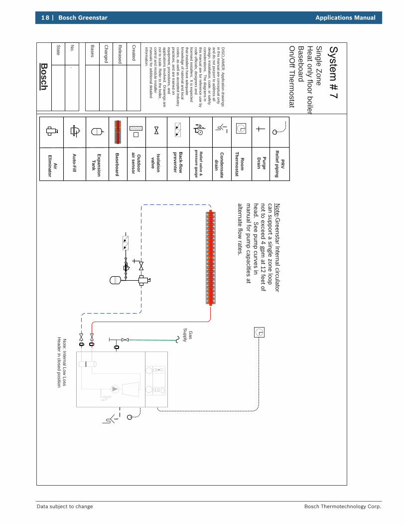
Note: Internal Low
Loss H
eader in closed position
Note:G
reenstar Internal circulator can support a single zone loop not to exceed 4 gpm
at 12 feet of head. S
ee pump curves in
manual for pum
p capacities at alternate flow
rates.
Single Zone
Heat only floor boiler
Baseboard
On/O
ff Thermostat
Applications Manual Bosch Greenstar | 19
Bosch Thermotechnology Corp. Data subject to change
System #7
Room Thermostat
BUS TT out sen LWCO DHW sen
1 2 3 4 5 6
reset
eco
1
2
3 45
6
max1
2
3 4
e
6
max
Boiler Heating
Dial1
2
3
Typical supply temperatures
approx. 95 °F (35 °C)
approx. 109 °F (43 °C)
approx. 122 °F (50 °C)
4
5
6
approx. 140 °F (60 °C)
approx. 153 °F (67 °C)
approx. 167 °F (75 °C)
max Approx. 194 °F (90°C)
Application
Frost protection
Radiant floor heating
Panel radiator system
Cast Iron radiator system
Baseboard & convector system
Neutral
120 V Line
Ground
Low Voltage Wiring Line Voltage Wiring
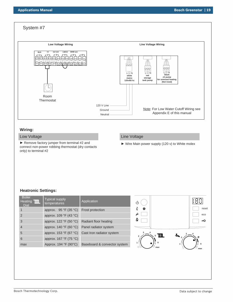
Heatronic Settings:
Low Voltage Remove factory jumper from terminal #2 and
connect non-power robbing thermostat (dry contacts only) to terminal #2
Wiring:Line Voltage
Wire Main power supply (120 v) to White molex
L Nred
storagetank pump
L Nblack
ch pump for unmixed heating
(Not Used)
L Nwhitemains
120v/60 hz
Note: For Low Water Cutoff Wiring see Appendix E of this manual
20 | Bosch Greenstar Applications Manual
Bosch Thermotechnology Corp.Data subject to change
Bosch
State
Bases
No.
.
Changed
Released
Created
Baseboard
Expansion Tank
Auto-Fill
Air
Eliminator
Isolation valve
Back-flow
preventer
Relief valve &
pressure gauge
Condensate
drain
Outdoor
air sensor
Room
Therm
ostat
PurgeD
rain
DIS
CLA
IME
R: A
pplication drawings
in this manual are conceptual only
and do not purport to address all design, installation, code, or safety considerations. The diagram
s in this m
anual are for reference use by code officials, designers and licensed installers. It is expected that installers have adequate know
ledge of national and local codes, as w
ell as accepted industry practices, and are trained on equipm
ent, procedures, and applications involved. D
rawings are
not to scale. Refer to the boiler,
control and module installer
manuals for additional detailed
information.
Gas
Supply
PRV
Relief piping
Note: Internal Low
Loss H
eader in closed position
Bosch
CR
C100 or C
RC
200
Note:G
reenstar Internal circulator can support a single zone loop not to exceed 4 gpm
at 12 feet of head. S
ee pump curves in
manual for pum
p capacities at alternate flow
rates.
Single Zone
Heat only floor boiler
Baseboard
NS
C C
ontrols

Applications Manual Bosch Greenstar | 21
Bosch Thermotechnology Corp. Data subject to change
System #8
BUS TT out sen LWCO DHW sen
1 2 3 4 5 6
reset
eco
1
2
3 45
6
max1
2
3 4
e
6
max
Boiler Heating
Dial
1
2
3
Typical supply temperatures
approx. 95 °F (35 °C)
approx. 109 °F (43 °C)
approx. 122 °F (50 °C)
4
5
6
approx. 140 °F (60 °C)
approx. 153 °F (67 °C)
approx. 167 °F (75 °C)
max Approx. 194 °F (90°C)
Application
Frost protection
Radiant floor heating
Panel radiator system
Cast Iron radiator system
Baseboard & convector system
Neutral
120 V Line
Ground
Low Voltage Wiring Line Voltage Wiring
Bosch
CRC100 or CRC200
Heatronic Settings:
Low Voltage
Wiring:Line Voltage
Wire Main power supply (120 v) to White molex Wire Comfort Room Controller (CRC100 or CRC200) to Terminal # 1 on back of Greenstar FS Boiler
See Appendix A for Room Controller Settings
L Nred
storagetank pump
L Nblack
ch pump for unmixed heating
(Not Used)
L Nwhitemains
120v/60 hz
Note: For Low Water Cutoff Wiring see Appendix E of this manual
22 | Bosch Greenstar Applications Manual
Bosch Thermotechnology Corp.Data subject to change
Bosch
Date
...
Bases
No.
Changed
Released
Created
...
Zone relayX X
Expansion Tank
Auto-Fill
Air Elim
inator
Shut-off valve
Back-flow
preventer
PRV R
eliefPiping
Condensate
drain
Room
Therm
ostat
Flow C
heck
Heatingzone
Circulator
Purge Drain
DIS
CLA
IME
R: A
pplication drawings
in this manual are conceptual only
and do not purport to address all design, installation, code, or safety considerations. The diagram
s in this m
anual are for reference use by code officials, designers and licensed installers. It is expected that installers have adequate know
ledge of national and local codes, as w
ell as accepted industry practices, and are trained on equipm
ent, procedures, and applications involved. D
rawings are
not to scale. Refer to the boiler,
control and module installer
manuals for additional detailed
information.
TT
TT
TT
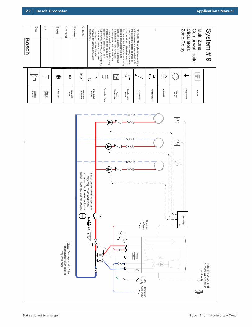
Note: Larger heating system
s m
ay require an additional expansion tank external to the boiler – see m
anual for details.
Dom
esticC
old Water
Dom
esticH
ot Water
Gas
Supply
(Use of FW
200 and outdoor air sensor is
optional)FW
200
SupplySensor
Outdoor
Sensor
Note: S
ee Appendix B
for P
rimary/S
econdary piping requirem
ents
Multi Zone
Com
bi wall boiler
Circulators
Zone Relay
Applications Manual Bosch Greenstar | 23
Bosch Thermotechnology Corp. Data subject to change
System # 9
reset
eco
1
2
3 45
6
max1
2
3 4
e
6
max
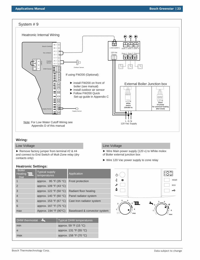
Boiler Heating
Dial1
2
3
Typical supply temperatures
approx. 95 °F (35 °C)
approx. 109 °F (43 °C)
approx. 122 °F (50 °C)
4
5
6
approx. 140 °F (60 °C)
approx. 153 °F (67 °C)
approx. 167 °F (75 °C)
max Approx. 194 °F (90°C)
Application
Frost protection
Radiant floor heating
Panel radiator system
Cast Iron radiator system
Baseboard & convector system
Heatronic Settings:
Low Voltage Remove factory jumper from terminal #2 & #4
and connect to End Switch of Mult-Zone relay (dry contacts only)
Wiring:Line Voltage
Wire Main power supply (120 v) to White molex of Boiler external junction box
Outdoor Sensor
install FW200 on front of boiler (see manual)
install outdoor air sensor Follow FW200 Quick
Set-up guide in Appendix C
If using FW200 (Optional):
Heatronic Internal Wiring
B
B
4
2
1
A
F
97
8 LWC
O
Supply Sensor
DHW Sensor
Dry contacts
Bosch Controls
Outdoor Sensor
Supply Sensor
( end switch )
T TT TT T
Zone 3Zone 1 Zone 2
Zone 3Zone 1 Zone 2
L NG
XX
External Boiler Junction box
120 Vac Supply
120 VacPower
Wire 120 Vac power supply to zone relay
L Nblack
ch pump for unmixed heating
(Not Used)
L Nwhitemains
120v/60 hz
Note: For Low Water Cutoff Wiring see Appendix D of this manual
DHW thermostat
min
e
max
Typical DHW temperatures
approx. 59 °F (15 °C)
approx. 131 °F (55 °C)
approx. 158 °F (70 °C)
24 | Bosch Greenstar Applications Manual
Bosch Thermotechnology Corp.Data subject to change
Bosch
Date
...
Bases
No.
Changed
Released
Created
...
Expansion Tank
Auto-Fill
Air Elim
inator
Shut-off valve
Back-flow
preventer
PRV R
eliefPiping
Condensate
drain
Room
Therm
ostat
Flow C
heck
Heatingzone
Circulator
Purge Drain
DIS
CLA
IME
R: A
pplication drawings
in this manual are conceptual only
and do not purport to address all design, installation, code, or safety considerations. The diagram
s in this m
anual are for reference use by code officials, designers and licensed installers. It is expected that installers have adequate know
ledge of national and local codes, as w
ell as accepted industry practices, and are trained on equipm
ent, procedures, and applications involved. D
rawings are
not to scale. Refer to the boiler,
control and module installer
manuals for additional detailed
information.
TT
TT
TT
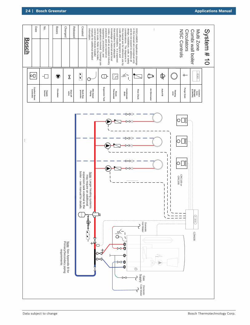
Note: Larger heating system
s m
ay require an additional expansion tank external to the boiler – see m
anual for details.
Dom
esticC
old Water
Dom
esticH
ot Water
Gas
Supply
SupplySensor
Note: S
ee Appendix B
for P
rimary/S
econdary piping requirem
ents
Com
fort Room
C
ontroller
Bosch
Com
fortZone
Manager
(CZM
100)
CR
C100 or
CR
C200
CZM
100
Bosch
Bosch
Multi Zone
Com
bi wall boiler
Circulators
NS
C C
ontrols

Applications Manual Bosch Greenstar | 25
Bosch Thermotechnology Corp. Data subject to change
System #10
reset
eco
1
2
3 45
6
max1
2
3 4
e
6
max
Boiler Heating
Dial1
2
3
Typical supply temperatures
approx. 95 °F (35 °C)
approx. 109 °F (43 °C)
approx. 122 °F (50 °C)
4
5
6
approx. 140 °F (60 °C)
approx. 153 °F (67 °C)
approx. 167 °F (75 °C)
max Approx. 194 °F (90°C)
Application
Frost protection
Radiant floor heating
Panel radiator system
Cast Iron radiator system
Baseboard & convector system
Heatronic Settings:
Low Voltage
Wiring:Line Voltage
Heatronic Internal Wiring
L NG
External Boiler Junction box
120 Vac Supply
Bosch BoschBosch
CRC100 or CRC200CZM100
VZ3VZ1T0 24VACVZ21 2 1 2 1 2 1 2 1 23 4 3 43 4
PZ3PZ2PZ1120 VAC
LNLNLNLN
< 24 V
BUS1 2 1 2 1 2 1 2
BUS BUS BUS
120 VAC
1
4 5 6
0
32 1 2 3 4
See CZM100Manual for additional
Wiring informationB
B
4
2
1
A
F
97
8 LWC
O
Supply Sensor
DHW Sensor
Dry contacts
Bosch Controls
Outdoor Sensor
Supply Sensor
Wire BUS terminal of CZM100 to Terminal BB of Greenstar boiler
Wire Main power supply (120 v) to White molex of Boiler (external junction box) and to 120 VAC input of CZM100 Wire CRC controllers to BUS terminals of
CZM100 Wire 120 VAC ouputs of PZ1, PZ2 and PZ3 of CZM100 to Zone Circulators See Appendix A for Room Controller Settings
L Nblack
ch pump for unmixed heating
(Not Used)
L Nwhitemains
120v/60 hz
Note: For Low Water Cutoff Wiring see Appendix D of this manual
Wire Supply Sensor to “TO” connection on CZM100
DHW thermostat
min
e
max
Typical DHW temperatures
approx. 59 °F (15 °C)
approx. 131 °F (55 °C)
approx. 158 °F (70 °C)
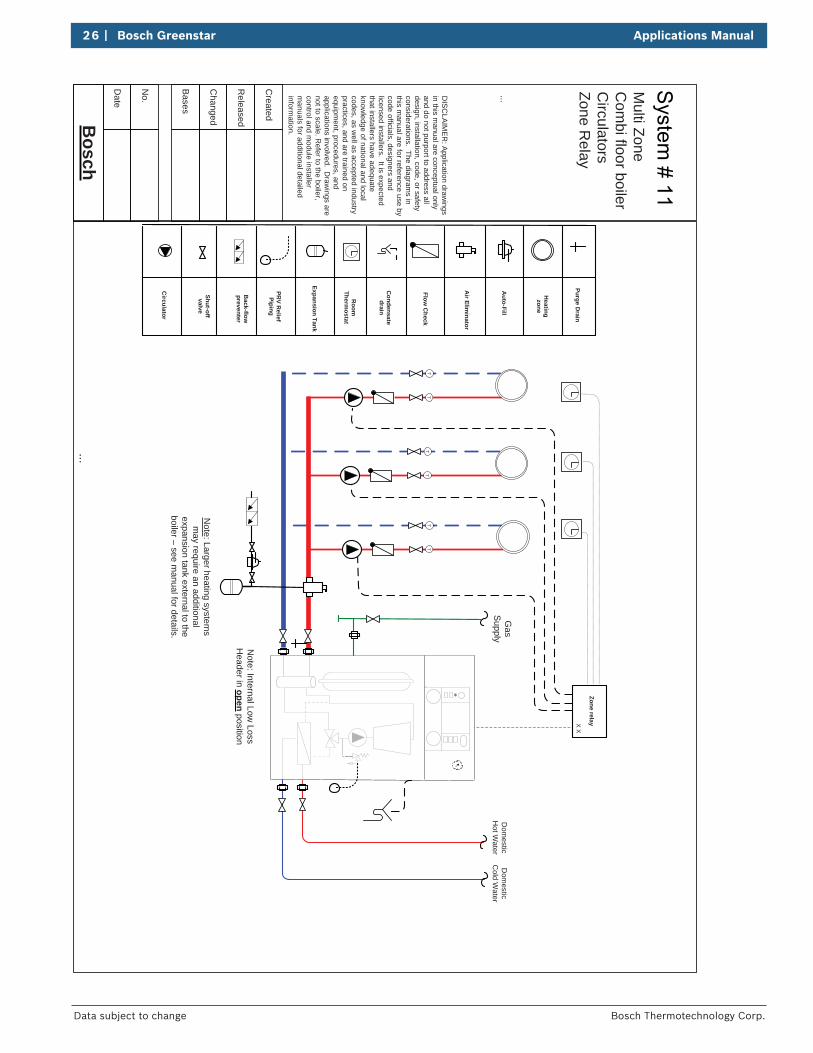
26 | Bosch Greenstar Applications Manual
Bosch Thermotechnology Corp.Data subject to change
Bosch
Date
...
Bases
No.
Changed
Released
Created
...
Zone relayX X
Expansion Tank
Auto-Fill
Air Elim
inator
Shut-off valve
Back-flow
preventer
PRV R
eliefPiping
Condensate
drain
Room
Thermostat
Flow C
heck
Heatingzone
Circulator
Purge Drain
DIS
CLA
IME
R: A
pplication drawings
in this manual are conceptual only
and do not purport to address all design, installation, code, or safety considerations. The diagram
s in this m
anual are for reference use by code officials, designers and licensed installers. It is expected that installers have adequate know
ledge of national and local codes, as w
ell as accepted industry practices, and are trained on equipm
ent, procedures, and applications involved. D
rawings are
not to scale. Refer to the boiler,
control and module installer
manuals for additional detailed
information.
Dom
esticC
old Water
Dom
esticH
ot Water
Gas
Supply
TT
TT
TT
Note: Larger heating system
s m
ay require an additional expansion tank external to the boiler – see m
anual for details. Note: Internal Low
Loss H
eader in open position
Multi Zone
Com
bi floor boilerC
irculatorsZone R
elay
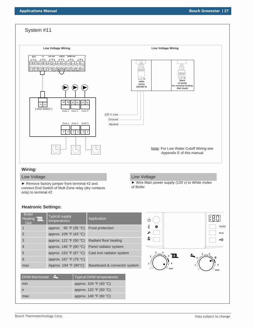
Applications Manual Bosch Greenstar | 27
Bosch Thermotechnology Corp. Data subject to change
System #11
BUS TT out sen LWCO DHW sen
1 2 3 4 5 6
reset
eco
1
2
3 45
6
max1
2
3 4
e
6
max
DHW thermostat
min
e
max
Typical DHW temperatures
approx. 104 °F (40 °C)
approx. 122 °F (50 °C)
approx. 140 °F (60 °C)
Boiler Heating
Dial1
2
3
Typical supply temperatures
approx. 95 °F (35 °C)
approx. 109 °F (43 °C)
approx. 122 °F (50 °C)
4
5
6
approx. 140 °F (60 °C)
approx. 153 °F (67 °C)
approx. 167 °F (75 °C)
max Approx. 194 °F (90°C)
Application
Frost protection
Radiant floor heating
Panel radiator system
Cast Iron radiator system
Baseboard & convector system
Neutral
120 V Line
Ground
Low Voltage Wiring Line Voltage Wiring
Heatronic Settings:
Low Voltage Remove factory jumper from terminal #2 and
connect End Switch of Mult-Zone relay (dry contacts only) to terminal #2
Wiring:Line Voltage
Wire Main power supply (120 v) to White molex of Boiler
( end switch )
T TT TT T
X1 X2
Zone 3Zone 1 Zone 2
H N
Zone 3Zone 1 Zone 2
H N H N
L Nblack
ch pump for unmixed heating
(Not Used)
L Nwhitemains
120v/60 hz
Note: For Low Water Cutoff Wiring see Appendix E of this manual

28 | Bosch Greenstar Applications Manual
Bosch Thermotechnology Corp.Data subject to change
Bosch
Date
...
Bases
No.
Changed
Released
Created
...
Expansion Tank
Auto-Fill
Air Elim
inator
Shut-off valve
Back-flow
preventer
PRV R
eliefPiping
Condensate
drain
Com
fortR
oomC
ontroller
Flow C
heck
Heatingzone
Circulator
Purge Drain
DIS
CLA
IME
R: A
pplication drawings
in this manual are conceptual only
and do not purport to address all design, installation, code, or safety considerations. The diagram
s in this m
anual are for reference use by code officials, designers and licensed installers. It is expected that installers have adequate know
ledge of national and local codes, as w
ell as accepted industry practices, and are trained on equipm
ent, procedures, and applications involved. D
rawings are
not to scale. Refer to the boiler,
control and module installer
manuals for additional detailed
information.
Dom
esticC
old Water
Dom
esticH
ot Water
Gas
Supply
TT
TT
TT
Note: Larger heating system
s m
ay require an additional expansion tank external to the boiler – see m
anual for details.
Bosch
Bosch
Bosch
CR
C100 or
CR
C200
CZM
100C
omfort Zone
Manager
(CZM
100)
Note: Internal Low
Loss H
eader in open position
Multi Zone
Com
bi floor boilerC
irculatorsN
SC
Controls
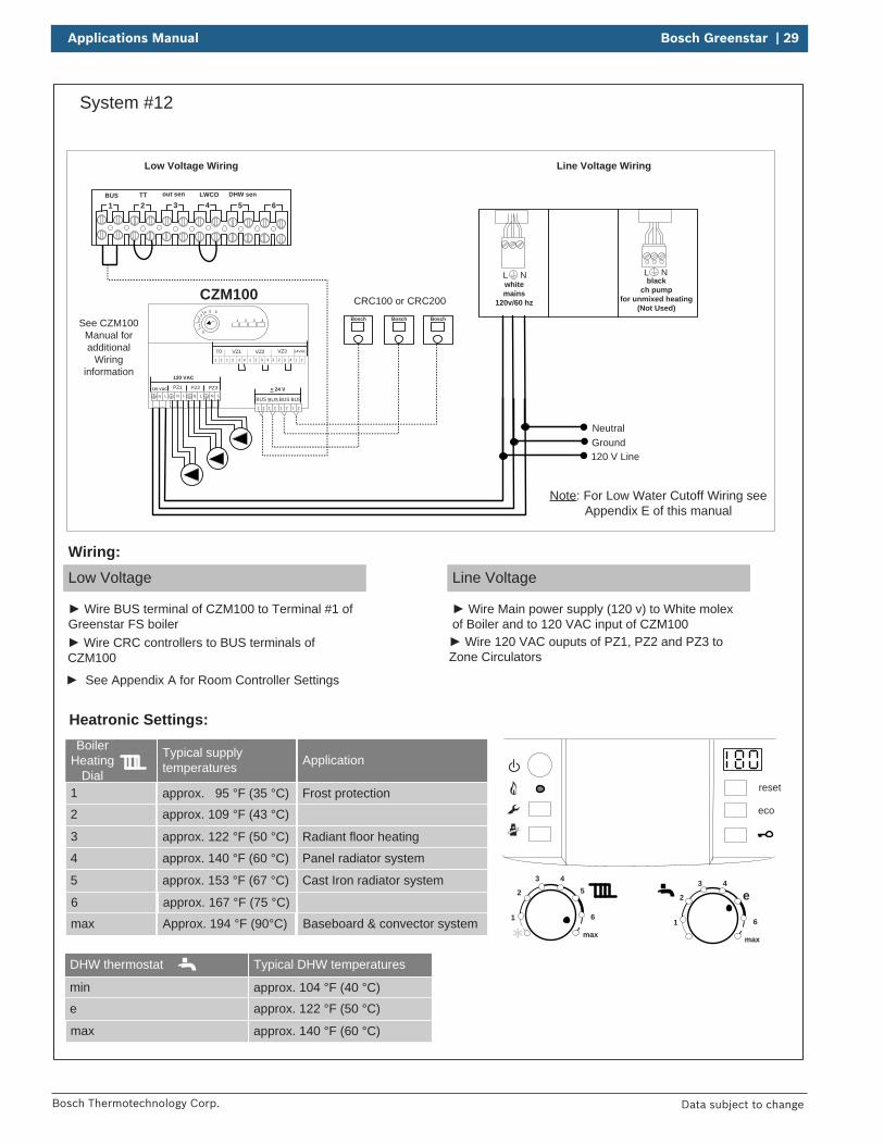
Applications Manual Bosch Greenstar | 29
Bosch Thermotechnology Corp. Data subject to change
System #12
BUS TT out sen LWCO DHW sen
1 2 3 4 5 6
reset
eco
1
2
3 45
6
max1
2
3 4
e
6
max
DHW thermostat
min
e
max
Typical DHW temperatures
approx. 104 °F (40 °C)
approx. 122 °F (50 °C)
approx. 140 °F (60 °C)
Boiler Heating
Dial1
2
3
Typical supply temperatures
approx. 95 °F (35 °C)approx. 109 °F (43 °C)
approx. 122 °F (50 °C)
4
5
6
approx. 140 °F (60 °C)
approx. 153 °F (67 °C)
approx. 167 °F (75 °C)
max Approx. 194 °F (90°C)
Application
Frost protection
Radiant floor heating
Panel radiator system
Cast Iron radiator system
Baseboard & convector system
Neutral
120 V LineGround
Low Voltage Wiring Line Voltage Wiring
Heatronic Settings:
Low Voltage
Wire BUS terminal of CZM100 to Terminal #1 of Greenstar FS boiler
Wiring:Line Voltage
Wire Main power supply (120 v) to White molex of Boiler and to 120 VAC input of CZM100
Bosch BoschBosch
CRC100 or CRC200
Wire CRC controllers to BUS terminals of CZM100
Wire 120 VAC ouputs of PZ1, PZ2 and PZ3 to Zone Circulators
CZM100
VZ3VZ1T0 24VACVZ21 2 1 2 1 2 1 2 1 23 4 3 43 4
PZ3PZ2PZ1120 VAC
LNLNLNLN
< 24 V
BUS1 2 1 2 1 2 1 2
BUS BUS BUS
120 VAC
1
4 5 6
0
32 1 2 3 4See CZM100
Manual for additional
Wiring information
See Appendix A for Room Controller Settings
L Nblack
ch pump for unmixed heating
(Not Used)
L Nwhitemains
120v/60 hz
Note: For Low Water Cutoff Wiring see Appendix E of this manual
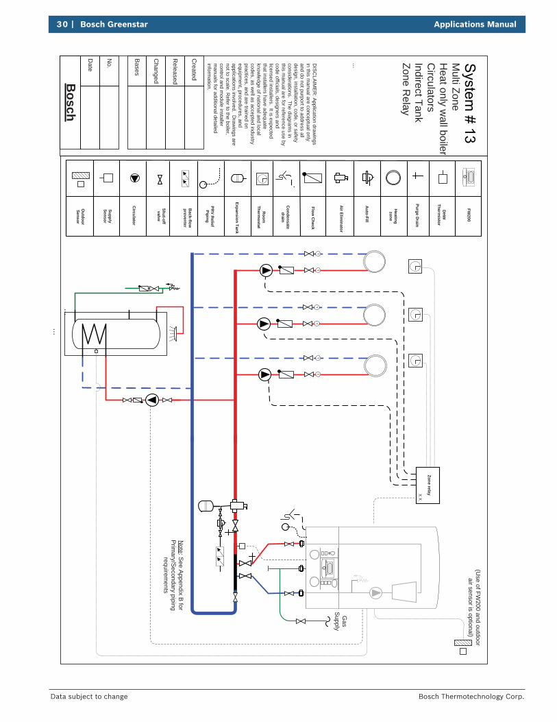
30 | Bosch Greenstar Applications Manual
Bosch Thermotechnology Corp.Data subject to change
Bosch
Date
...
Bases
No.
Changed
Released
Created
...
Zone relayX X
Expansion Tank
Auto-Fill
Air Elim
inator
Shut-off valve
Back-flow
preventer
PRV R
eliefPiping
Condensate
drain
Room
Therm
ostat
Flow C
heck
Heatingzone
Circulator
Purge Drain
DIS
CLA
IME
R: A
pplication drawings
in this manual are conceptual only
and do not purport to address all design, installation, code, or safety considerations. The diagram
s in this m
anual are for reference use by code officials, designers and licensed installers. It is expected that installers have adequate know
ledge of national and local codes, as w
ell as accepted industry practices, and are trained on equipm
ent, procedures, and applications involved. D
rawings are
not to scale. Refer to the boiler,
control and module installer
manuals for additional detailed
information.
TT
TT
TT
(Use of FW
200 and outdoor air sensor is optional)
DH
WTherm
istor
SupplySensor
Outdoor
Sensor
Note: S
ee Appendix B
for P
rimary/S
econdary piping requirem
ents
Gas
Supply
...
FW200
Multi Zone
Heat only w
all boilerC
irculatorsIndirect TankZone R
elay
Applications Manual Bosch Greenstar | 31
Bosch Thermotechnology Corp. Data subject to change
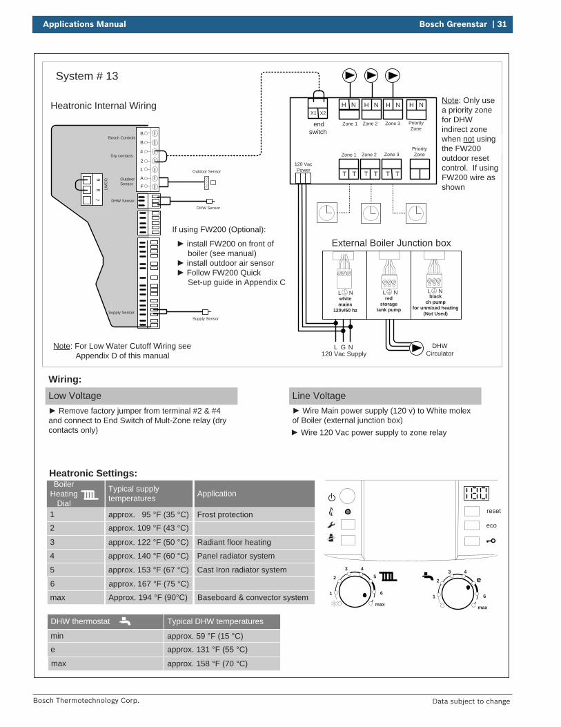
System # 13
reset
eco
1
2
3 45
6
max1
2
3 4
e
6
max
Boiler Heating
Dial1
2
3
Typical supply temperatures
approx. 95 °F (35 °C)
approx. 109 °F (43 °C)
approx. 122 °F (50 °C)
4
5
6
approx. 140 °F (60 °C)
approx. 153 °F (67 °C)
approx. 167 °F (75 °C)
max Approx. 194 °F (90°C)
Application
Frost protection
Radiant floor heating
Panel radiator system
Cast Iron radiator system
Baseboard & convector system
Heatronic Settings:
Low Voltage Remove factory jumper from terminal #2 & #4
and connect to End Switch of Mult-Zone relay (dry contacts only)
Wiring:Line Voltage
Wire Main power supply (120 v) to White molex of Boiler (external junction box)
Outdoor Sensor
L NG
If using FW200 (Optional):
External Boiler Junction box
120 Vac Supply
Heatronic Internal Wiring
B
B
4
2
1
A
F
97
8 LWC
O
Supply Sensor
DHW Sensor
Dry contacts
Bosch Controls
Outdoor Sensor
Supply Sensor
Wire 120 Vac power supply to zone relay
end switch
T TT TT T
X1 X2
Zone 3Zone 1 Zone 2
H N
Zone 3Zone 1 Zone 2
H N H N
PriorityZone
H N
PriorityZone
120 VacPower
DHW Sensor
Note: Only use a priority zone for DHW indirect zone when not using the FW200 outdoor reset control. If using FW200 wire as shown
DHWCirculator
install FW200 on front of boiler (see manual)
install outdoor air sensor Follow FW200 Quick
Set-up guide in Appendix C L Nred
storagetank pump
L Nblack
ch pump for unmixed heating
(Not Used)
L Nwhitemains
120v/60 hz
Note: For Low Water Cutoff Wiring see Appendix D of this manual
DHW thermostat
min
e
max
Typical DHW temperatures
approx. 59 °F (15 °C)
approx. 131 °F (55 °C)
approx. 158 °F (70 °C)
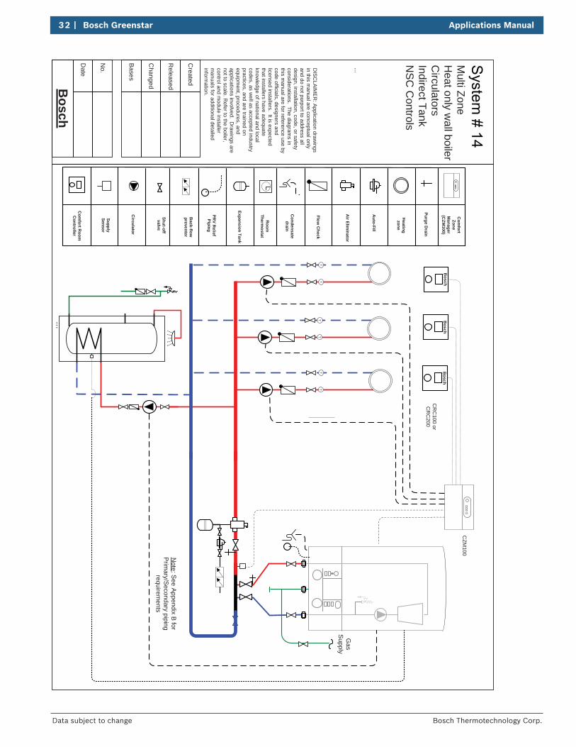
32 | Bosch Greenstar Applications Manual
Bosch Thermotechnology Corp.Data subject to change
Bosch
Date
...
Bases
No.
Changed
Released
Created
...
Expansion Tank
Auto-Fill
Air Elim
inator
Shut-off valve
Back-flow
preventer
PRV R
eliefPiping
Condensate
drain
Room
Thermostat
Flow C
heck
Heatingzone
Circulator
Purge Drain
DIS
CLA
IME
R: A
pplication drawings
in this manual are conceptual only
and do not purport to address all design, installation, code, or safety considerations. The diagram
s in this m
anual are for reference use by code officials, designers and licensed installers. It is expected that installers have adequate know
ledge of national and local codes, as w
ell as accepted industry practices, and are trained on equipm
ent, procedures, and applications involved. D
rawings are
not to scale. Refer to the boiler,
control and module installer
manuals for additional detailed
information.
TT
TT
TT
SupplySensor
Note: S
ee Appendix B for
Prim
ary/Secondary piping
requirements
Com
fort Room
C
ontroller
Bosch
Com
fortZone
Manager
(CZM
100)
CR
C100 or
CR
C200
CZM
100
Bosch
Bosch
Gas
Supply
Multi Zone
Heat only w
all boilerC
irculatorsIndirect TankN
SC
Controls
Applications Manual Bosch Greenstar | 33
Bosch Thermotechnology Corp. Data subject to change
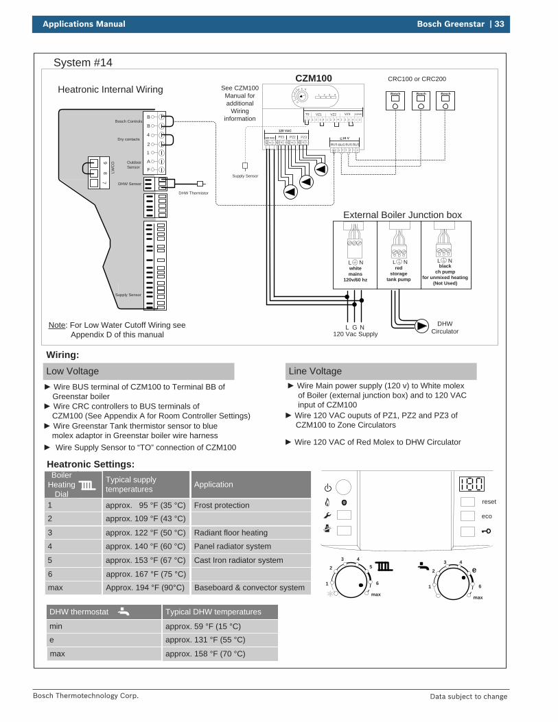
System #14
reset
eco
1
2
3 45
6
max1
2
3 4
e
6
max
Boiler Heating
Dial1
2
3
Typical supply temperatures
approx. 95 °F (35 °C)
approx. 109 °F (43 °C)
approx. 122 °F (50 °C)
4
5
6
approx. 140 °F (60 °C)
approx. 153 °F (67 °C)
approx. 167 °F (75 °C)
max Approx. 194 °F (90°C)
Application
Frost protection
Radiant floor heating
Panel radiator system
Cast Iron radiator system
Baseboard & convector system
Heatronic Settings:
Low Voltage
Wiring:Line Voltage
Heatronic Internal Wiring
L NG
External Boiler Junction box
120 Vac Supply
Bosch BoschBosch
CRC100 or CRC200CZM100
VZ3VZ1T0 24VACVZ21 2 1 2 1 2 1 2 1 23 4 3 43 4
PZ3PZ2PZ1120 VAC
LNLNLNLN
< 24 V
BUS1 2 1 2 1 2 1 2
BUS BUS BUS
120 VAC
1
4 5 6
0
32 1 2 3 4
See CZM100Manual for additional
Wiring informationB
B
4
2
1
A
F
97
8 LWC
O
Supply Sensor
DHW Sensor
Dry contacts
Bosch Controls
Outdoor Sensor
Wire BUS terminal of CZM100 to Terminal BB of Greenstar boiler
Wire Main power supply (120 v) to White molex of Boiler (external junction box) and to 120 VAC input of CZM100 Wire CRC controllers to BUS terminals of
CZM100 (See Appendix A for Room Controller Settings) Wire 120 VAC ouputs of PZ1, PZ2 and PZ3 of CZM100 to Zone Circulators
Wire Supply Sensor to “TO” connection of CZM100
DHW Thermistor
Wire Greenstar Tank thermistor sensor to blue molex adaptor in Greenstar boiler wire harness
DHWCirculator
Wire 120 VAC of Red Molex to DHW Circulator
L Nred
storagetank pump
L Nblack
ch pump for unmixed heating
(Not Used)
L Nwhitemains
120v/60 hz
Note: For Low Water Cutoff Wiring see Appendix D of this manual
Supply Sensor
DHW thermostat
min
e
max
Typical DHW temperatures
approx. 59 °F (15 °C)
approx. 131 °F (55 °C)
approx. 158 °F (70 °C)
34 | Bosch Greenstar Applications Manual
Bosch Thermotechnology Corp.Data subject to change
Bosch
Date
...
Bases
No.
Changed
Released
Created
...
Zone relayX X
DH
W
Aquastat
Expansion Tank
Auto-Fill
Air Elim
inator
Shut-off valve
Back-flow
preventer
PRV R
eliefPiping
Condensate
drain
Room
Thermostat
Flow C
heck
Heatingzone
Dom
esticH
ot Water
Circulator
Purge Drain
DIS
CLA
IME
R: A
pplication drawings
in this manual are conceptual only
and do not purport to address all design, installation, code, or safety considerations. The diagram
s in this m
anual are for reference use by code officials, designers and licensed installers. It is expected that installers have adequate know
ledge of national and local codes, as w
ell as accepted industry practices, and are trained on equipm
ent, procedures, and applications involved. D
rawings are
not to scale. Refer to the boiler,
control and module installer
manuals for additional detailed
information.
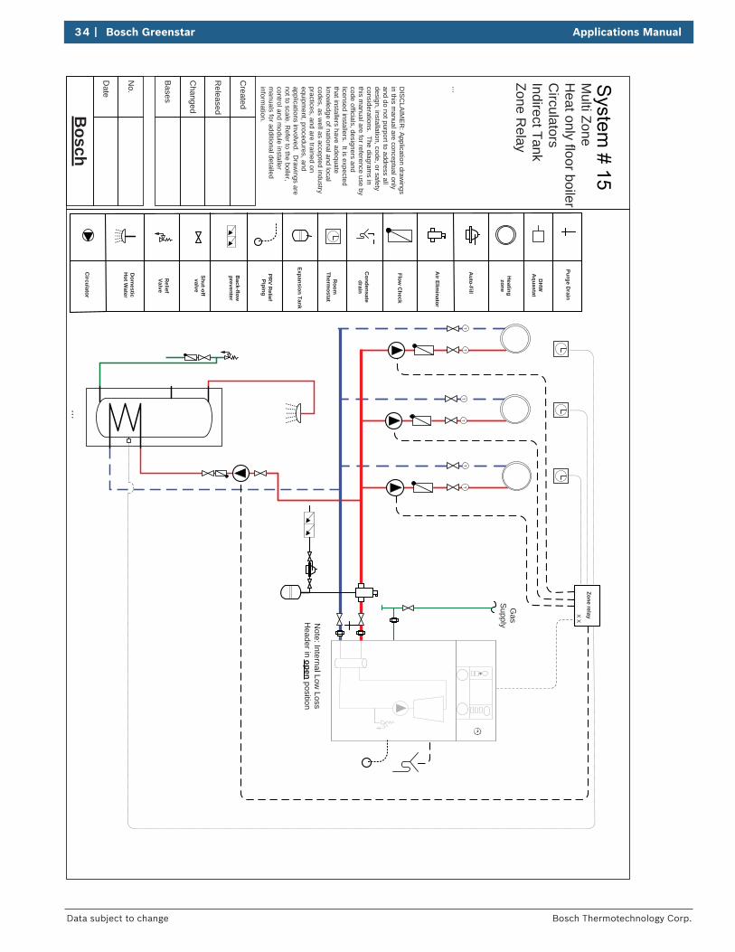
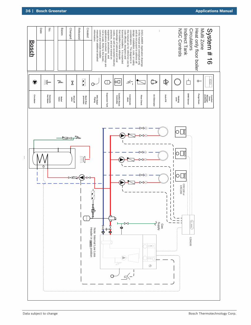
Gas
SupplyN
ote: Internal Low Loss
Header in open position
TT
TT
TT
Relief
Valve
Multi Zone
Heat only floor boiler
Circulators
Indirect TankZone R
elay
Applications Manual Bosch Greenstar | 35
Bosch Thermotechnology Corp. Data subject to change
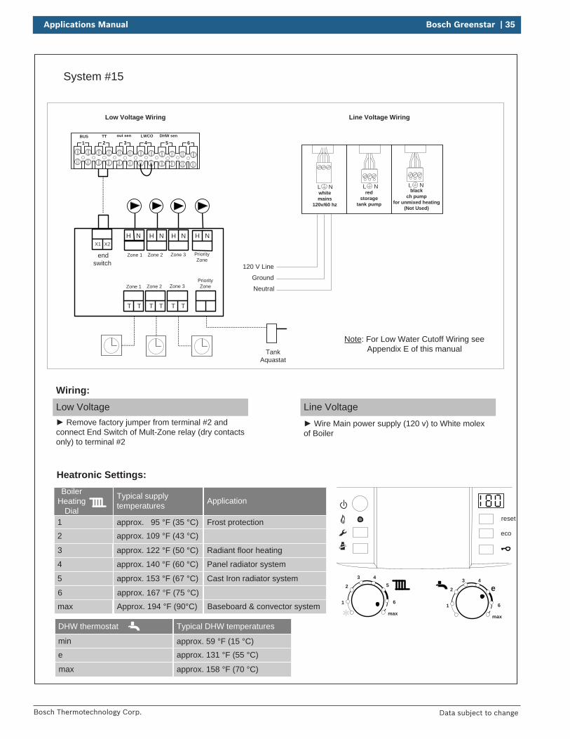
System #15
BUS TT out sen LWCO DHW sen
1 2 3 4 5 6
reset
eco
1
2
3 45
6
max1
2
3 4
e
6
max
Boiler Heating
Dial1
2
3
Typical supply temperatures
approx. 95 °F (35 °C)
approx. 109 °F (43 °C)
approx. 122 °F (50 °C)
4
5
6
approx. 140 °F (60 °C)
approx. 153 °F (67 °C)
approx. 167 °F (75 °C)
max Approx. 194 °F (90°C)
Application
Frost protection
Radiant floor heating
Panel radiator system
Cast Iron radiator system
Baseboard & convector system
Neutral
120 V Line
Ground
Low Voltage Wiring Line Voltage Wiring
Heatronic Settings:
Low Voltage Remove factory jumper from terminal #2 and
connect End Switch of Mult-Zone relay (dry contacts only) to terminal #2
Wiring:Line Voltage
Wire Main power supply (120 v) to White molex of Boiler
end switch
T TT TT T
X1 X2
Zone 3Zone 1 Zone 2
H N
Zone 3Zone 1 Zone 2
H N H N
PriorityZone
H N
PriorityZone
TankAquastat
L Nred
storagetank pump
L Nblack
ch pump for unmixed heating
(Not Used)
L Nwhitemains
120v/60 hz
Note: For Low Water Cutoff Wiring see Appendix E of this manual
DHW thermostat
min
e
max
Typical DHW temperatures
approx. 59 °F (15 °C)approx. 131 °F (55 °C)
approx. 158 °F (70 °C)
36 | Bosch Greenstar Applications Manual
Bosch Thermotechnology Corp.Data subject to change
Bosch
Date
...
Bases
No.
Changed
Released
Created
...
DH
W Sensor
Expansion Tank
Auto-Fill
Air Elim
inator
Shut-off valve
Back-flow
preventer
PRV R
eliefPiping
Condensate
drain
Com
fort Room
C
ontroller
Flow C
heck
Heatingzone
Dom
esticH
ot Water
Circulator
Purge Drain
DIS
CLA
IME
R: A
pplication drawings
in this manual are conceptual only
and do not purport to address all design, installation, code, or safety considerations. The diagram
s in this m
anual are for reference use by code officials, designers and licensed installers. It is expected that installers have adequate know
ledge of national and local codes, as w
ell as accepted industry practices, and are trained on equipm
ent, procedures, and applications involved. D
rawings are
not to scale. Refer to the boiler,
control and module installer
manuals for additional detailed
information.
Gas
Supply
TT
TT
TT
Bosch
Bosch
Bosch
Com
fortZone
Manager
(CZM
100)
CR
C100 or
CR
C200
CZM
100
Relief
Valve
Note: Internal Low
Loss H
eader in open position
Multi Zone
Heat only floor boiler
Circulators
Indirect TankN
SC
Controls
Applications Manual Bosch Greenstar | 37
Bosch Thermotechnology Corp. Data subject to change
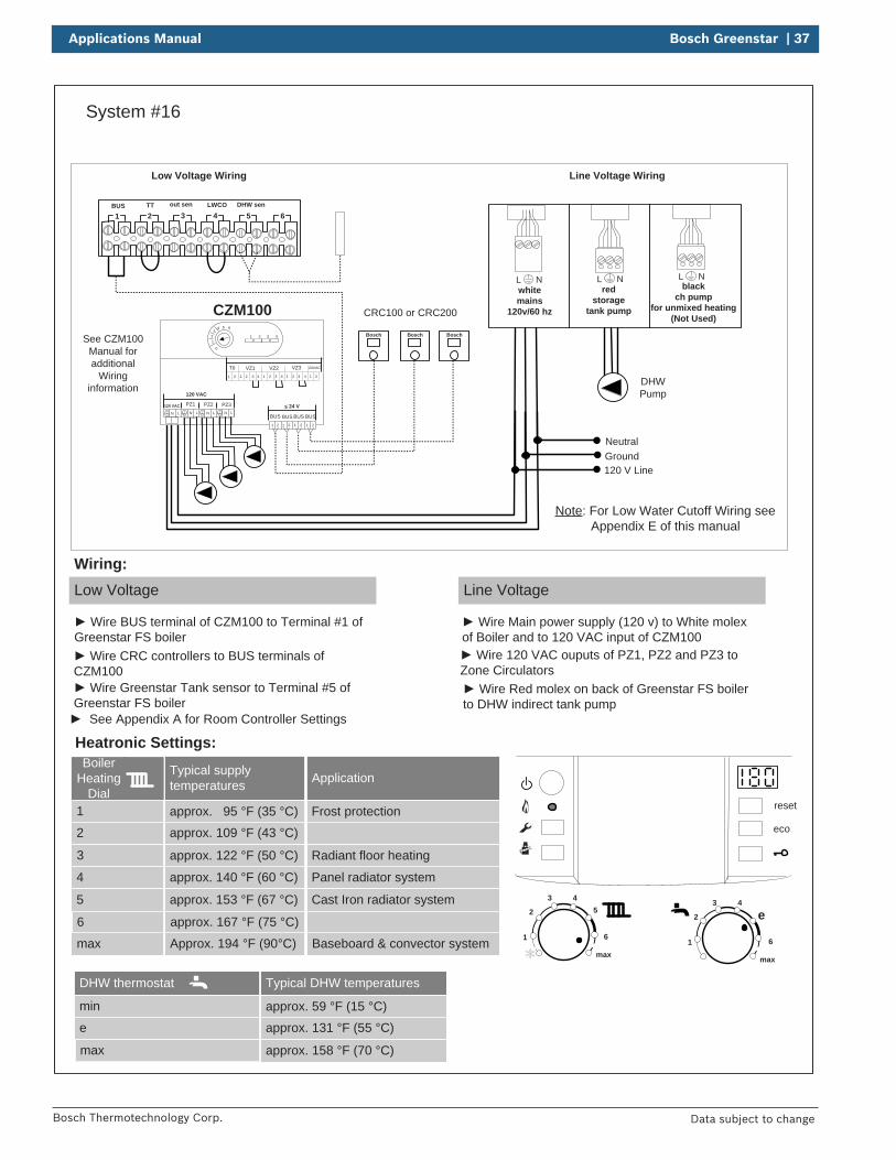
System #16
BUS TT out sen LWCO DHW sen
1 2 3 4 5 6
L Nred
storagetank pump
L Nblack
ch pump for unmixed heating
(Not Used)
L Nwhitemains
120v/60 hz
reset
eco
1
2
3 45
6
max1
2
3 4
e
6
max
Boiler Heating
Dial1
2
3
Typical supply temperatures
approx. 95 °F (35 °C)
approx. 109 °F (43 °C)
approx. 122 °F (50 °C)
4
5
6
approx. 140 °F (60 °C)
approx. 153 °F (67 °C)
approx. 167 °F (75 °C)
max Approx. 194 °F (90°C)
Application
Frost protection
Radiant floor heating
Panel radiator system
Cast Iron radiator system
Baseboard & convector system
Neutral
120 V LineGround
Low Voltage Wiring Line Voltage Wiring
Heatronic Settings:
Low Voltage
Wire BUS terminal of CZM100 to Terminal #1 of Greenstar FS boiler
Wiring:Line Voltage
Wire Main power supply (120 v) to White molex of Boiler and to 120 VAC input of CZM100
CRC100 or CRC200
Wire CRC controllers to BUS terminals of CZM100
Wire 120 VAC ouputs of PZ1, PZ2 and PZ3 to Zone Circulators
Wire Greenstar Tank sensor to Terminal #5 of Greenstar FS boiler
DHWPump
Wire Red molex on back of Greenstar FS boiler to DHW indirect tank pump
Bosch BoschBosch
CZM100
VZ3VZ1T0 24VACVZ21 2 1 2 1 2 1 2 1 23 4 3 43 4
PZ3PZ2PZ1120 VAC
LNLNLNLN
< 24 V
BUS1 2 1 2 1 2 1 2
BUS BUS BUS
120 VAC
1
4 5 6
0
32 1 2 3 4See CZM100
Manual for additional
Wiring information
See Appendix A for Room Controller Settings
Note: For Low Water Cutoff Wiring see Appendix E of this manual
DHW thermostat
min
e
max
Typical DHW temperatures
approx. 59 °F (15 °C)
approx. 131 °F (55 °C)
approx. 158 °F (70 °C)
38 | Bosch Greenstar Applications Manual
Bosch Thermotechnology Corp.Data subject to change
Bosch
Date
...
Bases
No.
Changed
Released
Created
...
Zone relayX X
Expansion Tank
Auto-Fill
Air Elim
inator
Shut-off valve
Back-flow
preventer
PRV R
eliefPiping
Condensate
drain
Room
Thermostat
Flow C
heck
Heatingzone
Circulator
Purge Drain
DIS
CLA
IME
R: A
pplication drawings
in this manual are conceptual only
and do not purport to address all design, installation, code, or safety considerations. The diagram
s in this m
anual are for reference use by code officials, designers and licensed installers. It is expected that installers have adequate know
ledge of national and local codes, as w
ell as accepted industry practices, and are trained on equipm
ent, procedures, and applications involved. D
rawings are
not to scale. Refer to the boiler,
control and module installer
manuals for additional detailed
information.
TT
TT
TT
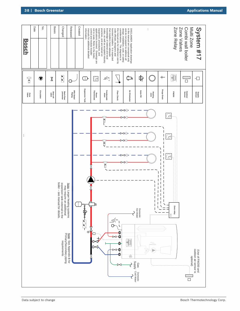
Note: Larger heating system
s m
ay require an additional expansion tank external to the boiler – see m
anual for details.
ZoneValve
Dom
esticC
old Water
Dom
esticH
ot Water
Gas
Supply
(Use of FW
200 and outdoor air sensor is
optional)
Note: See Appendix B
for P
rimary/S
econdary piping requirem
ents
FW200
Outdoor
Sensor
SupplySensor
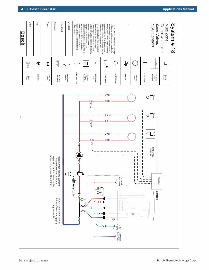
Multi Zone
Com
bi wall boiler
Zone Valves
Zone Relay
Applications Manual Bosch Greenstar | 39
Bosch Thermotechnology Corp. Data subject to change
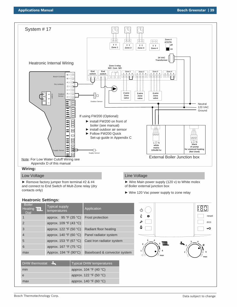
System # 17
reset
eco
1
2
3 45
6
max1
2
3 4
e
6
max
DHW thermostat
min
e
max
Typical DHW temperatures
approx. 104 °F (40 °C)approx. 122 °F (50 °C)
approx. 140 °F (60 °C)
Boiler Heating
Dial1
2
3
Typical supply temperatures
approx. 95 °F (35 °C)
approx. 109 °F (43 °C)
approx. 122 °F (50 °C)
4
5
6
approx. 140 °F (60 °C)
approx. 153 °F (67 °C)
approx. 167 °F (75 °C)
max Approx. 194 °F (90°C)
Application
Frost protection
Radiant floor heating
Panel radiator system
Cast Iron radiator system
Baseboard & convector system
Heatronic Settings:
Low Voltage Remove factory jumper from terminal #2 & #4
and connect to End Switch of Mult-Zone relay (dry contacts only)
Wiring:Line Voltage
Wire Main power supply (120 v) to White molex of Boiler external junction box
Outdoor Sensor
If using FW200 (Optional):
Heatronic Internal Wiring
B
B
4
2
1
A
F
97
8 LWC
O
Supply Sensor
Dry contacts
Bosch Controls
Outdoor Sensor
Supply Sensor
External Boiler Junction box
120 VAC
Wire 120 Vac power supply to zone relay
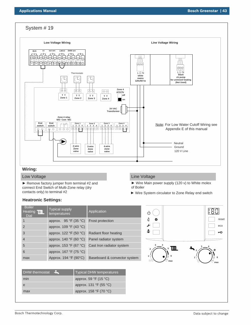
Zone 11 2 3 4
Zone 31 2 3 4
Zone 41 2 3 4
Zone 21 2 3 4
T TZone 1
T TZone 2
T TZone 3
T TZone 4
Endswitch
Endswitch
Zone 4 relayN/O Com N/C
off
on
Zone 4priority
24 VACTransformer
2-wireZone valve
3-wireZonevalve
4-wireZonevalve
Ground
Neutral
install FW200 on front of boiler (see manual)
install outdoor air sensor Follow FW200 Quick
Set-up guide in Appendix C L Nblack
ch pump for unmixed heating
(Not Used)
L Nwhitemains
120v/60 hz
Note: For Low Water Cutoff Wiring see Appendix D of this manual
40 | Bosch Greenstar Applications Manual
Bosch Thermotechnology Corp.Data subject to change
Bosch
Date
...
Bases
No.
Changed
Released
Created
...
Expansion Tank
Auto-Fill
Air Elim
inator
Shut-off valve
Back-flow
preventer
PRV R
eliefPiping
Condensate
drain
Com
fortR
oomC
ontroller
Flow C
heck
Heatingzone
Circulator
Purge Drain
DIS
CLA
IME
R: A
pplication drawings
in this manual are conceptual only
and do not purport to address all design, installation, code, or safety considerations. The diagram
s in this m
anual are for reference use by code officials, designers and licensed installers. It is expected that installers have adequate know
ledge of national and local codes, as w
ell as accepted industry practices, and are trained on equipm
ent, procedures, and applications involved. D
rawings are
not to scale. Refer to the boiler,
control and module installer
manuals for additional detailed
information.
TT
TT
TT
Note: Larger heating system
s m
ay require an additional expansion tank external to the boiler – see m
anual for details.
ZoneValve
Bosch
Bosch
Bosch
CR
C100 or
CR
C200
CZM
100C
omfort
ZoneM
anager
Dom
esticC
old Water
Dom
esticH
ot Water
Gas
Supply
Note: S
ee Appendix B
for P
rimary/S
econdary piping requirem
ents
SupplySensor
Multi Zone
Com
bi wall boiler
Zone Valves
NS
C C
ontrols
Applications Manual Bosch Greenstar | 41
Bosch Thermotechnology Corp. Data subject to change
Neutral120 V Line
Ground
See CZM100Manual for
Detail wiring
CRC100 or CRC200
CZM100
Bosch Bosch
VZ3VZ1T0 24VACVZ21 2 1 2 1 2 1 2 1 23 4 3 43 4
24 VACTransformer
2-wire, 3 -wire and 4- wire zone valves
120 Vac24 Vac
PZ3PZ2PZ1120 VAC
LNLNLNLN
< 24 V
BUS1 2 1 2 1 2 1 2
BUS BUS BUS
120 VAC
Bosch
1
4 5 6
0
32 1 2 3 4
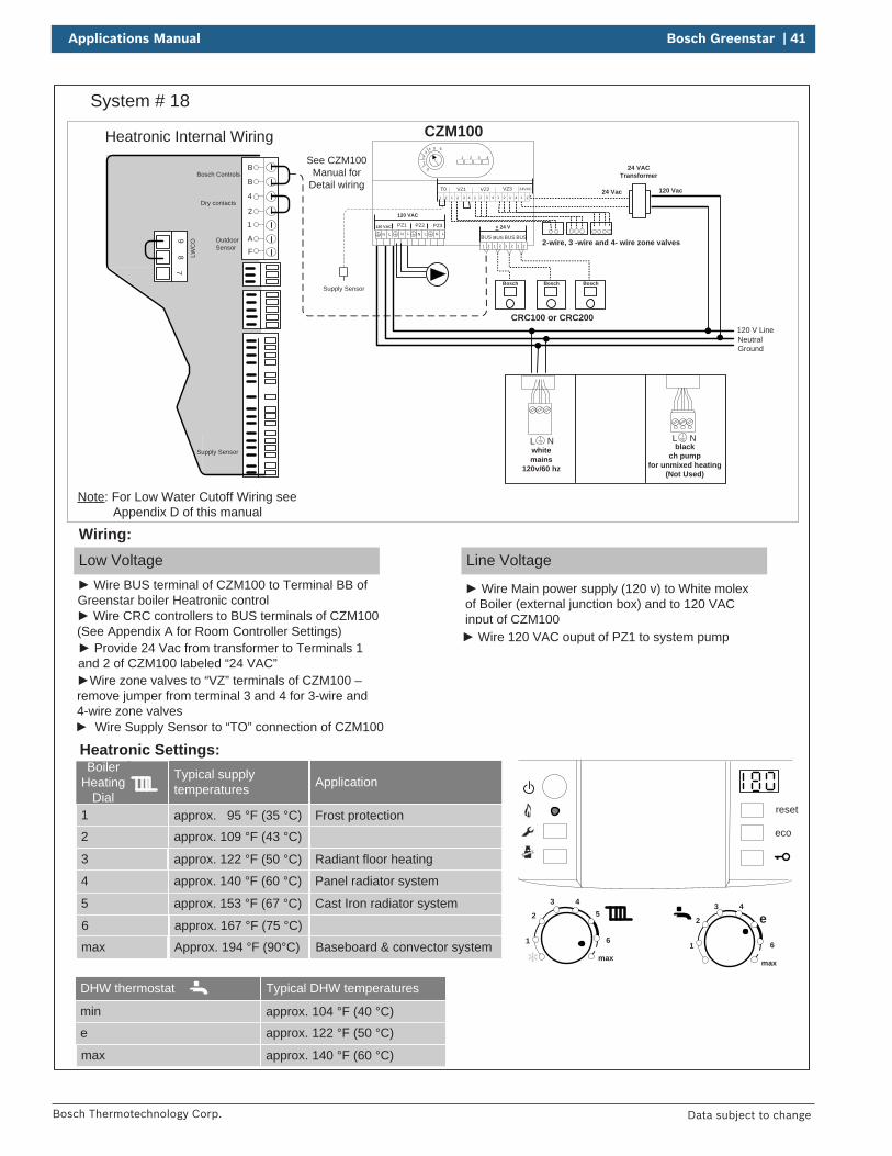
System # 18
reset
eco
1
2
3 45
6
max1
2
3 4
e
6
max
DHW thermostat
min
e
max
Typical DHW temperatures
approx. 104 °F (40 °C)
approx. 122 °F (50 °C)
approx. 140 °F (60 °C)
Boiler Heating
Dial1
2
3
Typical supply temperatures
approx. 95 °F (35 °C)approx. 109 °F (43 °C)
approx. 122 °F (50 °C)
4
5
6
approx. 140 °F (60 °C)
approx. 153 °F (67 °C)
approx. 167 °F (75 °C)
max Approx. 194 °F (90°C)
Application
Frost protection
Radiant floor heating
Panel radiator system
Cast Iron radiator system
Baseboard & convector system
Heatronic Settings:
Low Voltage
Wiring:Line Voltage
Heatronic Internal Wiring
B
B
4
2
1
A
F
97
8 LWC
O
Supply Sensor
Dry contacts
Bosch Controls
Outdoor Sensor
Wire BUS terminal of CZM100 to Terminal BB of Greenstar boiler Heatronic control
Wire Main power supply (120 v) to White molex of Boiler (external junction box) and to 120 VAC input of CZM100 Wire CRC controllers to BUS terminals of CZM100
(See Appendix A for Room Controller Settings) Wire 120 VAC ouput of PZ1 to system pump Provide 24 Vac from transformer to Terminals 1
and 2 of CZM100 labeled “24 VAC”Wire zone valves to “VZ” terminals of CZM100 –
remove jumper from terminal 3 and 4 for 3-wire and 4-wire zone valves
Wire Supply Sensor to “TO” connection of CZM100
L Nblack
ch pump for unmixed heating
(Not Used)
L Nwhitemains
120v/60 hz
Note: For Low Water Cutoff Wiring see Appendix D of this manual
Supply Sensor
42 | Bosch Greenstar Applications Manual
Bosch Thermotechnology Corp.Data subject to change
Bosch
Date
...
Bases
No.
Changed
Released
Created
...
Zone relayX X
Expansion Tank
Auto-Fill
Air Elim
inator
Shut-off valve
Back-flow
preventer
PRV R
eliefPiping
Condensate
drain
Room
Thermostat
Flow C
heck
Heatingzone
Circulator
Purge Drain
DIS
CLA
IME
R: A
pplication drawings
in this manual are conceptual only
and do not purport to address all design, installation, code, or safety considerations. The diagram
s in this m
anual are for reference use by code officials, designers and licensed installers. It is expected that installers have adequate know
ledge of national and local codes, as w
ell as accepted industry practices, and are trained on equipm
ent, procedures, and applications involved. D
rawings are
not to scale. Refer to the boiler,
control and module installer
manuals for additional detailed
information.
Dom
esticC
old Water
Dom
esticH
ot Water
Gas
Supply
TT
TT
TT
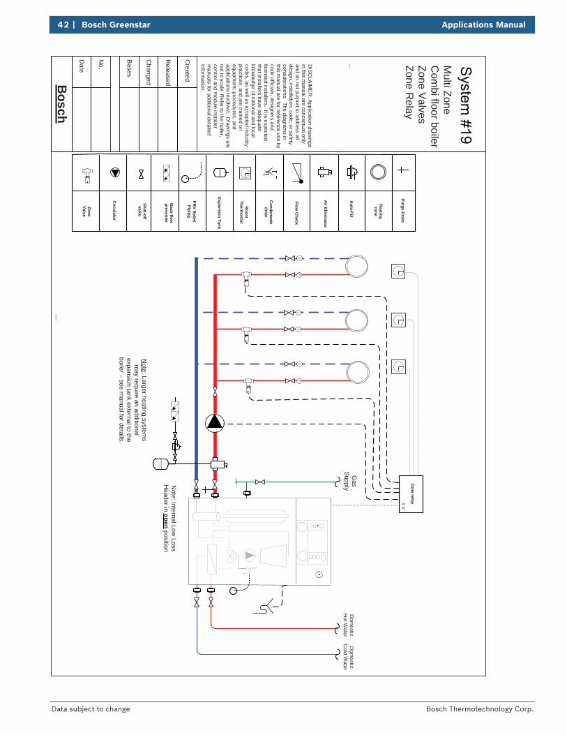
Note: Larger heating system
s m
ay require an additional expansion tank external to the boiler – see m
anual for details.
ZoneValve
Note: Internal Low
Loss H
eader in open position
Multi Zone
Com
bi floor boilerZone V
alvesZone R
elay
Applications Manual Bosch Greenstar | 43
Bosch Thermotechnology Corp. Data subject to change
System # 19
BUS TT out sen LWCO DHW sen
1 2 3 4 5 6
reset
eco
1
2
3 45
6
max1
2
3 4
e
6
max
Boiler Heating
Dial1
2
3
Typical supply temperatures
approx. 95 °F (35 °C)
approx. 109 °F (43 °C)
approx. 122 °F (50 °C)
4
5
6
approx. 140 °F (60 °C)
approx. 153 °F (67 °C)
approx. 167 °F (75 °C)
max Approx. 194 °F (90°C)
Application
Frost protection
Radiant floor heating
Panel radiator system
Cast Iron radiator system
Baseboard & convector system
Neutral
120 V LineGround
Low Voltage Wiring Line Voltage Wiring
Heatronic Settings:
Low Voltage Remove factory jumper from terminal #2 and
connect End Switch of Multi-Zone relay (dry contacts only) to terminal #2
Wiring:Line Voltage
Wire Main power supply (120 v) to White molex of Boiler
Zone 11 2 3 4
Zone 31 2 3 4
Zone 41 2 3 4
Zone 21 2 3 4
T TZone 1
T TZone 2
T TZone 3
T TZone 4
Endswitch
Endswitch
Zone 4 relayN/O Com N/C
off
on
Zone 4priority
24 VACTransformer
2-wireZone valve
3-wireZonevalve
4-wireZonevalve
Thermostats
Wire System circulator to Zone Relay end switch
L Nblack
ch pump for unmixed heating
(Not Used)
L Nwhitemains
120v/60 hz
Note: For Low Water Cutoff Wiring see Appendix E of this manual
DHW thermostat
min
e
max
Typical DHW temperatures
approx. 59 °F (15 °C)
approx. 131 °F (55 °C)
approx. 158 °F (70 °C)
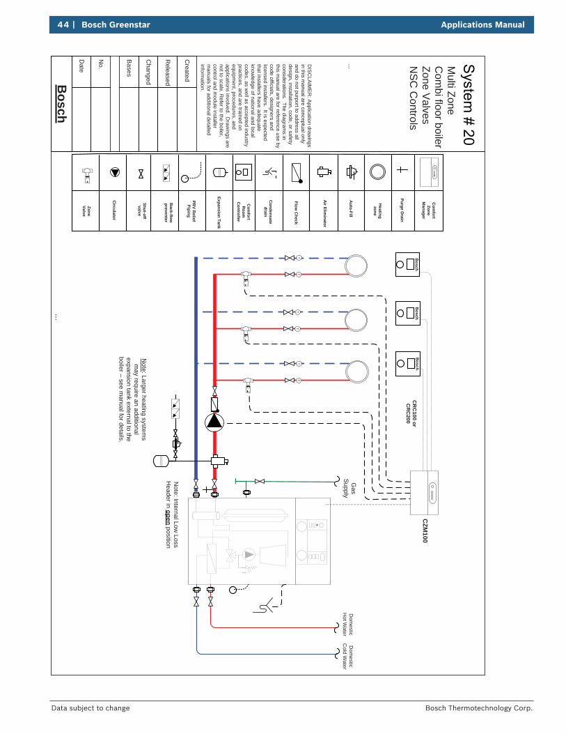
44 | Bosch Greenstar Applications Manual
Bosch Thermotechnology Corp.Data subject to change
Bosch
Date
...
Bases
No.
Changed
Released
Created
...
Expansion Tank
Auto-Fill
Air Elim
inator
Shut-off valve
Back-flow
preventer
PRV R
eliefPiping
Condensate
drain
Com
fortR
oomC
ontroller
Flow C
heck
Heatingzone
Circulator
Purge Drain
DIS
CLA
IME
R: A
pplication drawings
in this manual are conceptual only
and do not purport to address all design, installation, code, or safety considerations. The diagram
s in this m
anual are for reference use by code officials, designers and licensed installers. It is expected that installers have adequate know
ledge of national and local codes, as w
ell as accepted industry practices, and are trained on equipm
ent, procedures, and applications involved. D
rawings are
not to scale. Refer to the boiler,
control and module installer
manuals for additional detailed
information.
Dom
esticC
old Water
Dom
esticH
ot Water
Gas
Supply
TT
TT
TT
Note: Larger heating system
s m
ay require an additional expansion tank external to the boiler – see m
anual for details.
ZoneValve
Bosch
Bosch
Bosch
CR
C100 or
CR
C200
CZM
100C
omfort
ZoneM
anager
Note: Internal Low
Loss H
eader in open position
Multi Zone
Com
bi floor boilerZone V
alvesN
SC
Controls
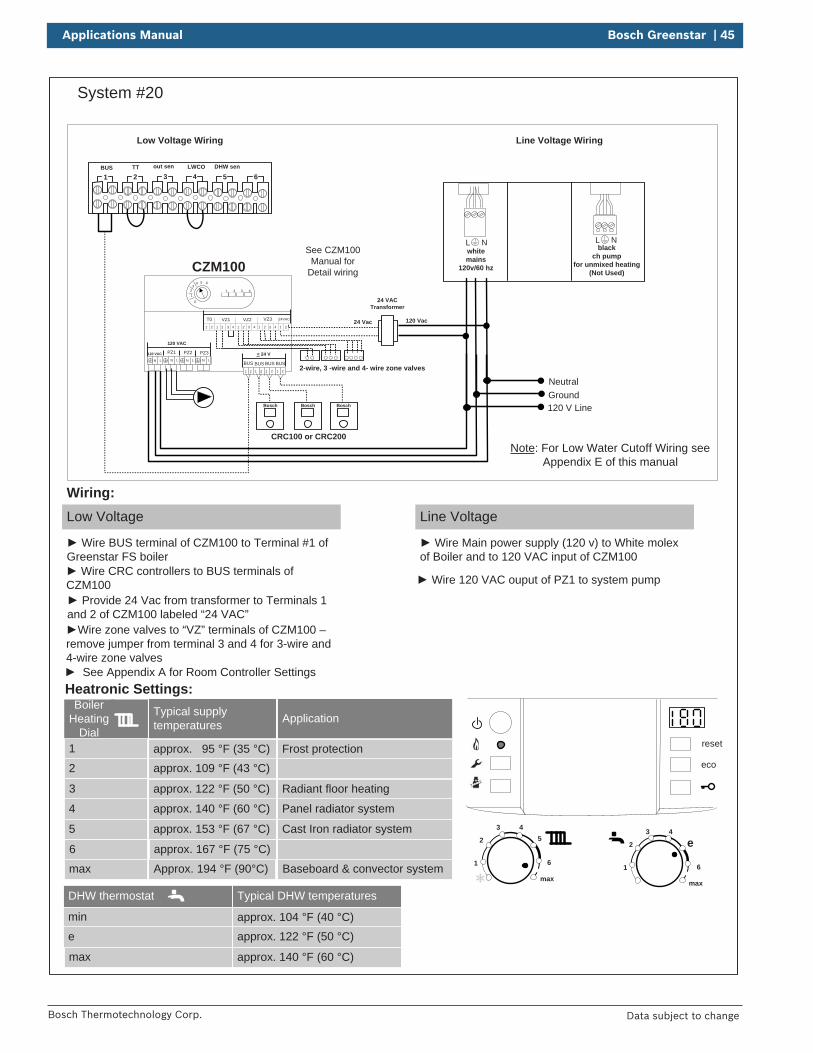
Applications Manual Bosch Greenstar | 45
Bosch Thermotechnology Corp. Data subject to change
System #20
BUS TT out sen LWCO DHW sen
1 2 3 4 5 6
reset
eco
1
2
3 45
6
max1
2
3 4
e
6
max
DHW thermostat
min
e
max
Typical DHW temperatures
approx. 104 °F (40 °C)approx. 122 °F (50 °C)
approx. 140 °F (60 °C)
Boiler Heating
Dial1
2
3
Typical supply temperatures
approx. 95 °F (35 °C)approx. 109 °F (43 °C)
approx. 122 °F (50 °C)
4
5
6
approx. 140 °F (60 °C)
approx. 153 °F (67 °C)
approx. 167 °F (75 °C)
max Approx. 194 °F (90°C)
Application
Frost protection
Radiant floor heating
Panel radiator system
Cast Iron radiator system
Baseboard & convector system
Neutral
120 V LineGround
Low Voltage Wiring Line Voltage Wiring
Heatronic Settings:
Low Voltage
Wire BUS terminal of CZM100 to Terminal #1 of Greenstar FS boiler
Wiring:Line Voltage
Wire Main power supply (120 v) to White molex of Boiler and to 120 VAC input of CZM100
See CZM100Manual for
Detail wiring
CRC100 or CRC200
CZM100
Wire CRC controllers to BUS terminals of CZM100 Wire 120 VAC ouput of PZ1 to system pump
Bosch Bosch
VZ3VZ1T0 24VACVZ21 2 1 2 1 2 1 2 1 23 4 3 43 4
24 VACTransformer
2-wire, 3 -wire and 4- wire zone valves
120 Vac24 Vac
PZ3PZ2PZ1120 VAC
LNLNLNLN
< 24 V
BUS1 2 1 2 1 2 1 2
BUS BUS BUS
120 VAC
Bosch
Provide 24 Vac from transformer to Terminals 1 and 2 of CZM100 labeled “24 VAC”
Wire zone valves to “VZ” terminals of CZM100 –remove jumper from terminal 3 and 4 for 3-wire and 4-wire zone valves
1
4 5 6
0
32 1 2 3 4
See Appendix A for Room Controller Settings
L Nblack
ch pump for unmixed heating
(Not Used)
L Nwhitemains
120v/60 hz
Note: For Low Water Cutoff Wiring see Appendix E of this manual
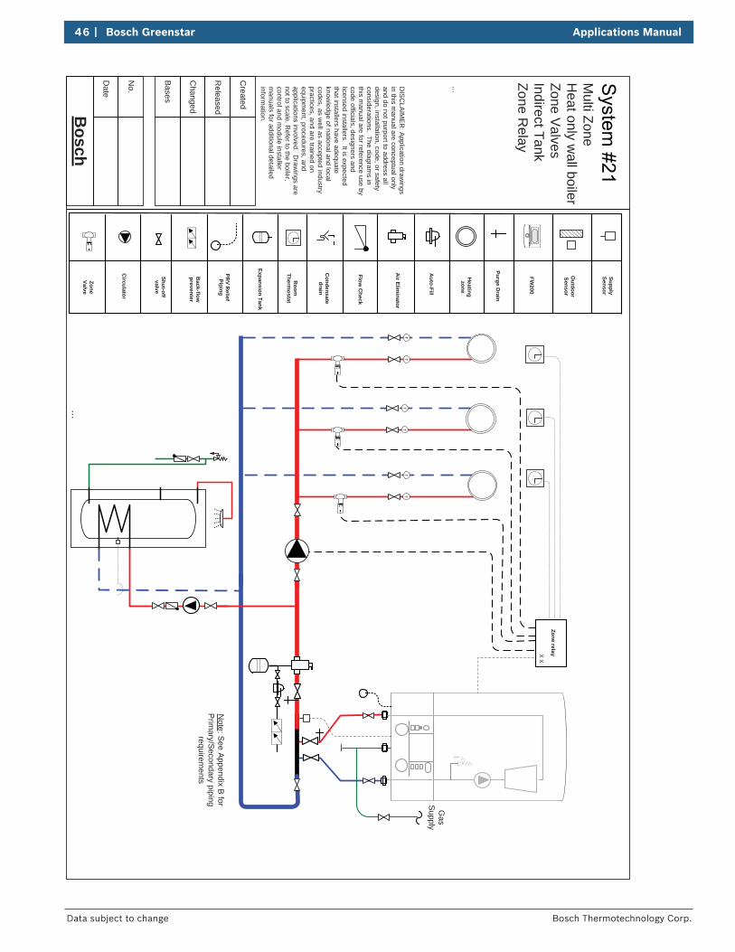
46 | Bosch Greenstar Applications Manual
Bosch Thermotechnology Corp.Data subject to change
Bosch
Date
...
Bases
No.
Changed
Released
Created
...
Zone relayX X
Expansion Tank
Auto-Fill
Air Elim
inator
Shut-off valve
Back-flow
preventer
PRV R
eliefPiping
Condensate
drain
Room
Thermostat
Flow C
heck
Heatingzone
Circulator
Purge Drain
DIS
CLA
IME
R: A
pplication drawings
in this manual are conceptual only
and do not purport to address all design, installation, code, or safety considerations. The diagram
s in this m
anual are for reference use by code officials, designers and licensed installers. It is expected that installers have adequate know
ledge of national and local codes, as w
ell as accepted industry practices, and are trained on equipm
ent, procedures, and applications involved. D
rawings are
not to scale. Refer to the boiler,
control and module installer
manuals for additional detailed
information.
TT
TT
TT
ZoneValve
Note: See Appendix B
for P
rimary/S
econdary piping requirem
ents
FW200
Outdoor
Sensor
Gas
Supply
SupplySensor
Multi Zone
Heat only w
all boilerZone V
alves Indirect TankZone R
elay
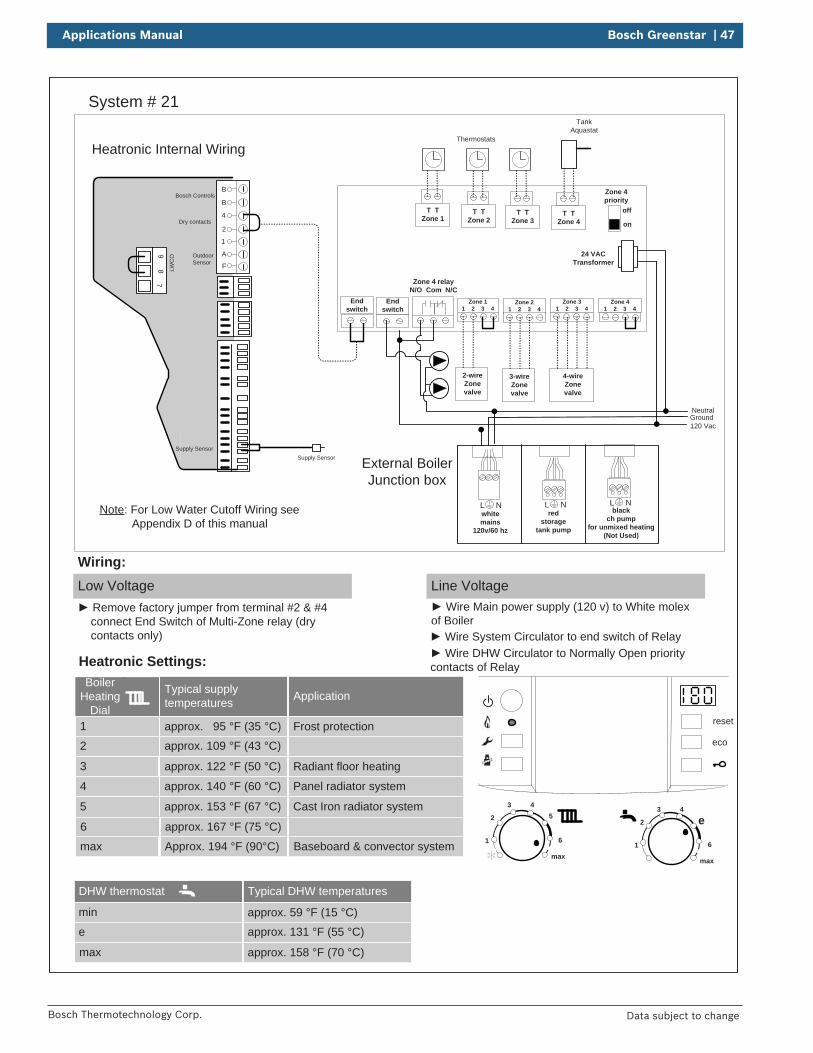
Applications Manual Bosch Greenstar | 47
Bosch Thermotechnology Corp. Data subject to change
System # 21
reset
eco
1
2
3 45
6
max1
2
3 4
e
6
max
Boiler Heating
Dial1
2
3
Typical supply temperatures
approx. 95 °F (35 °C)
approx. 109 °F (43 °C)
approx. 122 °F (50 °C)
4
5
6
approx. 140 °F (60 °C)
approx. 153 °F (67 °C)
approx. 167 °F (75 °C)
max Approx. 194 °F (90°C)
Application
Frost protection
Radiant floor heating
Panel radiator system
Cast Iron radiator system
Baseboard & convector system
NeutralGround
Heatronic Settings:
Low Voltage Remove factory jumper from terminal #2 & #4
connect End Switch of Multi-Zone relay (dry contacts only)
Wiring:Line Voltage
Wire Main power supply (120 v) to White molex of Boiler
Zone 11 2 3 4
Zone 31 2 3 4
Zone 41 2 3 4
Zone 21 2 3 4
T TZone 1
T TZone 2
T TZone 3
T TZone 4
Endswitch
Endswitch
Zone 4 relayN/O Com N/C
off
on
Zone 4priority
24 VACTransformer
2-wireZone valve
3-wireZonevalve
4-wireZonevalve
TankAquastat
Thermostats
Wire System Circulator to end switch of Relay Wire DHW Circulator to Normally Open priority
contacts of Relay
External Boiler Junction box
Heatronic Internal Wiring
B
B
4
2
1
A
F
97
8 LWC
O
Supply Sensor
Dry contacts
Bosch Controls
Outdoor Sensor
Supply Sensor
120 Vac
L Nred
storagetank pump
L Nblack
ch pump for unmixed heating
(Not Used)
L Nwhitemains
120v/60 hz
Note: For Low Water Cutoff Wiring see Appendix D of this manual
DHW thermostat
min
e
max
Typical DHW temperatures
approx. 59 °F (15 °C)
approx. 131 °F (55 °C)
approx. 158 °F (70 °C)
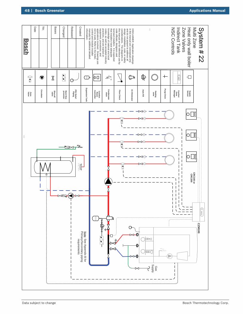
48 | Bosch Greenstar Applications Manual
Bosch Thermotechnology Corp.Data subject to change
Bosch
Date
...
Bases
No.
Changed
Released
Created
...
Expansion Tank
Auto-Fill
Air Elim
inator
Shut-off valve
Back-flow
preventer
PRV R
eliefPiping
Condensate
drain
Com
fortR
oomC
ontroller
Flow C
heck
Heatingzone
Circulator
Purge Drain
DIS
CLA
IME
R: A
pplication drawings
in this manual are conceptual only
and do not purport to address all design, installation, code, or safety considerations. The diagram
s in this m
anual are for reference use by code officials, designers and licensed installers. It is expected that installers have adequate know
ledge of national and local codes, as w
ell as accepted industry practices, and are trained on equipm
ent, procedures, and applications involved. D
rawings are
not to scale. Refer to the boiler,
control and module installer
manuals for additional detailed
information.
TT
TT
TT
ZoneValve
Bosch
Bosch
Bosch
CR
C100 or
CR
C200
CZM
100
Com
fortZone
Manager
Note: S
ee Appendix B
for P
rimary/S
econdary piping requirem
ents
Gas
Supply
SupplySensor
Multi Zone
Heat only w
all boilerZone V
alves Indirect TankN
SC
Controls
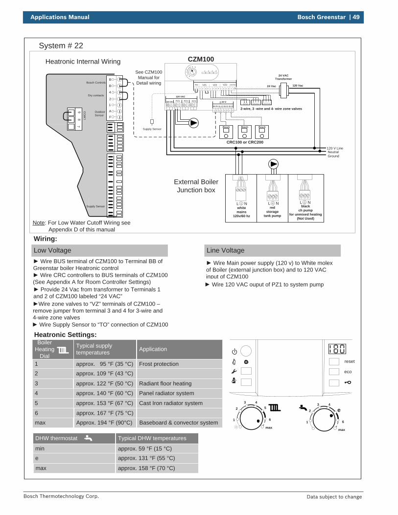
Applications Manual Bosch Greenstar | 49
Bosch Thermotechnology Corp. Data subject to change
Neutral120 V Line
Ground
See CZM100Manual for
Detail wiring
CRC100 or CRC200
CZM100
Bosch Bosch
VZ3VZ1T0 24VACVZ21 2 1 2 1 2 1 2 1 23 4 3 43 4
24 VACTransformer
2-wire, 3 -wire and 4- wire zone valves
120 Vac24 Vac
PZ3PZ2PZ1120 VAC
LNLNLNLN
< 24 V
BUS1 2 1 2 1 2 1 2
BUS BUS BUS
120 VAC
Bosch
1
4 5 6
0
32 1 2 3 4
System # 22
reset
eco
1
2
3 45
6
max1
2
3 4
e
6
max
Boiler Heating
Dial1
2
3
Typical supply temperatures
approx. 95 °F (35 °C)
approx. 109 °F (43 °C)
approx. 122 °F (50 °C)
4
5
6
approx. 140 °F (60 °C)
approx. 153 °F (67 °C)
approx. 167 °F (75 °C)
max Approx. 194 °F (90°C)
Application
Frost protection
Radiant floor heating
Panel radiator system
Cast Iron radiator system
Baseboard & convector system
Heatronic Settings:
Low Voltage
Wiring:Line Voltage
Heatronic Internal Wiring
B
B
4
2
1
A
F
97
8 LWC
O
Supply Sensor
Dry contacts
Bosch Controls
Outdoor Sensor
Wire BUS terminal of CZM100 to Terminal BB of Greenstar boiler Heatronic control
Wire Main power supply (120 v) to White molex of Boiler (external junction box) and to 120 VAC input of CZM100 Wire CRC controllers to BUS terminals of CZM100
(See Appendix A for Room Controller Settings) Wire 120 VAC ouput of PZ1 to system pump Provide 24 Vac from transformer to Terminals 1
and 2 of CZM100 labeled “24 VAC”Wire zone valves to “VZ” terminals of CZM100 –
remove jumper from terminal 3 and 4 for 3-wire and 4-wire zone valves
Wire Supply Sensor to “TO” connection of CZM100
External Boiler Junction box
L Nred
storagetank pump
L Nblack
ch pump for unmixed heating
(Not Used)
L Nwhitemains
120v/60 hz
Note: For Low Water Cutoff Wiring see Appendix D of this manual
Supply Sensor
DHW thermostat
min
e
max
Typical DHW temperatures
approx. 59 °F (15 °C)approx. 131 °F (55 °C)
approx. 158 °F (70 °C)
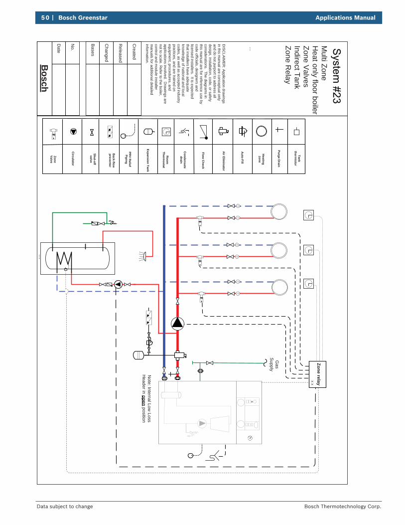
50 | Bosch Greenstar Applications Manual
Bosch Thermotechnology Corp.Data subject to change
Bosch
Date
...
Bases
No.
Changed
Released
Created
...
Zone relayX X
Expansion Tank
Auto-Fill
Air Elim
inator
Shut-off valve
Back-flow
preventer
PRV R
eliefPiping
Condensate
drain
Room
Thermostat
Flow C
heck
Heatingzone
Circulator
Purge Drain
DIS
CLA
IME
R: A
pplication drawings
in this manual are conceptual only
and do not purport to address all design, installation, code, or safety considerations. The diagram
s in this m
anual are for reference use by code officials, designers and licensed installers. It is expected that installers have adequate know
ledge of national and local codes, as w
ell as accepted industry practices, and are trained on equipm
ent, procedures, and applications involved. D
rawings are
not to scale. Refer to the boiler,
control and module installer
manuals for additional detailed
information.
Gas
Supply
TT
TT
TT
ZoneValve
...
Note: Internal Low
Loss H
eader in open position
Tank therm
istor
Multi Zone
Heat only floor boiler
Zone Valves
Indirect TankZone R
elay
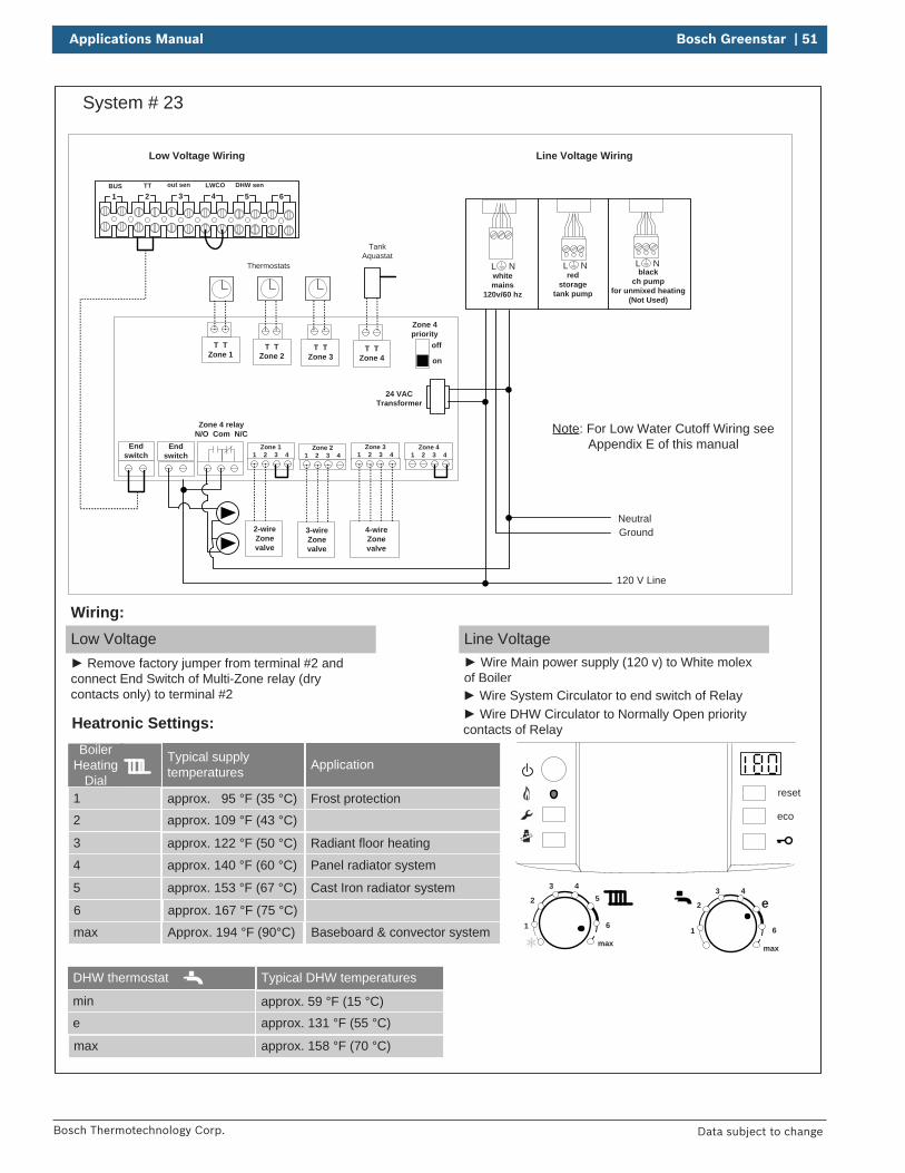
Applications Manual Bosch Greenstar | 51
Bosch Thermotechnology Corp. Data subject to change
System # 23
BUS TT out sen LWCO DHW sen
1 2 3 4 5 6
reset
eco
1
2
3 45
6
max1
2
3 4
e
6
max
Boiler Heating
Dial1
2
3
Typical supply temperatures
approx. 95 °F (35 °C)
approx. 109 °F (43 °C)
approx. 122 °F (50 °C)
4
5
6
approx. 140 °F (60 °C)
approx. 153 °F (67 °C)
approx. 167 °F (75 °C)
max Approx. 194 °F (90°C)
Application
Frost protection
Radiant floor heating
Panel radiator system
Cast Iron radiator system
Baseboard & convector system
Neutral
120 V Line
Ground
Low Voltage Wiring Line Voltage Wiring
Heatronic Settings:
Low Voltage Remove factory jumper from terminal #2 and
connect End Switch of Multi-Zone relay (dry contacts only) to terminal #2
Wiring:Line Voltage
Wire Main power supply (120 v) to White molex of Boiler
Zone 11 2 3 4
Zone 31 2 3 4
Zone 41 2 3 4
Zone 21 2 3 4
T TZone 1
T TZone 2
T TZone 3
T TZone 4
Endswitch
Endswitch
Zone 4 relayN/O Com N/C
off
on
Zone 4priority
24 VACTransformer
2-wireZone valve
3-wireZonevalve
4-wireZonevalve
TankAquastat
Thermostats
Wire System Circulator to end switch of Relay Wire DHW Circulator to Normally Open priority
contacts of Relay
L Nred
storagetank pump
L Nblack
ch pump for unmixed heating
(Not Used)
L Nwhitemains
120v/60 hz
Note: For Low Water Cutoff Wiring see Appendix E of this manual
DHW thermostat
min
e
max
Typical DHW temperatures
approx. 59 °F (15 °C)approx. 131 °F (55 °C)
approx. 158 °F (70 °C)
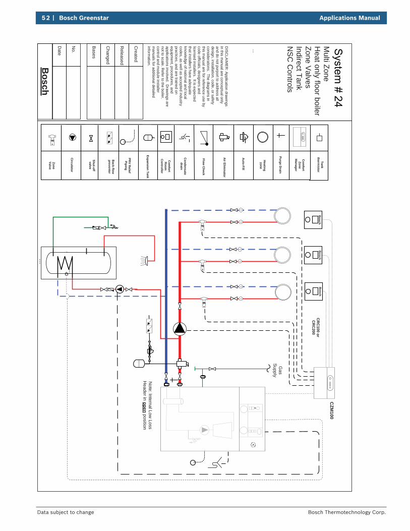
52 | Bosch Greenstar Applications Manual
Bosch Thermotechnology Corp.Data subject to change
Bosch
Date
...
Bases
No.
Changed
Released
Created
...
Expansion Tank
Auto-Fill
Air Elim
inator
Shut-off valve
Back-flow
preventer
PRV R
eliefPiping
Condensate
drain
Com
fortR
oomC
ontroller
Flow C
heck
Heatingzone
Circulator
Purge Drain
DIS
CLA
IME
R: A
pplication drawings
in this manual are conceptual only
and do not purport to address all design, installation, code, or safety considerations. The diagram
s in this m
anual are for reference use by code officials, designers and licensed installers. It is expected that installers have adequate know
ledge of national and local codes, as w
ell as accepted industry practices, and are trained on equipm
ent, procedures, and applications involved. D
rawings are
not to scale. Refer to the boiler,
control and module installer
manuals for additional detailed
information.
Gas
Supply
TT
TT
TT
ZoneValve
...
CZM
100
Bosch
Bosch
Bosch
CR
C100 or
CR
C200
Com
fortZone
Manager
Note: Internal Low
Loss H
eader in open position
Tank therm
istor
Multi Zone
Heat only floor boiler
Zone Valves
Indirect TankN
SC
Controls
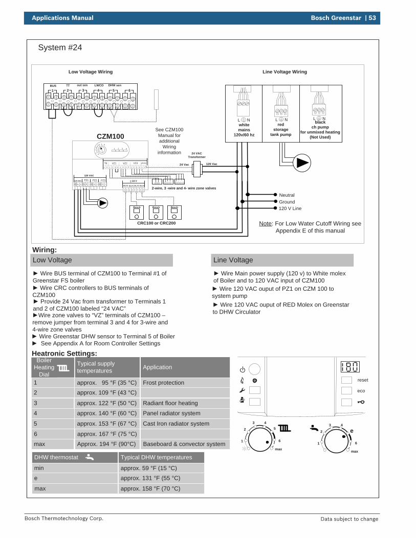
Applications Manual Bosch Greenstar | 53
Bosch Thermotechnology Corp. Data subject to change
System #24
BUS TT out sen LWCO DHW sen
1 2 3 4 5 6
L Nred
storagetank pump
L Nblack
ch pump for unmixed heating
(Not Used)
L Nwhitemains
120v/60 hz
reset
eco
1
2
3 45
6
max1
2
3 4
e
6
max
Boiler Heating
Dial1
2
3
Typical supply temperatures
approx. 95 °F (35 °C)
approx. 109 °F (43 °C)
approx. 122 °F (50 °C)
4
5
6
approx. 140 °F (60 °C)
approx. 153 °F (67 °C)
approx. 167 °F (75 °C)
max Approx. 194 °F (90°C)
Application
Frost protection
Radiant floor heating
Panel radiator system
Cast Iron radiator system
Baseboard & convector system
Neutral
120 V LineGround
Low Voltage Wiring Line Voltage Wiring
Heatronic Settings:
Low Voltage
Wire BUS terminal of CZM100 to Terminal #1 of Greenstar FS boiler
Wiring:Line Voltage
Wire Main power supply (120 v) to White molex of Boiler and to 120 VAC input of CZM100
CRC100 or CRC200
CZM100
Wire CRC controllers to BUS terminals of CZM100
Wire 120 VAC ouput of PZ1 on CZM 100 to system pump
Bosch Bosch
VZ3VZ1T0 24VACVZ21 2 1 2 1 2 1 2 1 23 4 3 43 4
24 VACTransformer
2-wire, 3 -wire and 4- wire zone valves
120 Vac24 Vac
PZ3PZ2PZ1120 VAC
LNLNLNLN
< 24 V
BUS1 2 1 2 1 2 1 2
BUS BUS BUS
120 VAC
Bosch
Provide 24 Vac from transformer to Terminals 1 and 2 of CZM100 labeled “24 VAC”
Wire zone valves to “VZ” terminals of CZM100 –remove jumper from terminal 3 and 4 for 3-wire and 4-wire zone valves
1
4 5 6
0
32 1 2 3 4
Wire Greenstar DHW sensor to Terminal 5 of Boiler
Wire 120 VAC ouput of RED Molex on Greenstar to DHW Circulator
See CZM100Manual for additional
Wiring information
See Appendix A for Room Controller Settings
Note: For Low Water Cutoff Wiring see Appendix E of this manual
DHW thermostat
min
e
max
Typical DHW temperatures
approx. 59 °F (15 °C)
approx. 131 °F (55 °C)
approx. 158 °F (70 °C)
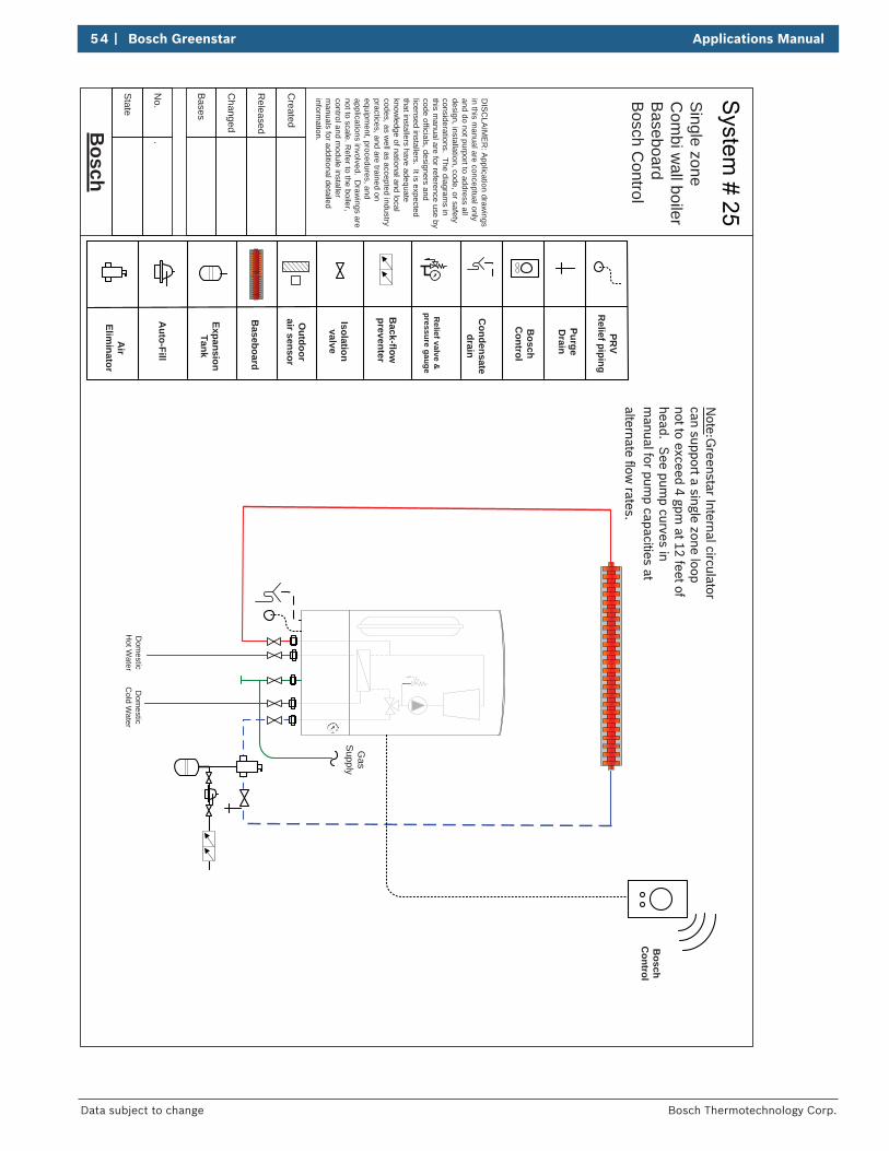
54 | Bosch Greenstar Applications Manual
Bosch Thermotechnology Corp.Data subject to change
Bosch
State
Bases
No.
.
Changed
Released
Created
Baseboard
Expansion Tank
Auto-Fill
Air
Eliminator
Isolation valve
Back-flow
preventer
Relief valve &
pressure gauge
Condensate
drain
Outdoor
air sensor
Bosch
Control
PurgeD
rain
DIS
CLA
IME
R: A
pplication drawings
in this manual are conceptual only
and do not purport to address all design, installation, code, or safety considerations. The diagram
s in this m
anual are for reference use by code officials, designers and licensed installers. It is expected that installers have adequate know
ledge of national and local codes, as w
ell as accepted industry practices, and are trained on equipm
ent, procedures, and applications involved. D
rawings are
not to scale. Refer to the boiler,
control and module installer
manuals for additional detailed
information.
Dom
esticC
old Water
Dom
esticH
ot Water
Gas
Supply
PRV
Relief piping
Single zone
Com
bi wall boiler
Baseboard
Bosch C
ontrol
Note:G
reenstar Internal circulator can support a single zone loop not to exceed 4 gpm
at 12 feet of head. S
ee pump curves in
manual for pum
p capacities at alternate flow
rates.
Bosch
Control
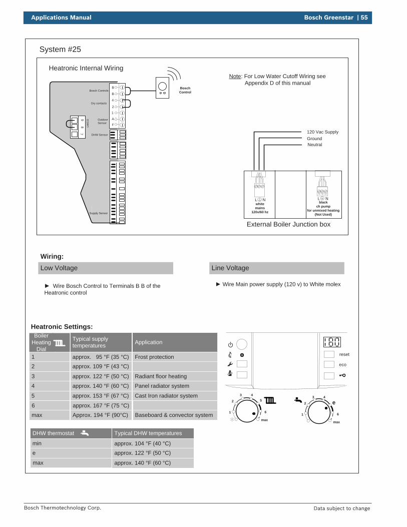
Applications Manual Bosch Greenstar | 55
Bosch Thermotechnology Corp. Data subject to change
System #25
reset
eco
1
2
3 45
6
max1
2
3 4
e
6
max
DHW thermostat
min
e
max
Typical DHW temperatures
approx. 104 °F (40 °C)
approx. 122 °F (50 °C)
approx. 140 °F (60 °C)
Boiler Heating
Dial1
2
3
Typical supply temperatures
approx. 95 °F (35 °C)approx. 109 °F (43 °C)
approx. 122 °F (50 °C)
4
5
6
approx. 140 °F (60 °C)
approx. 153 °F (67 °C)
approx. 167 °F (75 °C)
max Approx. 194 °F (90°C)
Application
Frost protection
Radiant floor heating
Panel radiator system
Cast Iron radiator system
Baseboard & convector system
Low Voltage
Wiring:Line Voltage
Wire Bosch Control to Terminals B B of the Heatronic control
Wire Main power supply (120 v) to White molex
Heatronic Settings:
Heatronic Internal Wiring
B
B
4
2
1
A
F
97
8 LWC
O
Supply Sensor
DHW Sensor
Dry contacts
Bosch Controls
Outdoor Sensor
External Boiler Junction box
120 Vac SupplyGroundNeutral
L Nblack
ch pump for unmixed heating
(Not Used)
L Nwhitemains
120v/60 hz
Note: For Low Water Cutoff Wiring see Appendix D of this manual
BoschControl
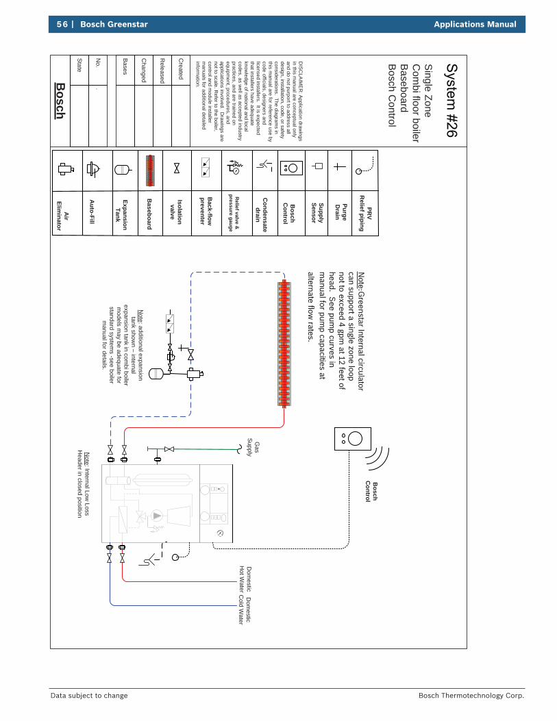
56 | Bosch Greenstar Applications Manual
Bosch Thermotechnology Corp.Data subject to change
Bosch
State
Bases
No.
.
Changed
Released
Created
Baseboard
Expansion Tank
Auto-Fill
Air
Eliminator
Isolation valve
Back-flow
preventer
Relief valve &
pressure gauge
Condensate
drain
Bosch
Control
SupplySensor
PurgeD
rain
DIS
CLA
IME
R: A
pplication drawings
in this manual are conceptual only
and do not purport to address all design, installation, code, or safety considerations. The diagram
s in this m
anual are for reference use by code officials, designers and licensed installers. It is expected that installers have adequate know
ledge of national and local codes, as w
ell as accepted industry practices, and are trained on equipm
ent, procedures, and applications involved. D
rawings are
not to scale. Refer to the boiler,
control and module installer
manuals for additional detailed
information.
Dom
esticC
old Water
Dom
esticH
ot Water
Gas
Supply
PRV
Relief piping
Note: Internal Low
Loss H
eader in closed position
Note: additional expansion tank show
n – internal expansion tank in com
bi boiler m
odels may be adequate for
standard systems -see boiler
manual for details.
Note:G
reenstar Internal circulator can support a single zone loop not to exceed 4 gpm
at 12 feet of head. S
ee pump curves in
manual for pum
p capacities at alternate flow
rates.
Single Zone
Com
bi floor boilerB
aseboardB
osch Control
Bosch
Control
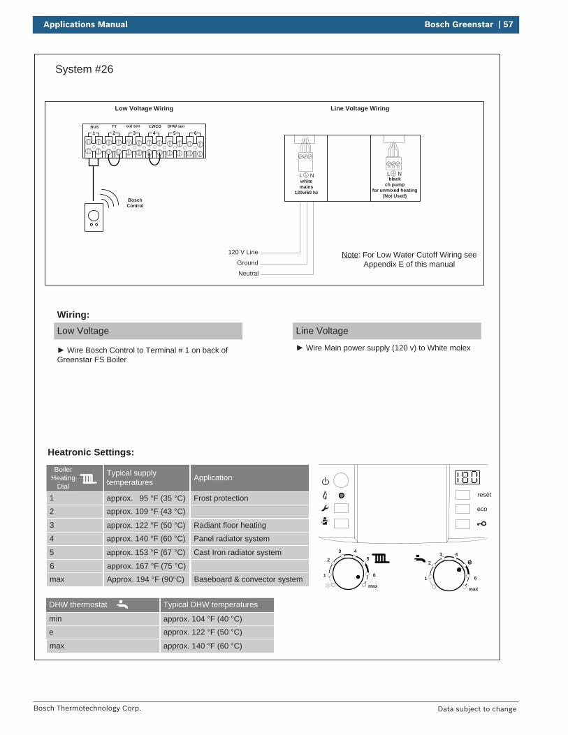
Applications Manual Bosch Greenstar | 57
Bosch Thermotechnology Corp. Data subject to change
System #26
BUS TT out sen LWCO DHW sen
1 2 3 4 5 6
reset
eco
1
2
3 45
6
max1
2
3 4
e
6
max
DHW thermostat
min
e
max
Typical DHW temperatures
approx. 104 °F (40 °C)
approx. 122 °F (50 °C)
approx. 140 °F (60 °C)
Boiler Heating
Dial
1
2
3
Typical supply temperatures
approx. 95 °F (35 °C)
approx. 109 °F (43 °C)
approx. 122 °F (50 °C)
4
5
6
approx. 140 °F (60 °C)
approx. 153 °F (67 °C)
approx. 167 °F (75 °C)
max Approx. 194 °F (90°C)
Application
Frost protection
Radiant floor heating
Panel radiator system
Cast Iron radiator system
Baseboard & convector system
Neutral
120 V Line
Ground
Low Voltage Wiring Line Voltage Wiring
Heatronic Settings:
Low Voltage
Wire Bosch Control to Terminal # 1 on back of Greenstar FS Boiler
Wiring:Line Voltage
Wire Main power supply (120 v) to White molex
L Nblack
ch pump for unmixed heating
(Not Used)
L Nwhitemains
120v/60 hz
Note: For Low Water Cutoff Wiring see Appendix E of this manual
BoschControl
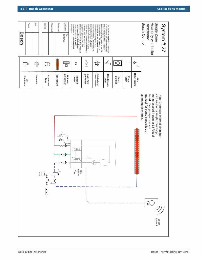
58 | Bosch Greenstar Applications Manual
Bosch Thermotechnology Corp.Data subject to change
Bosch
State
Bases
No.
.
Changed
Released
Created
TK02/20/15
Baseboard
Expansion Tank
Auto-Fill
Air
Eliminator
Isolation valve
Back-flow
preventer
Relief valve &
pressure gauge
Condensate
drain
Outdoor
air sensor
Bosch
Control
PurgeD
rain
DIS
CLA
IME
R: A
pplication drawings
in this manual are conceptual only
and do not purport to address all design, installation, code, or safety considerations. The diagram
s in this m
anual are for reference use by code officials, designers and licensed installers. It is expected that installers have adequate know
ledge of national and local codes, as w
ell as accepted industry practices, and are trained on equipm
ent, procedures, and applications involved. D
rawings are
not to scale. Refer to the boiler,
control and module installer
manuals for additional detailed
information.
Gas
Supply
PRV
Relief piping
Note:G
reenstar Internal circulator can support a single zone loop not to exceed 4 gpm
at 12 feet of head. S
ee pump curves in
manual for pum
p capacities at alternate flow
rates.
Single Zone
Heat only w
all boilerB
aseboardB
osch Control
Bosch
Control
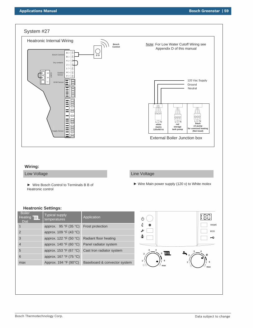
Applications Manual Bosch Greenstar | 59
Bosch Thermotechnology Corp. Data subject to change
System #27
reset
eco
1
2
3 45
6
max1
2
3 4
e
6
max
Boiler Heating
Dial1
2
3
Typical supply temperatures
approx. 95 °F (35 °C)approx. 109 °F (43 °C)
approx. 122 °F (50 °C)
4
5
6
approx. 140 °F (60 °C)
approx. 153 °F (67 °C)
approx. 167 °F (75 °C)
max Approx. 194 °F (90°C)
Application
Frost protection
Radiant floor heating
Panel radiator system
Cast Iron radiator system
Baseboard & convector system
Low Voltage
Wiring:Line Voltage
Wire Bosch Control to Terminals B B of Heatronic control
Wire Main power supply (120 v) to White molex
Heatronic Settings:
Heatronic Internal Wiring
B
B
4
2
1
A
F
97
8 LWC
O
Supply Sensor
DHW Sensor
Dry contacts
Bosch Controls
Outdoor Sensor
External Boiler Junction box
120 Vac SupplyGroundNeutral
L Nred
storagetank pump
L Nblack
ch pump for unmixed heating
(Not Used)
L Nwhitemains
120v/60 hz
Note: For Low Water Cutoff Wiring see Appendix D of this manual
BoschControl
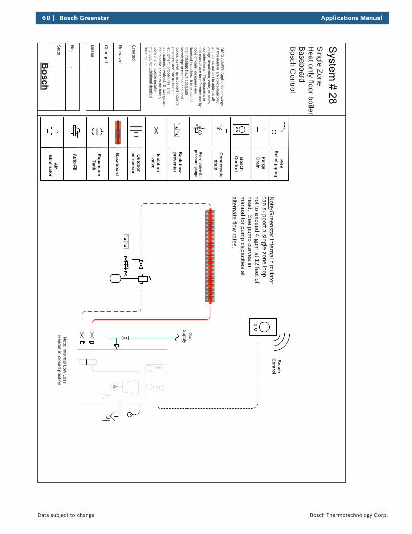
60 | Bosch Greenstar Applications Manual
Bosch Thermotechnology Corp.Data subject to change
Bosch
State
Bases
No.
.
Changed
Released
Created
Baseboard
Expansion Tank
Auto-Fill
Air
Eliminator
Isolation valve
Back-flow
preventer
Relief valve &
pressure gauge
Condensate
drain
Outdoor
air sensor
Bosch
Control
Purge D
rain
DIS
CLA
IME
R: A
pplication drawings
in this manual are conceptual only
and do not purport to address all design, installation, code, or safety considerations. The diagram
s in this m
anual are for reference use by code officials, designers and licensed installers. It is expected that installers have adequate know
ledge of national and local codes, as w
ell as accepted industry practices, and are trained on equipm
ent, procedures, and applications involved. D
rawings are
not to scale. Refer to the boiler,
control and module installer
manuals for additional detailed
information.
Gas
Supply
PRV
Relief piping
Note: Internal Low
Loss H
eader in closed position
Note:G
reenstar Internal circulator can support a single zone loop not to exceed 4 gpm
at 12 feet of head. S
ee pump curves in
manual for pum
p capacities at alternate flow
rates.
Single Zone
Heat only floor boiler
Baseboard
Bosch C
ontrol
Bosch
Control
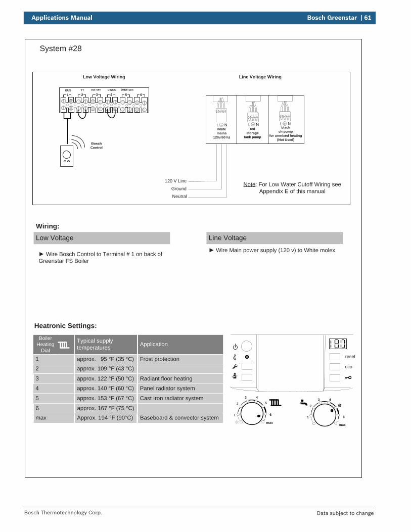
Applications Manual Bosch Greenstar | 61
Bosch Thermotechnology Corp. Data subject to change
System #28
BUS TT out sen LWCO DHW sen
1 2 3 4 5 6
reset
eco
1
2
3 45
6
max1
2
3 4
e
6
max
Boiler Heating
Dial
1
2
3
Typical supply temperatures
approx. 95 °F (35 °C)
approx. 109 °F (43 °C)
approx. 122 °F (50 °C)
4
5
6
approx. 140 °F (60 °C)
approx. 153 °F (67 °C)
approx. 167 °F (75 °C)
max Approx. 194 °F (90°C)
Application
Frost protection
Radiant floor heating
Panel radiator system
Cast Iron radiator system
Baseboard & convector system
Neutral
120 V Line
Ground
Low Voltage Wiring Line Voltage Wiring
Heatronic Settings:
Low Voltage
Wiring:Line Voltage
Wire Main power supply (120 v) to White molex Wire Bosch Control to Terminal # 1 on back of
Greenstar FS Boiler
L Nred
storagetank pump
L Nblack
ch pump for unmixed heating
(Not Used)
L Nwhitemains
120v/60 hz
Note: For Low Water Cutoff Wiring see Appendix E of this manual
BoschControl
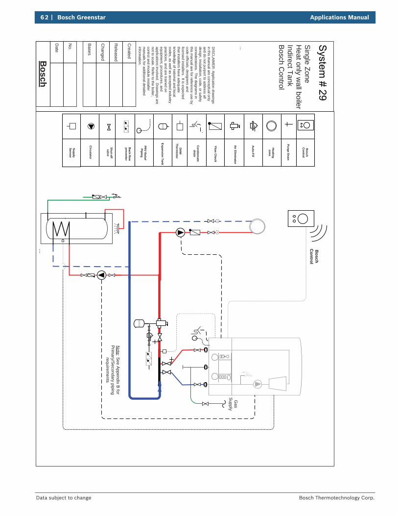
62 | Bosch Greenstar Applications Manual
Bosch Thermotechnology Corp.Data subject to change
Bosch
Date
...
Bases
No.
Changed
Released
Created
...
Expansion Tank
Auto-Fill
Air Elim
inator
Shut-off valve
Back-flow
preventer
PRV R
eliefPiping
Condensate
drain
Flow C
heck
Heatingzone
Circulator
Purge Drain
DIS
CLA
IME
R: A
pplication drawings
in this manual are conceptual only
and do not purport to address all design, installation, code, or safety considerations. The diagram
s in this m
anual are for reference use by code officials, designers and licensed installers. It is expected that installers have adequate know
ledge of national and local codes, as w
ell as accepted industry practices, and are trained on equipm
ent, procedures, and applications involved. D
rawings are
not to scale. Refer to the boiler,
control and module installer
manuals for additional detailed
information.
TT
SupplySensor
Note: S
ee Appendix B
for Prim
ary/Secondary piping
requirements
Bosch
Control
Gas
Supply
Single Zone
Heat only w
all boilerIndirect TankB
osch Control
Bosch
Control
DH
WTherm
istor
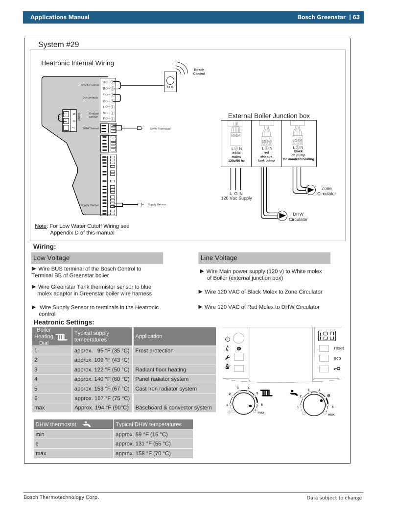
Applications Manual Bosch Greenstar | 63
Bosch Thermotechnology Corp. Data subject to change
System #29
reset
eco
1
2
3 45
6
max1
2
3 4
e
6
max
Boiler Heating
Dial1
2
3
Typical supply temperatures
approx. 95 °F (35 °C)
approx. 109 °F (43 °C)
approx. 122 °F (50 °C)
4
5
6
approx. 140 °F (60 °C)
approx. 153 °F (67 °C)
approx. 167 °F (75 °C)
max Approx. 194 °F (90°C)
Application
Frost protection
Radiant floor heating
Panel radiator system
Cast Iron radiator system
Baseboard & convector system
Heatronic Settings:
Low Voltage
Wiring:Line Voltage
Heatronic Internal Wiring
L NG
External Boiler Junction box
120 Vac Supply
B
B
4
2
1
A
F
97
8 LWC
O
Supply Sensor
DHW Sensor
Dry contacts
Bosch Controls
Outdoor Sensor
Wire BUS terminal of the Bosch Control to Terminal BB of Greenstar boiler
Wire Main power supply (120 v) to White molex of Boiler (external junction box)
Wire 120 VAC of Black Molex to Zone Circulator
Wire Supply Sensor to terminals in the Heatronic control
DHW Thermistor
Wire Greenstar Tank thermistor sensor to blue molex adaptor in Greenstar boiler wire harness
DHWCirculator
Wire 120 VAC of Red Molex to DHW Circulator
L Nred
storagetank pump
L Nblack
ch pump for unmixed heating
L Nwhitemains
120v/60 hz
Note: For Low Water Cutoff Wiring see Appendix D of this manual
Supply Sensor
DHW thermostat
min
e
max
Typical DHW temperatures
approx. 59 °F (15 °C)
approx. 131 °F (55 °C)
approx. 158 °F (70 °C)
BoschControl
ZoneCirculator
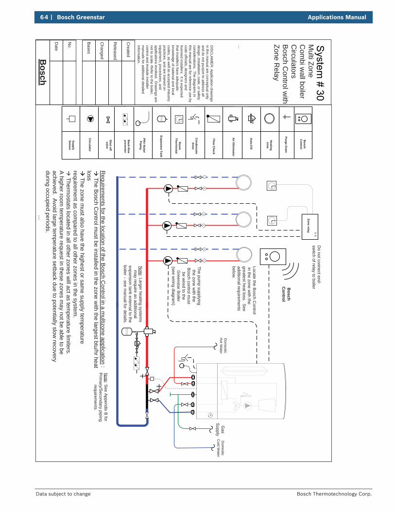
64 | Bosch Greenstar Applications Manual
Bosch Thermotechnology Corp.Data subject to change
Bosch
Date
...
Bases
No.
Changed
Released
Created
...
Expansion Tank
Auto-Fill
Air Elim
inator
Shut-off valve
Back-flow
preventer
PRV R
eliefPiping
Condensate
drain
Room
Therm
ostat
Flow C
heck
Heatingzone
Circulator
Purge Drain
DIS
CLA
IME
R: A
pplication drawings
in this manual are conceptual only
and do not purport to address all design, installation, code, or safety considerations. The diagram
s in this m
anual are for reference use by code officials, designers and licensed installers. It is expected that installers have adequate know
ledge of national and local codes, as w
ell as accepted industry practices, and are trained on equipm
ent, procedures, and applications involved. D
rawings are
not to scale. Refer to the boiler,
control and module installer
manuals for additional detailed
information.
TT
TT
TT
Note: Larger heating system
s m
ay require an additional expansion tank external to the boiler – see m
anual for details.
Dom
esticC
old Water
Dom
esticH
ot Water
Gas
Supply
Bosch
Control
SupplySensor
Note: S
ee Appendix B
for Prim
ary/Secondary piping
requirements
Multi Zone
Com
bi wall boiler
Circulators
Bosch C
ontrol with
Zone Relay
Bosch
Control
Zone relay X XD
o not connect end-sw
itch of relay to boiler
Locate the Bosch C
ontrol in the zone w
ith the greatest heat loss. See additional requirem
ents below
.
Requirem
ents for the location of the Bosch C
ontrol in a multizone application
: The B
osch Control m
ust be installed in the zone with the largest btu/hr heat
loss The zone m
ust also have the highest or same supply tem
perature requirem
ent as compared to all other zones in the system
. Therm
ostats located in all other zones will act as tem
perature limiters.
A higher room
temperature request in these zones m
ay not be able to be achieved. A
void large temperature setback due to potentially slow
recovery during occupied periods.
The pump supplying
the zone with the
Bosch control must
be wired to the
Greenstar B
oiler (see w
iring diagram)
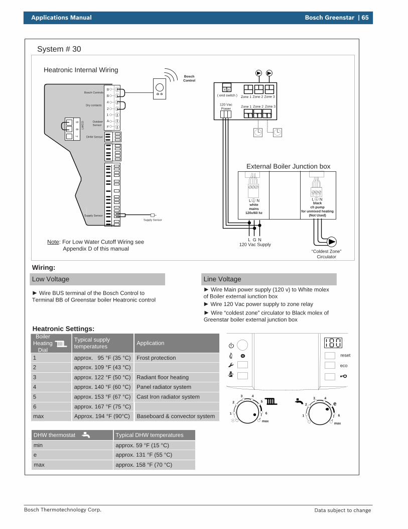
Applications Manual Bosch Greenstar | 65
Bosch Thermotechnology Corp. Data subject to change
System # 30
reset
eco
1
2
3 45
6
max1
2
3 4
e
6
max
Boiler Heating
Dial1
2
3
Typical supply temperatures
approx. 95 °F (35 °C)
approx. 109 °F (43 °C)
approx. 122 °F (50 °C)
4
5
6
approx. 140 °F (60 °C)
approx. 153 °F (67 °C)
approx. 167 °F (75 °C)
max Approx. 194 °F (90°C)
Application
Frost protection
Radiant floor heating
Panel radiator system
Cast Iron radiator system
Baseboard & convector system
Heatronic Settings:
Low Voltage
Wire BUS terminal of the Bosch Control to Terminal BB of Greenstar boiler Heatronic control
Wiring:Line Voltage
Wire Main power supply (120 v) to White molex of Boiler external junction box
Heatronic Internal Wiring
B
B
4
2
1
A
F
97
8 LWC
O
Supply Sensor
DHW Sensor
Dry contacts
Bosch Controls
Outdoor Sensor
Supply Sensor
( end switch )
T TT TT T
Zone 3Zone 1 Zone 2
Zone 3Zone 1 Zone 2
L NG
XX
External Boiler Junction box
120 Vac Supply
120 VacPower
Wire 120 Vac power supply to zone relay
L Nblack
ch pump for unmixed heating
(Not Used)
L Nwhitemains
120v/60 hz
Note: For Low Water Cutoff Wiring see Appendix D of this manual
DHW thermostat
min
e
max
Typical DHW temperatures
approx. 59 °F (15 °C)
approx. 131 °F (55 °C)
approx. 158 °F (70 °C)
“Coldest Zone” Circulator
BoschControl
Wire “coldest zone” circulator to Black molex of Greenstar boiler external junction box
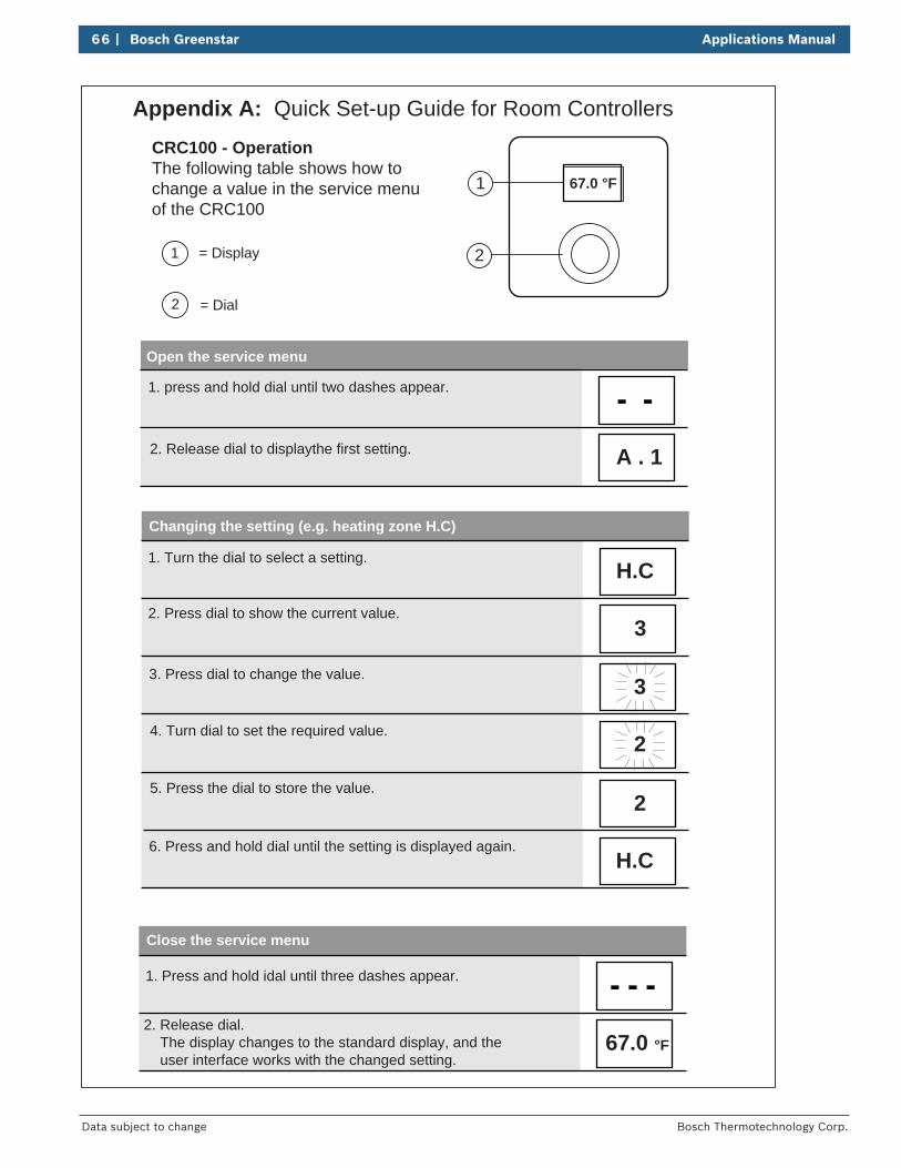
66 | Bosch Greenstar Applications Manual
Bosch Thermotechnology Corp.Data subject to change
CRC100 - OperationThe following table shows how to change a value in the service menu of the CRC100
Close the service menu
Changing the setting (e.g. heating zone H.C)
Open the service menu
1. press and hold dial until two dashes appear.
2. Release dial to displaythe first setting.
1. Turn the dial to select a setting.
2. Press dial to show the current value.
3. Press dial to change the value.
4. Turn dial to set the required value.
5. Press the dial to store the value.
6. Press and hold dial until the setting is displayed again.
1. Press and hold idal until three dashes appear.
2. Release dial. The display changes to the standard display, and the user interface works with the changed setting.
67.0 °F
H.C
2
2
3
3
H.C
A . 1
1 = Display
2 = Dial
67.0 °F1
2
Appendix A: Quick Set-up Guide for Room Controllers
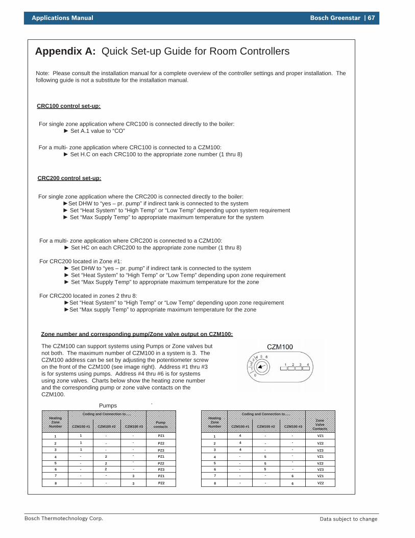
Applications Manual Bosch Greenstar | 67
Bosch Thermotechnology Corp. Data subject to change
Appendix A: Quick Set-up Guide for Room Controllers
CRC100 control set-up:
For single zone application where CRC100 is connected directly to the boiler: Set A.1 value to “CO”
Note: Please consult the installation manual for a complete overview of the controller settings and proper installation. The following guide is not a substitute for the installation manual.
For a multi- zone application where CRC100 is connected to a CZM100: Set H.C on each CRC100 to the appropriate zone number (1 thru 8)
CRC200 control set-up:
For single zone application where the CRC200 is connected directly to the boiler: Set DHW to “yes – pr. pump” if indirect tank is connected to the system Set “Heat System” to “High Temp” or “Low Temp” depending upon system requirement Set “Max Supply Temp” to appropriate maximum temperature for the system
For a multi- zone application where CRC200 is connected to a CZM100: Set HC on each CRC200 to the appropriate zone number (1 thru 8)
For CRC200 located in Zone #1: Set DHW to “yes – pr. pump” if indirect tank is connected to the system Set “Heat System” to “High Temp” or “Low Temp” depending upon zone requirement Set “Max Supply Temp” to appropriate maximum temperature for the zone
For CRC200 located in zones 2 thru 8:Set “Heat System” to “High Temp” or “Low Temp” depending upon zone requirementSet “Max supply Temp” to appropriate maximum temperature for the zone
Coding and Connection to…..
CZM100 #1 CZM100 #2 CZM100 #3
Heating Zone
NumberPump
contacts
1
2
3
4
5
6
7
8
1
1
1
2
22
3
3
-
-
-
-
-
-
-
-
-
-
-
-
-
-
- PZ1
-
-
PZ2
PZ3
PZ1
PZ2
PZ3
PZ1
PZ2
Coding and Connection to…..
CZM100 #1 CZM100 #2 CZM100 #3
Heating Zone
NumberZoneValve
Contacts
1
2
3
4
5
6
7
8
4
4
4
5
55
6
6
-
-
-
-
-
-
-
-
-
-
-
-
-
- VZ1
-
-
VZ2
VZ3
VZ1
VZ2
VZ3
VZ1
VZ2
Zone number and corresponding pump/Zone valve output on CZM100:
The CZM100 can support systems using Pumps or Zone valves but not both. The maximum number of CZM100 in a system is 3. The CZM100 address can be set by adjusting the potentiometer screw on the front of the CZM100 (see image right). Address #1 thru #3 is for systems using pumps. Address #4 thru #6 is for systems using zone valves. Charts below show the heating zone number and the corresponding pump or zone valve contacts on the CZM100.
Pumps
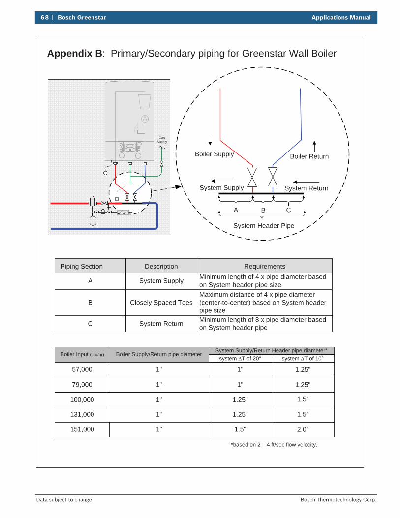
68 | Bosch Greenstar Applications Manual
Bosch Thermotechnology Corp.Data subject to change
GasSupply
A B C
System ReturnSystem Supply
Boiler ReturnBoiler Supply
Piping Section Description Requirements
A System Supply Minimum length of 4 x pipe diameter based on System header pipe size
B Closely Spaced TeesMaximum distance of 4 x pipe diameter (center-to-center) based on System header pipe size
C System Return Minimum length of 8 x pipe diameter based on System header pipe
Boiler Input (btu/hr) Boiler Supply/Return pipe diameterSystem Supply/Return Header pipe diameter*
57,000 1" 1"
79,000 1" 1"
100,000 1" 1.25"
131,000 1" 1.25"
151,000 1" 1.5"
System Header Pipe
*based on 2 – 4 ft/sec flow velocity.
system T of 20° system T of 10°
1.25"
1.25"
1.5"
1.5"
2.0"
Appendix B: Primary/Secondary piping for Greenstar Wall Boiler
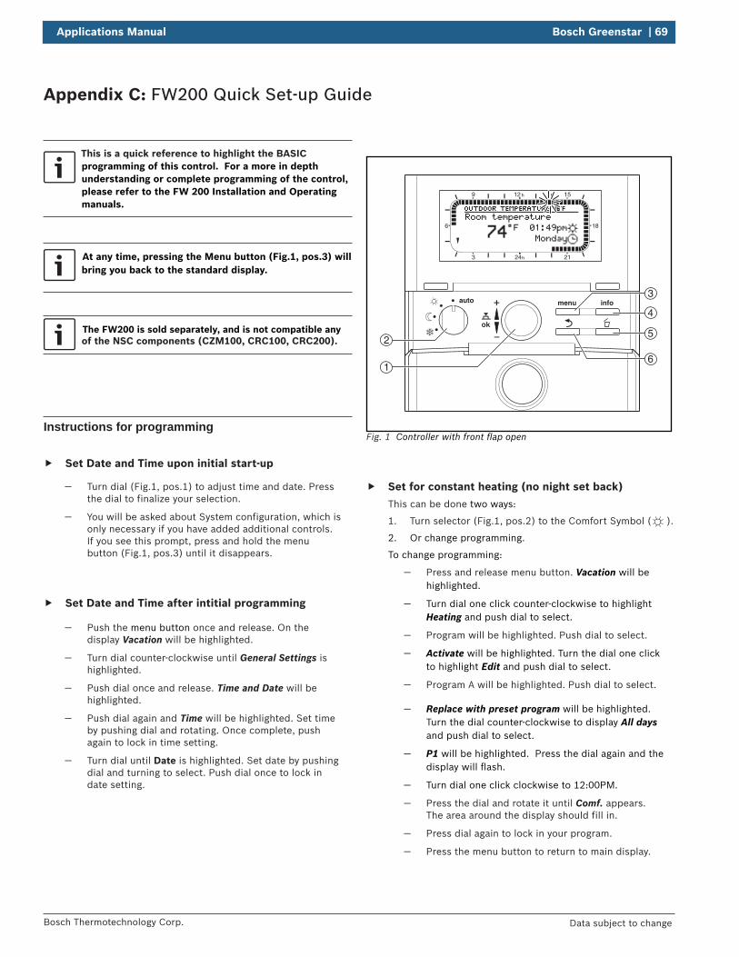
Applications Manual Bosch Greenstar | 69
Bosch Thermotechnology Corp. Data subject to change
Appendix C: FW200 Quick Set-up Guide
This is a quick reference to highlight the BASIC programming of this control. For a more in depth understanding or complete programming of the control, please refer to the FW 200 Installation and Operating manuals.
At any time, pressing the Menu button (Fig.1, pos.3) will bring you back to the standard display.
The FW200 is sold separately, and is not compatible any of the NSC components (CZM100, CRC100, CRC200).
Instructions for programming
Set Date and Time upon initial start-up
— Turn dial (Fig.1, pos.1) to adjust time and date. Press the dial to finalize your selection.
— You will be asked about System configuration, which is only necessary if you have added additional controls. If you see this prompt, press and hold the menu button (Fig.1, pos.3) until it disappears.
Set Date and Time after intitial programming
— Push the menu button once and release. On the display Vacation will be highlighted.
— Turn dial counter-clockwise until General Settings is highlighted.
— Push dial once and release. Time and Date will be highlighted.
— Push dial again and Time will be highlighted. Set time by pushing dial and rotating. Once complete, push again to lock in time setting.
— Turn dial until Date is highlighted. Set date by pushing dial and turning to select. Push dial once to lock in date setting.
1
2
3
4
5
6
9 12 h 15
18
2124h3
6
Fig. 1 Controller with front fl ap open
Set for constant heating (no night set back) This can be done two ways:
1. Turn selector (Fig.1, pos.2) to the Comfort Symbol ( ).
2. Or change programming.
To change programming:
— Press and release menu button. Vacation will be highlighted.
— Turn dial one click counter-clockwise to highlight Heating and push dial to select.
— Program will be highlighted. Push dial to select.
— Activate will be highlighted. Turn the dial one click to highlight Edit and push dial to select.
— Program A will be highlighted. Push dial to select.
— Replace with preset program will be highlighted. Turn the dial counter-clockwise to display All days and push dial to select.
— P1 will be highlighted. Press the dial again and the display will fl ash.
— Turn dial one click clockwise to 12:00PM.
— Press the dial and rotate it until Comf. appears. The area around the display should fill in.
— Press dial again to lock in your program.
— Press the menu button to return to main display.
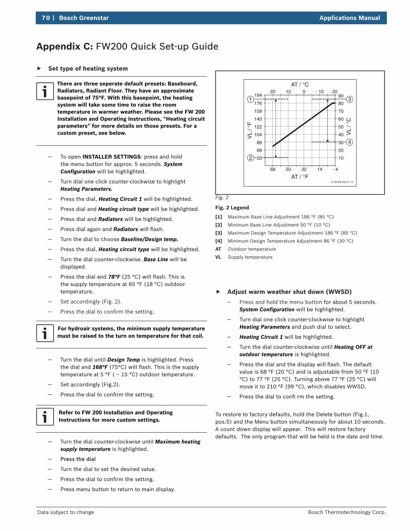
70 | Bosch Greenstar Applications Manual
Bosch Thermotechnology Corp.Data subject to change
Appendix C: FW200 Quick Set-up Guide
Set type of heating system
There are three seperate default presets: Baseboard, Radiators, Radiant Floor. They have an approximate basepoint of 75°F. With this basepoint, the heating system will take some time to raise the room temperature in warmer weather. Please see the FW 200Installation and Operating Instructions, “Heating circuitparameters” for more details on those presets. For a custom preset, see below.
— To open INSTALLER SETTINGS: press and hold the menu button for approx. 5 seconds. System Confi guration will be highlighted.
— Turn dial one click counter-clockwise to highlight Heating Parameters.
— Press the dial, Heating Circuit 1 will be highlighted.
— Press dial and Heating circuit type will be highlighted.
— Press dial and Radiators will be highlighted.
— Press dial again and Radiators will fl ash.
— Turn the dial to choose Baseline/Design temp.
— Press the dial, Heating circuit type will be highlighted.
— Turn the dial counter-clockwise. Base Line will be displayed.
— Press the dial and 78°F (25 °C) will fl ash. This is the supply temperature at 65 °F (18 °C) outdoor temperature.
— Set accordingly (Fig. 2).
— Press the dial to confi rm the setting.
For hydroair systems, the minimum supply temperature must be raised to the turn on temperature for that coil.
— Turn the dial until Design Temp is highlighted. Press the dial and 168°F (75°C) will fl ash. This is the supply temperature at 5 °F ( – 15 °C) outdoor temperature.
— Set accordingly (Fig.2).
— Press the dial to confi rm the setting.
Refer to FW 200 Installation and Operating Instructions for more custom settings.
— Turn the dial counter-clockwise until Maximum heating
supply temperature is highlighted.
— Press the dial
— Turn the dial to set the desired value.
— Press the dial to confi rm the setting.
— Press menu button to return to main display.
6 720 806 992-07.1O
68 50 32 14 - 4
68
86
104
122
140
158
176
1941 3
4
2 50
VL
/ °F
AT / °F
20 10 0 - 10 - 20
20
30
40
50
60
70
80
90
10
VL
/ °C
AT / °C
Fig. 2
Fig. 2 Legend
[1] Maximum Base Line Adjustment 186 °F (85 °C)
[2] Minimum Base Line Adjustment 50 °F (10 °C)
[3] Maximum Design Temperature Adjustment 186 °F (85 °C)
[4] Minimum Design Temperature Adjustment 86 °F (30 °C)
AT Outdoor temperature
VL Supply temperature
Adjust warm weather shut down (WWSD)
— Press and hold the menu button for about 5 seconds. System Confi guration will be highlighted.
— Turn dial one click counter-clockwise to highlight Heating Parameters and push dial to select.
— Heating Circuit 1 will be highlighted.
— Turn the dial counter-clockwise until Heating OFF at outdoor temperature is highlighted.
— Press the dial and the display will fl ash. The default value is 68 °F (20 °C) and is adjustable from 50 °F (10 °C) to 77 °F (25 °C). Turning above 77 °F (25 °C) will move it to 210 °F (99 °C), which disables WWSD.
— Press the dial to confi rm the setting.
To restore to factory defaults, hold the Delete button (Fig.1, pos.5) and the Menu button simultaneously for about 10 seconds. A count down display will appear. This will restore factory defaults. The only program that will be held is the date and time.
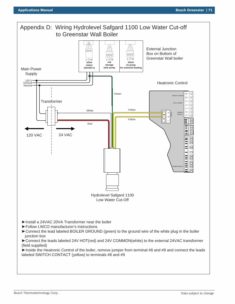
Applications Manual Bosch Greenstar | 71
Bosch Thermotechnology Corp. Data subject to change
B
B
4
2
1
A
F
97
8 LWC
O
Supply Sensor
Dry contacts
Bosch Controls
Outdoor Sensor
120 VAC 24 VAC
L Nred
storagetank pump
L Nblack
ch pump for unmixed heating
L Nwhitemains
120v/60 hz
GroundNeutral
120 V
Transformer
External Junction Box on Bottom of Greenstar Wall boiler
Heatronic Control
Hydrolevel Safgard 1100 Low Water Cut-Off
Install a 24VAC 20VA Transformer near the boilerFollow LWCO manufacturer’s instructionsConnect the lead labeled BOILER GROUND (green) to the ground wire of the white plug in the boiler
junction boxConnect the leads labeled 24V HOT(red) and 24V COMMON(white) to the external 24VAC transformer
(field supplied)Inside the Heatronic Control of the boiler, remove jumper from terminal #8 and #9 and connect the leads
labeled SWITCH CONTACT (yellow) to terminals #8 and #9
Appendix D: Wiring Hydrolevel Safgard 1100 Low Water Cut-off to Greenstar Wall Boiler
Main Power Supply
Yellow
Yellow
Green
White
Red
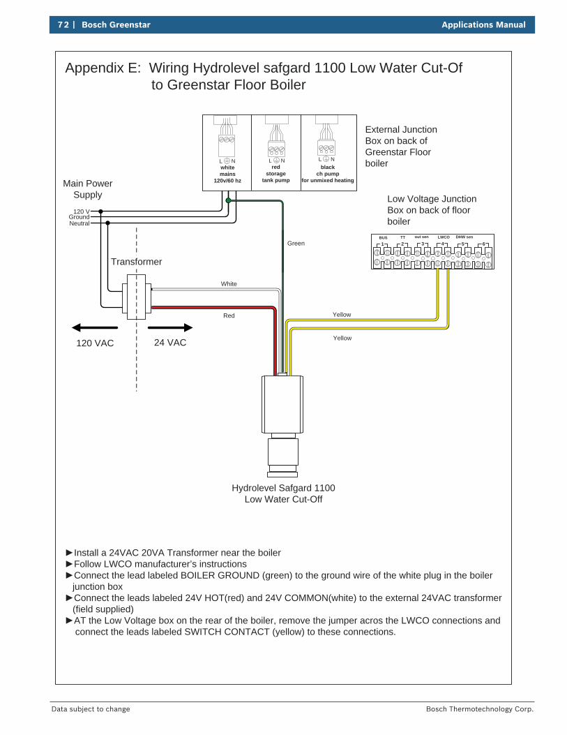
72 | Bosch Greenstar Applications Manual
Bosch Thermotechnology Corp.Data subject to change
120 VAC 24 VAC
L Nred
storagetank pump
L Nblack
ch pump for unmixed heating
L Nwhitemains
120v/60 hz
GroundNeutral
120 V
Transformer
External Junction Box on back of Greenstar Floor boiler
Low Voltage Junction Box on back of floor boiler
Hydrolevel Safgard 1100 Low Water Cut-Off
Install a 24VAC 20VA Transformer near the boilerFollow LWCO manufacturer’s instructionsConnect the lead labeled BOILER GROUND (green) to the ground wire of the white plug in the boiler
junction boxConnect the leads labeled 24V HOT(red) and 24V COMMON(white) to the external 24VAC transformer
(field supplied)AT the Low Voltage box on the rear of the boiler, remove the jumper acros the LWCO connections and
connect the leads labeled SWITCH CONTACT (yellow) to these connections.
Appendix E: Wiring Hydrolevel safgard 1100 Low Water Cut-Of to Greenstar Floor Boiler
Main Power Supply
Yellow
Yellow
Green
White
Red
BUS TT out sen LWCO DHW sen
1 2 3 4 5 6

Applications Manual Bosch Greenstar | 73
Bosch Thermotechnology Corp. Data subject to change
74 | Bosch Greenstar Applications Manual
Bosch Thermotechnology Corp.Data subject to change
Applications Manual Bosch Greenstar | 75
Bosch Thermotechnology Corp. Data subject to change
United States and Canada
Bosch Thermotechnology Corp.50 Wentworth AvenueLondonderry, NH 03053
Tel: 866-642-3198Fax: 603-965-7581www.boschheatingandcooling.com
BTC 436001101 D / 04.2017