Embed Size (px)
Citation preview
Transp Porous MedDOI 10.1007/s11242-014-0292-9
Gas Capture in a Cavity with Porous Walls
Michael Conrath · Yulia Smiyukha
Received: 16 January 2013 / Accepted: 6 February 2014© Springer Science+Business Media Dordrecht 2014
Abstract A configuration like an upside-down bell made of porous material is consideredwhich is initially dry but then subjected to a rising pool of liquid. As liquid touches the rim ofthe bell, capillary transport is initiated. Starting with a vertical wicking phase, the imbibingliquid will eventually reach the ceiling of the bell and switch over to horizonal wicking. Atthe end of the horizontal wicking, the cavity inside the porous bell is enclosed by liquidand the gas inside it is captured. We present a model to describe the capillary transport inthe bell for both Cartesian and cylindrical geometry. As far as possible, we derive analyticalsolutions to the normalized differential equations that describe the problem. Beyond analyticalsolutions, we use Runge–Kutta shooting method to obtain numerical results. We calculatethe normalized closure time to capture the gas, the amount of captured gas, and reflect on thepressure development in the gas chamber.
Keywords Porous cavity · Capillary transport · Wicking process · Gas trapping ·Runge–Kutta
Nomenclature
a Wicking constant, relates surface pressure to viscous stress (m2/s)b Wicking constant, relates hydrostatic pressure to viscous stress (m2/s)Boθ Type of Bond number, relates hydrostatic to surface pressureBoc Critical Bond number corresponding to X0
d Thickness of the porous walls of the cavity (m)Fo Forchheimer number, relates convective to viscous pressure loss
Electronic supplementary material The online version of this article (doi:10.1007/s11242-014-0292-9)contains supplementary material, which is available to authorized users.
M. Conrath (B) · Y. SmiyukhaCenter of Applied Space Technology and Microgravity (ZARM),University of Bremen, Am Fallturm 01 , 28359 Bremen, Germanye-mail: [email protected]
123
M. Conrath, Y. Smiyukha
g Earth gravity constant, g = 9.81 m/s2
H Height of the porous walls of the cavity (m)�h Hydrostatic height between wicking front and liquid reservoir (m)K Hydraulic permeability of the porous medium (m2)L Combined vertical and horizontal length (m)Lσ Capillary length (m)�p Pressure difference between front and back side of the cavity ceiling (Pa)Q Liquid flow rate (m3/s)r Radial coordinate (m)r∗ Dimensionless radial position of the wicking frontR Radial position of the wicking front (m)R0 Radius of the porous walls of the cavity (m)Rs Static radius of the pores (m)S Saturation of the pores with liquid, between 0 and 1t Time (s)t∗ Dimensionless timetd Delay time until liquid contacts the cavity (s)u Rising velocity of the liquid (m/s)v⊥ Velocity of gas cross flow through the cavity ceiling (m/s)�Vjump Volume between outer and inner edge profile at liquid contact (m3)W Width of the porous walls of the cavity (Cartesian) (m)x Horizontal coordinate (Cartesian) (m)x∗ Dimensionless horizontal position of the wicking frontX Horizontal position of the wicking front (m)X0 Aspect ratio, wicking height to total wicking lengthz Vertical coordinate (m)z∗ Dimensionless vertical position of the wicking frontZ Vertical position of the wicking front (m)�z Height difference due to wall adhesion (m)φ Porosity of the cavity� Aspect ratio, radial to total wicking lengthμ Dynamic viscosity of the liquid (kg/(m s))θ Contact angleρ Liquid density (kg/m3)σ Surface tension (N/m)�u Dimensionless parameter, relating wicking time to pool rise time�c critical �u corresponding to X0
1 Introduction
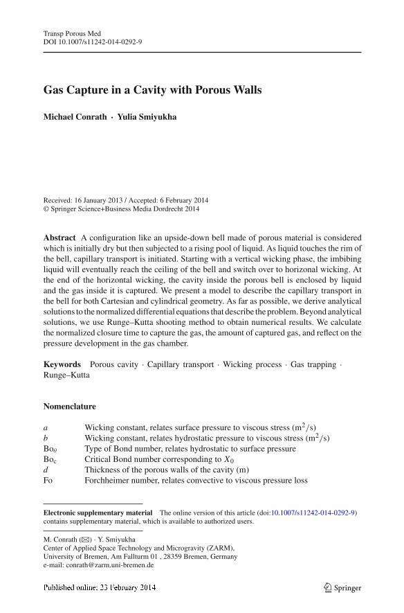
Figure 1 shows the subject of the present study. Confined in a tube, a porous structure shapedlike an upside-down beaker is submitted to a rising pool of liquid. When the liquid rises nottoo fast, a pocket of gas is captured in the cavity. This kind of problem occurs, for example,at flood events when water rises in soil. Such flooding events occur regularly at tidal coastareas, seasonally at river banks and floodplains, or simply as a result of heavy rain. Theyaffect the function of plant roots, the survival of subterranean mammals that live in self-excavated tunnels and burrows, and the vadose zone in general (Justin and Armstrong 1987;Hickman 1990; Maitland and Maitland 1994; Blom and Voeseneck 1996). Gas capture is also
123
Gas Capture in a Cavity
solid wall
porousmaterial
meniscus
rising liquid
gas
Fig. 1 Configuration to capture gas by capillary action. Suspended in a tube, an upside-down porous bell thatis initially dry is submitted to a rising liquid. As soon as liquid touches the porous media, it wicks into thepores and starts to saturate the media. During the wicking process, gas is pushed out of the cavity through theceiling causing a pressure drop. Eventually, the liquid encloses and captures a pocket of gas inside the cavity
of interest in subsoil irrigation (Barth 1999; Ben-Gal et al. 2004; Lazarovitch et al. 2005).Another catchword related to such kind of problems is the storage of carbon dioxide and othergases in sandy porous media (Wang et al. 1998; Suekane et al. 2010; Wildenschild et al. 2011;Zhou et al. 2011). Gas capture effects in porous media are also known from natural oil and gasexploitation (Bennion et al. 1994, 1996). Furthermore, it will appear when a porous structurewith cavity inside it is immersed in a liquid. The protection of waste dumps by capillarybarriers (Aubertin et al. 2009) belongs to that category. There is also a technical applicationto block liquid passage during gas venting. In fact, it is the latter application that served asmotivation here, see Conrath et al. (2013). That is because modern spacecraft use cryogenichydrogen and oxygen as liquid fuels (Dodge 2000; Jurn and Kudlac 2006). Therefore, theydo not only need to ensure that the liquid fuel is drawn bubble free from the tank (Kudlac andJurns 2006; Jurns and McQuillen 2008; Conrath and Dreyer 2012), but also a safety deviceto avoid the loss of fuel when gas is vented from the tanks for pressure regulation would bedesirable. The problem posed by the arrangement in Fig. 1 involves capillary transport tocapture the gas, gas compression, leakage flow, and eventually gas breakthrough. We presenta model to deal with these challenges. We identify the dimensionless parameters that definethe problem to derive solutions of general validity. Analytical and semi-analytical solutionsare provided for the closure time that it takes to trap the gas. Based on the time dependence ofthe gas capture process and the pressure drop caused by the gas cross flow through the beakersbottom, we reflect on the captured gas volume, its compression, the pressure developmentinside the gas chamber, leakage, and eventual gas breakthrough.
2 Problem Description
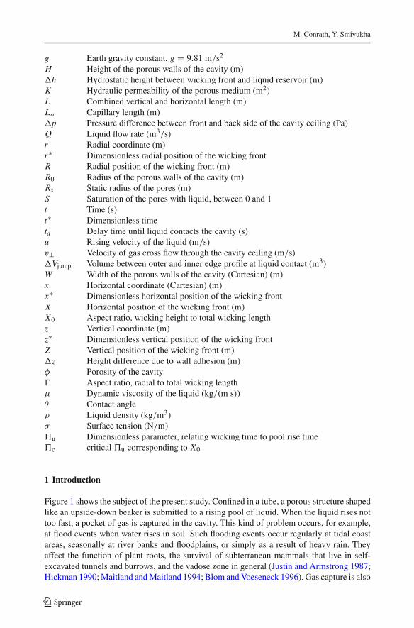
In more detail, the problem is outlined by Figs. 2 and 3. Figure 2 shows the properties anddimensions of the cavity with porous walls. We tackle both the mirror-symmetric Cartesianproblem as depicted in Fig. 2a and the axially symmetric cylindrical problem as depicted inFig. 2b. The dimensions of the upside-down porous beaker are defined by a vertical length L ,a width 2W (Cartesian) or a radius R0 (cylindrical), respectively, and a thickness d . Its porousproperties are porosity φ, hydraulic permeability, K and static radius Rs that determines thepull of the menisci in capillary transport.
Figure 3 shows the cavity at subsequent stages of the gas capture process. All the time,the upside-down beaker remains suspended in the tube, and the liquid moves upward with
123

M. Conrath, Y. Smiyukha
Fig. 2 Dimensions of the cavitywith porous walls amirror-symmetric Cartesian caseand b axially symmetriccylindrical case
H
0
d d
(a) (b)
φ , K, Rs
x
z z
r
2W + d2W 2R
2R + d
0
initial state verticalwicking
horizontalwicking
compression,leakage
breakthrough
trappedgas
p
gas
rising liquid
u
(a) (b) (c) (d) (e)
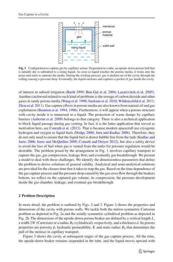
Fig. 3 Subsequent stages of the gas capture process. Starting with a dry cavity wall that faces a steadily risingliquid pool, capillary transport begins as soon as the liquid wets the pores of the cavity. When the capillarywicking front moves sufficiently faster than the liquid rises, the cavity will capture a portion of gas inside
a constant flow rate or a constant bulk velocity u, respectively. At the time t = 0, see Fig.3a, the liquid comes in contact with the pores of the cavity at its lower rim. Before that,the whole body of the porous cavity wall is assumed to be dry. Therefore, while the liquidpool moves steadily upward, a gas flow is forced through the ceiling of the cavity, causing across-flow pressure loss �p⊥. After first contact with the beaker, the liquid imbibes its poresleading to capillary rise also called vertical wicking as shown in Fig. 3b. When the verticalwicking velocity exceeds that of the steadily elevating liquid pool, the wicking front will beahead of the liquid pool level. Thus, it will reach the ceiling of the cavity before the pool doesand turn around the edge. Now comes the horizontal wicking phase as depicted by Fig. 3c.In the Cartesian case, one can think, for example, of a porous tunnel, in which the wickingfront has just changed its direction from vertical to horizontal, but the front length remainsunaltered. In the cylindrical case, however, we now have a radial inward wicking, and as thewicking front approaches the symmetry axis, its length decreases. In both cases, when thewicking front collapses at the center of the cavities ceiling, the cavity is closed. No more gascan escape now through unwetted pores, instead it is captured inside the cavity with porouswall. As the liquid pool rises further, see Fig. 3d, the trapped gas is compressed. And sois the liquid in the pores which is why it starts to leak along the vertical wall of the cavitythrough the ceiling. As the degree of compression increases, the pressure difference across
123
Gas Capture in a Cavity
the cavity ceiling eventually surpasses the bubble point threshold where gas is forced eveninto the wetted pores and breakthrough occurs, as is shown in Fig. 3e.
We will deal with these five stages of the process according to Fig. 3 now in more detail. Inregard to the motivation of this study, our considerations will extend not only to the terrestrialstandard case of gravity pointing downward with 1g = 9.81 m/s2, but also to the case ofweightlessness.
3 Governing Equations
3.1 Initial State
3.1.1 Saturation Conditions
We assume that the saturation S with liquid in the pores of the cavity is either S = 0 (dry) orS = 1 (wet). Until t = 0, the cavity is completely dry or not saturated, respectively. Duringvertical and horizontal wicking, the saturation at the wicking front jumps from S = 0 toS = 1. We suppose that there is no transition zone whatsoever.
3.1.2 Rising Liquid
Liquid properties The liquid has a surface tension σ , a dynamic viscosity μ, and a density ρ.It wets both the tube and the porous material of the cavity with the same static contact angleθ . The contact angle is known to vary when the contact line moves. It makes a differencewhether the contact line is pushed forward (steepens θ ) or pulled backward (flattens θ ), andalso how fast this happens, see de Gennes (1985). However, since we are mainly interested ina basic model of the gas capture process, we neglect both the dynamics of the contact angleand its hysteresis.
Wall adhesion The contact angle needs to be smaller than 90◦ in order to wet the pores, tomake the capture process possible at all.
θ < 90◦. (1)
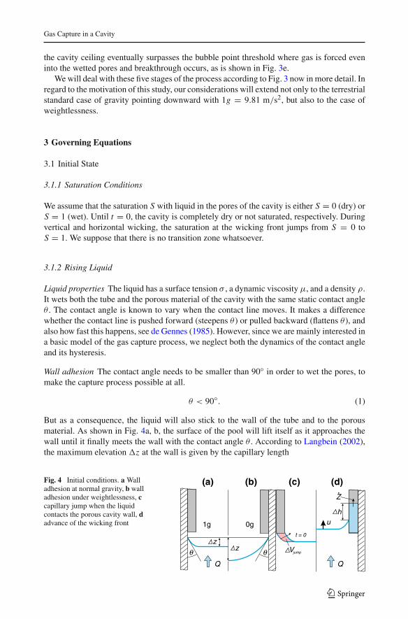
But as a consequence, the liquid will also stick to the wall of the tube and to the porousmaterial. As shown in Fig. 4a, b, the surface of the pool will lift itself as it approaches thewall until it finally meets the wall with the contact angle θ . According to Langbein (2002),the maximum elevation �z at the wall is given by the capillary length
Fig. 4 Initial conditions. a Walladhesion at normal gravity, b walladhesion under weightlessness, ccapillary jump when the liquidcontacts the porous cavity wall, dadvance of the wicking front
zjumpVθ θ
1g 0gt = 0
z
h
Q
u
Q
Z
(a) (b) (c) (d)
123
M. Conrath, Y. Smiyukha
Lσ =√
2σ
ρg(2)
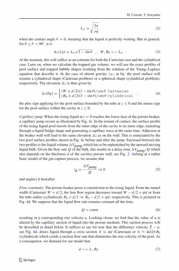
when the contact angle θ = 0, meaning that the liquid is perfectly wetting. But in general,for 0 ≤ θ < 90◦, it is
�z(1g) = Lσ
√1 − sin θ , W, R0 >> Lσ . (3)
At the moment, this will suffice as an estimate for both the Cartesian case and the cylindricalcase. Later on, when we calculate the trapped gas volume, we will use the exact profiles ofpool surface and trapped bubble shapes resulting from the solution of the Young–Laplaceequation that describe it. In the case of absent gravity, i.e., at 0g, the pool surface willassume a cylindrical shape (Cartesian problem) or a spherical shape (cylindrical problem),respectively. The elevation �z is then given by
�z(0g) ={
(W ± d/2)(1 − sin θ)/ cos θ Cartesian(R0 ± d/2)(1 − sin θ)/ cos θ cylindrical
, (4)
the plus sign applying for the pool surface bounded by the tube at z ≤ 0 and the minus signfor the pool surface within the cavity at z ≥ 0.
Capillary jump When the rising liquid at t = 0 reaches the lower face of the porous beaker,a capillary jump occurs as illustrated by Fig. 4c. In the instant of contact, the surface profileof the rising liquid pool travels from the outer edge of the cavity to its inner edge, transitingthrough a liquid bridge shape and generating a capillary wave at the same time. Adhesion atthe beaker wall will lead to the same elevation �z as on the wall. This is enunciated by thetwo pool surface profiles shown in Fig. 4c before and after the jump. Enclosed between thetwo profiles is the liquid volume �Vjump which has to be replenished by the upward movingliquid bulk. Given the flow rate Q of the bulk, this results in a delay time �Vjump/Q whichalso depends on the thickness d of the cavities porous wall, see Fig. 2. Aiming at a ratherbasic model of the gas capture process, we assume that
td = �VjumpQ
⇒ 0 (5)
and neglect it hereafter.
Flow continuity The porous beaker poses a constriction to the rising liquid. From the tunnelwidth (Cartesian) W + d/2, the free flow region decreases toward W − d/2 + φd or fromthe tube radius (cylindrical) R0 + d/2 ⇒ R0 − d/2 + φd , respectively. This is pictured inFig. 4d. We suppose that the liquid flow rate remains constant all the time,
Q = const (6)
resulting in a corresponding rise velocity u. Looking closer, we find that the value of u isaltered by the capillary suction of liquid into the porous medium. This suction process willbe described in detail below. It suffices to say for now that the difference velocity Z − u,see Fig. 4d, draws liquid through a cross section A ∝ φd (Cartesian) or A ≈ φd2π R0
(cylindrical) which yields a suction flow rate that diminishes the rise velocity of the pool. Asa consequence, we demand for our model that
d << L , R0 (7)
123
Gas Capture in a Cavity
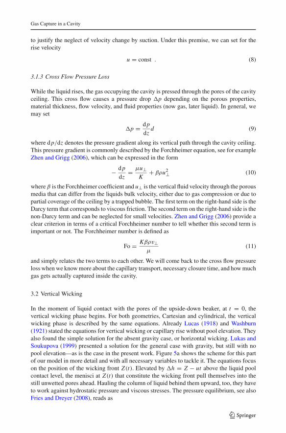
to justify the neglect of velocity change by suction. Under this premise, we can set for therise velocity
u = const . (8)
3.1.3 Cross Flow Pressure Loss
While the liquid rises, the gas occupying the cavity is pressed through the pores of the cavityceiling. This cross flow causes a pressure drop �p depending on the porous properties,material thickness, flow velocity, and fluid properties (now gas, later liquid). In general, wemay set
�p = d p
dzd (9)
where d p/dz denotes the pressure gradient along its vertical path through the cavity ceiling.This pressure gradient is commonly described by the Forchheimer equation, see for exampleZhen and Grigg (2006), which can be expressed in the form
− d p
dz= μu⊥
K+ βρu2⊥ (10)
where β is the Forchheimer coefficient and u⊥ is the vertical fluid velocity through the porousmedia that can differ from the liquids bulk velocity, either due to gas compression or due topartial coverage of the ceiling by a trapped bubble. The first term on the right-hand side is theDarcy term that corresponds to viscous friction. The second term on the right-hand side is thenon-Darcy term and can be neglected for small velocities. Zhen and Grigg (2006) provide aclear criterion in terms of a critical Forchheimer number to tell whether this second term isimportant or not. The Forchheimer number is defined as
Fo = Kβρv⊥μ
(11)
and simply relates the two terms to each other. We will come back to the cross flow pressureloss when we know more about the capillary transport, necessary closure time, and how muchgas gets actually captured inside the cavity.
3.2 Vertical Wicking
In the moment of liquid contact with the pores of the upside-down beaker, at t = 0, thevertical wicking phase begins. For both geometries, Cartesian and cylindrical, the verticalwicking phase is described by the same equations. Already Lucas (1918) and Washburn(1921) stated the equations for vertical wicking or capillary rise without pool elevation. Theyalso found the simple solution for the absent gravity case, or horizontal wicking. Lukas andSoukupova (1999) presented a solution for the general case with gravity, but still with nopool elevation—as is the case in the present work. Figure 5a shows the scheme for this partof our model in more detail and with all necessary variables to tackle it. The equations focuson the position of the wicking front Z(t). Elevated by �h = Z − ut above the liquid poolcontact level, the menisci at Z(t) that constitute the wicking front pull themselves into thestill unwetted pores ahead. Hauling the column of liquid behind them upward, too, they haveto work against hydrostatic pressure and viscous stresses. The pressure equilibrium, see alsoFries and Dreyer (2008), reads as
123
M. Conrath, Y. Smiyukha
u
X
z=0
uh=Z-ut
Z(t)Z
H
x=0X(t)
W
u
-R
H
r=0R(t)r=R0
R0
(a) (b) (c)
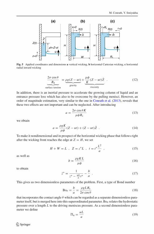
Fig. 5 Applied coordinates and dimensions a vertical wicking, b horizontal Cartesian wicking, c horizontalradial inward wicking
2σ cos θ
Rs︸ ︷︷ ︸surface tension
= ρg(Z − ut)︸ ︷︷ ︸gravity
+ μφ
K(Z − ut)Z︸ ︷︷ ︸viscosity
. (12)
In addition, there is an inertial pressure to accelerate the growing column of liquid and anentrance pressure loss which has also to be overcome by the pulling menisci. However, anorder of magnitude estimation, very similar to the one in Conrath et al. (2013), reveals thatthese two effects are not important and can be neglected. After introducing
a = 2σ cos θ K
μφRs(13)
we obtain
a = ρgK
μφ(Z − ut) + (Z − ut)Z . (14)
To make it nondimensional and in prospect of the horizontal wicking phase that follows rightafter the wicking front reaches the edge at Z = H , we set
H + W = L , Z = z∗L , t = t∗ L2
a, (15)
as well as
b = ρgK L
μφ(16)
to obtain
z∗ = 1
z∗ − uLa t∗
− b
a. (17)
This gives us two dimensionless parameters of the problem. First, a type of Bond number
Boθ = b
a= ρgL Rs
2σ cos θ(18)
that incorporates the contact angle θ which can be regarded as a separate dimensionless para-meter itself, but is merged here into this superordinated parameter. Boθ relates the hydrostaticpressure over a length L to the driving meniscus pressure. As a second dimensionless para-meter we define
�u = uL
a(19)
123
Gas Capture in a Cavity
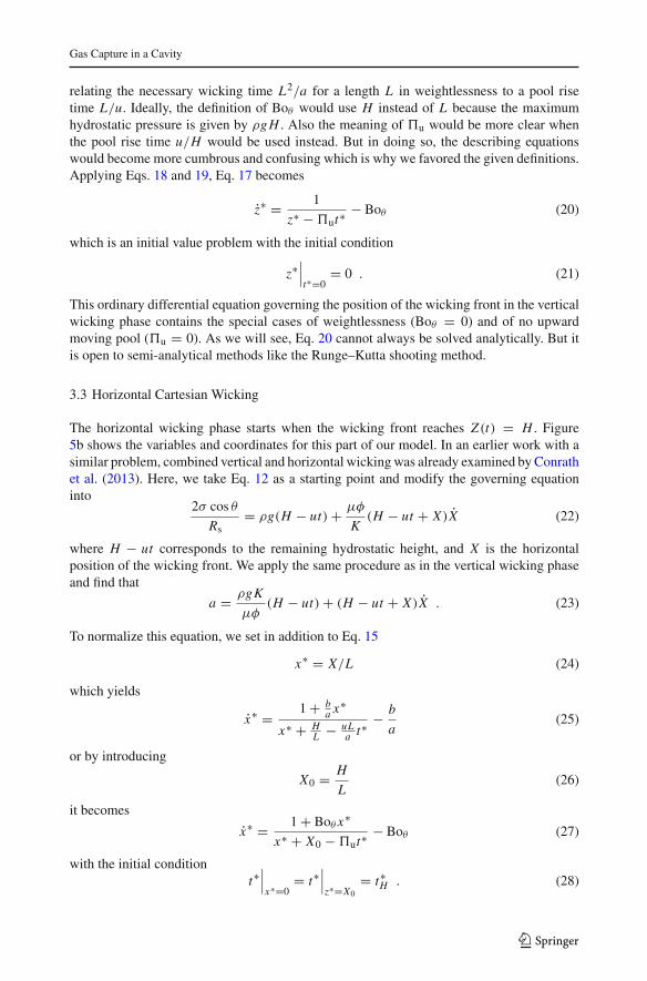
relating the necessary wicking time L2/a for a length L in weightlessness to a pool risetime L/u. Ideally, the definition of Boθ would use H instead of L because the maximumhydrostatic pressure is given by ρgH . Also the meaning of �u would be more clear whenthe pool rise time u/H would be used instead. But in doing so, the describing equationswould become more cumbrous and confusing which is why we favored the given definitions.Applying Eqs. 18 and 19, Eq. 17 becomes
z∗ = 1
z∗ − �ut∗− Boθ (20)
which is an initial value problem with the initial condition
z∗∣∣∣t∗=0
= 0 . (21)
This ordinary differential equation governing the position of the wicking front in the verticalwicking phase contains the special cases of weightlessness (Boθ = 0) and of no upwardmoving pool (�u = 0). As we will see, Eq. 20 cannot always be solved analytically. But itis open to semi-analytical methods like the Runge–Kutta shooting method.
3.3 Horizontal Cartesian Wicking
The horizontal wicking phase starts when the wicking front reaches Z(t) = H . Figure5b shows the variables and coordinates for this part of our model. In an earlier work with asimilar problem, combined vertical and horizontal wicking was already examined by Conrathet al. (2013). Here, we take Eq. 12 as a starting point and modify the governing equationinto
2σ cos θ
Rs= ρg(H − ut) + μφ
K(H − ut + X)X (22)
where H − ut corresponds to the remaining hydrostatic height, and X is the horizontalposition of the wicking front. We apply the same procedure as in the vertical wicking phaseand find that
a = ρgK
μφ(H − ut) + (H − ut + X)X . (23)
To normalize this equation, we set in addition to Eq. 15
x∗ = X/L (24)
which yields
x∗ = 1 + ba x∗
x∗ + HL − uL
a t∗− b
a(25)
or by introducing
X0 = H
L(26)
it becomes
x∗ = 1 + Boθ x∗
x∗ + X0 − �ut∗− Boθ (27)
with the initial conditiont∗
∣∣∣x∗=0
= t∗∣∣∣z∗=X0
= t∗H . (28)
123
M. Conrath, Y. Smiyukha
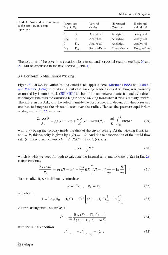
Table 1 Availability of solutionsto the capillary transportequations
Parameters Vertical Horizontal HorizontalBoθ & �u (both) Cartesian cylindrical
0 0 Analytical Analytical Analytical
Boθ 0 Analytical Analytical Analytical
0 �u Analytical Analytical Analytical
Boθ �u Runge–Kutta Runge–Kutta Runge–Kutta
The solutions of the governing equations for vertical and horizontal section, see Eqs. 20 and27, will be discussed in the next section (Table 1).
3.4 Horizontal Radial Inward Wicking
Figure 5c shows the variables and coordinates applied here. Marmur (1988) and Daninoand Marmur (1994) studied radial outward wicking. Radial inward wicking was formerlyexamined by Conrath et al. (2010,2013). The difference between cartesian and cylindricalwicking originates in the shrinking length of the wicking front when it travels radially inward.Therefore, in the disk, also the velocity inside the porous medium depends on the radius andone has to integrate the viscous losses over the radius. Hence, the pressure equilibriumanalogous to Eq. 22 becomes
2σ cos θ
Rs= ρg(H − ut) + μφ
K(H − ut)v(R0) + μφ
K
∫ R
R0
v(r)dr (29)
with v(r) being the velocity inside the disk of the cavity ceiling. At the wicking front, i.e.,at r = R, this velocity is given by v(R) = −R. And due to conservation of the liquid flowrate Qr in the disk, because Qr = 2π Rd R = 2πrdv(r), it is
v(r) = 1
rR R (30)
which is what we need for both to calculate the integral term and to know v(R0) in Eq. 29.It then becomes
2σ cos θ
Rs= ρg(H − ut) − μφ
KR R
[(H − ut)
1
R0− ln
R
R0
]. (31)
To normalize it, we additionally introduce
R = r∗L , R0 = �L (32)
and obtain
1 = Boθ (X0 − �ut∗) − r∗r∗[(X0 − �ut∗) 1
�− ln
r∗
�
]. (33)
After rearrangement we arrive at
r∗ = 1
r∗Boθ (X0 − �ut∗) − 11�(X0 − �ut∗) − ln r∗
�
(34)
with the initial conditiont∗
∣∣∣r∗=�
= t∗∣∣∣z∗=X0
= t∗H . (35)
123
Gas Capture in a Cavity
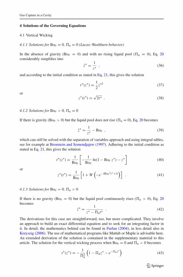
4 Solutions of the Governing Equations
4.1 Vertical Wicking
4.1.1 Solutions for Boθ = 0, �u = 0 (Lucas–Washburn behavior)
In the absence of gravity (Boθ = 0) and with no rising liquid pool (�u = 0), Eq. 20considerably simplifies into
z∗ = 1
z∗ , (36)
and according to the initial condition as stated in Eq. 21, this gives the solution
t∗(z∗) = 1
2z∗2 (37)
orz∗(t∗) = √
2t∗ . (38)
4.1.2 Solutions for Boθ > 0, �u = 0
If there is gravity (Boθ > 0) but the liquid pool does not rise (�u = 0), Eq. 20 becomes
z∗ = 1
z∗ − Boθ , (39)
which can still be solved with the separation of variables approach and using integral tables,see for example at Bronstein and Semendjajew (1997). Adhering to the initial condition asstated in Eq. 21, this gives the solution
t∗(z∗) = 1
Boθ
[− 1
Boθ
ln(1 − Boθ z∗) − z∗]
(40)
or
z∗(t∗) = 1
Boθ
[1 + W
(−e−(Boθ
2t∗+1))]
. (41)
4.1.3 Solutions for Boθ = 0, �u > 0
If there is no gravity (Boθ = 0) but the liquid pool continuously rises (�u > 0), Eq. 20becomes
z∗ = 1
z∗ − �ut∗. (42)
The derivations for this case are straightforward, too, but more complicated. They involvean approach to build an exact differential equation and to seek for an integrating factor init. In detail, the mathematics behind can be found in Furlan (2004), in less detail also inKreyszig (2006). The use of mathematical programs like Matlab or Maple is advisable here.An extended derivation of the solution is contained in the supplementary material to thisarticle. The solution for the vertical wicking process when Boθ = 0 and �u > 0 becomes
t∗(z∗) = − 1
�2u
(1 − �uz∗ − e−�uz∗)
(43)
123
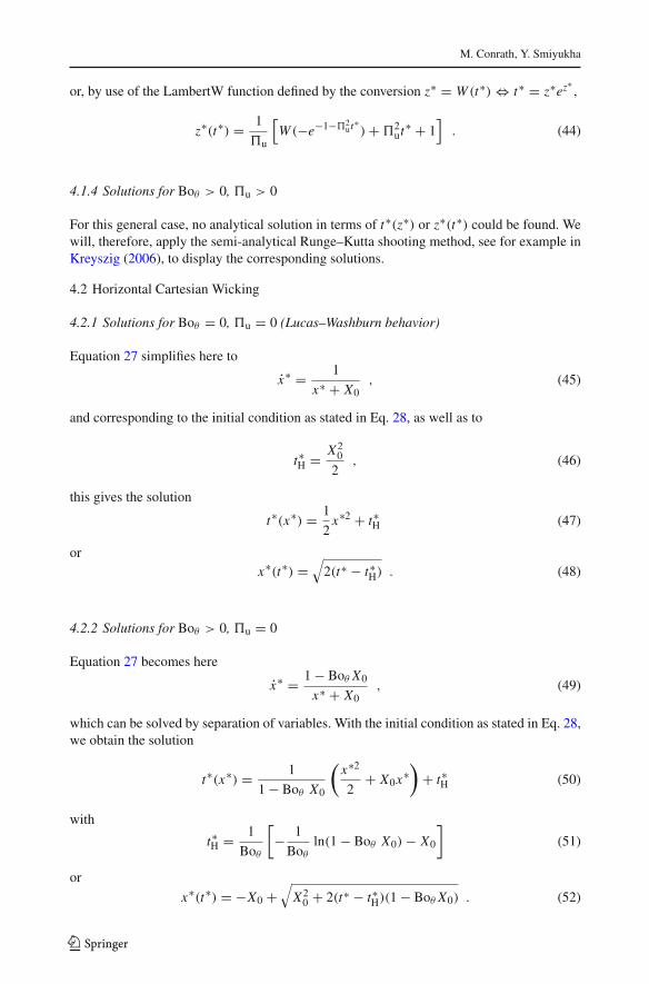
M. Conrath, Y. Smiyukha
or, by use of the LambertW function defined by the conversion z∗ = W (t∗) ⇔ t∗ = z∗ez∗,
z∗(t∗) = 1
�u
[W (−e−1−�2
ut∗) + �2ut∗ + 1
]. (44)
4.1.4 Solutions for Boθ > 0, �u > 0
For this general case, no analytical solution in terms of t∗(z∗) or z∗(t∗) could be found. Wewill, therefore, apply the semi-analytical Runge–Kutta shooting method, see for example inKreyszig (2006), to display the corresponding solutions.
4.2 Horizontal Cartesian Wicking
4.2.1 Solutions for Boθ = 0, �u = 0 (Lucas–Washburn behavior)
Equation 27 simplifies here to
x∗ = 1
x∗ + X0, (45)
and corresponding to the initial condition as stated in Eq. 28, as well as to
t∗H = X20
2, (46)
this gives the solution
t∗(x∗) = 1
2x∗2 + t∗H (47)
orx∗(t∗) =
√2(t∗ − t∗H) . (48)
4.2.2 Solutions for Boθ > 0, �u = 0
Equation 27 becomes here
x∗ = 1 − Boθ X0
x∗ + X0, (49)
which can be solved by separation of variables. With the initial condition as stated in Eq. 28,we obtain the solution
t∗(x∗) = 1
1 − Boθ X0
(x∗2
2+ X0x∗
)+ t∗H (50)
with
t∗H = 1
Boθ
[− 1
Boθ
ln(1 − Boθ X0) − X0
](51)
or
x∗(t∗) = −X0 +√
X20 + 2(t∗ − t∗H)(1 − Boθ X0) . (52)
123
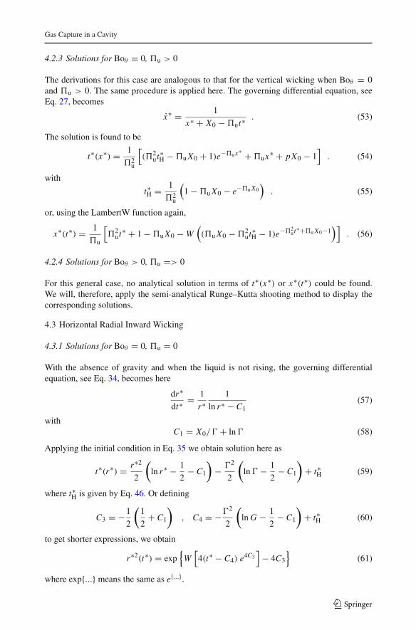
Gas Capture in a Cavity
4.2.3 Solutions for Boθ = 0, �u > 0
The derivations for this case are analogous to that for the vertical wicking when Boθ = 0and �u > 0. The same procedure is applied here. The governing differential equation, seeEq. 27, becomes
x∗ = 1
x∗ + X0 − �ut∗. (53)
The solution is found to be
t∗(x∗) = 1
�2u
[(�2
ut∗H − �u X0 + 1)e−�ux∗ + �ux∗ + pX0 − 1]
. (54)
with
t∗H = 1
�2u
(1 − �u X0 − e−�u X0
). (55)
or, using the LambertW function again,
x∗(t∗) = 1
�u
[�2
ut∗ + 1 − �u X0 − W((�u X0 − �2
ut∗H − 1)e−�2ut∗+�u X0−1
)]. (56)
4.2.4 Solutions for Boθ > 0, �u => 0
For this general case, no analytical solution in terms of t∗(x∗) or x∗(t∗) could be found.We will, therefore, apply the semi-analytical Runge–Kutta shooting method to display thecorresponding solutions.
4.3 Horizontal Radial Inward Wicking
4.3.1 Solutions for Boθ = 0, �u = 0
With the absence of gravity and when the liquid is not rising, the governing differentialequation, see Eq. 34, becomes here
dr∗
dt∗= 1
r∗1
ln r∗ − C1(57)
withC1 = X0/� + ln � (58)
Applying the initial condition in Eq. 35 we obtain solution here as
t∗(r∗) = r∗2
2
(ln r∗ − 1
2− C1
)− �2
2
(ln � − 1
2− C1
)+ t∗H (59)
where t∗H is given by Eq. 46. Or defining
C3 = −1
2
(1
2+ C1
), C4 = −�2
2
(ln G − 1
2− C1
)+ t∗H (60)
to get shorter expressions, we obtain
r∗2(t∗) = exp{
W[4(t∗ − C4) e4C3
]− 4C3
}(61)
where exp{...} means the same as e{...}.
123
M. Conrath, Y. Smiyukha
4.3.2 Solutions for Boθ > 0, �u = 0
This case is basically the same as the one before because the governing differential equationis just multiplied by a constant factor. Here, Eq. 34 becomes
dr∗
dt∗= 1
r∗1 − Boθ X0
ln r∗ − C1. (62)
With the initial condition Eq. 35 we obtain
t∗(r∗) = 1
1 − Boθ X0
[r∗2
2
(ln r∗ − 1
2− C1
)− �2
2
(ln � − 1
2− C1
)]+ t∗H (63)
where t∗H is given by Eq. 51. Or
r∗2(t∗) = exp{
W[4
(t∗ − Boθ X0t∗ − C4
)e4C3
]− 4C3
}. (64)
4.3.3 Solutions for Boθ = 0, �u > 0
With the absence of gravity but the liquid rising, the governing differential Eq. 34 becomes
dr∗
dt∗= 1
r∗1
ln r∗ − C1 + C2t∗(65)
with
C2 = �u/� . (66)
With the initial condition Eq. 35 we obtain
t∗(r∗) = t∗H e− C22 (�2−r∗2) + C1
C2
(1 − e− C2
2 (�2−r∗2))
− 1
2C2
(ln r∗2 − ln �2 e− C2
2 (�2−r∗2))
−e+ C22 r∗2
2C2
[E1
(C2
2r∗2
)− E1
(C2
2�2
)]. (67)
where t∗H is given by Eq. 55 and E1 is the exponential integral
E1(z) =∫ ∞
z
e−t
tdt . (68)
An explicit expression r∗(t∗) could not be found here.
4.3.4 Solutions for Boθ > 0, �u > 0
For this general case, no analytical solution in terms of t∗(r∗) or r∗(t∗) could be found. Soagain, we will, therefore, apply here the semi-analytical Runge–Kutta shooting method todisplay the corresponding solutions.
5 Results
5.1 Wicking Process
To illustrate the wicking process, it is helpful to employ a meaningful critical Bond numberBoc and a critical pool rise parameter�c. Boc refers to the situation where the capillary suction
123
Gas Capture in a Cavity
X = 0.50
horizontal wickingvertical wicking
Bo ,= 0 = 0= 0
Bo = 0Bo Bo ,= 0.5 = 0.5c
Bo Bo ,= =Bo Bo ,= 2 =
c
c c
c c
c
Bo
Bo
=0.
5
Bo
Bo
=c
X0
u
u
u
u
u
= 0.5c
u
=c
u
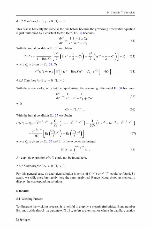
Fig. 6 Wicking in Cartesian arrangement: courses for the (i) Lucas–Washburn behavior (black dotted line),(ii) capillary rise without pool elevation at two different Bond numbers (blue dash-dotted lines), (iii) pool riseat weightlessness at two different velocities (green dashed lines) and (iv) combined pool rise and gravity atthree different parameter combinations (red lines with data points)
pressure equals the hydrostatic pressure over the cavity height H . If our Bond number, seeEq. 18, was defined using H instead of L , a Bond number of unity would at once depictthis critical situation. As we used L which is greater than H , Boc must be correspondinglygreater, too, and becomes
Boc = Boθ
X0. (69)
Similarly, a critical parameter �c for the velocity of the pool rise is defined that refers tocavity closure in the moment the pool reaches the upper edge of the cavity. Considering thedefinition of �u, see Eq. 19, it is
�c = �u
X0(70)
which relates the wicking time L2/a to the pool rise time H/u. Figures 6 and 7 show anumber of characteristic courses of the wicking process for the Cartesian and the cylindricalarrangement, respectively. In both figures, an aspect ratio X0 = 0.5 was chosen. Each of thetwo figures contains and displays the eight partial solutions presented before. For vertical aswell as horizontal section, there are the courses for the (i) Lucas–Washburn behavior (blackdotted line), (ii) capillary rise without pool elevation at two different Bond numbers (bluedash-dotted lines), (iii) pool rise at weightlessness at two different velocities (green dashedlines), and (iv) combined pool rise and gravity at three different parameter combinations (redlines with data points). The analytical solutions from (i) to (iii) have been used as benchmarkto evaluate the accuracy of the semi-analytical Runge–Kutta method. For the latter, a stepsize of 0.01 was used which makes a total of 100 steps over z∗ + x∗ or z∗ + � − r∗,respectively, and a corresponding error is equal to 10−8 because it is a shooting method of 4thorder.
123
M. Conrath, Y. Smiyukha
horizontal wickingvertical wicking
X = 0.50
Bo ,= 0 = 0= 0
Bo = 0Bo Bo ,= 0.5 = 0.5c
Bo Bo ,= =Bo Bo ,= 2 =
c
c c
c c
u
u
u
u
u
X0
r= c
u
= 0.5 c
u
c
Bo
Bo
=0.
5
Bo
Bo
=c
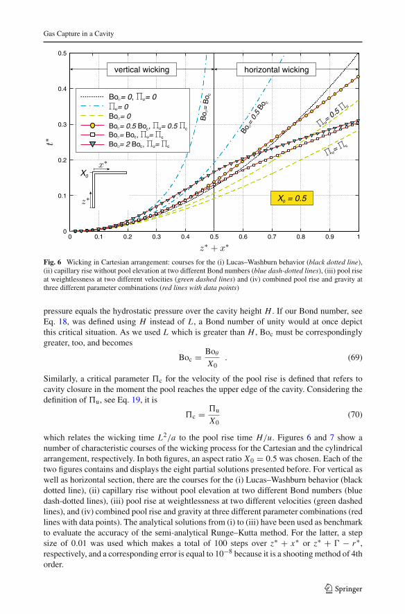
Fig. 7 Wicking in cylindrical arrangement: courses for the (i) Lucas–Washburn behavior (black dotted line),(ii) capillary rise without pool elevation at two different Bond numbers (blue dash-dotted lines), (iii) pool riseat weightlessness at two different velocities (green dashed lines), and (iv) combined pool rise and gravity atthree different parameter combinations (red lines with data points)
Qualitatively, it shows that already the Lucas–Washburn behavior is different in the twoarrangements. While in Cartesian arrangement, the curve is parabolic and ends exactly att∗ = 0.5, the curve for cylindrical arrangement has an inflection point and it ends at muchsmaller time at about t∗ = 0.32. The capillary rise in both arrangements is limited by thecritical Bond number where the liquid cannot reach the horizontal section. Naturally, theadditional hydrostatic pressure that has to be overcome slows down the wicking process.The opposite can be seen when the liquid pool rises in weightlessness. This can be attributedto the steady decrease of the viscous flow path through the porous medium. An interestingconsequence arises when there is capillary rise, while the liquid pool rises, too. Because thenthe retarding effect of gravity is counteracted by the shrinking viscous length. Moreover, alsothe hydrostatic height is then steadily decreased which means that the critical Bond numberis then time dependent. Hence, the “initial” critical Bond number is eventually diminishedso far that the liquid can also enter the horizontal section.
5.2 Closure Time
Once we are able to describe the wicking process, we can also predict the closure time thatis when the horizontal wicking ends, and thus, the cavity is closed. In Figs. 6 and 7, t∗c is thetime at the rightmost position. The closure time is
t∗c ={
t∗(z∗ + x∗) = 1 Cartesiant∗(z∗ + � − r∗) = 1 cylindical
. (71)
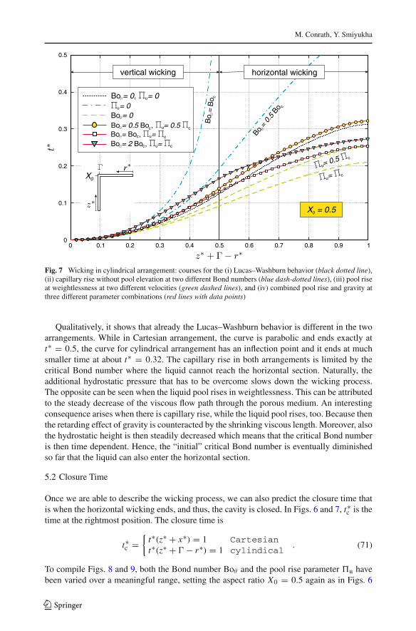
To compile Figs. 8 and 9, both the Bond number Boθ and the pool rise parameter �u havebeen varied over a meaningful range, setting the aspect ratio X0 = 0.5 again as in Figs. 6
123
Gas Capture in a Cavity
0 0.2 0.4 0.6 0.8 1 1.2 1.4 1.6 1.8 20
0.1
0.2
0.3
0.4
0.5
0.6
0.7
0.8
0.9
1Π
u
0.4
0.5
0.6
0.7
0.8
0.9
1
1.2
1.5
23
5
X = 0.50
closure time tc
Cartesian
Fig. 8 Closure times in the Cartesian arrangement. Clearly, the closure time increases with growing Bondnumber Boθ but decreases with growing pool rise parameter �u
0 0.2 0.4 0.6 0.8 1 1.2 1.4 1.6 1.8 20
0.1
0.2
0.3
0.4
0.5
0.6
0.7
0.8
0.9
1
Πu
X = 0.50
closure time tc
0.3
0.4
0.5
0.6
0.7
0.8
0.9
1
1.2
1.52
3 5
cylindrical
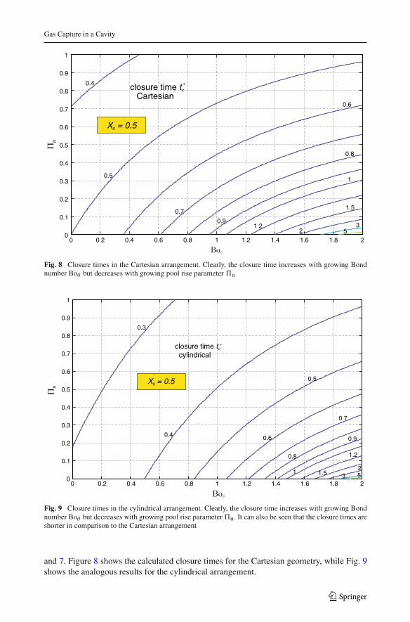
Fig. 9 Closure times in the cylindrical arrangement. Clearly, the closure time increases with growing Bondnumber Boθ but decreases with growing pool rise parameter �u. It can also be seen that the closure times areshorter in comparison to the Cartesian arrangement
and 7. Figure 8 shows the calculated closure times for the Cartesian geometry, while Fig. 9shows the analogous results for the cylindrical arrangement.
123
M. Conrath, Y. Smiyukha
1∏
∏0
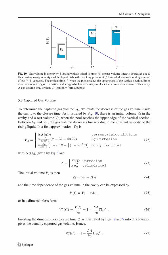
Fig. 10 Gas volume in the cavity. Starting with an initial volume V0, the gas volume linearly decreases due tothe constant rising velocity u of the liquid. When the wicking process at t∗c has ended, a corresponding amountof gas Vc is captured. The critical time t∗� when the pool reaches the upper edge of the vertical section, limitsalso the amount of gas to a critical value V� which is necessary to block the whole cross section of the cavity.A gas volume smaller than V� can only form a bubble
5.3 Captured Gas Volume
To determine the captured gas volume VC, we relate the decrease of the gas volume insidethe cavity to the closure time. As illustrated by Fig. 10, there is an initial volume V0 in thecavity and a rest volume V� when the pool reaches the upper edge of the vertical section.Between V0 and V�, the gas volume decreases linearly due to the constant velocity of therising liquid. In a first approximation, V� is
V� =
⎧⎪⎨⎪⎩
�z(1g)A terrestrialconditionsA W
4 cos2 θ(π − 2θ − sin 2θ) 0g,Cartesian
A R0cos3 θ
[1 − sin θ − 1
3 (1 − sin3 θ)]0g,cylindrical
(72)
with �z(1g) given by Eq. 3 and
A ={
2W D Cartesianπ R2
0 cylindrical(73)
The initial volume V0 is thenV0 = V� + H A (74)
and the time dependence of the gas volume in the cavity can be expressed by
V (t) = V0 − u At , (75)
or in a dimensionless form
V ∗(t∗) = V (t)
V0= 1 − L A
V0�ut∗ . (76)
Inserting the dimensionless closure time t∗c as illustrated by Figs. 8 and 9 into this equationgives the actually captured gas volume. Hence,
V ∗c (t∗) = 1 − L A
V0�ut∗c . (77)
123
Gas Capture in a Cavity
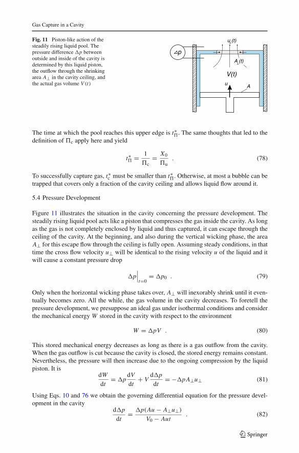
Fig. 11 Piston-like action of thesteadily rising liquid pool. Thepressure difference �p betweenoutside and inside of the cavity isdetermined by this liquid piston,the outflow through the shrinkingarea A⊥ in the cavity ceiling, andthe actual gas volume V (t) u A
u (t)
V(t)
pA (t)
The time at which the pool reaches this upper edge is t∗�. The same thoughts that led to thedefinition of �c apply here and yield
t∗� = 1
�c= X0
�u. (78)
To successfully capture gas, t∗c must be smaller than t∗�. Otherwise, at most a bubble can betrapped that covers only a fraction of the cavity ceiling and allows liquid flow around it.
5.4 Pressure Development
Figure 11 illustrates the situation in the cavity concerning the pressure development. Thesteadily rising liquid pool acts like a piston that compresses the gas inside the cavity. As longas the gas is not completely enclosed by liquid and thus captured, it can escape through theceiling of the cavity. At the beginning, and also during the vertical wicking phase, the areaA⊥ for this escape flow through the ceiling is fully open. Assuming steady conditions, in thattime the cross flow velocity u⊥ will be identical to the rising velocity u of the liquid and itwill cause a constant pressure drop
�p∣∣∣t=0
= �p0 . (79)
Only when the horizontal wicking phase takes over, A⊥ will inexorably shrink until it even-tually becomes zero. All the while, the gas volume in the cavity decreases. To foretell thepressure development, we presuppose an ideal gas under isothermal conditions and considerthe mechanical energy W stored in the cavity with respect to the environment
W = �pV . (80)
This stored mechanical energy decreases as long as there is a gas outflow from the cavity.When the gas outflow is cut because the cavity is closed, the stored energy remains constant.Nevertheless, the pressure will then increase due to the ongoing compression by the liquidpiston. It is
dW
dt= �p
dV
dt+ V
d�p
dt= −�p A⊥u⊥ (81)
Using Eqs. 10 and 76 we obtain the governing differential equation for the pressure devel-opment in the cavity
d�p
dt= �p(Au − A⊥u⊥)
V0 − Aut. (82)
123
M. Conrath, Y. Smiyukha
To find a normalized expression we introduce
�p∗ = �p
�p0(83)
and divide both numerator and denominator at the right-hand side of Eq. 82 by Au to obtain
d�p∗
dt∗= �p∗
(1 − A⊥
A
u⊥u
) / (V0
AL�u− t∗
). (84)
The two ratios A⊥/A and u⊥/u are
A⊥A
(Boθ ,�u) ={
1−X0−x∗1−X0
Cartesian
r∗2
�2 cylindrical(85)
and from Eq. 10
u⊥u
=
⎧⎪⎪⎪⎨⎪⎪⎪⎩
�p∗ when β = 0√1
�p0+�p∗
(2βKμ
)2− 1√�p0√
1�p0
+(
2βKμ
)2− 1√�p0
when β = 0, (86)
while V0 is given by Eq. 74. To illustrate the pressure development in the cavity for someexemplary cases, we assume that β = 0 and choose the same aspect ratio X0 as for theillustration of the wicking process. We distinguish four cases when implementing Eq. 84: (i)Cartesian in gravity (Boθ > 0), (ii) cylindrical in gravity, (iii) Cartesian in weightlessness,and (iv) cylindrical in weightlessness. To avoid the capillary length as additional parameterwe assume that Lσ << H for our examples. We choose the contact angle to be zero. Hence,according to Eq. 84, the pressure development in those cases will obey
d�p∗
dt∗=
⎧⎪⎪⎪⎪⎪⎪⎨⎪⎪⎪⎪⎪⎪⎩
�p∗(
1 − 1−X0−x∗1−X0
�p∗)
/ (X0/�u − t∗) 1g,Cartesian
�p∗(
1 − r∗2
�2 �p∗)
/ (X0/�u − t∗) 1g,cylindrical
�p∗(
1 − 1−X0−x∗1−X0
�p∗)
/[(
X0 + π4 (1 − X0)
)/�u − t∗
]0g,Cartesian
�p∗(
1 − r∗2
�2 �p∗)
/[(
X0 + 23 �
)/�u − t∗
]0g,cylindrical
(87)and can be evaluated by means of the Runge–Kutta method. Figures 12 and 13 show theoutcome of these evaluations for Cartesian and cylindrical arrangement, respectively.
It shows that the time dependence of the pressure is very similar in both geometries, butin the cylindrical arrangement the wicking process and, therefore, the pressure buildup, too,is slightly faster. It can be seen that the pressure inside the cavity remains constant whenthe liquid pool does not rise, i.e., when �u = 0. When it does rise, on the other hand, theliquid piston is activated and it compresses the gas in the cavity as the exit for the escapeflow closes. In the gravity cases where we neglected any rest volume V�, this would lead toinfinite pressure as the cavity is closed and the liquid piston hits the cavity ceiling at t = t�.This kind of behavior is shown by three cases in each of the two figures. When the liquidpool rises but gravity is absent, i.e., Boθ = 0, there remains a buffer volume V� as the liquidreaches the cavity ceiling. This buffer volume delays the singular pressure increase but cannotprevent it, since the imposed upward motion of the liquid piston will eventually compress itto zero volume, too.
123

Gas Capture in a Cavity
0 0.1 0.2 0.3 0.4 0.5 0.6 0.7 0.80.5
1
1.5
2
2.5
3
3.5Δ
= 0Bo = 0Bo Bo ,= 0.5
= 0.5c
Bo Bo ,=
=Bo Bo ,= 2
=
c
c
c
c
c
u
u
u
u
c
c
c
c
c
=c
u
= 0.5c
u X = 0.50
cu( )=0.5 cu( )=
Fig. 12 Pressure development in the Cartesian arrangement. Without the liquid pool rising, i.e., at �u = 0,the pressure remains unaltered. Due to the assumption that Lσ << H , the curves where Boθ > 0 tend toinfinity as the pool hits the cavity ceiling. At Boθ = 0, on the other hand, the remaining gas volume V� at t�acts like a buffer and delays this singular pressure increase
0 0.1 0.2 0.3 0.4 0.5 0.6 0.7 0.80.5
1
1.5
2
2.5
3
3.5
= 0Bo = 0Bo Bo ,= 0.5
= 0.5c
Bo Bo ,=
=Bo Bo ,= 2
=
c
c
c
c
c
u
u
u
u
=c
u =0.
5c
u
Δ
cu( )=0.5 cu( )=
X = 0.50c
c
c
c
c
Fig. 13 Pressure development in the cylindrical arrangement. Without the liquid pool rising, i.e., �u = 0,the pressure remains unaltered. Due to the assumption that Lσ << H , the curves where Boθ > 0 tend toinfinity as the pool hits the cavity ceiling. At Boθ = 0, on the other hand, the remaining gas volume V� at t�acts like a buffer and delays this singular pressure increase
Naturally, in reality there would be no infinite pressure. Instead, the captured gas wouldbreak through the pores of the cavity ceiling as soon as the pressure difference �p across it
123
M. Conrath, Y. Smiyukha
surpasses the bubble point threshold. As shown in Fig. 3e, the gas would then exit the cavity,and the capture could not be uphold. However, the gas breakthrough shall not be consideredhere because this was already done by Conrath and Dreyer (2012). Also the leakage, aspictured in Fig. 3e, was already described, see Conrath et al. (2013), hence we do not needto repeat it here.
6 Summary and Discussion
The main focus of this study was laid on the description of the wicking process that enablesthe capture of gas in a cavity with porous walls. A novelty is that the liquid pool rises duringthe wicking process. The wicking process itself is an initial value problem and combines avertical wicking phase preceding a horizontal wicking phase. The end of the vertical wickingphase thus poses an initial condition for the horizontal wicking phase. This problem wasconsidered for mirror-symmetric Cartesian as well as axially symmetric cylindrical arrange-ment. Moreover, both gravity and weightlessness were accounted for. Imposing the necessaryassumptions of (i) simplified saturation conditions, (ii) neglect of contact angle dynamics,and (iii) thin walls, we have derived normalized equations in which only three basic parame-ters determine the problem. These are a Bond number Boθ relating hydrostatic to capillarysuction pressure, a liquid rise parameter �u relating characteristic wicking time to pool risetime, and the aspect ratio X0 of the cavity. As far as possible, analytical solutions for thiswicking process were derived. Especially the analytical solutions for the pool rise in weight-lessness, i.e., when Boθ = 0 and �u > 0, are of novel character. If analytical solutions werenot possible, the presented ordinary differential equations that govern the wicking processwere evaluated using the Runge–Kutta shooting method. For a fixed aspect ratio X0 = 0.5,a number of representative time dependences of the wicking process is presented for botharrangements. Based on the knowledge of the wicking process, we were able to determinethe closure time that is necessary to complete the wicking process and after which gas istrapped inside the cavity. In addition, we describe the time dependence of gas volume in thecavity and tackle the corresponding pressure development inside it.
Overall, our study provides a mean to optimize possible applications, for example, aliquid blocker, and to understand the behavior of such systems—may they occur in technicalapplications or in nature. As we have shown, the pressure evolution in the cavity is coupledto the wicking process and thus to the rise velocity of the liquid. As a consequence, fromthe measurement of the pressure development in such a system, one may also conclude theliquid rise velocity.
7 Supplementary Material
To alleviate understanding and thus application of our model, we provide an extended versionof our analytical solutions as online supplementary material.
Acknowledgments The funding of the research project by the German Federal Ministry of Economicsand Technology (BMWi) through the German Aerospace Center (DLR) under grant number 50 RL 0921 isgratefully acknowledged.
References
Aubertin, M., Cifuentes, E., Apithy, S., Bussiere, B., Molson, J., Chapuis, R.: Analyses of water diversionalong inclined covers with capillary barrier effects. Can. Geotech. J. 46, 1146–1164 (2009)
123
Gas Capture in a Cavity
Barth, H.: Sustainable and effective irrigation through a new subsoil irrigation system. Agric. Water Manag.40, 283–290 (1999)
Ben-Gal, A., Lazorovitch, N., Shani, U.: Subsurface drip irrigation in gravel-filled cavities. Vadose Zone J.3(4), 1407–1413 (2004)
Bennion, D., Bietz, R., Thomas, F., Cimolai, M.: Reductions in the productivity of oil and low permeabilitygas reservoirs due to aqueous phase trapping. J. Can. Pet. Technol. 33(9), 19–30 (1994)
Bennion, D., Thomas, F., Bietz, R.: Water and hydrocarbon phase trapping in porous media-diagnosis, pre-vention and treatment. J. Can. Pet. Technol. 35(10), 1–8 (1996)
Blom, C., Voeseneck, L.: Flooding: the survival strategies of plants. Tree 11(7), 290–295 (1996)Bronstein, I., Semendjajew, K.: Handbook of Mathematics, 3rd edn. Springer, Berlin (1997)Conrath, M., Dreyer, M.E.: Gas breakthrough at a porous screen. Int. J. Multiph. Flow 42, 29–41 (June 2012)Conrath, M., Fries, N., Zhang, M., Dreyer, M.E.: Radial capillary transport from an infinite reservoir. Transp.
Porous Media 84(1), 109–132 (2010)Conrath, M., Smiyukha, Y., Fuhrmann, E., Dreyer, M.: Double porous screen element for gas-liquid phase
separation. Int. J. Multiph. Flow 50, 1–15 (April 2013)Danino, D., Marmur, A.: Radial capillary penetration into paper: limited and unlimited liquid reservoirs. J.
Colloid Interface Sci. 166(1), 245–250 (1994)de Gennes, P.: Wetting: statics and dynamics. Rev. Mod. Phys. 57(3), 827–863 (1985)Dodge, F.: The New Dynamic Behavior of Liquids in Moving Containers. Southwest Research Institute, San
Antonio (2000)Fries, N., Dreyer, M.: An analytic solution of capillary rise restrained by gravity. J. Colloid Interface Sci. 320,
259–263 (2008)Furlan, P.: Das gelbe Rechenbuch fr Ingenieure, Naturwissenschaftler und Mathematiker: Rechenverfahren
der hheren Mathematik in Einzelschritten erklrt, Mit vielen ausfhrlich gerechneten Beispielen. Band 3:Gewhnliche Differentialgleichungen, Funktionentheorie, Integraltransformationen, partielle Differential-gleichungen. Furlan, Dortmund (2004)
Hickman, G.: Adaptiveness of tunnel system features in subterranean mammal burrows. Prog. Clin. Biol. Res.335, 185–210 (1990)
Jurn, J.M., Kudlac, M.T.: Nasa glenn research center creek road complex—cryogenic testing facilities. Cryo-genics 46, 98–104 (2006)
Jurns, J.M., McQuillen, J.B.: Liquid acquisition device testing with sub-cooled liquid oxygen. In: AIAA (Ed.),44th AIAA/ASME/SAE/ASEE Joint Propulsion Conference and Exhibit. No. AIAA 2008–4943. Hartford,CT July 2008
Justin, S., Armstrong, W.: The anatomical characteristics of root and plant response to soil flooding. NewPhytol. 106(3), 465–495 (1987)
Kreyszig, E.: Advanced Engineering Mathematics, 9th edn. Wiley, Hoboken (2006)Kudlac, M.T., Jurns, J.M.: Screen channel liquid acquisition devices for liquid oxygen. In: 42nd
AIAA/ASME/SAE/ASEE Joint Propulsion Conference and Exhibit. No. AIAA 2006–5054. AIAA, pp.1–9. Sacramento, CA, July 2006
Langbein, D.: Capillary Surfaces: Shape, Stability and Dynamics—in Particular Under Weightlessness.Springer, Heidelberg (2002)
Lazarovitch, N., Simunek, J., Shani, U.: System-dependent boundary condition for water flow from subsurfacesource. Soil Sci. Soc. Am. J. 69, 46–50 (2005)
Lucas, R.: Ueber das zeitgesetz des kapillaren anstiegs von fluessigkeiten. Kolloid Z. 23, 15–22 (1918)Lukas, D., Soukupova, V.: Recent studies of fibrous materials wetting dynamics. In: Index 99 Congress, pp.
1–11. Geneva, Switzerland 1999Maitland, D., Maitland, A.: Significance of burrow-opening diameter as a flood-prevention mechanism for
air-filled burrows of small intertidal arthropods. Mar. Biol. 119, 221–225 (1994)Marmur, A.: The radial capillary. J. Colloid Interface Sci. 124(1), 301–308 (1988)Suekane, T., Zhou, N., Hosokawa, T., Matsumoto, T.: Direct observation of trapped gas bubbles by capillarity
in sandy porous media. Transp. Porous Media 82, 111–122 (2010)Wang, Z., Feyen, J., van Genuchten, M., Nielsen, D.: Air entrapment effects on infiltration rate and flow
instability. Water Resour. Res. 34(2), 213–222 (1998)Washburn, E.: The dynamics of capillary flow. Phys. Rev. 17(3), 273–283 (1921)Wildenschild, D., Armstrong, R., Herring, A., Young, I., Carey, J.: Exploring capillary trapping efficiency as
a function of interfacial tension, viscosity, and flow rate. Energy Procedia 4, 4945–4952 (2011)Zhen, Z., Grigg, R.: A criterion for non-darcy flow in porous media. Transp. Porous Med. 65, 57–69 (2006)Zhou, N., Hosokawa, T., Suekane, T., Wang, Q.: Experimental trapping of capillary trapping on the pore scale
of various sandstone cores. Energy Procedia 4, 5017–5023 (2011)
123