Embed Size (px)
Citation preview
GAS BURNERS
GBC/GBS
DESCRIPTION n
n
n
n
n
n
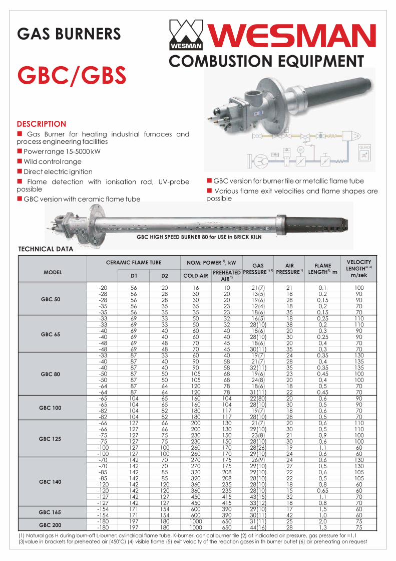
Gas Burner for heating industrial furnaces and process engineering facilities
Power range 15-5000 kW
Wild control range
Direct electric ignition
Flame detection with ionisation rod, UV-probe possible
GBC version with ceramic flame tube
n
n
GBC version for burner tile or metallic flame tube
Various flame exit velocities and flame shapes are possible
GBC HIGH SPEED BURNER 80 for USE in BRICK KILN
(1) Natural gas H during burn-off L-burner: cylindrical flame tube, K-burner: conical burner tile (2) at indicated air pressure, gas pressure for =1,1 0(3)value in brackets for preheated air (450 C) (4) visible flame (5) exit velocity of the reaction gases in th burner outlet (6) air preheating on request
TECHNICAL DATA
MODEL
-20-28-28-35-35-33-33-40-40-48-48-33-40-40-50-50-64-64-65-65-82-82-66-66-75-75
-100-100-70-70-85-85
-120-120-127-127-154-154-180-180
565656565669696969696987878787878787
104104104104127127127127127127142142142142142142142142171171197197
2028283535333340404848334040505064646565828266667575
10010070708585
120120127127154154180180
1630303535505060607070609090
105105120120160160180180200200230230260260270270320320360360450450600600
10001000
102020232332324040454540585868687878
104104117117130130150150170170175175208208235235415415390390650650
21(7)13(5)19(6)12(4)18(6)16(5)
28(10)18(6)
28(10)18(6)
30(11)19(7)21(7)
32(11)19(6)24(8)18(6)
31(11)22(80)28(10)19(7)
28(10)21(7)
29(10)23(8)
28(10)28(26)29(10)26(9)
29(10)29(10)28(10)28(10)28(10)43(15)33(12)29(10)30(11)31(11)44(16)
21182818351838203020352428352320182220301828203021301924242722221815321817422528
0,10,2
0,150,2
0,150,250,20,3
0,250,40,3
0,350,4
0,350,450,40,5
0,450,60,50,60,50,60,50,90,61,10,60,60,50,60,50,8
0,651,10,81,51,02,01,3
10090907070
11011090907070
130135135100100707090907070
1101101001006060
1301301051056060707060607575
COLD AIRPREHEATED
2)AIR
GAS 1) 2)PRESSURE
AIR 1)PRESSURE
FLAME2),LENGTH m
VELOCITY5), LENGTH
m/sek
6)
CERAMIC FLAME TUBE 1)NOM. POWER , kW
D1 D2
GBC 50
GBC 65
GBC 80
GBC 100
GBC 125
GBC 140
GBC 165
GBC 200
WESMANCOMBUSTION EQUIPMENT
FLAT FLAME
FLAT FLAME
FLAT FLAME
FLAT FLAME
FLAT FLAME
FLAT FLAME
FLAT FLAME
FLAT FLAME
TECHNICAL DATA
BURNER MODEL
LA A B C D D1 D2 E BL H K L M N O P X Y
DIMENSIONS (mm) APPROX WEIGHT
(kg)
NOMINAL POWER
DEPENDENT ON THE USED CERAMIC
TUBE, SEE TABLE“TECHNICAL DATA GBC”
GA
Rp ½”
Rp 3/4”
Rp 3/4”
Rp 1”
Rp 1 ½”
Rp 1 ½”
Rp 1 ½”
Rp 2”
SERIES
GBC
GBC
GBC
GBC
GBC
GBC
GBC
GBC
TYPE
50
65
80
100
125
140
165
200
Rp 1½”
Rp 1½”
Rp 2”
Rp 2”
Rp 65
DN 80
DN 100
DN 150
50
62
112
100
135
150
213
220
76
90
115
127
155
168
171
197
55
69
86
104
127
142
-
-
73
73
90
103
120
130
150
220
149
156
172
185
251
270
360
470
181
195
240
240
270
300
285
330
151
165
210
200
240
265
240
295
12
12
14
14
14
14
14
22
-
-
-
-
185
200
220
285
-
-
-
-
145
160
180
240
-
-
-
-
18
18
18
22
-
-
-
-
4
8
8
8
5
7
11
12
20
26
25
35
4
4
4
4
4
4
4
8
SEE T
EC
HN
.DA
TA G
BC
pa
ge
2
SEE B
UR
NER
LEN
GTH
S G
BC
pa
ge
6
38
48
55
60
73
80
52
75
235
177
190
16
355
380
360
500
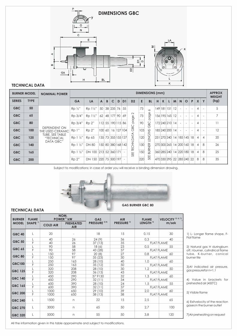
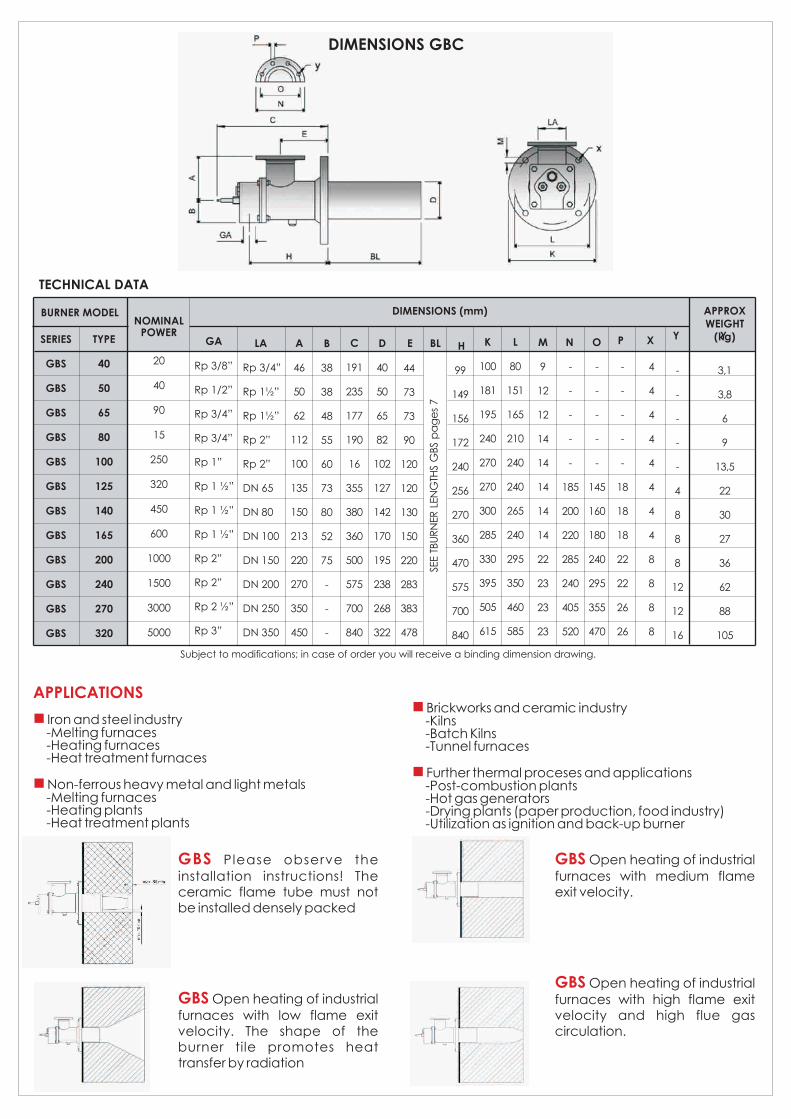
DIMENSIONS GBC
TECHNICAL DATA
BURNER MODEL
FLAME 1)SHAPE
NOM. 2)POWER kW
COLD AIRPREHEATED
AIR
GAS2) 4)PRESSURE
AIR2)PRESSURE
FLAME5)LENGTH
5)VELOCITY m/sek
6) 7) ,
GBC 40
GBC 50
GBC 65
GBC 80
GBC100
GBC 125
GBC 140
GBC 165
GBC 200
GBC 240
GBC 270
GBC 320
Subject to modifications; in case of order you will receive a binding dimension drawing.
All the information given in this table approximate and subject to modifications.
L
L
L
L
LFLFLFLFLFLFLFLF
20
1500
3000
5000
40409090
150150250250320320450450600600
10001000
-
n
n
n
262658589797163163208208290290390390650650
18
22
65
55
24 (9)37 (13)18 (6)
43 (28)20 (8)
35 (23)28 (10)35 (12)28 (10)36 (13)37 913032 (11)28 (10)32 (11)29 (10)38 (13)
15
15
50
50
36352337273040503043323424373938
0,15
2,5
2,7
3,8
0,3
0,5
0,8
1,0
1,2
1,3
1,5
2,0
30
65
100
120
40
55
60
60
50
60
55
60
1) L- Longer flame shape, F-Flat flame
2) Natural gas H duringburn off. l-burner, cylindrical flame tube, K-burner, conical burner tile
3)At indicated air pressure, gas pressurefor n=1,1
4) Value in brackets for 0preheated air (450 C)
5) Visible flame
6) Exitvelocity of the reaction gases in the burner outlet
7)Air preheating on request
GAS BURNER GBC 80
TECHNICAL DATA
BURNER MODEL DIMENSIONS (mm)NOMINAL
POWERGA
Rp 3/8”
Rp 1/2”
Rp 3/4”
Rp 3/4”
Rp 1”
Rp 1 ½”
Rp 1 ½”
Rp 1 ½”
Rp 2”
Rp 2”
Rp 2 ½”
Rp 3”
SERIES
GBS
GBS
GBS
GBS
GBS
GBS
GBS
GBS
GBS
GBS
GBS
GBS
TYPE
40
50
65
80
100
125
140
165
200
240
270
320
20
40
90
15
250
320
450
600
1000
1500
3000
5000
LA
Rp 3/4”
Rp 1½”
Rp 1½”
Rp 2”
Rp 2”
DN 65
DN 80
DN 100
DN 150
DN 200
DN 250
DN 350
A
46
50
62
112
100
135
150
213
220
270
350
450
D
40
50
65
82
102
127
142
170
195
238
268
322
BLE
44
73
73
90
120
120
130
150
220
283
383
478
H
99
149
156
172
240
256
270
360
470
575
700
840
K
100
181
195
240
270
270
300
285
330
395
505
615
L
80
151
165
210
240
240
265
240
295
350
460
585
M
9
12
12
14
14
14
14
14
22
23
23
23
N
-
-
-
-
-
185
200
220
285
240
405
520
O
-
-
-
-
-
145
160
180
240
295
355
470
P
-
-
-
-
-
18
18
18
22
22
26
26
X
4
4
4
4
4
4
4
4
8
8
8
8
Y
-
-
-
-
-
4
8
8
8
12
12
16
Y
3,1
3,8
6
9
13,5
22
30
27
36
62
88
105
SEE T
BU
RN
ER
LEN
GTH
S G
BS
pa
ge
s 7
B
38
38
48
55
60
73
80
52
75
-
-
-
C
191
235
177
190
16
355
380
360
500
575
700
840
DIMENSIONS GBC
Subject to modifications; in case of order you will receive a binding dimension drawing.
APPROX WEIGHT
(kg)
APPLICATIONS
n
n
Iron and steel industry -Melting furnaces -Heating furnaces -Heat treatment furnaces
Non-ferrous heavy metal and light metals -Melting furnaces -Heating plants -Heat treatment plants
GBS
GBS
Please observe the installation instructions! The ceramic flame tube must not be installed densely packed
Open heating of industrial furnaces with low flame exit velocity. The shape of the burner tile promotes heat transfer by radiation
GBS
GBS
Open heating of industrial furnaces with medium flame exit velocity.
Open heating of industrial furnaces with high flame exit velocity and high flue gas circulation.
n
n
Brickworks and ceramic industry -Kilns -Batch Kilns -Tunnel furnaces
Further thermal proceses and applications -Post-combustion plants -Hot gas generators -Drying plants (paper production, food industry) -Utilization as ignition and back-up burner
WESMAN THERMAL ENGINEERING PROCESSES PVT LTD WESMAN CENTER, 8 MAYFAIR ROAD, KOLKATA 700019, INDIATEL: +91 (33) 40020300 FAX: +91 (33) 22908050EMAIL: [email protected] WEBSITE: www.wesman.comInformation in this document is non-binding and subject to modification
REGIONAL SALES AND SERVICE OFFICES: MUMBAI (22) 28509521 DELHI NCR (129) 4005791 CHENNAI (44) 26561300 BANGALORE (80) 22225756 PUNE (20) 46703004 AHMEDABAD (79) 30027355 HYDERABAD (40) 66312686 NAGPUR (712) 2523424 RAIPUR JAMSHEDPUR LUDHIANA
n nn nn nn nnn n
*Air inlets of burners are in BSP thread
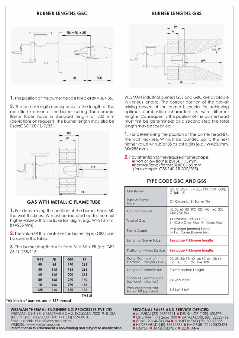
1.
2.
The position of the burner head is fixed at BK= BL + 35.
The burner length corresponds to the length of the metallic extension of the burner casing. The ceramic flame tubes have a standard length of 300 mm (deviations on request). The burner length may also be 0 (ex:GBC 100-1L- 0/35).
BURNER LENGTHS GBC BURNER LENGTHS GBS
WESMAN industrial burners GBS and GBC are available in various lengths. The correct position of the gas-air mixing device of the burner is crucial for achieving optimal combustion characteristics with different lengths. Consequently the position of the burner head must first be determined; as a second step the total length may be specified.
For determining the position of the burner head BK, the wall thickness W must be rounded up to the next higher value with 35 or 85 as last digits (e.g.: W=250 mm, BK=285 mm).
Pay attention to the required flame shape!short or low flame: BL=BK + 15 mmnormal (long) flame: BL=BK + 65 mm
(for example: GBS 140-1R-300/285)
1.
2. n n
GAS WITH METALLIC FLAME TUBE
TYPE CODE GBC AND GBS
1.
2.
3.
For determining the position of the burner head BK, the wall thickness W must be rounded up to the next higher value with 35 or 85 as last digits (e.g.: W=210 mm, BK=235 mm).
The value FR that matches the burner type (GBS) can be seen in the table.
The burner length results from BL = BK + FR (eg: GBS 65-1L-235/115)
TABLE
GBS
40
50
65
80
10
125
FR
65
115
115
165
165
215
GBS
140
165
200
240
270
320
FR
265
265
315
140
155
185
Gas Burner GB; C; 80; -1; L -100; /135; C50; (300); G; ipb 1,5
Type of Flame Tube
C= Ceramic; S= Burner Tile
Construction Size 40; 50; 65; 80; 100; 125; 140; 165; 200;240; 270; 300
Type of Gas 1= Natural Gas; 2= LPG; 3= Coke Oven Gas; 4= Mixed Gas
Flame Shape L= (Longer (normal) Flame F= Flat Flame (burner tile)
Length of Burner Tube See page 7,8:burner lengths
Position of Mixing Device See page 7,8:burner lengths
Outlet Diameter of Ceramic Tube (only GBC)
20; 28; 33; 35; 40; 48; 50; 64; 65; 66; 82; 100; 120; 127, 154; 180
Length of Ceramic Tub 300= Standard Length
Shape of Ceramic Tube (optional indication) R= Reduced
With Integrated Pilot Burner IPB (optional) 1.5 kW; 3 kW