Embed Size (px)
Citation preview

www.EmersonProcess.com
Instruction ManualHASX2NE-IM-EX12/2014
Gas AnalyzersX-STREAM X2 Series
Non-Incendive (Ex nA nC) Confi gurationfor Zone 2 and Division 2 Installations
Instruction Manual Addendum

ESSENTIAL INSTRUCTIONS READ THIS PAGE BEFORE PROCEEDING!
Emerson Process Management (Rosemount Analytical) designs, manufactures and tests its products to meet many national and international standards. Because these instruments are sophisticated technical products, you MUST properly install, use, and maintain them to ensure they continue to operate within their normal specifi cations. The following instructions MUST be adhered to and integrated into your safety program when installing, using and maintaining Emerson Process Management (Rosemount Analytical) products. Failure to follow the proper instructions may cause any one of the following situations to occur: Loss of life; personal injury; property damage; damage to this instrument; and warranty invalidation.
Read all instructions prior to installing, operating, and servicing the product.
If you do not understand any of the instructions, contact your Emerson Process Management (Rosemount Analytical) representative for clarifi cation.
Follow all warnings, cautions, and instructions marked on and supplied with the product.
Inform and educate your personnel in the proper installation, operation, and maintenance of the product.
Install your equipment as specifi ed in the Installation Instructions of the appropriate Instruction Manual and per applicable local and national codes. Connect all products to the proper electrical and pressure sources.
To ensure proper performance, use qualifi ed personnel to install, operate, update, program, and maintain the product.
When replacement parts are required, ensure that qualifi ed people use replacement parts specifi ed by Emerson Process Management (Rosemount Analytical). Unauthorized parts and procedures can affect the product’s performance, place the safe operation of your process at risk, and VOID YOUR WARRANTY. Look-alike substitutions may result in fi re, electrical hazards, or improper operation.
Ensure that all equipment doors are closed and protective covers are in place, except when maintenance is being performed by qualifi ed persons, to prevent electrical shock and personal injury.
The information within this document is subject to change without notice.6th Edition 12/2014
Original Instruction Manual for the purpose of the European Directive 94/9/EC.
Emerson Process Management GmbH & Co. OHGRosemount AnalyticalProcess Gas Analyzer Center of ExcellenceIndustriestrasse 163594 HasselrothGermanyT +49 6055 884 0F +49 6055 884 209

Emerson Process Management GmbH & Co. OHG TOC-1
X-STREAM Non-IncendiveInstruction ManualHASX2NE-IM-EX12/2014
TOC
Tabl
e of
con
tent
s
TABLE OF CONTENTS
Introduction S-1Defi nitions S-1Terms used in this instruction manual . . . . . . . . . . . . . . . . . . . . . . . . . . . . . . . . . . . . . . . . . . S-2Symbols used on and inside the unit . . . . . . . . . . . . . . . . . . . . . . . . . . . . . . . . . . . . . . . . . . . S-4Symbols used within this manual . . . . . . . . . . . . . . . . . . . . . . . . . . . . . . . . . . . . . . . . . . . . . . S-5
Safety Instructions S-6Intended Use Statement. . . . . . . . . . . . . . . . . . . . . . . . . . . . . . . . . . . . . . . . . . . . . . . . . . . . . S-6General Safety Notice / Residual risk. . . . . . . . . . . . . . . . . . . . . . . . . . . . . . . . . . . . . . . . . . . S-6Instructions for Safe Use . . . . . . . . . . . . . . . . . . . . . . . . . . . . . . . . . . . . . . . . . . . . . . . . . . . . S-6Authorized personnel . . . . . . . . . . . . . . . . . . . . . . . . . . . . . . . . . . . . . . . . . . . . . . . . . . . . . . . S-7Additional Literature . . . . . . . . . . . . . . . . . . . . . . . . . . . . . . . . . . . . . . . . . . . . . . . . . . . . . . . . S-7
Chapter 1 Technical Description 1-11.1 Analyzervariations covered by this manual . . . . . . . . . . . . . . . . . . . . . . . . . . . . . . . . . . .1-11.2 Application and Principle of Operation. . . . . . . . . . . . . . . . . . . . . . . . . . . . . . . . . . . . . . .1-11.3 Technical Data . . . . . . . . . . . . . . . . . . . . . . . . . . . . . . . . . . . . . . . . . . . . . . . . . . . . . . . . .1-31.3.1 Installation Site and Protection Method. . . . . . . . . . . . . . . . . . . . . . . . . . . . . . . . . . . . .1-31.3.2 Nameplate Label . . . . . . . . . . . . . . . . . . . . . . . . . . . . . . . . . . . . . . . . . . . . . . . . . . . . . .1-41.3.3 General Technical Data . . . . . . . . . . . . . . . . . . . . . . . . . . . . . . . . . . . . . . . . . . . . . . . . .1-51.4 Dimensions . . . . . . . . . . . . . . . . . . . . . . . . . . . . . . . . . . . . . . . . . . . . . . . . . . . . . . . . . . .1-61.5 Gas Specifi cations . . . . . . . . . . . . . . . . . . . . . . . . . . . . . . . . . . . . . . . . . . . . . . . . . . . . . .1-81.6 Measurements Specifi cations . . . . . . . . . . . . . . . . . . . . . . . . . . . . . . . . . . . . . . . . . . . . .1-91.7 Infallible Containments. . . . . . . . . . . . . . . . . . . . . . . . . . . . . . . . . . . . . . . . . . . . . . . . . .1-131.8 Instructions for safe use. . . . . . . . . . . . . . . . . . . . . . . . . . . . . . . . . . . . . . . . . . . . . . . . .1-13
Chapter 2 Installation 2-12.1 Scope of Supply. . . . . . . . . . . . . . . . . . . . . . . . . . . . . . . . . . . . . . . . . . . . . . . . . . . . . . . .2-12.2 General Safety Instructions . . . . . . . . . . . . . . . . . . . . . . . . . . . . . . . . . . . . . . . . . . . . . . .2-22.3 Abstract . . . . . . . . . . . . . . . . . . . . . . . . . . . . . . . . . . . . . . . . . . . . . . . . . . . . . . . . . . . . . .2-42.4 Mounting the Analyzer . . . . . . . . . . . . . . . . . . . . . . . . . . . . . . . . . . . . . . . . . . . . . . . . . . .2-42.5 Gas Conditioning . . . . . . . . . . . . . . . . . . . . . . . . . . . . . . . . . . . . . . . . . . . . . . . . . . . . . . .2-62.6 Gas Connections . . . . . . . . . . . . . . . . . . . . . . . . . . . . . . . . . . . . . . . . . . . . . . . . . . . . . . .2-82.7 Electrical Installation . . . . . . . . . . . . . . . . . . . . . . . . . . . . . . . . . . . . . . . . . . . . . . . . . . .2-102.7.1 External Equipotential Bonding Connector . . . . . . . . . . . . . . . . . . . . . . . . . . . . . . . . .2-19
Chapter 3 Startup 3-13.1 Safety Instructions and Final Check . . . . . . . . . . . . . . . . . . . . . . . . . . . . . . . . . . . . . . . .3-13.2 Performing a Leak Test . . . . . . . . . . . . . . . . . . . . . . . . . . . . . . . . . . . . . . . . . . . . . . . . . .3-2
Emerson Process Management GmbH & Co. OHGTOC-2
X-STREAM Non-IncendiveInstruction Manual
HASX2NE-IM-EX12/2014
3.3 Switching On . . . . . . . . . . . . . . . . . . . . . . . . . . . . . . . . . . . . . . . . . . . . . . . . . . . . . . . . . .3-33.4 Symbols and Typographical Conventions . . . . . . . . . . . . . . . . . . . . . . . . . . . . . . . . . . . .3-43.5 The user interface . . . . . . . . . . . . . . . . . . . . . . . . . . . . . . . . . . . . . . . . . . . . . . . . . . . . . .3-53.5.1 Display. . . . . . . . . . . . . . . . . . . . . . . . . . . . . . . . . . . . . . . . . . . . . . . . . . . . . . . . . . . . . .3-63.5.2 Status LED . . . . . . . . . . . . . . . . . . . . . . . . . . . . . . . . . . . . . . . . . . . . . . . . . . . . . . . . . .3-63.5.3 Keys 3-73.6 Software. . . . . . . . . . . . . . . . . . . . . . . . . . . . . . . . . . . . . . . . . . . . . . . . . . . . . . . . . . . . . .3-93.6.1 Navigating and editing. . . . . . . . . . . . . . . . . . . . . . . . . . . . . . . . . . . . . . . . . . . . . . . . . .3-93.6.2 Access levels. . . . . . . . . . . . . . . . . . . . . . . . . . . . . . . . . . . . . . . . . . . . . . . . . . . . . . . .3-113.6.3 Special messages . . . . . . . . . . . . . . . . . . . . . . . . . . . . . . . . . . . . . . . . . . . . . . . . . . . .3-123.7 Powering up . . . . . . . . . . . . . . . . . . . . . . . . . . . . . . . . . . . . . . . . . . . . . . . . . . . . . . . . . .3-133.7.1 Boot sequence . . . . . . . . . . . . . . . . . . . . . . . . . . . . . . . . . . . . . . . . . . . . . . . . . . . . . .3-133.7.2 Measurement display . . . . . . . . . . . . . . . . . . . . . . . . . . . . . . . . . . . . . . . . . . . . . . . . .3-133.8 Selecting the Language . . . . . . . . . . . . . . . . . . . . . . . . . . . . . . . . . . . . . . . . . . . . . . . . .3-143.9 Checking the settings. . . . . . . . . . . . . . . . . . . . . . . . . . . . . . . . . . . . . . . . . . . . . . . . . . .3-153.9.1 Installed options . . . . . . . . . . . . . . . . . . . . . . . . . . . . . . . . . . . . . . . . . . . . . . . . . . . . .3-163.9.2 Confi guring the display . . . . . . . . . . . . . . . . . . . . . . . . . . . . . . . . . . . . . . . . . . . . . . . .3-173.9.3 Calibration setup . . . . . . . . . . . . . . . . . . . . . . . . . . . . . . . . . . . . . . . . . . . . . . . . . . . . .3-183.9.4 Setting the analog outputs. . . . . . . . . . . . . . . . . . . . . . . . . . . . . . . . . . . . . . . . . . . . . .3-213.9.5 Setting concentration alarms. . . . . . . . . . . . . . . . . . . . . . . . . . . . . . . . . . . . . . . . . . . .3-293.9.6 Backing up the settings . . . . . . . . . . . . . . . . . . . . . . . . . . . . . . . . . . . . . . . . . . . . . . . .3-35
Chapter 4 Service and Maintenance 4-14.1 Maintenance Safety Instructions . . . . . . . . . . . . . . . . . . . . . . . . . . . . . . . . . . . . . . . . . . .4-14.2 Maintenance Instructions . . . . . . . . . . . . . . . . . . . . . . . . . . . . . . . . . . . . . . . . . . . . . . . . .4-34.3 Gas Paths . . . . . . . . . . . . . . . . . . . . . . . . . . . . . . . . . . . . . . . . . . . . . . . . . . . . . . . . . . . .4-34.4 Checking Modifi ed or Repaired Analyzers . . . . . . . . . . . . . . . . . . . . . . . . . . . . . . . . . . .4-44.4.1 Enclosure Leakage Test . . . . . . . . . . . . . . . . . . . . . . . . . . . . . . . . . . . . . . . . . . . . . . . .4-44.5 Replacement of Parts . . . . . . . . . . . . . . . . . . . . . . . . . . . . . . . . . . . . . . . . . . . . . . . . . . .4-64.6 Perform a Calibration . . . . . . . . . . . . . . . . . . . . . . . . . . . . . . . . . . . . . . . . . . . . . . . . . . . .4-74.6.1 Preparing Calibrations. . . . . . . . . . . . . . . . . . . . . . . . . . . . . . . . . . . . . . . . . . . . . . . . . .4-94.6.2 Manual Calibration . . . . . . . . . . . . . . . . . . . . . . . . . . . . . . . . . . . . . . . . . . . . . . . . . . .4-11
Chapter 5 Dismounting and Disposal 5-15.1 Dismounting and Diposal of the Analyzer . . . . . . . . . . . . . . . . . . . . . . . . . . . . . . . . . . . .5-1
Appendix A-1A.1 CSA Certifi cate of Compliance. . . . . . . . . . . . . . . . . . . . . . . . . . . . . . . . . . . . . . . . . . . . A-1A.2 Block Diagram . . . . . . . . . . . . . . . . . . . . . . . . . . . . . . . . . . . . . . . . . . . . . . . . . . . . . . . A-9A.3 Declaration of Decontamination. . . . . . . . . . . . . . . . . . . . . . . . . . . . . . . . . . . . . . . . . . A-14A.4 Assignment of Plugs and Terminals. . . . . . . . . . . . . . . . . . . . . . . . . . . . . . . . . . . . . . . A-15
Table of Contents

Emerson Process Management GmbH & Co. OHG TOC-3
X-STREAM Non-IncendiveInstruction ManualHASX2NE-IM-EX12/2014
TOC
Tabl
e of
con
tent
s
INDEX OF FIGURESFig. 1-1: Nameplate Label Details . . . . . . . . . . . . . . . . . . . . . . . . . . . . . . . . . . . . . . . . . . . . 1-4Fig. 1-2: X-STREAM XLFN - dimensions . . . . . . . . . . . . . . . . . . . . . . . . . . . . . . . . . . . . . . 1-6Fig. 1-3: X-STREAM XXFN - dimensions . . . . . . . . . . . . . . . . . . . . . . . . . . . . . . . . . . . . . . 1-7
Fig. 2-1: Scope of Supply . . . . . . . . . . . . . . . . . . . . . . . . . . . . . . . . . . . . . . . . . . . . . . . . . . 2-1Fig. 2-2: X-STREAM XLFN - dimensions . . . . . . . . . . . . . . . . . . . . . . . . . . . . . . . . . . . . . . 2-4Fig. 2-3: X-STREAM XXFN - dimensions . . . . . . . . . . . . . . . . . . . . . . . . . . . . . . . . . . . . . . 2-5Fig. 2-4: Labelling of gas connectors (example) . . . . . . . . . . . . . . . . . . . . . . . . . . . . . . . . . 2-9Fig. 2-5: Terminals block X1 - analog signals and relay outputs 1-4 . . . . . . . . . . . . . . . . 2-13Fig. 2-6: Terminals block X1 - Serial interface . . . . . . . . . . . . . . . . . . . . . . . . . . . . . . . . . 2-14Fig. 2-7: Ethernet connector . . . . . . . . . . . . . . . . . . . . . . . . . . . . . . . . . . . . . . . . . . . . . . . 2-15Fig. 2-8: Terminals block X4.1 and X4.2 - digital inputs and outputs . . . . . . . . . . . . . . . . . 2-16Fig. 2-9: Power terminals . . . . . . . . . . . . . . . . . . . . . . . . . . . . . . . . . . . . . . . . . . . . . . . . . . 2-18Fig. 2-10: Equipotential bonding conductor terminal . . . . . . . . . . . . . . . . . . . . . . . . . . . . . . 2-20
Fig. 3-1: Sealing plug for cable connections . . . . . . . . . . . . . . . . . . . . . . . . . . . . . . . . . . . . 3-1Fig. 3-2: Hexagon socket screw as sealing plug for unused cable inlet openings . . . . 3-1Fig. 3-3: Leak Testing with U-turn Manometer . . . . . . . . . . . . . . . . . . . . . . . . . . . . . . . . . . . 3-2Fig. 3-4: Front panel . . . . . . . . . . . . . . . . . . . . . . . . . . . . . . . . . . . . . . . . . . . . . . . . . . . . . . 3-5Fig. 3-5: Limits defi ning a window for valid concentrations . . . . . . . . . . . . . . . . . . . . . . . . 3-32Fig. 3-6: High pre-alarm and main alarm . . . . . . . . . . . . . . . . . . . . . . . . . . . . . . . . . . . . . . 3-33Fig. 3-7: Low pre-alarm and main alarm . . . . . . . . . . . . . . . . . . . . . . . . . . . . . . . . . . . . . . 3-34
Fig. 4-1: Assembly for check routines . . . . . . . . . . . . . . . . . . . . . . . . . . . . . . . . . . . . . . . . . 4-5

Emerson Process Management GmbH & Co. OHGTOC-4
X-STREAM Non-IncendiveInstruction Manual
HASX2NE-IM-EX12/2014
INDEX OF TABLESTab. 1-1: Gas Components and Measuring Ranges, examples ..............................................1-9Tab. 1-2: IR, UV, VIS, TCD - Measurement Performance Specifications ..............................1-10Tab. 1-3: Trace Moisture - Measurement Performance Specifications ..................................1-10Tab. 1-4: Oxygen - Measurement Performance Specifications .............................................1-11Tab. 1-5: Special Performance Specifications for Gas Purity Measurements .......................1-12
Tab. 3-1: Analog output signals: settings and operational modes .........................................3-22Tab. 3-2: Analog outputs - Scaling (examples) ......................................................................3-28Tab. 3-3: Influence of “SpanRange” parameter on concentration alarm limits ......................3-30

Emerson Process Management GmbH & Co. OHG S-1
X-STREAM Non-IncendiveInstruction ManualHASX2NE-IM-EX12/2014
SS
afet
y In
stru
ctio
ns
This instruction manual provides information about installing, operating and maintaining/servicing X-STREAM X2 series gas analyzers featuring the ignition protection concept Ex nAC, approved to be used in hazardous (classifi ed) areas of type Zone 2 or Division 2. It shall be read in conjunction with the standard analyzer instruction manual only!
This instruction manual covers several analyzer variations and therefore may describe confi gurations and/or options not part of your specifi c analyzer.
Introduction
The following defi nitions apply to WARNINGS, CAUTIONS and NOTES found throughout this publication.
Defi nitions
NOTE!Highlights an essential operating procedure, condition or statement.
Highlights an operation or maintenance procedure, practice, condition, statement, etc. If not strictly observed, could result in injury, death, or long-term health hazards of personnel.
Highlights an operation or maintenance procedure, practice, condition, statement, etc. If not strictly observed, could result in damage to or destruction of equipment, or loss of effectiveness.
Emerson Process Management GmbH & Co. OHGS-2
X-STREAM Non-IncendiveInstruction Manual
HASX2NE-IM-EX12/2014
Terms Used In This Instruction ManualATEXDirective 94/9/EC, commonly called the ATEX („Atmosphères Explosibles“) products directive.
Flammable Gas(es)Gases and gas mixtures are assigned to be fl ammable if they might become ignitable when in a mixture with air.
External Explosion ProtectionThe „External explosion protection“ serves to prevent penetration of explosive gas mixtu-res into the analyzer enclosure. In addition it avoids ignition on the surface. For this reason the analyzer is purged with protective gas and held at an internal overpressure compared to the surrounding atmosphere.
Containment SystemThe part of the analyzer containing the gas that may constitute an internal source of re-lease.
Explosive Gas(es)Flammable gases and gas mixtures of a concentration within the explosion limits and present in mixture with air.
Internal Explosion ProtectionThe „Internal explosion protection“ serves to prevent ignition of gas being present in the analyzer’s Containment System (CS;= sample gas path). Dependent on the gas composition several options are available:None required (if gas is noncombustible), dilution by purge gas or/and internal overpres-sure of the analyzer’s enclosure compared to the CS.
Terms
Enclosure Protection IP66 / Type 4XTo enable outdoor installation, enclosures are classifi ed based on their enclosure protection.IP stands for "Ingress Protection". The fi rst numeral indicates protection of internal equipment against the ingress of solid foreign objects (6. = dust tight), while the second numeral indicates protection of internal equipment against ingress of water (.6 = protection against heavy seas or a strong jet of water).Type 4X specifies protection against ad-ditional environmental conditions such as, corrosion, icing, etc., as specifi ed in NEMA 250 („National Electrical Manufacturers As-sociation“).
Intrinsically Safe CellSpecial measuring cell for measuring explo-sive gases, certifi ed by an independent test house.Explosive gases are not ignited, even in case of failure inside the cell.
Divison 2Abbr. Div. 2, is a hazardous area comparable to Zone 2. Div. 2 mainly is used in North-American standards and locations.

Emerson Process Management GmbH & Co. OHG S-3
X-STREAM Non-IncendiveInstruction ManualHASX2NE-IM-EX12/2014
SS
afet
y In
stru
ctio
ns
Zone 1Where ignitable concentrations of fl ammable gases can exist some of the time under nor-mal operating conditions. (A guideline value [not part of a standard ] is 10 to 1.000 times per year.)
Zone 2Where ignitable concentrations of fl ammable gases are not likely to exist under normal operating conditions. (A guideline value [not part of a standard ] is less than 10 times per year.)
Lower Explosion Limit (LEL)Volume ratio of fl ammable gas in air below which an explosive gas atmosphere will not be formed: the mixture of gas and air lacks suffi cient fuel (gas) to burn.
Upper Explosion Limit (UEL)Volume ratio of fl ammable gas in air above which an explosive gas atmosphere will not be formed: the mixture of gas and air is too rich in fuel (defi cient in oxygen) to burn.
Non-Incendive (Ex n)Within this manual "non-incendive“ stands for a protection method for equipment marked Ex nAC,intended to be installed in hazardous areas, classifi ed Zone 2 or Division 2.In the following, the term "non-incendive“ is abbreviated to "Ex n", the code used within related standards.
Terms
Emerson Process Management GmbH & Co. OHGS-4
X-STREAM Non-IncendiveInstruction Manual
HASX2NE-IM-EX12/2014
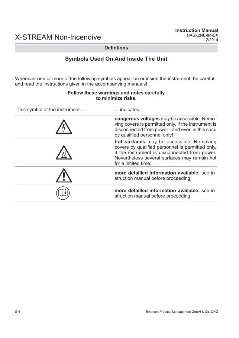
Symbols Used On And Inside The Unit
This symbol at the instrument ... ... indicates
dangerous voltages may be accessible. Remo-ving covers is permitted only, if the instrument is disconnected from power - and even in this case by qualifi ed personnel only!hot surfaces may be accessible. Removing covers by qualifi ed personnel is permitted only, if the instrument is disconnected from power. Nevertheless several surfaces may remain hot for a limited time.
more detailled information available: see in-struction manual before proceeding!
more detailled information available: see in-struction manual before proceeding!
Wherever one or more of the following symbols appear on or inside the instrument, be careful and read the instructions given in the accompanying manuals!
Follow these warnings and notes carefully to minimize risks.
Defi ntions

Emerson Process Management GmbH & Co. OHG S-5
X-STREAM Non-IncendiveInstruction ManualHASX2NE-IM-EX12/2014
SS
afet
y In
stru
ctio
ns
This symbol used in the manual ... ... means
dangerous voltages may be exposed
hot surfaces may be exposed
possible danger of explosion
toxic substances may be present
substances harmful to health may be present
indicates notes relating to heavy instruments
electrical components may be destroyed by electrostatic discharges
units must be disconnected from the power source
indicates special instructions or information for operation at low temperatures.
indicates basic conditions or procedures are being described.This symbol may also indicate information impor-tant for achieving accurate measurements.
Defi nitions
Where one or more of the following symbols appear within this manual, carefully read the rela-ted information and instructions!
Strictly observe the given warnings, instructions and information to minimize hazards!
Symbols Used Within This Manual
Emerson Process Management GmbH & Co. OHGS-6
X-STREAM Non-IncendiveInstruction Manual
HASX2NE-IM-EX12/2014
Intended Use Statement
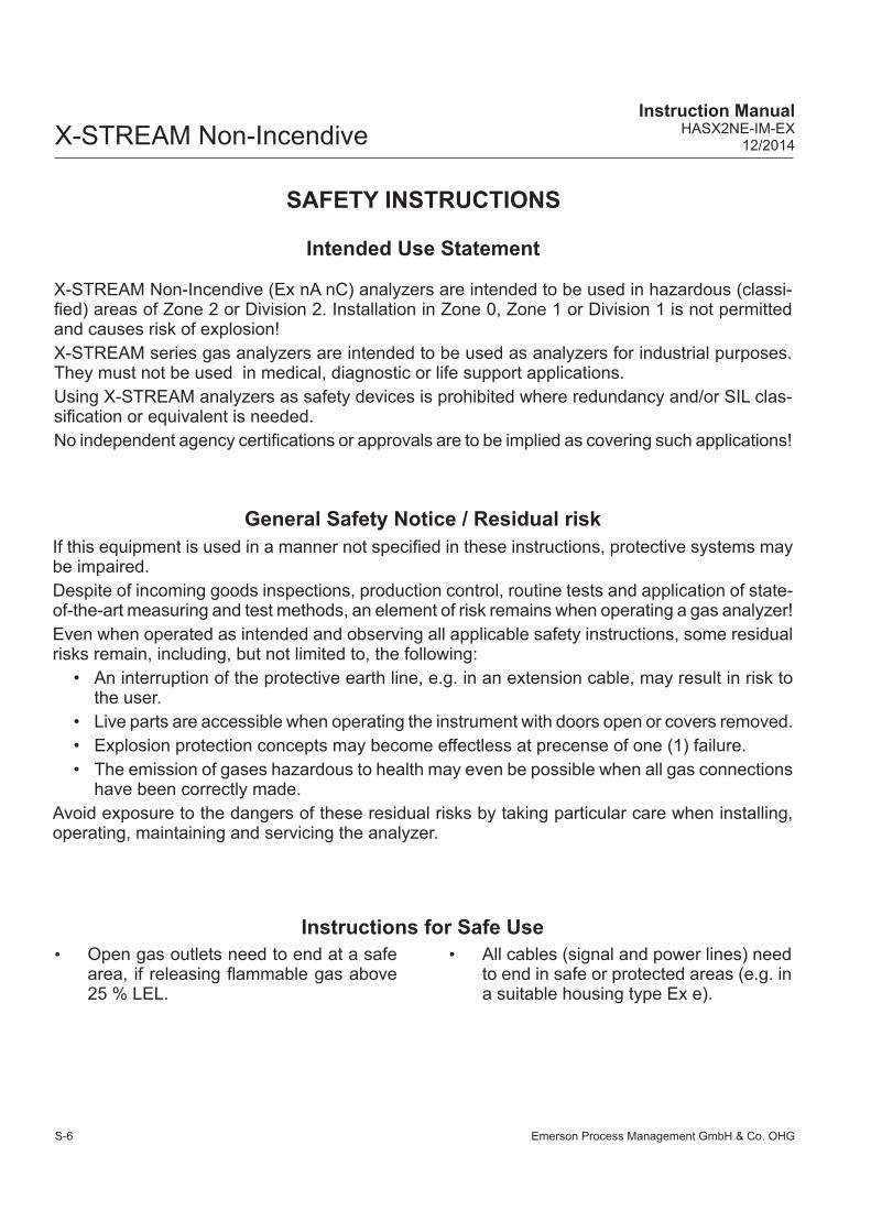
X-STREAM Non-Incendive (Ex nA nC) analyzers are intended to be used in hazardous (classi-fi ed) areas of Zone 2 or Division 2. Installation in Zone 0, Zone 1 or Division 1 is not permitted and causes risk of explosion! X-STREAM series gas analyzers are intended to be used as analyzers for industrial purposes. They must not be used in medical, diagnostic or life support applications.Using X-STREAM analyzers as safety devices is prohibited where redundancy and/or SIL clas-sifi cation or equivalent is needed. No independent agency certifi cations or approvals are to be implied as covering such applications!
General Safety Notice / Residual riskIf this equipment is used in a manner not specifi ed in these instructions, protective systems may be impaired. Despite of incoming goods inspections, production control, routine tests and application of state-of-the-art measuring and test methods, an element of risk remains when operating a gas analyzer! Even when operated as intended and observing all applicable safety instructions, some residual risks remain, including, but not limited to, the following:
• An interruption of the protective earth line, e.g. in an extension cable, may result in risk to the user.
• Live parts are accessible when operating the instrument with doors open or covers removed.• Explosion protection concepts may become effectless at precense of one (1) failure.• The emission of gases hazardous to health may even be possible when all gas connections
have been correctly made.Avoid exposure to the dangers of these residual risks by taking particular care when installing, operating, maintaining and servicing the analyzer.
SAFETY INSTRUCTIONS
Instructions for Safe Use• Open gas outlets need to end at a safe
area, if releasing fl ammable gas above 25 % LEL.
• All cables (signal and power lines) need to end in safe or protected areas (e.g. in a suitable housing type Ex e).

Emerson Process Management GmbH & Co. OHG S-7
X-STREAM Non-IncendiveInstruction ManualHASX2NE-IM-EX12/2014
SS
afet
y In
stru
ctio
ns
Safety Instructions
This manual covers aspects specifi c for using Non-Incendive (Ex nA nC) X-STREAM gas analy-zers in hazardous (classifi ed) areas, only.For comprehensive information on operating and maintain/service the instrument in a safe manner it is MANDATORY to read all additional instruction manuals, if not provided as printed version, see the accompanying CD-ROM for an electronic version (PDF)!
The following instruction manuals are available, referenced within and to be read in conjunction with this manual at hand:HASX2E-IM-HS X-STREAM X2 series instruction manualHASICx-IM-H Infallible containment instruction manual (if applicable)
Contact your local service center or sales offi ce when missing documents.
SAVE ALL INSTRUCTION MANUALS FOR FUTURE USE!
Additional Literature
In-depth specialist knowledge is an absolutely necessary condition for working with and on the analyzer.
Authorized personnel for installing, operating, servicing and maintaining the analyzer are instructed and trained qualifi ed personnel of the operating company and the manufacturer.
It is the responsibility of the operating company to• train staff,• observe safety regulations,• follow the instruction manual.
Operators must• have been trained,• have read and understood all relevant sections of the instruction manual before commencing
work,• know the safety mechanisms and regulations.
To avoid personal injury and loss of property, do not install, operate, maintain or service this instru-ment before reading and understanding this instruction manual and receiving appropriate training.
Authorized Personnel

Emerson Process Management GmbH & Co. OHGS-8
X-STREAM Non-IncendiveInstruction Manual
HASX2NE-IM-EX12/2014
Safety Instructions
General
GENERAL SAFETY NOTE
Consider the subsequently given safety instructions, all safety instructions given in the separate chapters as well as all safety instructions of the associated manuals!
EXPLOSION HAZARD
Consider all applicable standards and legislative requirements during installation, startup, operation, maintenance and demounting this analyzer.Read, understand and consider all instructions given in this manual and the associated manuals of the analyzer before starting to work with this analyzerFailure to follow may cause explosion, property damage and/or personal injury or death!
EXPLOSION HAZARD BY AREA CLASSIFICATION
Analyzers subject of this manual are permitted to be installed in hazardous areas of Zone 2 or Division 2 classifi cation only!Failure to follow may cause explosion!
EXPLOSION HAZARD BY DAMAGES
Do NOT operate damaged analyzers!Take out of operation and take care for proper maintenance or repair!Failure to follow may cause explosion, physical injury or death!
Emerson Process Management GmbH & Co. OHG S-9
X-STREAM Non-IncendiveInstruction ManualHASX2NE-IM-EX12/2014
SS
afet
y In
stru
ctio
ns
Safety Instructions
EXPLOSION HAZARD WHEN OPEN
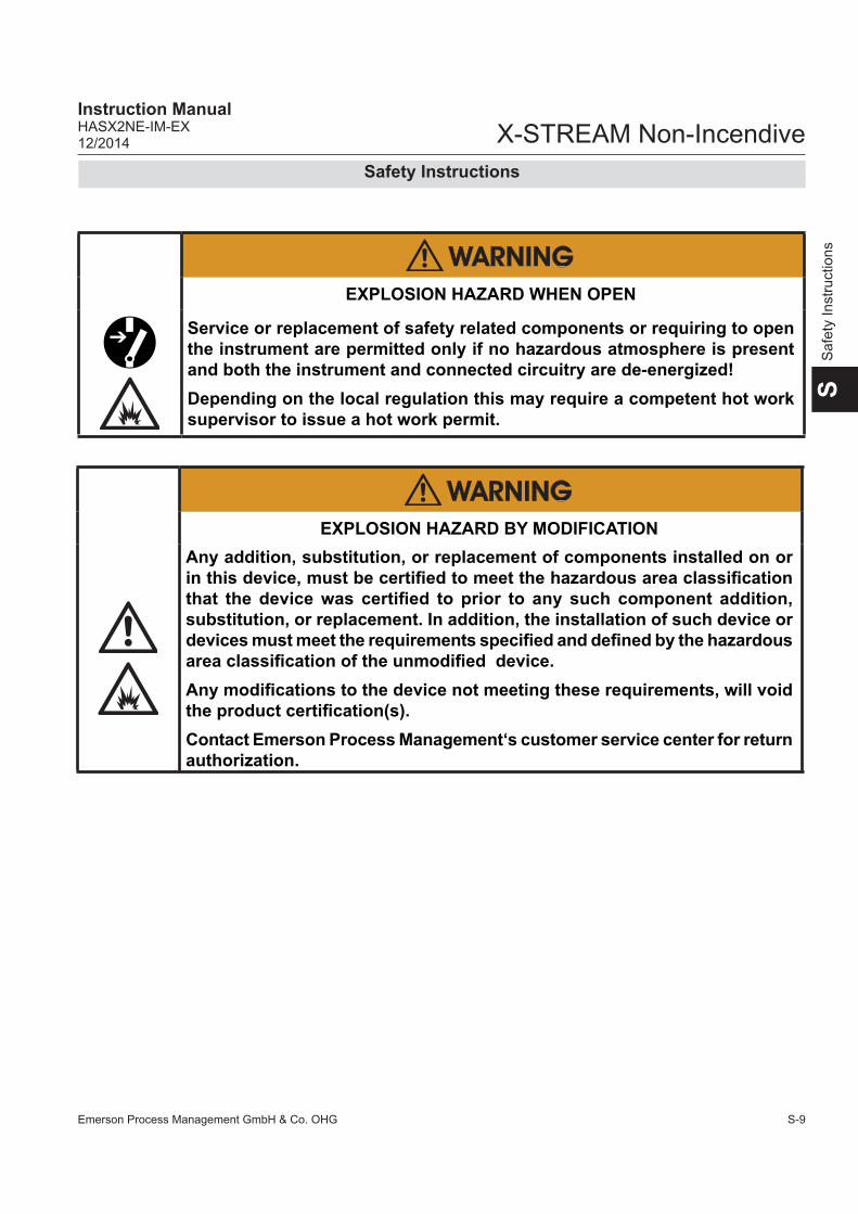
Service or replacement of safety related components or requiring to open the instrument are permitted only if no hazardous atmosphere is present and both the instrument and connected circuitry are de-energized!Depending on the local regulation this may require a competent hot work supervisor to issue a hot work permit.
EXPLOSION HAZARD BY MODIFICATION
Any addition, substitution, or replacement of components installed on or in this device, must be certifi ed to meet the hazardous area classifi cation that the device was certifi ed to prior to any such component addition, substitution, or replacement. In addition, the installation of such device or devices must meet the requirements specifi ed and defi ned by the hazardous area classifi cation of the unmodifi ed device. Any modifi cations to the device not meeting these requirements, will void the product certifi cation(s).Contact Emerson Process Management‘s customer service center for return authorization.

Emerson Process Management GmbH & Co. OHGS-10
X-STREAM Non-IncendiveInstruction Manual
HASX2NE-IM-EX12/2014
Safety Instructions
EXPLOSION HAZARD
The analyzers provide a protective earth terminal. To prevent electrical shock hazards the instruments must be connected to a protective earth. Therefore the instruments must be connected to power by using a three wire power cable with earth conductor!Any interruption of the earth connector inside or outside the instrument or disconnecting the earth terminal may cause potential electrical shock hazard!Failure to follow may cause explosion, property damage and personal injury or death!
ELECTRICAL SHOCK HAZARD
Installation, and connecting mains and signal cables are subject to qualifi ed personnel only, taking into account all applicable standards and legislative requirements!Failure to follow may cause warranty invalidation, property damage and/or personal injury or death! Connecting mains and signal cables to internal srew terminals requires working at open housing near life parts!Installation of this instrument is subject to qualifi ed personnel only, familiar with the resulting potential risks!The gas analyzers do not provide a mains power switch and are operable when connected to power.The gas analyzers do not provide a mains switch! A mains switch or circuit breaker (to comply with IEC 60947-1 /-3) has to be provided in the building installation. This switch has to be installed near by analyzer, must be easily operator accessible and has to be assigned as disconnector for the analyzer.

Emerson Process Management GmbH & Co. OHG S-11
X-STREAM Non-IncendiveInstruction ManualHASX2NE-IM-EX12/2014
SS
afet
y In
stru
ctio
ns
Safety Instructions
EXPLOSION AND ELECTRICAL SHOCK HAZARD
All cables (power and signal) must end (be connected) in either a safe (non-hazardous) area or in a protecting enclosure (e.g. Ex e junction box)!The power and signal cables must be separated by a distance of minimum 1 cm (0.4 in) inside and outside the analyzer!
EXPLOSION HAZARD
Startup, operation and service must not be performed before reading and understanding all instructions!Especially all warnings in this and the associated manuals have to be considered! Inspection, maintenance and service must be carried out considering all related standards e.g. for „Inspection and maintenance of electrical installations in hazardous areas“ or „Equipment repair, overhaul and reclamation“.

Emerson Process Management GmbH & Co. OHGS-12
X-STREAM Non-IncendiveInstruction Manual
HASX2NE-IM-EX12/2014
Startup
EXPLOSION HAZARD
Before applying power and signals:• Verify for proper installation• Verify that all covers and plugs are properly installed and in place!• Verify that all gas connections are tight.Violation may result in explosion, personal injury or death!
Safety Instructions
EXPLOSION HAZARD WHEN OPEN
Do NOT operate the instrument with doors or covers open! This is permitted only when no hazardous atmosphere is present! Depending on the local regulation, this may require a competent hot work supervisor to issue a hot work permit.Violation may cause an explosion hazard!
OPERATION AT LOW TEMPERATURES
When operating an instrument at temperatures below 0 °C (32 °F), do NOT apply gas nor operate the internal pump before the warmup time has elapsed!Violation may result in condensation inside the gas paths or damaged pump diaphragm!
HIGH TEMPERATURES HAZARD
While working at internal components hot surfaces may be accessible, even after the instrument has been disconnected from power!
Emerson Process Management GmbH & Co. OHG S-13
X-STREAM Non-IncendiveInstruction ManualHASX2NE-IM-EX12/2014
SS
afet
y In
stru
ctio
ns
Safety Instructions
EXPLOSION HAZARD AND HARMFUL TO HEALTH GASES
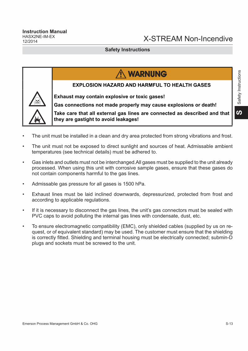
Exhaust may contain explosive or toxic gases! Gas connections not made properly may cause explosions or death!Take care that all external gas lines are connected as described and that they are gastight to avoid leakages!
• The unit must be installed in a clean and dry area protected from strong vibrations and frost.
• The unit must not be exposed to direct sunlight and sources of heat. Admissable ambient temperatures (see technical details) must be adhered to.
• Gas inlets and outlets must not be interchanged.All gases must be supplied to the unit already processed. When using this unit with corrosive sample gases, ensure that these gases do not contain components harmful to the gas lines.
• Admissable gas pressure for all gases is 1500 hPa.
• Exhaust lines must be laid inclined downwards, depressurized, protected from frost and according to applicable regulations.
• If it is necessary to disconnect the gas lines, the unit’s gas connectors must be sealed with PVC caps to avoid polluting the internal gas lines with condensate, dust, etc.
• To ensure electromagnetic compatibility (EMC), only shielded cables (supplied by us on re-quest, or of equivalent standard) may be used. The customer must ensure that the shielding is correctly fi tted. Shielding and terminal housing must be electrically connected; submin-D plugs and sockets must be screwed to the unit.

Emerson Process Management GmbH & Co. OHGS-14
X-STREAM Non-IncendiveInstruction Manual
HASX2NE-IM-EX12/2014
Safety Instructions

Emerson Process Management GmbH & Co. OHG 1-1
X-STREAM Non-IncendiveInstruction ManualHASX2NE-IM-EX12/2014
1Te
chni
cal D
escr
iptio
n
Chapter 1Technical Description
1.1 Analyzervariations covered by this manual
1.2 Application and Principle of OperationX-STREAM non-incendive gas analyzers enable the measurement of gas components in hazardous areas (Ex zone 2 or Division 2) without the need of additional external pro-tective equipment: They have been designed in a way to be built of selected components, which do not create arcs, sparks nor hot spots under normal ope-rating conditions. Thus they cannot ignite a surrounding explosive atmoshere, even if it penetrates the analyzer enclosure. These protection methods (summarized un-der the topic „non-incendive“) are specifi ed by
standard CAN/CSA 60079-15. Thus the ana-lyzers can be operated in hazardous areas classifi ed Divison 2 (Div. 2) North-American standards (CSA-C/US approval).In these areas explosive atmosphere is not likely to exist under normal operating condi-tions, and if so, for short time periods only.
For a comprehensive list of applicable certi-fi cates visit our website at
www.emersonprocess.com.
X-STREAM XLFN X-STREAM X2 series single compartment analyzerX-STREAM XXFN X-STREAM X2 series dual compartment analyzer
This manual covers 2 variations of X-STREAM X2 Fieldhousing (X2XF) Gasanalyzers with pro-tection concept "Non-Incendive" (Ex nA nC):

Emerson Process Management GmbH & Co. OHG1-2
X-STREAM Non-IncendiveInstruction Manual
HASX2NE-IM-EX12/2014
1.2 Application and Principle of Operation
EXPLOSION HAZARD BY FLAMMABLE GASES
Flammable Gases must be introduced into INFALLIBLE CONTAINMENTS ONLY, to avoid leakage into internal analyzer housing!Such containments are provided on request.
Permitted sample gasesDue to the limitation of use to Zone 2 envi-ronments only, measuring fl ammable gases is by default not permitted for non-incendive analyzers: Standard tubings (containments) would enable those gases to pass off into the housing in case of leakages. Together with the air being present, this would form an explosive
mixture. And, as a result of the tight enclosure and therefore missing exchange with the sur-rounding atmosphere, the explosive mixture would be present for long time periods. Thus the categorization of the internal compart-ment of the non-incendive X-STREAM ana-lyzer would be no more according to Zone 2 (Div 2), but Zone 0 (Div 1), requiring special protection methods!
To enable measuring fl ammable gases with non-incendive X-STREAM analyzers, Emer-son Process Management has designed special, so called Infallible Containments: These are gas paths, considered to be „technically tight“ due to the construction ( page 1-8). Using infallible containments properly avoids release of sample gas into the analyzer, and the formation of internal explosive atmosphere.

Emerson Process Management GmbH & Co. OHG 1-3
X-STREAM Non-IncendiveInstruction ManualHASX2NE-IM-EX12/2014
1Te
chni
cal D
escr
iptio
n
1.3 Technical Data
1.3 Technical Data1.3.1 Installation Site and Protection Method
Test samples have been approved by independent test institutes according to the relevant stan-dards and found to comply with the requirements. The certifi cates can be viewed in the appendix of this manual ( page A-1).
Admissible ValuesHumidity (non-condensing)
< 90 % RH at +20 °C (68 °F)< 70 % RH at +40 °C (104 °F)
Degree of pollution 2Installation category IIElevation 0 to 2000 m (6560 ft) above sea levelAmbient atmosphere Non corrosive
Protection Concept: Ex nACNorth America (CSA-c/us)
Hazardous area Zone 2, Gas Div 2Classifi cation Class I, Zone 2, Gas,
AEx nAC IIC T4Ex nAC IIC T4
Class I, Div 2, Group ABCD
Temperature class T4 T4Underlying stan-dards
CAN/CSA-E60079-0: 02 (R2006) CAN/CSA-E60079-15:02 (R2006) ANSI/ISA-12.00.01-2002 (IEC 60079-0 Mod)ANSI/ISA-12.22.01-2002 (IEC 60079-1 Mod)UL 60079-15:2009
CSA C22.2 No 213-M1987ISA 12.12.01-2007
Site of installation:

Emerson Process Management GmbH & Co. OHG1-4
X-STREAM Non-IncendiveInstruction Manual
HASX2NE-IM-EX12/2014
1.3 Technical Data
1.3.2 Nameplate Label
Fig. 1-1: Nameplate Label Details
Area Description Area DescriptionThe analyzer´s electrical data, manufacturing data and serial number
Manufacturer address
Additional warning: Do not open the instrument when energized!
Certifi cation Data EU (ATEX) North America
Area classifi cationII other than mines 3 Category 3 Equipm. (Zone 2) G for explosive Gas atmosphere
Class I Flammable gases, vapor, liquidsDiv. 2 Equipment for Div. 2Grp. ABCD All Class I gasesT4 Temperature Class (135 °C)Class I Flammable gases, vapor, liquidsZone 2 Equipment for Zone 2
Protection concepts
Ex Explosion protected nA nC non-sparking, enclosed breakIIC Group II, Gas Group C T4 Temperature Class (135 °C)Gc Equipment Protection LevelTamb Ambient Temperature RangeIP66, Type 4X Enclosure Rating (Outdoor use)
AEx, Ex Explosion protected nAC non-sparking, enclosed breakIIC Group II, Gas Group C T4 Temperature Class (135 °C)Tamb Ambient Temperature RangeIP66, Type 4X Enclosure Rating (Outdoor use)
Emerson Process Management GmbH & Co. OHG 1-5
X-STREAM Non-IncendiveInstruction ManualHASX2NE-IM-EX12/2014
1Te
chni
cal D
escr
iptio
n
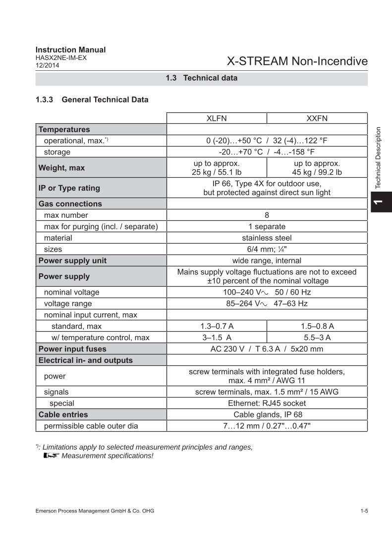
1.3.3 General Technical Data
1.3 Technical data
XLFN XXFNTemperatures
operational, max.*) 0 (-20)…+50 °C / 32 (-4)…122 °Fstorage -20…+70 °C / -4…-158 °F
Weight, max up to approx. 25 kg / 55.1 lb
up to approx. 45 kg / 99.2 lb
IP or Type rating IP 66, Type 4X for outdoor use, but protected against direct sun light
Gas connectionsmax number 8max for purging (incl. / separate) 1 separatematerial stainless steelsizes 6/4 mm; 1⁄4"
Power supply unit wide range, internal
Power supply Mains supply voltage fl uctuations are not to exceed ±10 percent of the nominal voltage
nominal voltage 100–240 V 50 / 60 Hzvoltage range 85–264 V 47–63 Hznominal input current, max
standard, max 1.3–0.7 A 1.5–0.8 Aw/ temperature control, max 3–1.5 A 5.5–3 A
Power input fuses AC 230 V / T 6.3 A / 5x20 mmElectrical in- and outputs
power screw terminals with integrated fuse holders, max. 4 mm² / AWG 11
signals screw terminals, max. 1.5 mm² / 15 AWGspecial Ethernet: RJ45 socket
Cable entries Cable glands, IP 68permissible cable outer dia 7…12 mm / 0.27"…0.47"
*): Limitations apply to selected measurement principles and ranges, Measurement specifi cations!
Emerson Process Management GmbH & Co. OHG1-6
X-STREAM Non-IncendiveInstruction Manual
HASX2NE-IM-EX12/2014
1.4 Dimensions
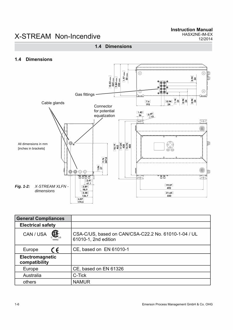
1.4 Dimensions
All dimensions in mm [inches in brackets]
Cable glands
Gas fi ttings
Connector for potentialequalization
Fig. 1-2: X-STREAM XLFN - dimensions
General CompliancesElectrical safety
CAN / USA
CSA-C/US, based on CAN/ CSA-C22.2 No. 61010-1-04 / UL 61010-1, 2nd edition
Europe CE, based on EN 61010-1Electromagnetic compatibility
Europe CE, based on EN 61326Australia C-Tickothers NAMUR

Emerson Process Management GmbH & Co. OHG 1-7
X-STREAM Non-IncendiveInstruction ManualHASX2NE-IM-EX12/2014
1Te
chni
cal D
escr
iptio
n
Fig. 1-3: X-STREAM XXFN - dimensions
All dimensions in mm [inches in brackets]
Cable glands
Connector for potentialequalization
Gas fi ttings
eqqqqqqqqqqqqquuuuuuu
1.4 Dimensions

Emerson Process Management GmbH & Co. OHG1-8
X-STREAM Non-IncendiveInstruction Manual
HASX2NE-IM-EX12/2014
Gas components Non-fl ammable gases resp. gas mixtures; concentration does not exceed LEL (lower explosion limit) ORfl ammable gases passed into an infallible containment only!
Maximum sample gas pressure
Atmospheric pressure or <1500 hPa at normal ambient pressure, depen-ding on the integrated measuring principle (see related X-STREAM series instruction manual)
Sample gas fl ow Depending on measuring principle (see related X-STREAM series instruc-tion manual)
1.5 Gas Specifi cations
1.5 Gas Specifi cations
EXPLOSION HAZARD BY FLAMMABLE GASES
Flammable Gases must be introduced into INFALLIBLE CONTAINMENTS ONLY, to avoid leakage into internal analyzer housing!Such containments are provided on request.

Emerson Process Management GmbH & Co. OHG 1-9
X-STREAM Non-IncendiveInstruction ManualHASX2NE-IM-EX12/2014
1Te
chni
cal D
escr
iptio
n
1.6 Measurements Specifi cations
Sample gas components and measuring ranges (standard confi gurations)In total, more than 60 gases are detectable, so the following table gives an overview only. Consult with Emerson for gases / confi gurations not listed. Not all data is applicable to all analyzer variations. The sample gas(es) and measuring ranges for your specifi c analyzer are given by the order acknowledgement and on the analyzer's name plate label.
1.6 Measurements Specifi cations
Tab. 1-1: Gas Components and Measuring Ranges, examples
1 Dew point below ambient temperature
2 Higher concentrations decrease sensor lifetime
3 Daily zero calibration: Re- quired for ranges below low-est standard specs range
4 Special "refi nery" application with 0–1% H2 in N2 available
5 see Table 1-5
Special Specs or Conditions
Standard Specs (Tables 1-2 – 1-4)
Gas component PrincipleLowestRange
LowestRange
Highest Range
Acetone 1 CH3COCH3 UV 0–400 ppm 0–3 %Acetone 1 CH3COCH3 IR 0–500 ppm 0–3 %Acetylene C2H2 IR 0–3 % 0–100 %Ammonia NH3 IR 0–100 ppm 0–100 %Argon Ar TCD 0–50 % 0–100 %Carbon dioxide CO2 IR 0–5 ppm 5 0–50 ppm 0–100 %Carbon monoxide CO IR 0–10 ppm 5 0–50 ppm 0–100 %Chlorine Cl2 UV 0–300 ppm 0–100 %Ethane C2H6 IR 0–1000 ppm 0–100 %Ethanol 1 C2H5OH IR 0–1000 ppm 0–10 %Ethylene C2H4 IR 0–400 ppm 0–100 %Helium He TCD 0–10 % 0–100 %Hexane 1 C6H14 IR 0–100 ppm 0–10 %Hydrogen 4 H2 TCD 0–1 % 0–100 %Hydrogen Sulfi de H2S UV 0–2 % 0–10 %Hydrogen Sulfi de H2S IR 0–10 % 0–100 %Methane CH4 IR 0–100 ppm 0–100 %Methanol 1 CH3OH IR 0–1000 ppm 0–10 %n–Butane C4H10 IR 0–800 ppm 0–100 %Nitrogen dioxide 1 NO2 UV 0–25 ppm 3 0–50 ppm 0–10 % Nitrogen monoxide NO IR 0–100 ppm 0–100 %Nitrous oxide N2O IR 0–100 ppm 0–100 %Oxygen O2 electrochem. 0–5 % 0–25 % 2
Oxygen O2 paramagn. 0–1 % 0–100 %Propane C3H8 IR 0–1000 ppm 0–100 %Propylene C3H6 IR 0–400 ppm 0–100 %Sulfur dioxide SO2 UV 0–25 ppm 3 0–50 ppm 0–1 % Sulfur dioxide SO2 IR 0–1 % 0–100 % Sulfur hexafl uoride SF6 IR 0–5 ppm 3 0–20 ppm 0–2 %Toluene 1 C7H8 UV 0–300 ppm 0–5 %Vinyl chloride C2H3Cl IR 0–1000 ppm 0–2 %Water vapor 1 H2O IR 0–1000 ppm 0–8 % Water vapor, Trace 1 H2O capacitive 0–100 ppm 0–3000 ppm

Emerson Process Management GmbH & Co. OHG1-10
X-STREAM Non-IncendiveInstruction Manual
HASX2NE-IM-EX12/2014
1.6 Measurements Specifi cations
NDIR/UV/VIS Thermal Conductivity (TCD)Detection limit (4 ) 1 4 ≤ 1 % ≤ 1 % Linearity 1 4 ≤ 1 % ≤ 1 % Zero-point drift 1 4 ≤ 2 % per week ≤ 2 % per weekSpan (sensitivity) drift 1 4 ≤ 0.5 % per week ≤ 1 % per week Repeatability 1 4 ≤ 1 % ≤ 1 % Response time (t90) 3 4 s ≤ t90 ≤ 7 s 5 15 s ≤ t90 ≤ 30 s 6
Permissible gas fl ow 0.2–1.5 l/min. 0.2–1.5 l/min. 11
Infl uence of gas fl ow 1 4 ≤ 0.5 % ≤ 1 % 11
Maximum gas pressure 8 ≤ 1500 hPa abs. (≤ 7 psig) ≤ 1500 hPa abs. (≤ 7 psig) Infl uence of pressure 2
– At constant temperature ≤ 0.10 % per hPa ≤ 0.10 % per hPa – With pressure compensation 7 ≤ 0.01 % per hPa ≤ 0.01 % per hPa
Permissible ambient temperature 9 0 (-20) to +50 °C (32 (-4) to 122 °F) 0 (-20) to +50 °C (32 (-4) to 122 °F) Infl uence of temperature 1 13
(at constant pressure)– On zero point ≤ 1 % per 10 K ≤ 1 % per 10 K– On span (sensitivity) ≤ 5 % (0 to +50 °C / 32 to 122 °F) ≤ 1 % per 10 K
Thermostat control 6 12 none / 60 °C (140 °F) 5 none / 60 °C (140 °F) 10 Warm-up time 6 15 to 50 minutes 5 approx. 50 minutes
Note! 1 psi = 68.95 hPa1 Related to full scale2 Related to measuring value3 From gas analyzer inlet at gas fl ow of 1.0 l/min
(electronic damping = 0 s)4 Constant pressure and temperature
5 Dependent on integrated photometer bench6 Depending on measuring range7 Pressure sensor is required8 Limited to atmospheric if internal sample pump9 Temperatures below 0 °C (-4 °F) with thermostat
control only
10 Thermost. controlled sensor: 75 °C (167 °F)11 Flow variation within ± 0.1 l/min12 Optional thermostatically controlled box with
temperature 60 °C (140 °F)13 Temperature variation: ≤ 10 K per hour
Note! 1 psi = 68.95 hPa1 If installed in series to another measurement system, e. g. IR channel
Trace Moisture (tH2O)Measurement range -100 to -10 °C dew point (0…100–3000 ppm) Measurement accuracy ±2 °C dew pointRepeatability 0.5 °C dew point Response time (t95) 5 min (dry to wet)Operating humidity 0 to 100 % r.h.Sensor operating temperature -40 to +60 °CTemperature coeffi cient Temperature compensated across operating temperature rangeOperating pressure Depending on sequential measurement system, see analyzer specifi cation 1
max. 1500 hPa abs / 7 psigFlow rate Depending on sequential measurement system, see analyzer specifi cation 1
0.2 to 1.5 l/min
Tab. 1-2: IR, UV, VIS, TCD - Measurement Performance Specifi cations
Tab. 1-3: Trace Moisture - Measurement Performance Specifi cations
Note! Do not calibrate, see special calibration notes in chapter 4!

Emerson Process Management GmbH & Co. OHG 1-11
X-STREAM Non-IncendiveInstruction ManualHASX2NE-IM-EX12/2014
1Te
chni
cal D
escr
iptio
n
1.6 Measurements Specifi cations
1 Related to full scale2 Related to measuring value3 From gas analyzer inlet at gas fl ow of 1.0 l/min
(electronic damping = 0 s)4 Constant pressure and temperature5 n. a.6 Pressure sensor is required
7 Limited to atmospheric if internal sample pump8 Temperatures below 0 °C (-4 °F) with thermostat
control only9 n. a.
10 For ranges 0–5…100 % and fl ow 0.5…1.5 l/min
11 Optional thermostatically controlled sensor with temperature 60 °C (140 °F)
12 Temperature variation: ≤ 10 K per hour13 No sudden pressure surge allowed
Oxygen Sensors
Paramagnetic (pO2) Electrochemical (eO2)Detection limit (4 ) 1 4 ≤ 1 % ≤ 1 % Linearity 1 4 ≤ 1 % ≤ 1 % Zero-point drift 1 4 ≤ 2 % per week ≤ 2 % per week Span (sensitivity) drift 1 4 ≤ 1 % per week ≤ 1 % per weekRepeatability 1 4 ≤ 1 % ≤ 1 % Response time (t90) 3 < 5 s approx. 12 sPermissible gas fl ow 0.2–1.5 l/min 0.2–1.5 l/min.Infl uence of gas fl ow 1 4 ≤ 2 % 10 ≤ 2 %Maximum gas pressure 7 ≤ 1500 hPa abs. (≤ 7 psig) 13 ≤ 1500 hPa abs. (≤ 7 psig)Infl uence of pressure 2
– At constant temperature ≤ 0.10 % per hPa ≤ 0.10 % per hPa– With pressure compensation 6 ≤ 0.01 % per hPa ≤ 0.01 % per hPa
Permissible ambient temperature 8 0(-20) to +50 °C (32 (4) to 122 °F) 5 to +45 °C (41 to 113 °F)Infl uence of temperature 1 12 (at constant pressure)
– On zero point ≤ 1 % per 10 K ≤ 1 % per 10 K– On span (sensitivity) ≤ 1 % per 10 K ≤ 1 % per 10 K
Thermostat control 60 °C (140 °F) 11 noneWarm-up time Approx. 50 minutes -
Note! 1 psi = 68.95 hPa
Tab. 1-4: Oxygen - Measurement Performance Specifi cations
Note 1!Not all data listed are applicable to all analyzer versions (e.g. 60 °C thermostatically controlled box is not available for electrochemical and trace oxygen).Note 2!For NDIR/UV/VIS measurements, take into account that • sample gas may diffuse or be released by leakages into the analyzer enclosure• if existent in the analyzer surroundings, the component to be measured may enter the enclosure. Concentrations then may increase inside the enclosure. High concentrations of the component to be measured inside the enclosure may infl uence the measurement by unintended absorption, which could cause drift of the measurement. A remedy for this issue is to purge the housing with gas not containing the component of interest.

Emerson Process Management GmbH & Co. OHG1-12
X-STREAM Non-IncendiveInstruction Manual
HASX2NE-IM-EX12/2014
1 Related to full scale2 Constant pressure and temperature3 Within 24 h; daily zero calibration requested4 Within 24 h; daily span calibration recommended
5 Related to measuring value6 Temperature variation: ≤ 10 K per hour7 From gas analyzer inlet at gas fl ow of 1.0 l/min8 Barometric pressure sensor is required
9 Whichever value is higher10 Limited to atmospheric if internal sample pump
0–10…< 50 ppm CO0–5…< 50 ppm CO2
Detection limit (4 ) 1 2 < 2 %Linearity 1 2 < 1 %Zero-point drift 1 2 3 < 2 % resp. < 0.2 ppm 9
Span (sensitivity) drift 1 2 4 < 2 % resp. < 0.2 ppm 9
Repeatability 1 2 < 2 % resp. < 0.2 ppm 9 Response time (t90) 7 < 10 sPermissible gas fl ow 0.2–1.5 l/min.Infl uence of gas fl ow 1 2 < 2%Maximum gas pressure 10 ≤ 1500 hPa abs. (≤ 7 psig)Infl uence of pressure 5
– At constant temperature ≤ 0.1 % per hPa– With pressure compensation 8 ≤ 0.01 % per hPa
Permissible ambient temperature +15 to +35 °C (59 to 95 °F) +5 to +40 °C (41 to 104 °F)Infl uence of temperature 6
(at constant pressure)– On zero point < 2 % per 10 K resp. < 0.2 ppm per 10 K 9
– On span (sensitivity) < 2 % per 10 K resp. < 0.2 ppm per 10 K 9
Thermostat control none 60 °C (140 °F)Note! 1 psi = 68.95 hPa
1.6 Measurements Specifi cations
Tab. 1-5: Special Performance Specifi cations for Gas Purity Measurements
Emerson Process Management GmbH & Co. OHG 1-13
X-STREAM Non-IncendiveInstruction ManualHASX2NE-IM-EX12/2014
1Te
chni
cal D
escr
iptio
n
1.5 Measurement Specifi cations
1.7 Infallible ContainmentsA containment is the entirety of the gas paths inside the analyzer.Infallible Containments are characterized by the fact, that no unintended release of gas into the analyzer can happen.This is based on connections being velded, soldered or designed as glass-to-metal con-nections resp. eutectic or similar methods.Containments complying to the conditions described above are called "in the long run technically tight". This term is used, because total tightness for gases is not achievable. Technical tightness is also conceded to me-tallically tightening tube fi ttings, such as e.g. used with Emerson Process Managements gas analyzers.Such equipment remain technically tight, if the tightness is based on design, or if it is ensured
on a permanent basis by maintenance and monitoring. In case of X-STREAM gas analyzers, the function test for infallible containments is performed according to the standard EN 60079-2. X-STREAM non-incendive analyzers can be used for measuring flammable gases, if the gas paths for sample gas (and fl ammab-le calibration gases) are designed as infallible containments, currently available for thermal conductivity measurements only.
1.8 Instructions for safe use• Open gas outlets need to end at a safe
area, if releasing fl ammable gas above 25 % LEL.
• All cables (signal and power lines) need to end in safe or protected areas (e.g. in a suitable housing type Ex e).

Emerson Process Management GmbH & Co. OHG1-14
X-STREAM Non-IncendiveInstruction Manual
HASX2NE-IM-EX12/2014

Emerson Process Management GmbH & Co. OHG 2-1
X-STREAM Non-IncendiveInstruction ManualHASX2NE-IM-EX12/2014
2In
stal
latio
n
Chapter 2Installation
Up to three manuals:- X-STREAM X2 series manual- This manual addendum- Infallible containment manual*)
EXPLOSION HAZARD WHEN MISSING INFORMATION
Compare the content of your package with the pictures below. Call your local sales offi ce if something is missing, and DO NOT continue to install your analyzer, until all parts are at hand!
Fig. 2-1: Scope of Supply
2.1 Scope of Supply
*) For instruments with infallible containment (option) only!
Analyzer Trace oxygen cell (if applicable)
USB stick
This chapter describes the proper installation procedure for the Non-Incendive X-STREAM ana-lyzer version.
On receipt, check the packaging and its contents thoroughly for damage. Inform the carrier immediately of any damage to packaging or contents, and keep dama-ged parts until clarifi cation. Store the instrument at a dry and clean place, considering the acceptable environmental conditions. We recommend to keep the packaging available for future transportation, because only the ori-ginal packaging ensures proper protection!

Emerson Process Management GmbH & Co. OHG2-2
X-STREAM Non-IncendiveInstruction Manual
HASX2NE-IM-EX12/2014
2.2 General Safety Instructions
EXPLOSION HAZARD
Consider all applicable standards and legislative requirements when installing the analyzer, and connecting power and signal cables. Take care of the relevant installation standards, as there are (but not limited to) e.g. EN 60079-14 (Europe), National Electrical Code (NEC-NFPA 70; USA), Canadian Electrical Code (CEC; Canada), IEC 60079-14 (International), and all corresponding standards.Consider all instructions given in this, and all associated analyzer manuals!Read and understand all instructions given in the manuals before beginning to install the analyzer!Failure to follow the instructions may cause explosion, property damage and personal injury or death!
EXPLOSION HAZARD
Installing this instrument requires opening the housing and working at open instrument. This is permitted only if no hazardous atmosphere is present, and the instrument and all connected external ciruitry is de-energized!X-STREAM gas analyzers do not provide a power switch and are operable when connected to power!Depending on the local legislation, this may require a hot work permit to be issued.
EXPLOSION HAZARD BY GASES
X-STREAM analyzers utilize not only sample gas but one or more pressurized carrier gases and/or calibration gases.If external equipment (e.g. a fl owmeter for fl ow control) is required, legislative requirements and instructions for installation in hazardous (classifi ed) areas must be considered.
2.2 General Safety Instructions

Emerson Process Management GmbH & Co. OHG 2-3
X-STREAM Non-IncendiveInstruction ManualHASX2NE-IM-EX12/2014
2In
stal
latio
n
EXPLOSION HAZARD AND ELECTRICAL SHOCK HAZARD
Safe operation requires the instrument to be installed in a way not affecting the ingress protection (IP66 / Type 4X)! Take care of the instructions for installation.Open covers or covers not properly closed affect the ingress protection and result in unsafe operation! Do not operate the instrument without properly closed covers!Connecting and disconnecting non-incendive X-STREAM gas analyzers is permitted only, if the instrument and all associated power & signal lines are de-energized!Failure to follow the instructions may cause explosion, property damage and personal injury or death!
HEAVY INSTRUMENT
X-STREAM fi eld housings, intended for outside and wall mounted use, weigh between 26 kg (57 lb) and 45 kg (99 lb) depending on options installed.Two people and/or lifting equipment is required to lift and carry these units.Take care to use anchors and bolts specifi ed to be used for the weight of the units!Take care the wall or stand the unit is intended to be installed at is solid and stable to support the weight!
EXPLOSION HAZARD BY DAMAGES
Do NOT operate damaged analyzers!Take out of operation and take care for proper maintenance or repair!Failure to follow may cause explosion, physical injury or death!
2.2 General Safety Instructions
Emerson Process Management GmbH & Co. OHG2-4
X-STREAM Non-IncendiveInstruction Manual
HASX2NE-IM-EX12/2014
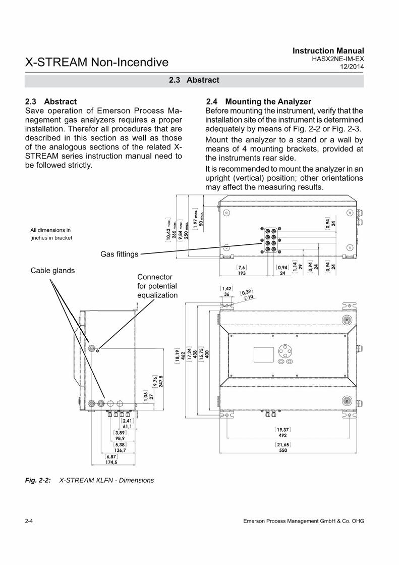
2.3 AbstractSave operation of Emerson Process Ma-nagement gas analyzers requires a proper installation. Therefor all procedures that are described in this section as well as those of the analogous sections of the related X-STREAM series instruction manual need to be followed strictly.
2.4 Mounting the AnalyzerBefore mounting the instrument, verify that the installation site of the instrument is determined adequately by means of Fig. 2-2 or Fig. 2-3.Mount the analyzer to a stand or a wall by means of 4 mounting brackets, provided at the instruments rear side.It is recommended to mount the analyzer in an upright (vertical) position; other orientations may affect the measuring results.
All dimensions in mm [inches in brackets]
Cable glands
Gas fi ttings
Connector for potentialequalization
Fig. 2-2: X-STREAM XLFN - Dimensions
2.3 Abstract

Emerson Process Management GmbH & Co. OHG 2-5
X-STREAM Non-IncendiveInstruction ManualHASX2NE-IM-EX12/2014
2In
stal
latio
n
Fig. 2-3: X-STREAM XXFN - Dimensions
All dimensions in mm [inches in brackets]
Cable glands
Connector for potentialequalization
Gas fi ttings
eqqqqqqqqqqqquuuuuuu
2.4 Installation - Mounting

Emerson Process Management GmbH & Co. OHG2-6
X-STREAM Non-IncendiveInstruction Manual
HASX2NE-IM-EX12/2014
2.5 Installation - Gas Conditioning
2.5 Gas Conditioning
In order to ensure trouble-free operation, spe-cial attention must be paid to the preparation of the gases:
All gases must be conditioned before supplying to the analyzer, to be• dry, • free of dust and • free of any aggressive com-
ponents which may damage the gas lines (e.g. by corrosi-on or solvents).
Pressure and gas fl ow must remain within the values given in the „Measurement Specifi cations“ section within this manual.If moisture cannot be avoided, it is necessary to ensure that the dew point of the gases is at least 10 °C (18 °F) below the ambient tempe-rature to avoid condensate in the gas lines.
Hints for selected gases• Calibration gases for CO and NO need
to be moistured by supplying them via a cooler.
EXPLOSION HAZARD
Consider that some gases may be harmful to explosion protection safety components, if due to an internal leak released into the enclosure!If need be take into account additional safety measures!

Emerson Process Management GmbH & Co. OHG 2-7
X-STREAM Non-IncendiveInstruction ManualHASX2NE-IM-EX12/2014
2In
stal
latio
n
2.5 Installation - Gas Conditioning
Enclosure purge optionThe purge medium (e.g. to minimize CO2 interference or for enhanced safety when measuring corrosive or poisonous gases) • must be dry, clean and free of corro-
sives or components containing sol-vents.
• has to be free of components to be measured, to minimize cross interfe-rences.
Its temperature must correspond to the am-bient temperature of the analyzer, but be at least within the range 20…35 °C (68…95 °F).Contact your Emerson Sales offi ce for infor-mation on purge gas fl ow and pressure.
We recomment to always purge the analyzer enclosure, if gases are supplied, which may harm analyzer components, if due to a leak released into the analyzer enclosure!
Open reference optionIn some cases, the measuring cell has an open reference side, to be supplied with nitrogen. This nitrogen • at least should be of quality 5.0, which
means nitrogen of purity ≥ 99.999 %.If such gas is not available, the substitute • must be dry, clean and free of corrosi-
ves or components containing solvents. • has to be free of components to be
measured, to minimize cross interfe-rences.
In any case, the gas temperature must cor-respond to the ambient temperature of the analyzer, but at least be within the range 20…35 °C (68…95 °F).Pressure and gas fl ow must remain within the values given in the „Measurement Specifi cations“ section within this manual.
Perform a calibration each time the source of this gas (e. g. bottle) has changed!

Emerson Process Management GmbH & Co. OHG2-8
X-STREAM Non-IncendiveInstruction Manual
HASX2NE-IM-EX12/2014
2.6 Installation - Gas Connections
2.6 Gas Connections
EXPLOSION HAZARD BY FLAMMABLE GASES
Take care that all external gas lines are connected as described and that they are gastight to avoid leakages! Also, gas lines for fl ammable gases must end in a safe area!Faulty connected gas lines lead to explosion hazard or even to mortal danger!
EXPLOSION HAZARD BY HARMFUL TO HEALTH GASES
Take care that all external gas lines are connected as described and that they are gastight to avoid leakages! Faulty connected gas lines lead to mortal danger!Don‘t breathe the emissions! Emissions may contain harmful to health or toxic components, and may cause headache, sickness, unconsciousness and death. Dispose emissions by a safe gas fl ue and check its function periodically!
Do not confuse gas inlets and outlets. All gases supplied must be prepared beforehand. When supplying aggressive gases, ensure that the gas lines are not damaged.Max. admissable pressure: 1500 hPa!Exhaust lines must be installed to incline downwards and be unpressurized and protected against frost, and conform to legal requirements.More information is provided in the related X-STREAM series instruction manual.

Emerson Process Management GmbH & Co. OHG 2-9
X-STREAM Non-IncendiveInstruction ManualHASX2NE-IM-EX12/2014
2In
stal
latio
n
2.6 Installation - Gas Connections
Gas connectors are accessible from the out-side, on the underside of the instrument.The number and confi guration of the gas in-lets and outlets depends on the use, the unit is to be put to, and is noted on a sticker on the underside of the instrument next to the connectors.
To simplify installation, we recommend label-ling the gas lines in accordance with these markings. This avoids confusion, should the analyzer need to be disconnected for maintenance. Should it be necessary to open the gas lines, the gas connectors should be sealed with PVC caps, to prevent pollution by moisture, dust, etc.
See fi gures 2-2 and 2-3 for an arrangement of gas in- & outlets. All connections are labeled as follows (ex-emplary):
Fig. 2-4: Labelling of Gas Connectors (example)
Gas connections
Gas connectionsmax number 8max for purging (incl. / separate) 2 incl.material PVDF; stainless steel (opt.)sizes 6/4 mm; 1⁄4"
TRACE OXYGEN MEASUREMENT
The sensor for trace oxygen measurements is a consumable. As soon as it is in contact with oxygen, the remaining lifetime counts down.For this reason, the sensor is shipped as separate unit, within a sealed bag, to avoid unintended contact with oxygen! Install the sensor considering all associated instructions short before startup of the analyzer.Do not use synthetic gas lines, as ambient oxygen may penetrate into the gas lines and infl uence the measurement!

Emerson Process Management GmbH & Co. OHG2-10
X-STREAM Non-IncendiveInstruction Manual
HASX2NE-IM-EX12/2014
2.7 Installation - Electrical
2.7 Electrical Installation
EXPLOSION AND ELECTRICAL SHOCK HAZARD
Failure to follow the instructions provided below may cause warranty invalidation, property damage and personal injury or death!Installation and connecting power and signal cables are subject to qualifi ed personnel only taking into account all applicable standards and legislative requirements!Take care of the relevant installation standards, as there are (but not limited to) e.g. EN 60079-14 (Europe), National Electrical Code (NEC-NFPA 70; USA), Canadian Electrical Code (CEC; Canada), IEC 60079-14 (International) and others, and all corresponding standards.Installation of these instruments is subject to qualifi ed personnel only, familiar with the resulting potential risks! Instruments providing screw terminals for electrical connections may require working near live part!A power switch or circuit breaker (complying with IEC 60947-1/-3) has to be provided in the building installation. This switch has to be installed near by analyzer, must be easily operator accessible and has to be assigned as disconnector for the analyzer.Disconnect instruments with screw terminals from power when working at power terminals (operate power switch / circuit breaker in building installation)!Connecting and disconnecting fl ameproof X-STREAM analyzers is permitted only, if the instrument and all associated power & signal lines are de-energized!The analyzers provide a protective earth terminal. To prevent electrical shock hazards the instruments must be connected to a protective earth. Therefore the instruments must be connected to power by using a three wire power cable with earth conductor!Any interruption of the earth connector inside or outside the instrument or disconnecting the earth terminal may cause potential electrical shock hazzard! The analyzers do not provide a power switch and are operable when connec-ted to power.

Emerson Process Management GmbH & Co. OHG 2-11
X-STREAM Non-IncendiveInstruction ManualHASX2NE-IM-EX12/2014
2In
stal
latio
n
• Connect the housing to a ground or equi-potential bonding conductor.
• Keep all cabels, entering the housing, as short as possible.
• The cable glands are intended for cables with an outer diameter of 7 to 12 mm [0.27 to 0.47 in]. Special adapters enabling to mount thinner or multiple cables in one
connection can be provided on request.• Supply terminals are intended for cab-
les with a cross section of up to 4 mm2 [11 AWG]
• Use shielded cables only for signal lines to ensure electromagnetic compatibility (EMC).
3. Feed cable through dome nut and clam-ping insert
4. Fold braided shield over clamping insert
1. Strip the cabel 2. Expose braided
shield5. Make sure that brai-
ded shield overlaps the O-ring by 3⁄32“ (2 mm)
6. Push clamping insert into body and tighten dome nut
7. Assemble into hou-sing and you´re done!
2.7 Installation - Electrical
Installing cable glands with shielded cables
All signal cables are connected to screw-type terminals located inside the housing. Access to the internal components is gained by re-leasing the two (upper enclosure´s) fasteners and opening the front panel sidewards.All cables must be fed through cable glands and secured with a gland nut.
Preparation of signal cablesSignal in- and outputs
Properly installed, the glands act as a strain relief and guarantee EMC (electromagnetic compatibility):
Emerson Process Management GmbH & Co. OHG2-12
X-STREAM Non-IncendiveInstruction Manual
HASX2NE-IM-EX12/2014
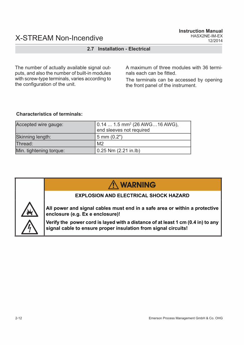
The number of actually available signal out-puts, and also the number of built-in modules with screw-type terminals, varies according to the confi guration of the unit.
A maximum of three modules with 36 termi-nals each can be fi tted. The terminals can be accessed by opening the front panel of the instrument.
2.7 Installation - Electrical
Characteristics of terminals:
Accepted wire gauge: 0.14 ... 1.5 mm2 (26 AWG…16 AWG), end sleeves not required
Skinning length: 5 mm (0.2")Thread: M2 Min. tightening torque: 0.25 Nm (2.21 in.lb)
EXPLOSION AND ELECTRICAL SHOCK HAZARD
All power and signal cables must end in a safe area or within a protective enclosure (e.g. Ex e enclosure)!Verify the power cord is layed with a distance of at least 1 cm (0.4 in) to any signal cable to ensure proper insulation from signal circuits!

Emerson Process Management GmbH & Co. OHG 2-13
X-STREAM Non-IncendiveInstruction ManualHASX2NE-IM-EX12/2014
2In
stal
latio
n
Fig. 2-5: Terminals Block X1 - Analog Signals and Relay Outputs 1-4
Note!Consider the special installation instruc-tions in chapter 4 of the X-STREAM gas analyzer series manuals and the notes on installing cable glands on page 2-8!
Analog signalsRelay outputs 1 - 4 Terminals for analog signals and relais outputs1 - 4 are located on the outer left module(terminal block X1; Fig. 2-5).
**) Confi guration of relay out-put terminals as per standard factory setting (NAMUR status signals)
PinSignal
P2.1
Channel 1, (+) 4 (0) - 20 m
AP
2.2C
hannel 1, GN
DP
2.3C
hannel 2, (+) 4 (0) - 20 mA
P2.4
Channel 2, G
ND
P2.5
Channel 3, (+) 4 (0) - 20 m
AP
2.6C
hannel 3, GN
DP
2.7C
hannel 4, (+) 4 (0) - 20 mA
P2.8
Channel 4, G
ND
P2.9
not usedP
2.10not used
P2.11
not usedP
2.12not used
P3.1
not usedP
3.2not used
P3.3
Output 1 (Failure), N
CP
3.4O
utput 1 (Failure), NO
P3.5
Output 1 (Failure), C
OM
P3.6
Output 2 (M
aintenance Request), N
CP
3.7O
utput 2 (Maintenance R
equest), NO
P3.8
Output 2 (M
aintenance Request), C
OM
P3.9
Output 3 (O
ut of Spec), N
CP
3.10O
utput 3 (Out of S
pec), NO
P3.11
Output 3 (O
ut of Spec), C
OM
P3.12
Output 4 (Function check), N
CP
4.1O
utput 4 (Function check), NO
P4.2
Output 4 (Function check), C
OM
P4.3
not usedP
4.4P
4.5P
4.6P
4.7P
4.8P
4.9P
4.10P
4.11P
4.12
Relay Outputs**) Analog OutputsSerial Interface*)
P4.3
not usedP
4.4P
4.5P
4.6P
4.7P
4.8P
4.9P
4.10P
4.11P
4.12
Serial Interface*)
P2.9
not usedP
2.10not used
P2.11
not usedP
2.12not used
P3.1
not usedP
3.2not used
2.7 Installation - Electrical
Specifi cation of analog signal outputs: 4 (0) – 20 mA; burden: RB ≤ 500 Ω
Specifi cation of relay outputs 1–4:
electrical specifi cation max. load. 30 V; 1 A; 30 W resistive
mechancialspecifi cation
Dry relay change-over contacts can be used as NO or NC
X

Emerson Process Management GmbH & Co. OHG2-14
X-STREAM Non-IncendiveInstruction Manual
HASX2NE-IM-EX12/2014
*) See table below
Serial InterfaceSpecifi cation and interface control:
Analyzer instruction manual, chapter 9The 9 terminals on the left (28 - 36) of the strip next to the power connections carry the Modbus interface signals.
Notes!Consider the special installation instruc-tions in chapter 4 of the X-STREAM gas analyzer series manuals and the notes on installing cable glands on page 2-9!
X-STREAM analyzers are classifi ed as DTE (Data Terminal Equipment).
The type of serial interface is marked on a label nearby the terminals (see sample above)
Assignment of serial interface terminals
Fig. 2-6: Terminals Block X1 - Serial Interface
2.7 Installation - Electrical
PinSignal
P2.1
Channel 1, (+) 4 (0) - 20 m
AP
2.2C
hannel 1, GN
DP
2.3C
hannel 2, (+) 4 (0) - 20 mA
P2.4
Channel 2, G
ND
P2.5
Channel 3, (+) 4 (0) - 20 m
AP
2.6C
hannel 3, GN
DP
2.7C
hannel 4, (+) 4 (0) - 20 mA
P2.8
Channel 4, G
ND
P2.9
Channel 5, (+) 4 (0) - 20 m
AP
2.10C
hannel 5, GN
DP
2.11not used
P2.12
not usedP
3.1not used
P3.2
not usedP
3.3O
utput 1 (Failure), NC
P3.4
Output 1 (Failure), N
OP
3.5O
utput 1 (Failure), CO
MP
3.6O
utput 2 (Maintenance R
equest), NC
P3.7
Output 2 (M
aintenance Request), N
OP
3.8O
utput 2 (Maintenance R
equest), CO
MP
3.9O
utput 3 (Out of S
pec), NC
P3.10
Output 3 (O
ut of Spec), N
OP
3.11O
utput 3 (Out of S
pec), CO
MP
3.12O
utput 4 (Function check), NC
P4.1
Output 4 (Function check), N
OP
4.2O
utput 4 (Function check), CO
MP
4.3not used
P4.4
P4.5
P4.6
P4.7
P4.8
P4.9
P4.10
P4.11
P4.12
Relay Outputs**) Analog OutputsSerial Interface*)
P2.11
not usedP
2.12not used
P3.1
not usedP
3.2not used
P3.3
Output 1 (Failure), N
CP
3.4O
utput 1 (Failure), NO
P3.5
Output 1 (Failure), C
OM
P3.6
Output 2 (M
aintenance Request), N
CP
3.7O
utput 2 (Maintenance R
equest), NO
P3.8
Output 2 (M
aintenance Request), C
OM
P3.9
Output 3 (O
ut of Spec), N
CP
3.10O
utput 3 (Out of S
pec), NO
P3.11
Output 3 (O
ut of Spec), C
OM
P3.12
Output 4 (Function check), N
CP
4.1O
utput 4 (Function check), NO
P4.2
Output 4 (Function check), C
OM
P4.3
not used
Relay Outputs**)
P2.1
Channel 1, (+) 4 (0) - 20 m
AP
2.2C
hannel 1, GN
DP
2.3C
hannel 2, (+) 4 (0) - 20 mA
P2.4
Channel 2, G
ND
P2.5
Channel 3, (+) 4 (0) - 20 m
AP
2.6C
hannel 3, GN
DP
2.7C
hannel 4, (+) 4 (0) - 20 mA
P2.8
Channel 4, G
ND
P2.9
Channel 5, (+) 4 (0) - 20 m
AP
2.10C
hannel 5, GN
D
Analog Outputs
X
Terminal MOD 485/2 wire
MOD 485/4 wire RS 232
P4.4 SER1 Common Common CommonP4.5 SER2 not used not used RXDP4.6 SER3 not used not used TXDP4.7 SER4 not used RXD1(+) not usedP4.8 SER5 D1(+) TXD1(+) CommonP4.9 SER6 not used not used not used
P4.10 7 not used not used not usedP4.11 8 not used RXD0(-) not usedP4.12 9 D0(-) TXD0(-) not used

Emerson Process Management GmbH & Co. OHG 2-15
X-STREAM Non-IncendiveInstruction ManualHASX2NE-IM-EX12/2014
2In
stal
latio
n
This connector is an option for X-STREAM X2 series.To install this connection, a cable must be fed through the cable entry without a connector.
The connector can be wired on when the free end has been fed into the instrument: We recommend the VARIOSUB RJ45 QUICK-ON connector (PHOENIX CONTACT), which is supplied with the unit and requires no spe-cial tools. Wiring instructions can be found in the separate manual supplied with the connector.
RJ45 Ethernet connection
Fig. 2-7: Ethernet Connector
Pin 1 Pin 8
Pin no. Signal
1 TX+2 TX-3 RX+6 RX-
other not used
2.7 Installation - Electrical

Emerson Process Management GmbH & Co. OHG2-16
X-STREAM Non-IncendiveInstruction Manual
HASX2NE-IM-EX12/2014
Consider the special installation instructions in chapter 4 of the X-STREAM gas analyzer series manuals and the notes on installing cable glands on page 2-8!
Notes!Depending on confi guration, an analyzer can be fi tted with up to two of these terminal blocks (the unit will then feature 14 digital inputs and 18 digital outputs). To aid identifi cation, the sockets are labelled X4.1 and X4.2.
PinSignal
P3.1
Output 1
P3.2
Output 2
P3.3
Output 3
P3.4
Output 4
P3.5
Output 5
P3.6
Output 6
P3.7
Output 7
P3.8
GN
D for inputs 1-7
P3.9
unusedP
3.10O
utput 5, NC
P3.11
Output 5, N
OP
3.12O
utput 5, CO
MP
4.1O
utput 6, NC
P4.2
Output 6, N
OP
4.3O
utput 6, CO
MP
4.4O
utput 7, NC
P4.5
Output 7, N
OP
4.6O
utput 7, CO
MP
4.7O
utput 8, NC
P4.8
Output 8, N
OP
4.9O
utput 8, CO
MP
4.10O
utput 9, NC
P4.11
Output 9, N
OP
4.12O
utput 9, CO
MP
2.1O
utput 10, NC
P2.2
Output 10, N
OP
2.3O
utput 10, CO
MP
2.4O
utput 11, NC
P2.5
Output 11, N
OP
2.6O
utput 11, CO
MP
2.7O
utput 12, NC
P2.8
Output 12, N
OP
2.9O
utput 12, CO
MP
2.10O
utput 13, NC
P2.11
Output 13, N
OP
2.12O
utput 13, CO
M
Digital inputsDigital outputs
P4
Note!The confi guration illustra-ted here is that of the fi rst adapter, labelled X4.1. Inputs 8-14 and outputs 14-22, if available, are on the second adapter X4.2, see label above).
Fig. 2-8: Terminals Block X4.1 and X4.2 - Digital Inputs and Outputs
2.7 Installation - Electrical
Digital in- and outputs
7 or 14 digital inputs electrical specifi cation
max. 30 V, internally limited to 2.3 mAHIGH: min. 4 V; LOW: max. 3 Vcommon GND
9 or 18 additional relay outputs
electrical specifi cation max. load. 30 V; 1 A; 30 W resistive
mechancialspecifi cation
Dry relay change-over contacts can be used as NO or NC

Emerson Process Management GmbH & Co. OHG 2-17
X-STREAM Non-IncendiveInstruction ManualHASX2NE-IM-EX12/2014
2In
stal
latio
n
2.7 Installation - Electrical
Connecting the power cord
EXPLOSION HAZARD / ELECTRICAL SHOCK HAZARD
The analyzers do not provide a power switch and are operable when connec-ted to power.A power switch or circuit breaker (complying with IEC 60947.1/-3) has to be provided in the building installation. This switch has to be installed near by the analyzer, must be easily operator accessible, and has to be assigned as disconnector for the analyzer.Disconnect instruments with screw terminals from power when working at power terminals (operate power switch/ circuit breaker in building installation)!Failure to follow may cause explosion, property damage and personal injury or death!
EXPLOSION HAZARD
The analyzers provide a protective earth terminal. To prevent electrical shock hazards the instruments must be connected to a protective earth. Therefore the instruments must be connected to power by using a three wire power cable with earth conductor!Any interruption of the earth connector inside or outside the instrument or disconnecting the earth terminal may cause potential electrical shock hazard!Failure to follow may cause explosion, property damage and personal injury or death!
ELECTRICAL SHOCK HAZARD
Verify the power supply at installation site meets the specifi cation given on the analyzer´s nameplate label, before installing the instrument!Verify power cables are disconnected and/or instrument is de-energized prior to working at the terminals!Verify the power cord is layed with a distance of at least 1 cm (0.5“) to any signal cable to ensure proper insulation from signal circuits!Failure to follow may cause personal injury or death!

Emerson Process Management GmbH & Co. OHG2-18
X-STREAM Non-IncendiveInstruction Manual
HASX2NE-IM-EX12/2014
2.7 Installation - Electrical
• Feed the power cable through the upper-most cable gland at the instrument´s right side and strip the outer insulation.
• Strip the individual wires and connect to the terminals (a label is located next to the terminals on the mains fi lter housing).
• Finally, tighten the outer dome nut to se-cure the power cable.
Fig. 2-9: Power Terminals
Live LLive L
Earth PENeutral N
Power supply cable gland
The power cord is connected to screw-type terminals located inside the housing.
Power Supply Terminals
Design, max. cross section Screw type terminals with integral fues holdersmax. 4 mm² (12 AWG)
Recommended cross section min. 1,5 mm² (15 AWG)Skinning length: 8 mm (0.315"); no need to use wire end sleevesTightening torque: min. 0.5 Nm (4.4 in.lb)
Input FusesSpecifi cation AC 230 V / T 6.3 A / 5x20 mm
EXPLOSION AND ELECTRICAL SHOCK HAZARD
All power and signal cables must end in a safe area or within a protective enclosure (e.g. Ex e enclosure)!Verify the power cord is layed with a distance of at least 1 cm (0.4 in) to any signal cable to ensure proper insulation from signal circuits!

Emerson Process Management GmbH & Co. OHG 2-19
X-STREAM Non-IncendiveInstruction ManualHASX2NE-IM-EX12/2014
2In
stal
latio
n
2.7 Installation - Electrical
When all connections are correctly made and checked, • close the front panel and secure it with
the fasteners.
2.7.1 External Equipotential Bonding Connector
The instrument provides a thread (metric M5) right beside the power cable inlet, to connect an equipotential bonding conductor.The installation has to comply with sound engineering practice (for an example see Fig. 2-10). Consider formation of contact corrosion and take measures to avoid this!
CRUSHING HAZARD
Take care of crushing hazard when closing the analyzer front door!Keep out of the closing area between enclosure cover and base!
EXPLOSION HAZARD
Before completing the electrical connection of the instrument, verify cables are inserted and connected in correct manner!Ensure the earthing conductor (protective earth; PE) is connected!

Emerson Process Management GmbH & Co. OHG2-20
X-STREAM Non-IncendiveInstruction Manual
HASX2NE-IM-EX12/2014
Fig. 2-10: Equipotential Bonding Conductor Terminal
Thread (M5) for connecting the equipotential bon-ding conductor
1 Lock washer2 Ring terminal3 Flat washer4 Lock washer5 Screw M5
13
4
2
5
Take care to use a cable for the equipotential connection with at least the same cross section as provided by the power cable!
Maximum depth of the enclosu-re thread is 6 mm!Take care to use a screw of a proper length, to ensure the ring terminal (item 2) is properly fi xed!
2.7 Installation - Electrical
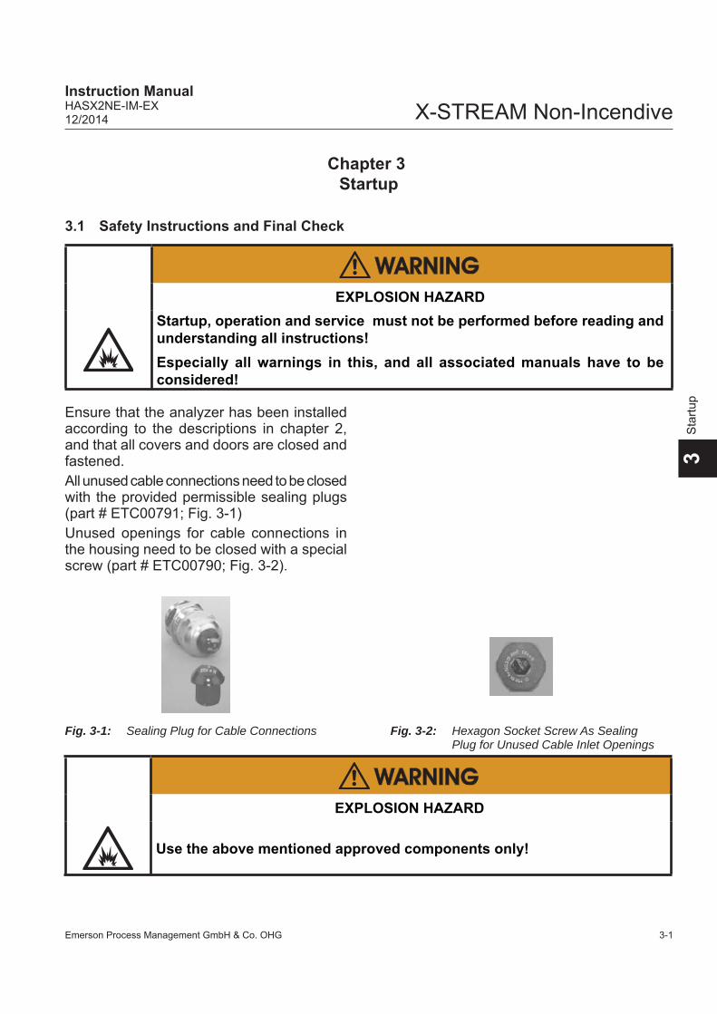
Emerson Process Management GmbH & Co. OHG 3-1
X-STREAM Non-IncendiveInstruction ManualHASX2NE-IM-EX12/2014
3S
tartu
p
Chapter 3Startup
3.1 Safety Instructions and Final Check
Ensure that the analyzer has been installed according to the descriptions in chapter 2, and that all covers and doors are closed and fastened.All unused cable connections need to be closed with the provided permissible sealing plugs(part # ETC00791; Fig. 3-1)Unused openings for cable connections in the housing need to be closed with a special screw (part # ETC00790; Fig. 3-2).
Fig. 3-1: Sealing Plug for Cable Connections Fig. 3-2: Hexagon Socket Screw As Sealing Plug for Unused Cable Inlet Openings
EXPLOSION HAZARD
Startup, operation and service must not be performed before reading and understanding all instructions!Especially all warnings in this, and all associated manuals have to be considered!
EXPLOSION HAZARD
Use the above mentioned approved components only!
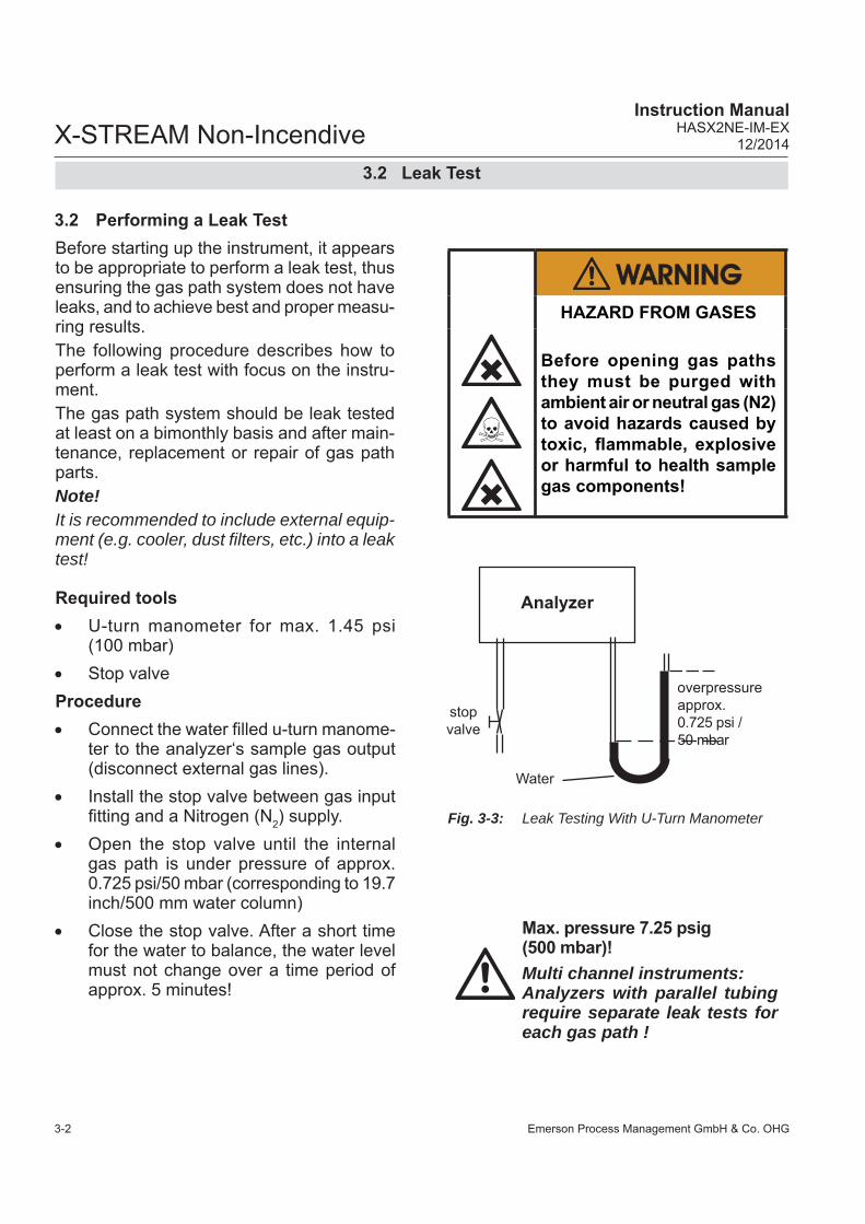
Emerson Process Management GmbH & Co. OHG3-2
X-STREAM Non-IncendiveInstruction Manual
HASX2NE-IM-EX12/2014
3.2 Leak Test
Max. pressure 7.25 psig (500 mbar)!Multi channel instruments:Analyzers with parallel tubing require separate leak tests for each gas path !
Before starting up the instrument, it appears to be appropriate to perform a leak test, thus ensuring the gas path system does not have leaks, and to achieve best and proper measu-ring results.The following procedure describes how to perform a leak test with focus on the instru-ment. The gas path system should be leak tested at least on a bimonthly basis and after main-tenance, replacement or repair of gas path parts.Note!It is recommended to include external equip-ment (e.g. cooler, dust fi lters, etc.) into a leak test!
3.2 Performing a Leak Test
Required tools U-turn manometer for max. 1.45 psi
(100 mbar) Stop valveProcedure Connect the water fi lled u-turn manome-
ter to the analyzer‘s sample gas output (disconnect external gas lines).
Install the stop valve between gas input fi tting and a Nitrogen (N2) supply.
Open the stop valve until the internal gas path is under pressure of approx. 0.725 psi/50 mbar (corresponding to 19.7 inch/500 mm water column)
Close the stop valve. After a short time for the water to balance, the water level must not change over a time period of approx. 5 minutes!
Analyzer
overpressure approx. 0.725 psi / 50 mbar
stop valve
Water
Fig. 3-3: Leak Testing With U-Turn Manometer
HAZARD FROM GASES
Before opening gas paths they must be purged with ambient air or neutral gas (N2) to avoid hazards caused by toxic, fl ammable, explosive or harmful to health sample gas components!

Emerson Process Management GmbH & Co. OHG 3-3
X-STREAM Non-IncendiveInstruction ManualHASX2NE-IM-EX12/2014
3S
tartu
p
3.3 Switching on
3.3 Switching On
OPERATION AT LOW TEMPERATURES
When operating an instrument at temperatures below 0 °C (32 °F), do NOT apply gas nor operate the internal pump before the warmup time has elapsed!Violation may result in condensation inside the gas paths or damaged pump diaphragm!Consider the instructions in the X-STREAM X2 series manual!
EXPLOSION HAZARD
Before applying power and signals:• Verify for proper installation• Verify that all covers and plugs are properly installed and in place!• Verify that all gas connections are tight.Violation may result in explosion, personal injury or death!
After all safety aspects are followed and chek-ked, the instrument may be powered .
Once the unit has been unpacked and in-stalled, we recommend to fi rst check the settings, and if necessary adjust them to the user’s needs. e.g:• What hardware is installed?• Is the unit configured to your needs
(alarms, inputs, outputs, etc.)In order for the information in this chapter to be of any relevance, the unit must have
been installed according to the instructions in chapter 2.The following pages describe how to perform a leak test, navigate through the menus and what is to be observed when confi guring the unit. For the fi rst startup after installation, follow the step-by-step instructions for navi-gating the menus, allowing you to familiarise yourself with the unit and its software, and if necessary adjust the settings to your needs.
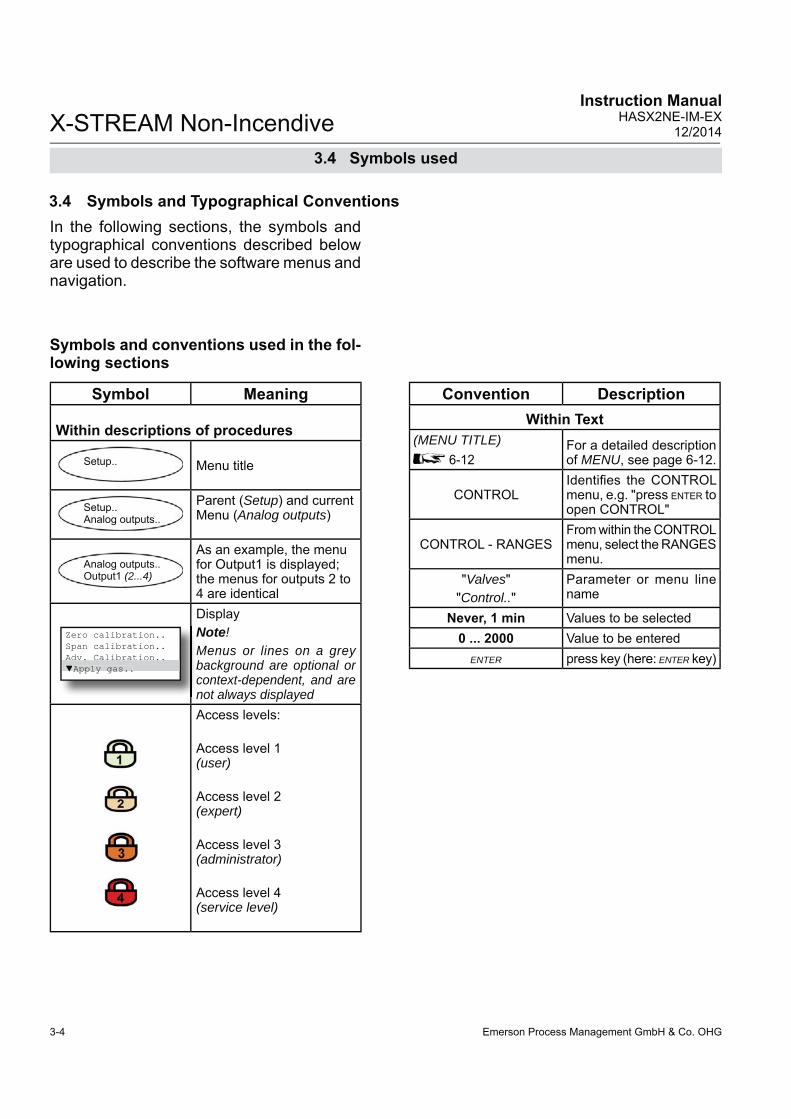
Emerson Process Management GmbH & Co. OHG3-4
X-STREAM Non-IncendiveInstruction Manual
HASX2NE-IM-EX12/2014
3.4 Symbols used
Symbols and conventions used in the fol-lowing sections
Symbol Meaning
Within descriptions of procedures
Setup.. Menu title
Setup..Analog outputs..
Parent (Setup) and current Menu (Analog outputs)
Analog outputs..Output1 (2...4)
As an example, the menu for Output1 is displayed; the menus for outputs 2 to 4 are identical
Zero calibration..Span calibration..Adv. Calibration..Apply gas..
DisplayNote!Menus or lines on a grey background are optional or context-dependent, and are not always displayedAccess levels:
Access level 1(user)
Access level 2 (expert)
Access level 3 (administrator)
Access level 4 (service level)
Adv. Calibration..Apply gas..
In the following sections, the symbols and typographical conventions described below are used to describe the software menus and navigation.
3.4 Symbols and Typographical Conventions
Convention DescriptionWithin Text
(MENU TITLE) 6-12
For a detailed description of MENU, see page 6-12.
CONTROLIdentifi es the CONTROL menu, e.g. "press ENTER to open CONTROL"
CONTROL - RANGESFrom within the CONTROL menu, select the RANGES menu.
"Valves""Control.."
Parameter or menu line name
Never, 1 min Values to be selected 0 ... 2000 Value to be entered
ENTER press key (here: ENTER key)
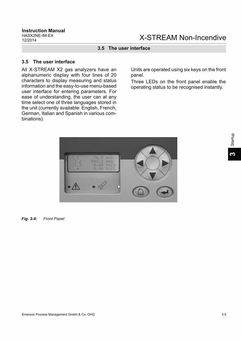
Emerson Process Management GmbH & Co. OHG 3-5
X-STREAM Non-IncendiveInstruction ManualHASX2NE-IM-EX12/2014
3S
tartu
p
3.5 The user interface
All X-STREAM X2 gas analyzers have an alphanumeric display with four lines of 20 characters to display measuring and status information and the easy-to-use menu-based user interface for entering parameters. For ease of understanding, the user can at any time select one of three languages stored in the unit (currently available: English, French, German, Italian and Spanish in various com-binations).
Fig. 3-4: Front Panel
3.5 The user interfaceUnits are operated using six keys on the front panel.Three LEDs on the front panel enable the operating status to be recognised instantly.

Emerson Process Management GmbH & Co. OHG3-6
X-STREAM Non-IncendiveInstruction Manual
HASX2NE-IM-EX12/2014
3.5.1 Display
The display has 4x20 characters, either liquid crystal or vacuum fl uorescent (LCD or VFD).What information is displayed depends on the currently displayed menu.
3.5.2 Status LED
3.5 The user interface
Three status LED indicate the unit’s status, recognisable from a distance. Status is indicated in accordance with the German NAMUR NE 44 recommendations.
“Failure” is indicated when this red LED is lit.
A fl ashing red LED in the middle indicates “Maintenance request”, “Function check” or “Off-spec operation”.
The third, green LED indicates the power supply status:on: power supply OKoff: power supply interrupted
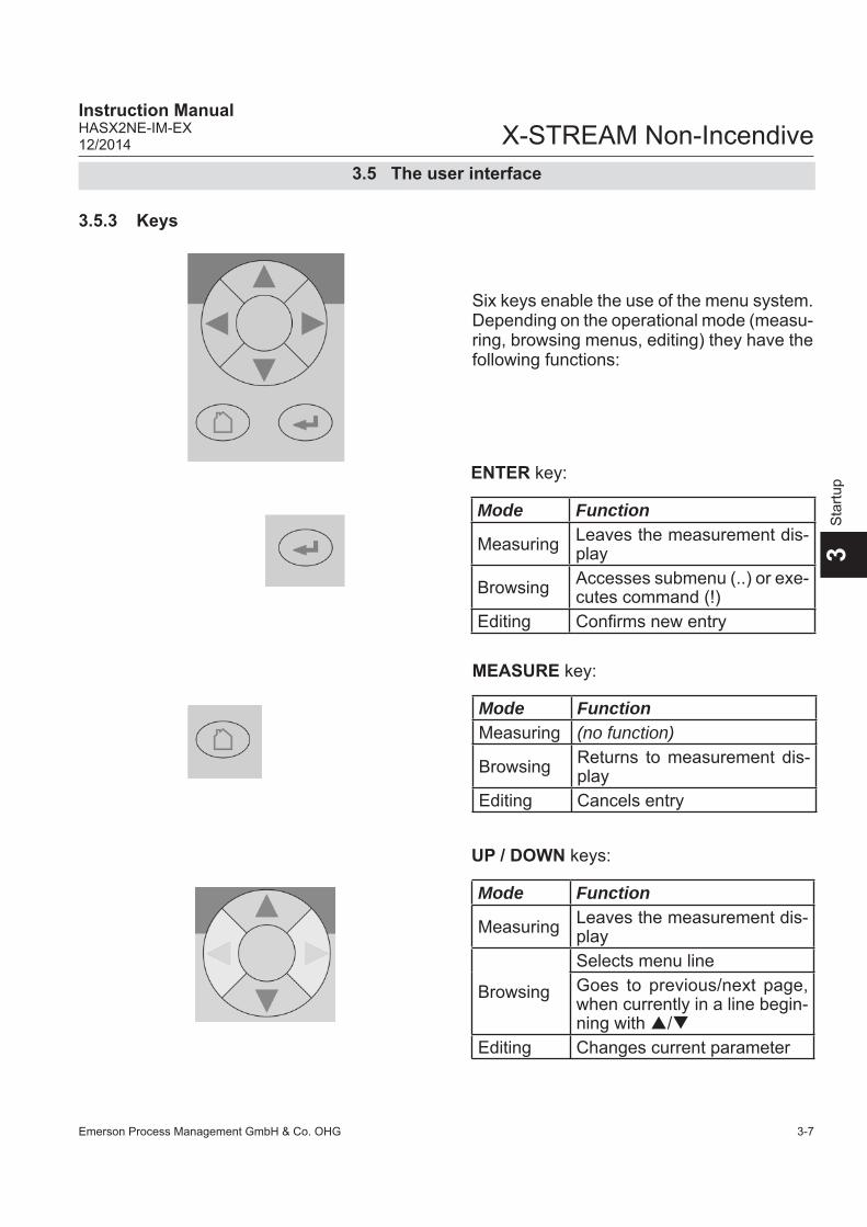
Emerson Process Management GmbH & Co. OHG 3-7
X-STREAM Non-IncendiveInstruction ManualHASX2NE-IM-EX12/2014
3S
tartu
p
3.5.3 Keys
Six keys enable the use of the menu system. Depending on the operational mode (measu-ring, browsing menus, editing) they have the following functions:
ENTER key:
Mode Function
Measuring Leaves the measurement dis-play
Browsing Accesses submenu (..) or exe-cutes command (!)
Editing Confi rms new entry
MEASURE key:
Mode FunctionMeasuring (no function)
Browsing Returns to measurement dis-play
Editing Cancels entry
UP / DOWN keys:
Mode Function
Measuring Leaves the measurement dis-play
Browsing
Selects menu lineGoes to previous/next page, when currently in a line begin-ning with /
Editing Changes current parameter
3.5 The user interface

Emerson Process Management GmbH & Co. OHG3-8
X-STREAM Non-IncendiveInstruction Manual
HASX2NE-IM-EX12/2014
LEFT key:
Mode Function
Measuring Leaves the measurement display
Browsing Goes up 1 level or page in menu system
Editing
Moves cursor 1 space Leaves channel selectionCancels editing of given pa-rameterGoes to previous page, when showing in fi rst line
RIGHT key:
Mode FunctionMeasuring Leaves the measurement
displayBrowsing Accesses submenu (..)
EditingGoes to next page, when showing in fourth lineMoves cursor 1 space
3.5 The user interface
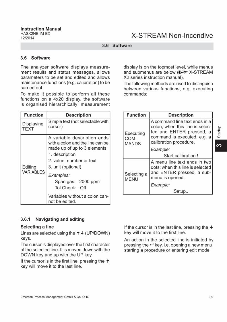
Emerson Process Management GmbH & Co. OHG 3-9
X-STREAM Non-IncendiveInstruction ManualHASX2NE-IM-EX12/2014
3S
tartu
p
3.6 Software
The analyzer software displays measure-ment results and status messages, allows parameters to be set and edited and allows maintenance functions (e.g. calibration) to be carried out. To make it possible to perform all these functions on a 4x20 display, the software is organised hierarchically: measurement
3.6 Software
display is on the topmost level, while menus and submenus are below ( X-STREAM X2 series instruction manual).The following methods are used to distinguish between various functions, e.g. executing commands:
3.6.1 Navigating and editingSelecting a line Lines are selected using the (UP/DOWN) keys. The cursor is displayed over the fi rst character of the selected line. It is moved down with the DOWN key and up with the UP key. If the cursor is in the fi rst line, pressing the key will move it to the last line.
If the cursor is in the last line, pressing the key will move it to the fi rst line.An action in the selected line is initiated by pressing the key, i.e. opening a new menu, starting a procedure or entering edit mode.
Function Description
Displaying TEXT
Simple text (not selectable with cursor)
EditingVARIABLES
A variable description ends with a colon and the line can be made up of up to 3 elements:1. description2. value: number or text3. unit (optional)
Examples: Span gas: 2000 ppmTol.Check: Off
Variables without a colon can-not be edited.
Function Description
Executing COM-MANDS
A command line text ends in a colon; when this line is selec-ted and ENTER pressed, a command is executed, e.g. a calibration procedure.Example:
Start calibration !
Selecting a MENU
A menu line text ends in two dots; when this line is selected and ENTER pressed, a sub-menu is opened.Example:
Setup..
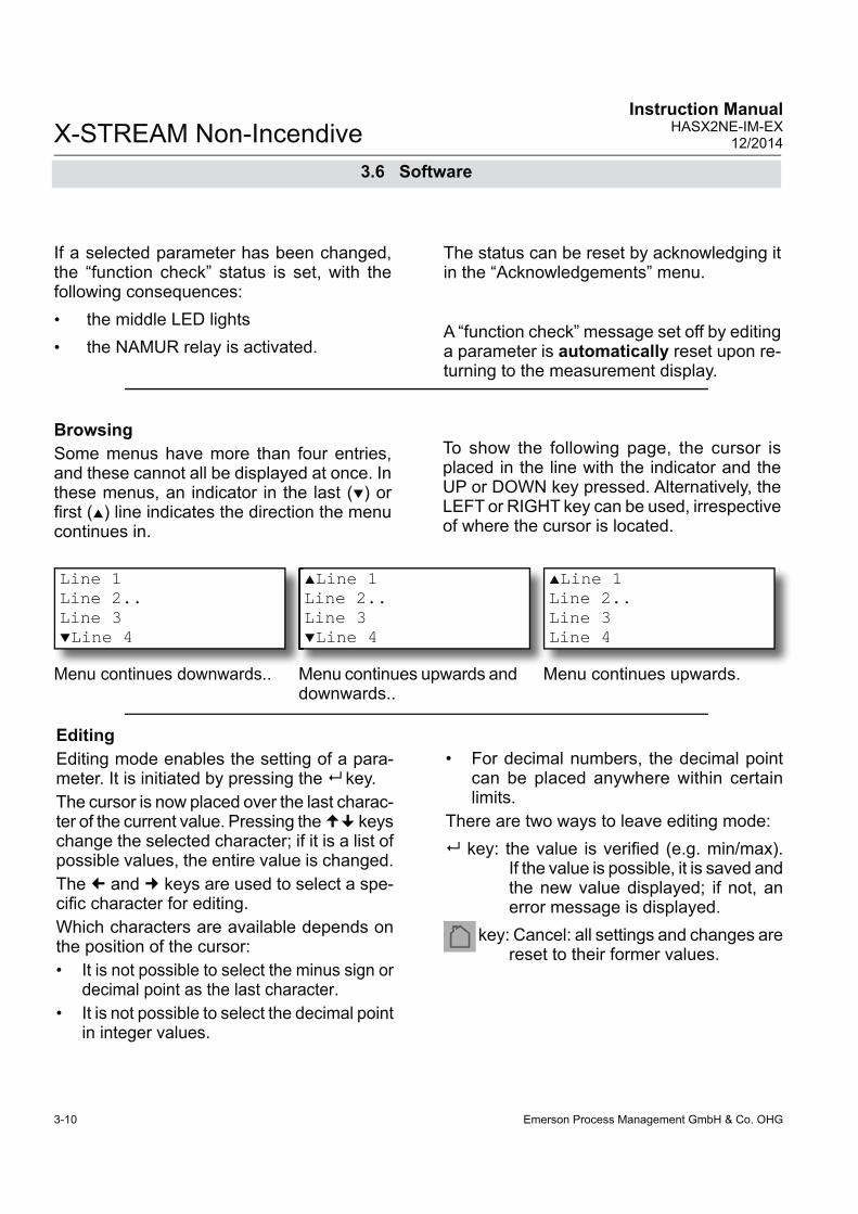
Emerson Process Management GmbH & Co. OHG3-10
X-STREAM Non-IncendiveInstruction Manual
HASX2NE-IM-EX12/2014
EditingEditing mode enables the setting of a para-meter. It is initiated by pressing the key. The cursor is now placed over the last charac-ter of the current value. Pressing the keys change the selected character; if it is a list of possible values, the entire value is changed. The and keys are used to select a spe-cifi c character for editing.Which characters are available depends on the position of the cursor: • It is not possible to select the minus sign or
decimal point as the last character. • It is not possible to select the decimal point
in integer values.
• For decimal numbers, the decimal point can be placed anywhere within certain limits.
There are two ways to leave editing mode: key: the value is verifi ed (e.g. min/max).
If the value is possible, it is saved and the new value displayed; if not, an error message is displayed.
key: Cancel: all settings and changes are reset to their former values.
BrowsingSome menus have more than four entries, and these cannot all be displayed at once. In these menus, an indicator in the last () or fi rst () line indicates the direction the menu continues in.
To show the following page, the cursor is placed in the line with the indicator and the UP or DOWN key pressed. Alternatively, the LEFT or RIGHT key can be used, irrespective of where the cursor is located.
Line 1 Line 2..Line 3Line 4
Menu continues upwards and downwards..
Line 1 Line 2..Line 3Line 4
Menu continues downwards..
Line 1 Line 2..Line 3Line 4
Menu continues upwards.
If a selected parameter has been changed, the “function check” status is set, with the following consequences:• the middle LED lights• the NAMUR relay is activated.
The status can be reset by acknowledging it in the “Acknowledgements” menu.
A “function check” message set off by editing a parameter is automatically reset upon re-turning to the measurement display.
3.6 Software

Emerson Process Management GmbH & Co. OHG 3-11
X-STREAM Non-IncendiveInstruction ManualHASX2NE-IM-EX12/2014
3S
tartu
p
3.6.2 Access levelsAccess levels can be used to prevent changes to parameters by unauthorised personnel. The X-STREAM menu system supports four prioritized access levels which can be acti-vated and deactivated separately, and should be supplied with their own access codes.
Level four has the highest priority and is used for factory settings — only qualifi ed EMERSON service personnel have access to this level.
Level three allows access to system admin parameters, e.g. for data capture and proces-sing systems.
Level two covers the expert settings, e.g. basic settings for calibration.
Level one is the user level and includes parameters which should be set by trained personnel.
Any menus not assigned to one of these le-vels are not editable or are of minor relevance.In this chapter, the descriptions of the indi-vidual menus also indicate which level the
menus are in. These assignments cannot be changed. Access codes for levels 1 to 3 can be defi -ned, activated and deactivated by the client. The analyzer is delivered with the following settings:Level Access code Status 1 00000001 Off 2 00000002 Off 3 00000003 Off
It is recommended to set new access codes if they are to be activated.
Note!If a lower level is locked (i.e. its code acti-vated), all higher levels will also be locked.If a higher level is unlocked (i.e. its code deactivated), all lower levels will also be au-tomatically unlocked.
Component selection menuA single channel analyzer has only one measurement channel (component): editing any parameter will only effect this one chan-nel.A multi-channel analyzer requires that a channel must be selected before its parame-ters can be changed. When this selection is necessary, a menu is automatically displayed; it is not displayed on single-channel units.
Select component
Component: CO2.1 Back -
3.6 Software

Emerson Process Management GmbH & Co. OHG3-12
X-STREAM Non-IncendiveInstruction Manual
HASX2NE-IM-EX12/2014
3.6.3 Special messagesDepending on the last action performed by the user, one of the following messages may be displayed to assist or inform the user (the two confi rmation messages are displayed only for a few seconds):
Confi rmation of cancellation:Confi rms that a procedure (e.g. calibration) has been aborted.
(i)
CANCELLED
Confi rmation of execution of command:Confi rms that a procedure (e.g. calibration) has been started.
3.6 Software
Access Code 1
Code 00000001 Back - Press
Entering access codesIf an access code is required for a menu, the following message is displayed:
Information on incorrect entry:The value entered by the user is outside valid limits. The display indicates what limits apply.Pressing returns the display to the previous screen to allow a valid setting to be entered.
Wrong InputMin: 500Max: 10.000 Press
Use• the UP/DOWN keys to change the cur-
rently selected digit, • the LEFT/RIGHT keys to select a different
digit,• the ENTER key to submit the codeor• the MEASURE key to leave edit mode
and return to the previous display.
(i)
-COMMAND EXECUTED-

Emerson Process Management GmbH & Co. OHG 3-13
X-STREAM Non-IncendiveInstruction ManualHASX2NE-IM-EX12/2014
3S
tartu
p
3.7 Powering up
When the unit is powered up, a series of in-ternal tests is automatically performed. During this time the front panel keys are disabled,
The measurement display is shown • automaticaly on completion of the boot
sequence• when the MEASURE key is pressed• automatically after a set period of time
of inactivity (i.e. with no keys being pressed).
The information displayed in the four lines of the measurement display can be determined by the operator:• Sample gas components, measuring
results and measuring units for each channel
• additional measurements, e.g. pressu-re, gas fl ow, temperature
• nothing (empty line)The factory settings are as follows:
Line 1: measured value of channel 1Line 2: measured value of channel 2Line 3: measured value of channel 3Line 4: measured value of channel 4
Note!
If less than four channels are installed in the
unit, only the values of the available channels will be shown.Line 4 is also used to display plain text status information (errors, maintenance requests, function checks or off-spec performance).If such messages are active, line 4 alternates between the messages and the parameter selected for line 4.Active messages are stored in an internal buffer. If there is more than one message in the buffer, the display will cycle through them.Each message is not just shown in the display as text, but also indicated by the appropriate LED on the front panel and the activation of the appropriate NAMUR relay (if a relay has been assigned to that NAMUR function; X-STREAM X2 series instruction manual).Note!There are also functions, that do activate a relay or LED, but are not shown on the display (e.g. concentration alarms). In such cases, check the status menu for more information.
CO2.1 135.1 ppmO2.2 201952 ppmCO.3 58.8 ppmH2.4 1.5 %
MEASUREMENT DISPLAY
3.7 Powering up
3.7.1 Boot sequencewhile the time remaining for the boot se-quence counts down in the display.
3.7.2 Measurement display
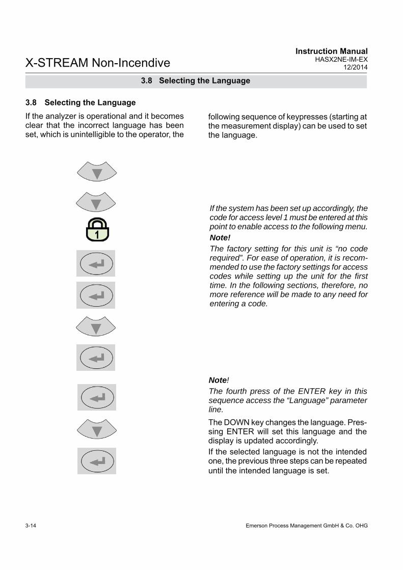
Emerson Process Management GmbH & Co. OHG3-14
X-STREAM Non-IncendiveInstruction Manual
HASX2NE-IM-EX12/2014
If the analyzer is operational and it becomes clear that the incorrect language has been set, which is unintelligible to the operator, the
3.8 Selecting the Language
The DOWN key changes the language. Pres-sing ENTER will set this language and the display is updated accordingly.If the selected language is not the intended one, the previous three steps can be repeated until the intended language is set.
Note!The fourth press of the ENTER key in this sequence access the “Language” parameter line.
3.8 Selecting the Language
following sequence of keypresses (starting at the measurement display) can be used to set the language.
If the system has been set up accordingly, the code for access level 1 must be entered at this point to enable access to the following menu. Note!The factory setting for this unit is “no code required”. For ease of operation, it is recom-mended to use the factory settings for access codes while setting up the unit for the fi rst time. In the following sections, therefore, no more reference will be made to any need for entering a code.

Emerson Process Management GmbH & Co. OHG 3-15
X-STREAM Non-IncendiveInstruction ManualHASX2NE-IM-EX12/2014
3S
tartu
p
3.9 Checking the settings
Language..
Setup..
Display..
Starting with the measurement display, pres-sing any key except the MEASURE key will ac-cess the MAIN MENU; from here, the following steps are to be followed: (If the display is showing anything other than the measurement display, pressing the MEASURE key will return to the measurement display).
3.9 Checking the settings
Set the preferred language for the software; each analyzer shipped with 3 out of below list of available languages.Currently available (may be extended by future software versions.): EN: English, FR: French, DE: German,IT: Italian, ES: Spanish, PT: Portuguese
Note!If you are unfamiliar with the language set:
page 3-13 shows the sequence to be used to set a different language.
( )
Language
Language: EN
If the system has been set up accordingly, the code for access level 1 must be entered at this point to enable access to the following menu. Note!The factory setting for this unit is “no code required”. For ease of operation, it is recom-mended to use the factory settings for access codes while setting up the unit for the fi rst time. In the following sections, therefore, no more reference will be made to any need for entering a code.
The following sections are structured so that the user can work through them one by one after powering up the unit. After completing
these steps, the unit will be confi gured to the user’s needs and functioning correctly.

Emerson Process Management GmbH & Co. OHG3-16
X-STREAM Non-IncendiveInstruction Manual
HASX2NE-IM-EX12/2014
3.9 Checking the settings
The cursor is now in the “In/Outputs” line over an arrowhead. Press the DOWN key to display the next menu page and open the INSTALLED OPTIONS submenu.
InstalledOptions..Communication..Alarms..Save-Load..
Press the LEFT key several times to return to the SETUP menu.
This menu is in two columns and indicates which of the possible optional components are installed in the unit. The values displayed on your unit may differ from those illustrated here.
Do not edit any entries in these menus without special know-ledge.Incorrect entries may result in incorrect results or impair the performance of the unit.This initial access to this menu is intended to gain information on the confi guration of the unit.
3.9.1 Installed options
All X-STREAM gas analyzers can be fi tted with a variety of optional components: follow these steps to see which options are installed on your analyzer.
Valves: Internal COM-Interf: Yes Pump: YesFlow monitor: Yes
Page 1
Page 22
DigitalIO: 1Pressure: InternalAnalog outputs 4More..
Protocol: MODB RTUMODB Mode: 32BitID number: 2Interface: RS485/2w
Baud rate: 19200Parity: No
In the two pages of the COMMUNICATION menu, you can verify the parameters of the serial interface, and if necessary select the protocol to be used for data transfer.
Press the LEFT key twice to return to the SETUP menu.

Emerson Process Management GmbH & Co. OHG 3-17
X-STREAM Non-IncendiveInstruction ManualHASX2NE-IM-EX12/2014
3S
tartu
p
3.9 Checking the settings
Check the settings for the measurement dis-play, temperature and pressure units, and for menu access: use the DOWN and ETER keys to access the submenus.
If a setting is not in accordance with your requirements, access that menu ad adjust the parameter.
Press the LEFT key to return to the display setup menu.
3.9.2 Confi guring the display
Line 1: Comp-1Line 2: Comp-2Line 3: Comp-3Line 4: Comp-4
Page 2
Select the value to be displayed in each line of the measurement display. The following options are available: Comp-1 ... Comp-4, Temp-1 ... Temp-4, Press-1 ... Press-4, Flow-1 ... Flow-4 Blank (nothing)Note!X-STREAM currently supports only one pres-sure sensor. Values Press-1 to Press-4 thus refer to the same sensor .
Setup..Display..
Component..Temperature..Pressure..Gasfl ow..
Page 3
The measurement units for the displayed values can be changed in the submenus on page 3.
For example, here are the options for the display of temperature values:
TemperatureUnit: °CDecimalPlaces: 1Temp-1 63.7 °C
Current temperature; here: sensor 1.
Set temperature unitOptions available: °C, °F
Set number of decimal places for temperature display: 0 to 4

Emerson Process Management GmbH & Co. OHG3-18
X-STREAM Non-IncendiveInstruction Manual
HASX2NE-IM-EX12/2014
Multi-channel unit:Select the component to be set in the gas component selection menu.
Once the display settings have been checked, press the LEFT key to return to the SETUP menu, then open the CALIBRATION menu where e.g. the calibration gas concentrations can be entered..
Calibration..Calibration gases..
In the CALIBRATION GASES menu, the values for zero and span gas should be en-tered: these values should be taken from the gas supplier’s certifi cation. Values must be correctly set for results to be accurate. In multi-channel units, the values for each channel must be entered separately.
Calibration gases
ZeroGas: 0.0 ppmSpanGas: 500.0 ppm
3.9.3 Calibration setup
3.9 Checking the settings
Press the LEFT key to return to the CALI-BRATION menu, and check the entry for “Tol.Check”.The “Tol.Check” (tolerance check) option is set to inactive (Off) by default. When the tolerance check is active (10 %), the analyzer checks during calibration whether the values set for zero and span gas conform to the concentration of the gas currently being supplied. If the concentration varies by more than 10% of the range from the value set, the calibration is aborted.
Note!For more detailed information about the cali-bration procedure, see Chapter 4.

Emerson Process Management GmbH & Co. OHG 3-19
X-STREAM Non-IncendiveInstruction ManualHASX2NE-IM-EX12/2014
3S
tartu
p
3.9 Checking the settings
This prevents calibration from being perfor-med when the incorrect gas is supplied (e.g. span gas calibration using zero gas), which would result in an incorrectly confi gured unit.
"Hold on Cal": Specifi es behaviour of analog outputs and concentration limits alarms during calibrations (follow measured value or not)..
“ Purge time”: When gas fl ow is controlled by internal or external valves, these allow the appropriate calibration gas to fl ow into the unit as soon as the calibration procedure is started. Due to the limited gas fl ow and the distance between valves and measuring cell, some time is required before the measuring cell is fi lled with the calibration gas: this is the purge time, which is to be entered here. If the calibration is started earlier, the gas lines will still contain other components and the calibration will be inaccurate.
" Valve assignment": This line is to assign internal and/or external valves the function of either zero or span gas valve. Instruments with internal valves are already factory setup.
If any of these parameters need to be changed, X-STREAM X2 instruction manual for more information.
Note!The line “Purge time” and the second menu page are only displayed if the “Valves” para-meter in the INSTALLED OPTIONS menu is not set to none.
Calibration gases..Tol.Check: AusHold on Cal: YesPurge time: 12 sPurge time: 12 s
Page 1
Valve assignment..Interval time..
Page 2
Valve assignment..Interval time..
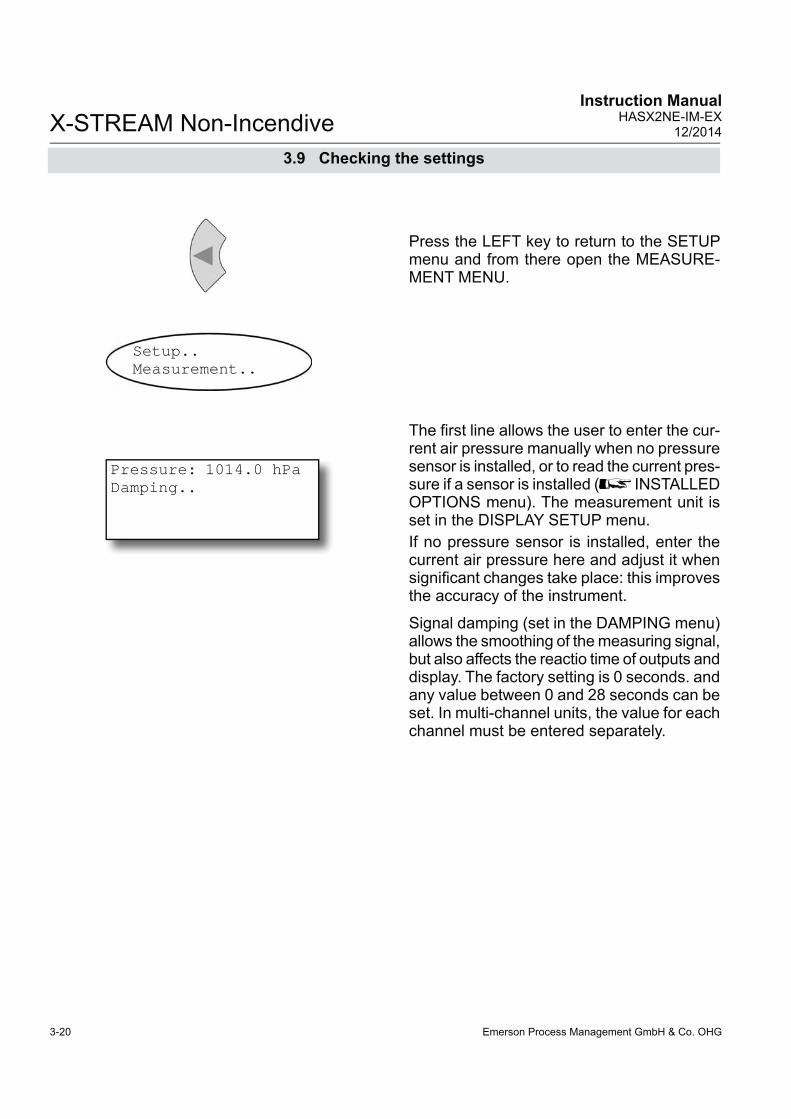
Emerson Process Management GmbH & Co. OHG3-20
X-STREAM Non-IncendiveInstruction Manual
HASX2NE-IM-EX12/2014
The fi rst line allows the user to enter the cur-rent air pressure manually when no pressure sensor is installed, or to read the current pres-sure if a sensor is installed ( INSTALLED OPTIONS menu). The measurement unit is set in the DISPLAY SETUP menu.If no pressure sensor is installed, enter the current air pressure here and adjust it when signifi cant changes take place: this improves the accuracy of the instrument.
Signal damping (set in the DAMPING menu) allows the smoothing of the measuring signal, but also affects the reactio time of outputs and display. The factory setting is 0 seconds. and any value between 0 and 28 seconds can be set. In multi-channel units, the value for each channel must be entered separately.
Pressure: 1014.0 hPaDamping..
Press the LEFT key to return to the SETUP menu and from there open the MEASURE-MENT MENU.
Setup..Measurement..
3.9 Checking the settings

Emerson Process Management GmbH & Co. OHG 3-21
X-STREAM Non-IncendiveInstruction ManualHASX2NE-IM-EX12/2014
3S
tartu
p
3.9 Checking the settings
Press the LEFT key to return to the SETUP menu, and then open the IN/OUTPUTS menu. and from there the ANALOG OUTPUTS menu.
3.9.4 Setting the analog outputs
Analog outputs
SignalRange: 0-20mAHold on cal: Yes
Setup..In/Outputs..Analog outputs..
Page 1
Page 1 shows settings which are relevant for all available analog outputs: The “ SignalRange” parameter sets the signal range for the analog outputs. This entry also allows the analog outputs to be set according to the NAMUR NE43 recommendations:The 0-20 mA operational mode generates a 20 mA signal when the concentration is measured at the upper limit of the signal range. A 0 mA signal is generated when the sample gas concentration is at 0 (dead zero).However, a severed cable would also result in a signal of 0, and so an external data capture system would not be able to recognise such a failure, instead registering a gas concen-tration of 0. The usual method to detect a severed cable is to use an offset current: when the concen-tration reaches the lower limit of the range, an analog signal of 4 mA is sent. This allows the detection of a severed cable.This (life zero) mode is activated by setting the “ SignalRange” parameter to 4-20 mA.

Emerson Process Management GmbH & Co. OHG3-22
X-STREAM Non-IncendiveInstruction Manual
HASX2NE-IM-EX12/2014
3.9 Checking the settings
Operational modes conforming to NAMUR 43 recommendations ( NE 43)The modes described so far do not generate any signal which would allow the detection of a failure in the measurement system. In such a case, the behaviour of the output signal is undefi ned: either the last value is held, or a random value is sent. System failures cannot then be detected by an external data capture system.
NE43 includes recommendations for such cases, but also for the confi guration of analog outputs to detect other measurement states. X-STREAM analyzers incorporate these re-commendations as follows:Setting the “SignalRange” parameter to a value other than 0-20 mA or 4-20 mA defi -nes specifi c analog output signal levels for
system failures. Since these values are not sent during normal operation, a data capture system is able to distinguish between the following situations:• valid measured value (signal within range as per Table 5-1) • signal out of range (signal slowly rises or
falls towards the limits given in table 5-1, and holds that value until the concentration returns to within the measuring range).
• failure (signal out of range as per table 5-1, but not 0) • severed cable (no signal (0 mA)),
Table 3-1 shows an overview of all available operational modes.
Tab. 3-1: Analog Output Signals: Settings and Operational Modes
Output signal, if
"Signal-Range“
Operation ModeFailure
Signal Level acc. NE 43
Measured value is
valid
Measured value is below lower range
limit
Measured value is above upper range
limit
An internal failure
occured
Cable is broken
0-20 mA Dead-Zero - 0 ... 20 mA < -19 mA > 21.7 mA undefi ned 0 mA
4-20 mA Live-Zero - 4 ... 20 mA < -19 mA > 21.7 mA undefi ned 0 mA
0-20 mAL similar Dead-Zero below 0 ... 20 mA -0.2 mA*
(-1.8 … -0.01 mA)**20.5 mA*
(20.01 ... 21.5 mA)** -2 mA 0 mA
4-20 mAL similar Live-Zero below 4 ... 20 mA 3.8 mA* (2.2 ...3.9 mA)**
20.5 mA*(20.01 ... 21.5 mA)** 2 mA 0 mA
0-20 mAH similar Dead-Zero above 0 ... 20 mA -0.2 mA*
(-1.8 … -0.01 mA)**20.5 mA*
(20.01 ... 21.5 mA)** > 21.7 mA 0 mA
4-20 mAH similar Live-Zero above 4 ... 20 mA 3.8 mA* (2.2 ...3.9 mA)**
20.5 mA*(20.01 ... 21.5 mA)** > 21.7 mA 0 mA
Note!The application of values marked * or ** depends on the setting of "SignalRange" ( Analog outputs menu, page 6-31).
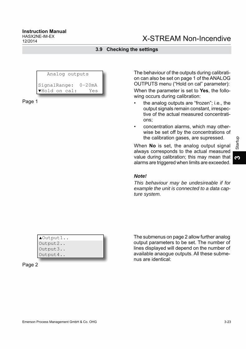
Emerson Process Management GmbH & Co. OHG 3-23
X-STREAM Non-IncendiveInstruction ManualHASX2NE-IM-EX12/2014
3S
tartu
p
3.9 Checking the settings
Analog outputs
SignalRange: 0-20mAHold on cal: Yes
Page 1
The behaviour of the outputs during calibrati-on can also be set on page 1 of the ANALOG OUTPUTS menu (“Hold on cal” parameter): When the parameter is set to Yes, the follo-wing occurs during calibration:• the analog outputs are “frozen”; i.e., the
output signals remain constant, irrespec-tive of the actual measured concentrati-ons;
• concentration alarms, which may other-wise be set off by the concentrations of the calibration gases, are supressed.
When No is set, the analog output signal always corresponds to the actual measured value during calibration; this may mean that alarms are triggered when limits are exceeded.
Note!This behaviour may be undesireable if for example the unit is connected to a data cap-ture system.
The submenus on page 2 allow further analog output parameters to be set. The number of lines displayed will depend on the number of available anaogue outputs. All these subme-nus are identical:
Page 22
Output1..Output2..Output3..Output4..
Output2..Output3..Output4..

Emerson Process Management GmbH & Co. OHG3-24
X-STREAM Non-IncendiveInstruction Manual
HASX2NE-IM-EX12/2014
Signal: Comp-1LowScale: 0 ppmHighScale: 1000 ppmZoom..
g ppZoom..
The “ Signal” parameter defi nes the value to be sent to the selected output. The following options (partly dependent on the number of measuring channels and sensors installed) are available:
Value DescriptionNone The analog signal is deactivated
0/4 mA
Either a 0 mA or 4 mA signal is generated, for example to be used to test the processing in a subsequent system. The actual type of generated signal is setup in the previous menu in the “Si-gnalRange” line ( previous page).
20 mA A 20 mA signal is generated, with which, for exa-mple, the processing of a signal can be tested.
Comp-1, Comp-2, Comp-3, Comp-4 Gas component of channel 1 to 4Temp-1, Temp-2, Temp-3, Temp-4 Measured value from temperature sensorPress-1, Press-2, Press-3, Press-4 Measured value from pressure sensor
Flow-1, Flow-2, Flow-3, Flow-4 Measured value from fl ow sensor
Zoom-C1, Zoom-C2, Zoom-C3, Zoom-C4
A “zoomed” signal is sent from the selected measuring channel (C1 to C4). If one of these op-tions is selected, the “Zoom..” line appears in the menu (see above), which allows a zoom to be set.
3.9 Checking the settings

Emerson Process Management GmbH & Co. OHG 3-25
X-STREAM Non-IncendiveInstruction ManualHASX2NE-IM-EX12/2014
3S
tartu
p
The last line on this menu allows the zoom function of the analog output to be set when that output has been assigned the Zoom signal.This function allows a part of the signal range, specifi ed by “LowScale” and “HighScale”, to be “magnifi ed” on the analog output. Unlike the scaling function, here the output is swit-ched automatically, the moment the switching point concentration is reached.
The “ LowScale” and “HighScale” parame-ters allow a concentration value to be set to correspond to the lower (0 or 4 mA) or upper signal value (20 mA). The limits for these parameters are given by the "MinRange" and "MaxRange" parameters, specifying the phy-sical measuring ranges of each instrument.Concentrations outside the range defi ned by "LowScale" and "HighScale" are not suppor-ted by an analog output.Note!Scaling may affect the analog outputs accuracy! Carefully read the information, given on (page 3-27 before scaling analog outputs!
Signal: Comp-1LowScale: 0 ppmHighScale: 1000 ppmZoom..
g ppZoom..
3.9 Checking the settings
Out
put s
igna
l
MaxRangeLowScale= 0 HighScale
<>MaxRange
scale
d ou
tput
default output
HighScale=
MaxRangeLowScale
<> 0
0
Out
put s
igna
l
scale
d ou
tput
default output
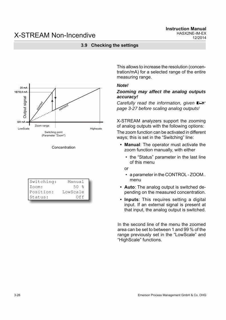
Emerson Process Management GmbH & Co. OHG3-26
X-STREAM Non-IncendiveInstruction Manual
HASX2NE-IM-EX12/2014
3.9 Checking the settings
Switching: ManualZoom: 50 %Position: LowScaleStatus: Off
This allows to increase the resolution (concen-tration/mA) for a selected range of the entire measuring range.
Note! Zooming may affect the analog outputs accuracy! Carefully read the information, given page 3-27 before scaling analog outputs!
X-STREAM analyzers support the zooming of analog outputs with the following options:The zoom function can be activated in different ways; this is set in the “Switching” line:
• Manual: The operator must activate the zoom function manually, with either • the “Status” parameter in the last line
of this menuor • a parameter in the CONTROL - ZOOM..
menu • Auto: The analog output is switched de-
pending on the measured concentration.• Inputs: This requires setting a digital
input. If an external signal is present at that input, the analog output is switched.
In the second line of the menu the zoomed area can be set to between 1 and 99 % of the range previously set in the “LowScale” and “HighScale” functions.
Out
put s
igna
l
Concentration
Switching point (Parameter "Zoom")
Zoom rangeHighscaleLowScale
standard
zoom
ed

Emerson Process Management GmbH & Co. OHG 3-27
X-STREAM Non-IncendiveInstruction ManualHASX2NE-IM-EX12/2014
3S
tartu
p
3.9 Checking the settings
Additionally, the “Position” parameter allows the X-STREAM analyzer to zoom either the lower or the higher end of the range.
Position: LowScale
Out
put s
igna
l
Concentration
Concentration
Switch point (“Zoom” parameter applied
from LowScale)
Switch point (“Zoom” parameter applied
from HighScale )
Zoomed areaHighScaleLowScale
normal
zoom
ed
If the parameter is set to LowScale, the zoo-med area is at the lower end of the measu-rement range.When switching is set to automatic, a hy-steresis of 10 % of the output signal range is applied to the switch point:
Switch point in mA, measured in zoomed area
Output signal range
rising con-centration
falling con-centration
0 ... 20 mA 20 mA 18 mA4 ... 20 mA 20 mA 18.4 mA
Position: HighScale
Out
put s
igna
l
Zoomed areaHighScaleLowScale
normal zoom
ed
If the parameter is set to HighScale, the zoo-med area is at the upper end of the measu-rement range.When switching is set to automatic, a hy-steresis of 10 % of the output signal range is applied to the switch point:
Switch point in mA, measured in zoomed area
Output signal range
rising con-centration
falling con-centration
0 ... 20 mA 2 mA 0 mA4 ... 20 mA 5,6 mA 4 mA
"Zoom" parameter value
"Zoom" parameter value
Note!For both fi gures given below, the "Zoom" parameter is set to the same value (here: about 37 %), but, depending on parameter "Position", is once applied from the LowScale end, and once from the HighScale end!

Emerson Process Management GmbH & Co. OHG3-28
X-STREAM Non-IncendiveInstruction Manual
HASX2NE-IM-EX12/2014
3.9 Checking the settings
3.9.4.1 References to the accuracy of the analog outputs
Scaling or zooming relates to the analog outputs only and does not affect front panel display nor serial (Modbus) interface output of measuring results!X-STREAM analyzers are shipped with pre-defi ned physical measuring ranges, as listed e.g. in the INFO-RANGES.. menu (parame-ters „MinRange“ and „MaxRange“):
All measurement specifi cations like repeatability, drift, etc. are related to these physical measu-ring ranges only! Scaling or zooming cannot improve analog output specifi cations to values better than specifi ed by the phy-sical measuring ranges!
Furthermore the tables apply only to analog output scaling meeting the form „0 ... Min-Range“ to „0... MaxRange“ (means always 0 as "LowScale" value)!If "LowScale" is set to a value other than 0, specifi cations are not longer applicable to analog outputs! The same applies to the zoom parameter "Position" ( previous page), if set to HighScale!
ExampleAnalyzer data:MinRange: 500 ppmMaxRange: 5000 ppm
LowScale
HighScale Statement
Scaling settings,
where tables are applicable
0 500 Parameter "LowScale" is 0 and "HighScale" within the limits of "MinRange" and "MaxRange"
0 1000
0 2375
0 5000
Scaling settings,
where tables are NOT
applicable
100 500Parameter "LowScale" different 0
500 1000375 2500
4000 5000
0 300 Parameter "HighScale" lower than "MinRange"
0 5100 Parameter "HighScale" higher than "MinRange"
Tab. 3-2: Analog Outputs - Scaling (examples)

Emerson Process Management GmbH & Co. OHG 3-29
X-STREAM Non-IncendiveInstruction ManualHASX2NE-IM-EX12/2014
3S
tartu
p
3.9 Checking the settings
Level1: 100 ppm Function: LowLevel2: 500 ppm Function: High
Press the LEFT key until the SETUP menu is displayed, then select “Alarms” and open the submenu. If you are using a multi-channel analyzer, select the channel to be modifi ed.
3.9.5 Setting concentration alarms
Two concentration limits can be set for each channel. Valid settings for limit levels depend on the measuring range and the value of the “SpanRange” parameter ( next page):An error message is displayed if an invalid setting is input.
Note!If concentration alarms are not being used,go straight to page 5-34.
Should the measured concentration go bey-ond one of the limits, a message is displayed in the fourth line of the measurement display and the corresponding digital output is acti-vated if programmed to do so.

Emerson Process Management GmbH & Co. OHG3-30
X-STREAM Non-IncendiveInstruction Manual
HASX2NE-IM-EX12/2014
3.9 Checking the settings
The “ SpanRange” parameter is displayed in the INFO - RANGE menu and is always given as the percentage of the upper range limit of the selected channel. The “SpanRange” parameter is preset and cannot be modifi ed by the operator. It is used for various functions:Firstly, this parameter determines the maxi-mum possible value of the span gas:A SpanRange of e.g. 220 % means that the greatest permitted value of the span gas for the selected channel is 220 % of the maxi-mum measuring range.Example 1:The oxygen measuring range is 10 %. If the SpanRange is set to 220 %, the maximum permissable span gas concentration is 22 %, enabling to use ambient air (21 % O2) as a span gas.Furthermore, the “SpanRange” parameter determines the range for concentration limits. 100 percentage points are subtracted from the value of this parameter: The result determines by how much above or below the measuring range limits may be set.
Example 2:Range upper limit: 1000 ppm,SpanRange: 100 %.This means that the span gas range coincides with the measuring range. Limits may not lie outside this range: only limits betweeb 0 ppm and 1000 ppm are admissable.
Example 4:Range upper limit: 1000 ppm,SpanRange: 110 %.This means that the span gas range exceeds the upper measuring range limit by 10 %. The lower limit may therefore be 10 % below the lower range limit: limits of between -100 ppm and +1100 ppm are admissable.
Example 4:Range upper limit: 1000 ppm,SpanRange: 220 %.This means that the span gas range exceeds the measuring range by 120 % in both direc-tions (220 % - 100 % = 120 %): the limits may be set between -1200 ppm (-120 % of 1000 ppm) and +2200 ppm (+220 % of 1000 ppm).
Tab. 3-3: Infl uence of “SpanRange” Parameter on Concentration Alarm Limits
Range: 0 ... 1000 ppm
Parameter "Span range"
Span range exceeds measuring range by
Permissible concentration limits
relative value
absolute value lower limit upper limit
Example 2 (see text) 100 % 0 % 0 ppm 0 ppm 1000 ppmExample 3 (see text) 110 % 10 % 100 ppm -100 ppm 1100 ppmExample 4 (see text) 220 % 120 % 1200 ppm -1200 ppm 2200 ppm

Emerson Process Management GmbH & Co. OHG 3-31
X-STREAM Non-IncendiveInstruction ManualHASX2NE-IM-EX12/2014
3S
tartu
p
3.9 Checking the settings
Note!Off FS is preset by default unless otherwise specifi ed on time of order.
• High pre-alarm and main alarm: A pre-alarm and a main alarm are set for rising concentrations.
• Low pre-alarm and main alarm: A pre-alarm and a main alarm are set for falling concentraions.
For more detailed information on alarm set-tings, please see the following instructions and illustrations.
The function of each limit can be set in the “Function” parameter:Low: An alarm is triggered if the measured
value drops below the set limit. The alarm relay is activated.High: An alarm is triggered if the measured
value exceeds the set limit. The alarm relay is activated.Off: The alarm function is deactivated and
the corresponding relay is not activa-ted (remains dead).
The “Function” parameter also supports the “ Failsafe” operational mode: Failsafe (FS) means that the alarm relay is activated during normal operation. This is the reverse of the usual function in which a relay is activated when an alarm is triggered.In FS mode, if an alarm is triggered, the relay is switched off. In this way, an alarm is also triggered if, for example, the analyzer loses power. Cable breaks can also be detected in this way. Options are:Low FS: An alarm is triggered if the measured
value drops below the set limit. The alarm relay is deactivated.High FS: An alarm is triggered if the measu-
red value exceeds the set limit. The alarm relay is deactivated.Off FS: The alarm function is deactivated and
the corresponding relay is activated.Various different behaviours can be program-med using combinations of operational modes and limit settings:• Window mode: An alarm is triggered, if
the concentration drops below or exceeds the limits of a concentration window, .

Emerson Process Management GmbH & Co. OHG3-32
X-STREAM Non-IncendiveInstruction Manual
HASX2NE-IM-EX12/2014
Standard mode:An alarm results in the assigned relay being activated.Settings: • Level 1 > Level 2 • Level 1-Function: High • Level 2-Function: Low
If an alarm is active, a corresponding mes-sage is displayed in line 4 of the measurement display.
Failsafe mode:An alarm results in the assigned relay being deactivated.Settings: • Level 1 > Level 2 • Level 1-Function: High FS• Level 2-Function: Low FS
Fig. 3-5: Limits Defi ning a Window for valid Concentrations
• Defi ning a windowIf a window between an upper and a lower limit is defi ned, an alarm is issued when the concentration exceeds the upper level (area D) or drops below the lower limit (area B).
Only one alarm can be active per channel at any one time.
3.9 Checking the settings
Con
cent
ratio
nActivated
Time
Concentration level
Lower limit
Upper limit
Deactivated
Activated
Deactivated
Activated
Deactivated
Activated
Deactivated
A B C D
On
Off
Relay condition
Standard mode
Failsafe mode
Status message on front panel
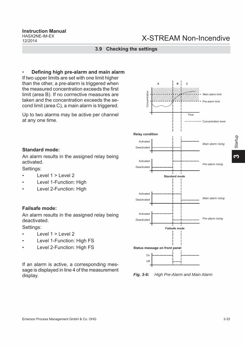
Emerson Process Management GmbH & Co. OHG 3-33
X-STREAM Non-IncendiveInstruction ManualHASX2NE-IM-EX12/2014
3S
tartu
p
• Defi ning high pre-alarm and main alarm
Standard mode:An alarm results in the assigned relay being activated.Settings: • Level 1 > Level 2 • Level 1-Function: High • Level 2-Function: High
If an alarm is active, a corresponding mes-sage is displayed in line 4 of the measurement display.
Failsafe mode:An alarm results in the assigned relay being deactivated.Settings: • Level 1 > Level 2 • Level 1-Function: High FS• Level 2-Function: High FS
Fig. 3-6: High Pre-Alarm and Main Alarm
3.9 Checking the settings
If two upper limits are set with one limit higher than the other, a pre-alarm is triggered when the measured concentration exceeds the fi rst limit (area B). If no corrrective measures are taken and the concentration exceeds the se-cond limit (area C), a main alarm is triggered.
Up to two alarms may be active per channel at any one time.
Con
cent
ratio
n
Activated
Time
Concentration level
Pre-alarm limit
Main alarm limit
Deactivated
Activated
Deactivated
Activated
Deactivated
Activated
Deactivated
A B C
On
Off
Relay condition
Standard mode
Failsafe mode
Status message on front panel
Main alarm rising
Pre-alarm rising
Main alarm rising
Pre-alarm rising
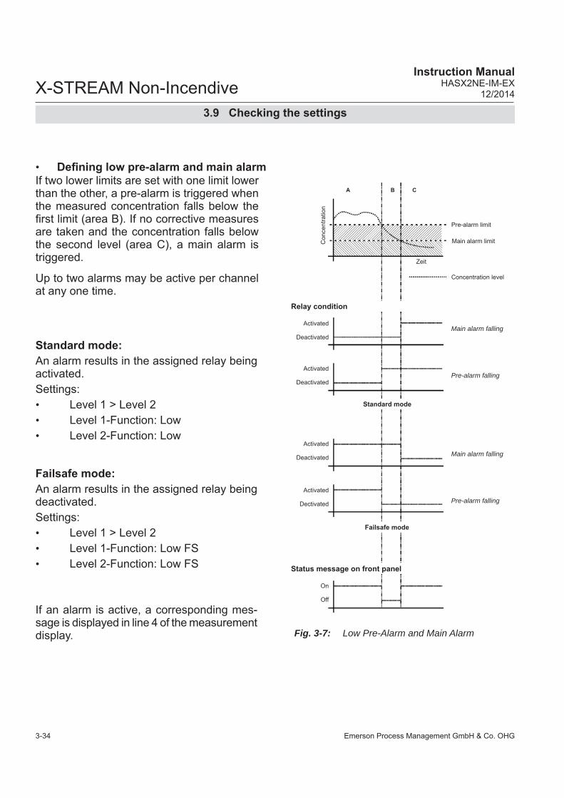
Emerson Process Management GmbH & Co. OHG3-34
X-STREAM Non-IncendiveInstruction Manual
HASX2NE-IM-EX12/2014
• Defi ning low pre-alarm and main alarm
Standard mode:An alarm results in the assigned relay being activated.Settings: • Level 1 > Level 2 • Level 1-Function: Low • Level 2-Function: Low
Failsafe mode:An alarm results in the assigned relay being deactivated.Settings: • Level 1 > Level 2 • Level 1-Function: Low FS• Level 2-Function: Low FS
If an alarm is active, a corresponding mes-sage is displayed in line 4 of the measurement display. Fig. 3-7: Low Pre-Alarm and Main Alarm
3.9 Checking the settings
If two lower limits are set with one limit lower than the other, a pre-alarm is triggered when the measured concentration falls below the fi rst limit (area B). If no corrective measures are taken and the concentration falls below the second level (area C), a main alarm is triggered.
Up to two alarms may be active per channel at any one time.
Con
cent
ratio
nActivated
Zeit
Concentration level
Pre-alarm limit
Main alarm limit
Deactivated
Activated
Deactivated
Activated
Deactivated
Activated
Dectivated
A B C
On
Off
Relay condition
Failsafe mode
Status message on front panel
Standard mode
Main alarm falling
Pre-alarm falling
Main alarm falling
Pre-alarm falling

Emerson Process Management GmbH & Co. OHG 3-35
X-STREAM Non-IncendiveInstruction ManualHASX2NE-IM-EX12/2014
3S
tartu
p
The most important parameters have now been checked and the unit’s settings adjusted to your needs.A backup copy of these confi guration data can now be made and saved.
3.9 Checking the settings
Press the LEFT key until the SETUP menu is displayed, and from there open the SAVE-LOAD menu.
Save-Load CfgData > SvcPort! SvcPort > CfgData..Verify!
Page 1
Page 22
FactData > CfgData..CfgData > UserData.. UserData > CfgData..
Now select the “CfgData > UserData” line and press ENTER.
Press the DOWN key to reach page 2.
3.9.6 Backing up the settings
Installed options..Communication..Alarms.. Save-Load..
Page 2
CfgData>UserData Are you sure?No!Yes!
A new window comes up to confi rm the action: Select the line Yes! and press the ENTER key: Another windows shows the current status.

Emerson Process Management GmbH & Co. OHG3-36
X-STREAM Non-IncendiveInstruction Manual
HASX2NE-IM-EX12/2014
3.9 Checking the settings
The unit is now saving a copy of the current confi guration data (the so-called CfgData dataset) in a special area of memory labelled UserData. This dataset can be used to reset the unit later if, for example, later incorrect settings render the unit unusable.If, during the analyzer startup up, the Cfg-Data checksum is found to be incorrect, the UserData dataset is loaded, to ensure the instrument remains usable.Further changes to the confi guration will only be stored in the CfgData dataset until manu-ally saved to UserData.
Upon completion of the saving process a confi rmation message will be displayed.
You have now completed checking the analyzer setup: Press the MEASURE key to return to the measurement display.
(i)
-COMMAND EXECUTED-
Copying data - PLEASE WAIT -
Procedure X:E000
We recommend to perform at least a zero calibration, after startup of the instrument, to ensure proper measuring results.See Chapter 4 for information on how to per-form a manual calibration. If your instrument features a valve block,
X-STREAM X2 instruction manual for a comprehensive description of calibration procedures.

Emerson Process Management GmbH & Co. OHG 4-1
X-STREAM Non-IncendiveInstruction ManualHASXENE-IM-EX12/2014
4M
aint
enan
ce
Chapter 4Service and Maintenance
EXPLOSION HAZARD WHEN OPEN
Service or replacement of safety related components or requiring to open the instrument are permitted only if no hazardous atmosphere is present and both the instrument and connected circuitry are de-energized!Depending on the local regulation this may require a competent hot work supervisor to issue a hot work permit.
EXPLOSION HAZARD
Inspection, maintenance and service must only be carried out by trained personnel, considering all related standards e.g. for „Inspection and maintenance of electrical installations in hazardous areas“ or „Equipment repair, overhaul and reclamation“.All applicable standards for servicing and maintaining equipment in hazardous areas have to be considered!
Note!This chapter deals with service and maintenance procedures related to explosion protection only!More detailled instructions about servicing and maintaining general purpose components of X-STREAM X2 gas analyzers are subject of the gas analyzer instruction manual.
4.1 Maintenance Safety Instructions

Emerson Process Management GmbH & Co. OHG4-2
X-STREAM Non-IncendiveInstruction Manual
HASX2NE-IM-EX12/2014
EXPLOSION HAZARD BY MODIFICATION
Modifi cations affecting the integrity of type of protection (e.g. affi xing additional threads) are NOT PERMITTED!Violation may cause an explosion and/or personal injury or death!
EXPLOSION HAZARD BY REPLACED PARTS
Replacement of parts found defective is permitted only by using original parts!Any addition, substitution, or replacement of components installed on or in this device, must be certifi ed to meet the hazardous area classifi cation that the device was certifi ed to prior to any such component addition, substitution, or replacement. After maintenance or replacement of components relevant for explosion protection, an authority has to certify, that the analyzer still meets the requirements for explosion protection. A related document must be issued and/or a label be applied to the analyzer before setting into operation.Any modifi cations to the device, not authorized by Emerson Process Management will void the product certifi cation(s).Violation voids the approvals and may cause explosions!
HAZARDS BY GASES
When measuring fl ammable or toxic gases, it is recommended to purge the system with air or an inert gas, e.g. nitrogen, prior to opening the gas paths.Violation may cause an explosion and/or personal injury or death!
4.1 Maintenance Safety Instructions
Emerson Process Management GmbH & Co. OHG 4-3
X-STREAM Non-IncendiveInstruction ManualHASXENE-IM-EX12/2014
4M
aint
enan
ce
4 Maintenance
To assure instrument performance and safety, the analyzer has to be checked regularly, at least once a year. During maintenance especially parts found relevant for explosion protection have to be taken into account. For non-incendi-ve X-STREAM gas analyzers this par-ticularly includes the enclosure and the corresponding gaskets. Enclosure and gaskets need to be checked for dama-ges, and gaskets must be suffi ciently tight ( leakage test, page 4-4).During maintenance, the optional gas samp-ling pump has to be evaluated for grinding moving parts, creating sparks. Internal connectors have to be regarded accordingly. They need to be fi xed, to not produce sparks during operation.
4.2 Maintenance Instructions
Parts found a potential risk of hot spots, arc or sparcs must be replaced!The user/owner has to take re-sponsibility to modify the main-tenance interval regarding the conditions at site (infl uence of gases or ambient atmosphere on material in contact with sample/calibration gas or which are re-levant for explosion protection [e.g. enclosure sealing]).
By visual inspection of the interior of the ana-lyzer, especially the electrical components, it must be verifi ed that components are not overloaded. Overloaded components may become hot, and thus become a source of ignition! An indicator for overload may be discoloration.
4.3 Gas PathsDetailled information about maintenance, replacement of components and performing a gas paths leakage test are available in the X-STREAM X2 series general instruction manual.

Emerson Process Management GmbH & Co. OHG4-4
X-STREAM Non-IncendiveInstruction Manual
HASX2NE-IM-EX12/2014
4.4 Checking Modifi ed or Repaired Analyzers Modifi cations on non-incendive X-STREAM gas analyzers which infl uence the integrity of protection type or analyzer temperature are permissible only, if the modifi ed analyzer are inspected by a licensed test laboratory, or if an authorized expert has evaluated the modifi cations.
In case of repair infl uencing the protection type, the repaired parts should be drawn to suitable check routines and must be con-trolled. These inspections need not necessa-rily to be carried out by EMERSON Process Management, but can also be performed by local trained service personnel.
To run the test procedure, the following pre-parations have to be encountered: • Disconnect from power, or de-energize
the analyzer.• Disconnect containment system fi ttings
from external gas pipes.• Disconnect one containment system gas fi tting inside the analyzer and close the other fi tting.
Note: Now it need to be possible to pressurize the housing supplying an external gas (e.g. compressed air) to the gas inlet.
• Supply compressed air from an external source as described in Section 4.3.1.2 on the following page.
Required Tools:• Pressure gauge with a measuring range
of 50 to 100 mbar (0.7 to 1.5 psig; reso-lution of 0.1 mbar/ 0.0015 psig).
• Flow meter with a measuring range of 5 to 10 l/min; resolution of 0.1 l/min.
• Span gas: Instrumental air or nitro-gen; pressure reduced to 1.500 mbar (22 psig).
• Pressure regulator to reduce pressure to 25 mbar (0.4 psig)
• Equipment for fl ow control • 1 plug to shut off the gas outlet
(size: 6 mm / 1⁄4“)
The compressed air must be dry and free from dust, oil and corrosive components!
Local regulations may require to apply additional markings to repaired equipment in hazar-dous areas!
4.4.1 Enclosure Leakage Test 4.4.1.1 Preparation
4.4 Checking Modifi ed or Repaired Analyzers

Emerson Process Management GmbH & Co. OHG 4-5
X-STREAM Non-IncendiveInstruction ManualHASXENE-IM-EX12/2014
4M
aint
enan
ce
The housing needs to be controlled on leaka-ges with a pressure of 25 mbar (0.4 psig). The following steps have to be provided:• Modify like described on Section 4.3.1.1.• Supply a pressure of 25 mbar to the ana-
lyzer housing and take care of the fl ow meter display.
The test is passed, if the measured value does not exceed the following max. value:Permissible fl ow: 3 l/min max.
4.4.1.2 Run Leakage Test
Fig. 4-1: Assembly for Check Routines
4.4.1.3 Startup After Test ProcedureAll modifi cations described in Section 4.3.1.1 have to be cancelled. Especially the gas fi ttings‘ tight assemblies need to be checked.
4.4 Checking Modifi ed or Repaired Analyzers
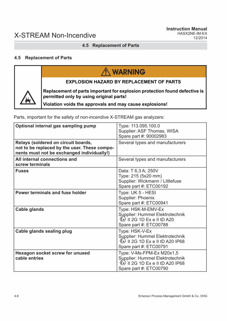
Emerson Process Management GmbH & Co. OHG4-6
X-STREAM Non-IncendiveInstruction Manual
HASX2NE-IM-EX12/2014
4.5 Replacement of Parts
4.5 Replacement of Parts
EXPLOSION HAZARD BY REPLACEMENT OF PARTS
Replacement of parts important for explosion protection found defective is permitted only by using original parts!Violation voids the approvals and may cause explosions!
Parts, important for the safety of non-incendive X-STREAM gas analyzers:
Optional internal gas sampling pump Type: 113.095.100.0Supplier: ASF Thomas, WISASpare part #: 90002983
Relays (soldered on circuit boards,not to be replaced by the user. These compo-nents must not be exchanged individually!)
Several types and manufacturers
All internal connections and screw terminals
Several types and manufacturers
Fuses Data: T 6,3 A; 250V Type: 215 (5x20 mm)Supplier: Wickmann / LittlefuseSpare part #: ETC00192
Power terminals and fuse holder Type: UK 5 - HESISupplier: PhoenixSpare part #: ETC00941
Cable glands Type: HSK-M-EMV-ExSupplier: Hummel Elektrotechnik II 2G 1D Ex e II tD A20Spare part #: ETC00788
Cable glands sealing plug Type: HSK-V-ExSupplier: Hummel Elektrotechnik II 2G 1D Ex e II tD A20 IP68Spare part #: ETC00791
Hexagon socket screw for unused cable entries
Type: V-Ms-FPM-Ex M20x1,5Supplier: Hummel Elektrotechnik II 2G 1D Ex e II tD A20 IP68Spare part #: ETC00790

Emerson Process Management GmbH & Co. OHG 4-7
X-STREAM Non-IncendiveInstruction ManualHASXENE-IM-EX12/2014
4M
aint
enan
ce
4.6 Perform a CalibrationThe following steps describe, how to per-form a manual calibration. If your instrument features a valve block, X-STREAM X2 instruction manual for a comprehensive de-scription of calibration procedures.Note!To achieve best and proper measuring re-sults, it is recommended to perform zero and span calibrations on a regular weekly basis. Also, a span calibration must always be pre-ceded by a zero calibration!
Zero calibrationTo perform a zero calibration supply either nitrogen (N2) or another suitable zero gas [conditioned ambient air or industrial air (NOT for oxygen measurement!)] to the gas path. The concentration of the component of inte-rest is specifi ed as set point and during zero calibration, the actual value is assigned this concentration
Span calibrationSupply span gases with concentrations of 80 % to 110 % of the upper measuring range limit to the gas path. (Using lower concentra-tions may decrease accuracy when measu-ring above the span gas concentration) The concentration of the component of interest is specifi ed as set point, and during span calibration the actual value is assigned this concentration! Note!If the oxygen concentration is known, ambi-ent air may be used for an oxygen channel span calibration.
4.6 Perform a Calibration

Emerson Process Management GmbH & Co. OHG4-8
X-STREAM Non-IncendiveInstruction Manual
HASX2NE-IM-EX12/2014
4.6 Perform a Calibration
Before performing any actions, make sure the required calibration gas is applied and fl owing!Supply all calibration gases with the same fl ow and pressure as the sample gas (re-commended: approx. 1 l/min), and utilizing the correct gas fi tting.Ensure the warm-up time after switching on has elapsed! Warm-up time depends on installed measuring system and confi guration, measurement specifi cations in section 1.7!
Do NOT calibrate the TRACE MOISTURE sensor (tH2O)!The sensor is completely calibrated with all calibration data stored in its fl ash memory and does not require recalibration:If the sensor is included into a calibration procedure, it might end up with a wrong ca-libration and unusable sensor. Therefore the analyzer's trace moisture measurement channel is confi gured to be excluded from autocalibration procedures, by default calibra-ting all channels. This exclusion is done by factory setup and cannot be changed.For proper measurement results we recommend to exchange the sensor regularly after 12 months of operation. For instructions on how to exchange, X-STREAM X2 instruction manual
Do NOT calibrate the TRACE OXYGEN sensor (tO2) without prior reading the instructions!Together with each sensor an installation manual is shipped, also giving comprehensive calibration information. Read these information prior intending to activate calibration procedures!
OPERATION AT LOW TEMPERATURES
When operating an instrument at temperatures below 0 °C (32 °F), do NOT apply gas nor operate the internal pump before the warmup time has elapsed!Violation may result in condensation inside the gas paths or damaged pump diaphragm!

Emerson Process Management GmbH & Co. OHG 4-9
X-STREAM Non-IncendiveInstruction ManualHASXENE-IM-EX12/2014
4M
aint
enan
ce
Calibration gases
ZeroGas: 0.0 ppmSpanGas: 500.0 ppm
4.6.1 Preparing Calibrations
Before starting calibrations it is required to tell the instrument the calibration gas concen-trations.
Starting from the measurement screen press the DOWN key to open the MAIN MENU, enter the SETUP-CALIBRATION.. menu and directly enter the CALIBRATION GASES.. menu.
Enter the concentration value for the zero gas to be used during zero calibration.
Enter the concentration value for the span gas to be used during span calibration.
Note!The units for the calibration gases are taken from the related entry in the display setup menu.
When done, press the key to return to the CALIBRATION menu.
Setup..Calibration..Calibration gases..
Multi-channel unit:Select the channel to be calibrated in the SELECT COMPONENT menu.
Multi-channel unit:Press the key to enter the SELECT COM-PONENT menu to change the settings for a different channel.
4.6 Perform a Calibration

Emerson Process Management GmbH & Co. OHG4-10
X-STREAM Non-IncendiveInstruction Manual
HASX2NE-IM-EX12/2014
4.6 Perform a Calibration
Calibration gases...Tol.Check: OffHold on cal: OnPurge time: 15 s
Example:Measuring range: 0 ... 50 %Zero gas: 0 %Span gas: 50 %Situation:Due to a fault zero gas is supplied to carry out a span calibration, instead of span gas.Tolerance check disabled (Off):The analyzer calibrates the span with the wrong gas resulting in an analyzer out of tune. Tolerance check enabled (10%; AutoOff):Starting a span calibration with zero gas connected instead of span gas, the analyzer gives an error message and stops calibrating because the measured (expected span gas) value differs more than 10 % from the upper measuring range limit.
By default the option "Tol.Check" (tolerance check) is disabled (Off). So tolerance check helps avoiding calibrating with a wrong gas applied (e.g. starting a span calibration while zero gas is fl owing) resulting in an instrument out of tune (see example to the left side).
With tolerance check enabled (10%) during calibration the analyzer checks that the en-tered (setpoint) values for zero gas and span gas are reasonable compared to the currently fl owing calibration gas. If this gas concen-tration differs more than 10 % of measuring range from zero gas (during zero calibration) or span gas setup (during span calibration), calibration is aborted and a maintenance request alarm is set ( LED and optional relay output). Resetting the alarm requires to per-form a valid calibration or to confi rm it within the CONTROL - ACKNOWLEDGEMENTS.. screen.The 3rd option (AutoOff) has the same func-tionality as 10% except that the maintenance request is reset after 2-3 minutes.
There are still situations when tolerance check must be disabled, e.g. when calibrating after changing the span gas concentration. In this cases select Off.
Purge time: 15 s
Note!The last line ("purge time") shows up only if the valve option is other than none (see INSTALLED OPTIONS menu) and is used for advanced, remote and unattended cali-brations only..
Calibration gases...Tol.Check: OffHold on cal: OnPurge time: 15 sPurge time: 15 s

Emerson Process Management GmbH & Co. OHG 4-11
X-STREAM Non-IncendiveInstruction ManualHASXENE-IM-EX12/2014
4M
aint
enan
ce
4.6.2 Manual Calibration
Zero calibration..Span calibration..Adv.Calibration..Apply gas..
4.6.2.1 Manual Zero Calibration
CANCEL calibration!START calibration!ZeroGas 0.000 ppmCO2.1 0.200 ppm
Control..Starting from the measurement screen press the DOWN key to open the MAIN MENU and enter the CONTROL.. menu.
To start a zero calibration select the fi rst line:
Multi-channel unit:Select the channel to be calibrated in the SELECT COMPONENT menu.
Before selecting any further line make sure the required calibra-tion gas is applied and fl owing!Supply all calibration gases with the same fl ow as the samp-le gas (recommeded approx. 1 l/min), pressureless and utilizing the right gas fi ttingwhile cali-brating, the analyzer compares the set values for zero or span gas with the actual value.Ensure the warm-up time after switching on has elapsed! Warm-up time is 15 to 50 minutes depending on installed measu-ring system and confi guration!
The fi rst line gives you the choice to cancel the procedure now.Select the second line to start the calibra-tion.Line 3 shows the calibration gas setup (here: required zero gas concentration is 0.000 ppm), while line 4 shows the currently measured gas concentration.
4.6 Perform a Calibration

Emerson Process Management GmbH & Co. OHG4-12
X-STREAM Non-IncendiveInstruction Manual
HASX2NE-IM-EX12/2014
Gasfl ow ZeroGasCO2.1 0.500 ppmProcedure ZeroingTime 10 s
CANCEL calibration!START calibration!SpanGas 20.000 ppmCO2.1 16.200 ppm
4.6.2.2 Manual Span Calibration
After having started the calibration, watch the screen for information about the status:The fi rst lines shows the gas (channel) to be calibrated as well as the currently measured concentration (after zero calibration this value should be set to "0").The line "Procedure" shows what's currently happening (Zeroing = calibration ongoing; Purging = waiting for measuring system to be fi lled with currently fl owing gas; None = calibration fi nished), while the last line shows the remaining time till end of calibration (countdown starting from 40 seconds).When fi nished press the LEFT key two times to return to eitherthe SELECT COMPONENT menu (multi channel analyzer only), select another chan-nel to perform the steps described above to zero calibrate this channel, too,or the CONTROL.. menu, which allows you to start a span calibration. The procedure and screens look similiar to those of a zero cali-bration:
Multi-channel unit:Select the channel to be calibrated in the SELECT COMPONENT menu.
Before selecting any further line make sure the required calibra-tion gas is applied and fl owing!
The fi rst line gives you the choice to immedi-ately cancel the procedure.Select the second line to start the calibra-tion.Line 3 shows the calibration gas setup (here: required span gas concentration is 20 ppm), while line 4 shows the currently measured gas concentration.
Select SPAN CALIBRATION...
4.6 Perform a Calibration

Emerson Process Management GmbH & Co. OHG 4-13
X-STREAM Non-IncendiveInstruction ManualHASXENE-IM-EX12/2014
4M
aint
enan
ce
Gasfl ow SpanGasCO2.1 20.000 ppmProcedure SpanningTime 10 s
After having started the calibration watch the screen for status information:The display shows the currently fl owing gas, the gas (channel) to be calibrated as well as the currently measured concentration (after span calibration it should be set to the expec-ted value) and a countdown for the current procedure:The line "Procedure" shows what's currently happening (Spanning = calibration ongoing; Purging = waiting for measuring system to be fi lled with currently fl owing gas; None = calibration fi nished), while the last line shows the remaining time till end of calibration (countdown starting from 40 seconds).
When fi nished, either pressthe LEFT key two times to return to the SELECT COMPONENT menu (multi channel analyzer only), select another channel and perform the steps described above to zero calibrate this channel, too,or the HOME key to return to the measurement screen to fi nish with manual calibration pro-cedures.
4.6 Perform a Calibration

Emerson Process Management GmbH & Co. OHG4-14
X-STREAM Non-IncendiveInstruction Manual
HASX2NE-IM-EX12/2014

Emerson Process Management GmbH & Co. OHG 5-1
X-STREAM Non-IncendiveInstruction ManualHASX2NE-IM-EX12/2014
5D
ism
ount
ing
Chapter 5Dismounting and Disposal
5.1 Dismounting and Diposal of the Analyzer
HAZARDS FROM DISMOUNTING
Dismounting instruments installed in hazardous area requires special instructions to be followed! Only trained personnel, observing all applicable technical and legal requirements, and aware of the possible risks is permitted to dismount these analyzers.Failure to follow may result in explosion, death or personal injury!
EXPLOSION HAZARD WHEN OPEN
Dismounting requires to open the instrument and is permitted only if no hazardous atmosphere is present and both the instrument and connected circuitry are de-energized!Depending on the local regulation this may require a competent hot work supervisor to issue a hot work permit.Failure to follow may result in explosion!
HEAVY INSTRUMENT
X-STREAM fi eld housings, intended for outside and wall mounted use, weigh between 26 kg (57 lb) and 45 kg (99 lb) depending on options installed.Support the instrument before loosening the fi xing screws (risk of dropping instrument).Two people and/or lifting equipment is required to lift and carry these units.Failure to follow may result in personal injury!

Emerson Process Management GmbH & Co. OHG5-2
X-STREAM Non-IncendiveInstruction Manual
HASX2NE-IM-EX12/2014
5 Dismounting & Disposal
When the instrument has reached the end of its useful life,
When the instrument has reached the end of its useful life, do not dispose of it together with general domestic waste!This instrument has been made of materials to be recycled by recyclers speci-alised in this fi eld. Let the instrument and the packing material duly and envi-ronmently friendly be disposed of. Ensure the equipment is free of dangerous and harmful substances (decontaminated).Take care of all local regulations for waste treatment.Consider the X-STREAM X2 instruction manual for information on dismounting and disposal of analyzers.
• purge all gas lines with inert gas • ensure all gas lines are pressureless• disconnect all gas lines • switch off power and signal lines• disconnect and remove all electrical con-
nections• fi ll out the Declaration of Decontamination
( A-21) properly
• hand over the dismounted instrument together with the Declaration of Deconta-mination to a disposal specialist. The dis-posal specialist then has to disassemble the instrument, and recycle and dispose it in compliance with all applicable waste treatment regulations.
GASES HAZARDOUS TO HEALTH
Follow the safety precautions for all applied gases and gas cylinders.Before opening the gas lines, they must be purged with air or neutral gas (N2) to avoid danger from escaping toxic, fl ammable, explosive or hazardous gases.

Emerson Process Management GmbH & Co. OHG A-1
X-STREAM Non-IncendiveInstruction ManualHASX2NE-IM-EX12/2014
AA
ppen
dix
Appendix
This chapter contains:
CSA Certifi cate of Compliance page A-2
Block diagrams page A-9
Declaration of Decontamination page A-14
Assignment of Terminals and Sockets page A-15

Emerson Process Management GmbH & Co. OHGA-2
X-STREAM Non-IncendiveInstruction Manual
HASX2NE-IM-EX12/2014
A.1 CSA Certifi cate of Compliance
Certificate of ComplianceCertificate: Master Contract:
Project: Date Issued:
Issued to: Emerson Process Management
GmbH & Co. OHGIndustriestrasse 1Hasselroth, 63594GermanyAttention: Uwe Schmidt
The products listed below are eligible to bear the CSAMark shown with adjacent indicators 'C' and 'US' for
Canada and US or with adjacent indicator 'US' forUS only or without either indicator for Canada only.
Issued by:
PRODUCTSCLASS 2258 82
CLASS 2258 02CLASS 8721 85
CLASS 8721 05
CLASS 8721 05 - LABORATORY ELECTRICAL EQUIPMENT
CLASS 8721 85 - ELECTRICAL EQUIPMENT FOR LABORATORY USE (Certified to U.S. Standards)
X-STREAM (XLF) or X-STREAM Enhanced Field Housing Gas Analyzer (XEF)
X-STREAM (X2GP) or X-STREAM Enhanced (XEGP) General Purpose Gas Analyzer:
X-STREAM Gas Analyzer Core (XCA)
A.1 CSA Certifi cate of Compliance

Emerson Process Management GmbH & Co. OHG A-3
X-STREAM Non-IncendiveInstruction ManualHASX2NE-IM-EX12/2014
AA
ppen
dix
A.1 CSA Certifi cate of Compliance
Certificate: Master Contract:
Project: Date Issued:
X-STREAM Gas Analyzer Core Compact (XCK)
X-STREAM (X2GK) or X-STREAM Enhanced (XEGK) General Purpose Compact Gas Analyzer:
X-STREAM X100 Compact Gas Analyzer (X100GK):
X-STREAM (XXF) or X-STREAM Enhanced Field Housing Gas Analyzer (XDF)
X-STREAM (X2GC or X2GK)or X-STREAM Enhanced (XEGC or XEGK)General Purpose CompactGas Analyzer X-STREAM Compact Gas Analyzer Core (XCC or XCK):
Conditions of Acceptability
CLASS 2258-02 PROCESS CONTROL EQUIPMENT – For Hazardous Locations
CLASS 2258-82 PROCESS CONTROL EQUIPMENT – For Hazardous Locations – Certified to U.S.Standards.
X-Stream FD (XFD)
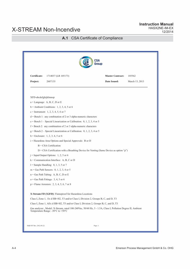
Emerson Process Management GmbH & Co. OHGA-4
X-STREAM Non-IncendiveInstruction Manual
HASX2NE-IM-EX12/2014
A.1 CSA Certifi cate of Compliance
Certificate: Master Contract:
Project: Date Issued:
X-Stream FD (X2FD)

Emerson Process Management GmbH & Co. OHG A-5
X-STREAM Non-IncendiveInstruction ManualHASX2NE-IM-EX12/2014
AA
ppen
dix
A.1 CSA Certifi cate of Compliance
Certificate: Master Contract:
Project: Date Issued:

Emerson Process Management GmbH & Co. OHGA-6
X-STREAM Non-IncendiveInstruction Manual
HASX2NE-IM-EX12/2014
A.1 CSA Certifi cate of Compliance
Certificate: Master Contract:
Project: Date Issued:
X-STREAM FD (XEFD)
(XEF)
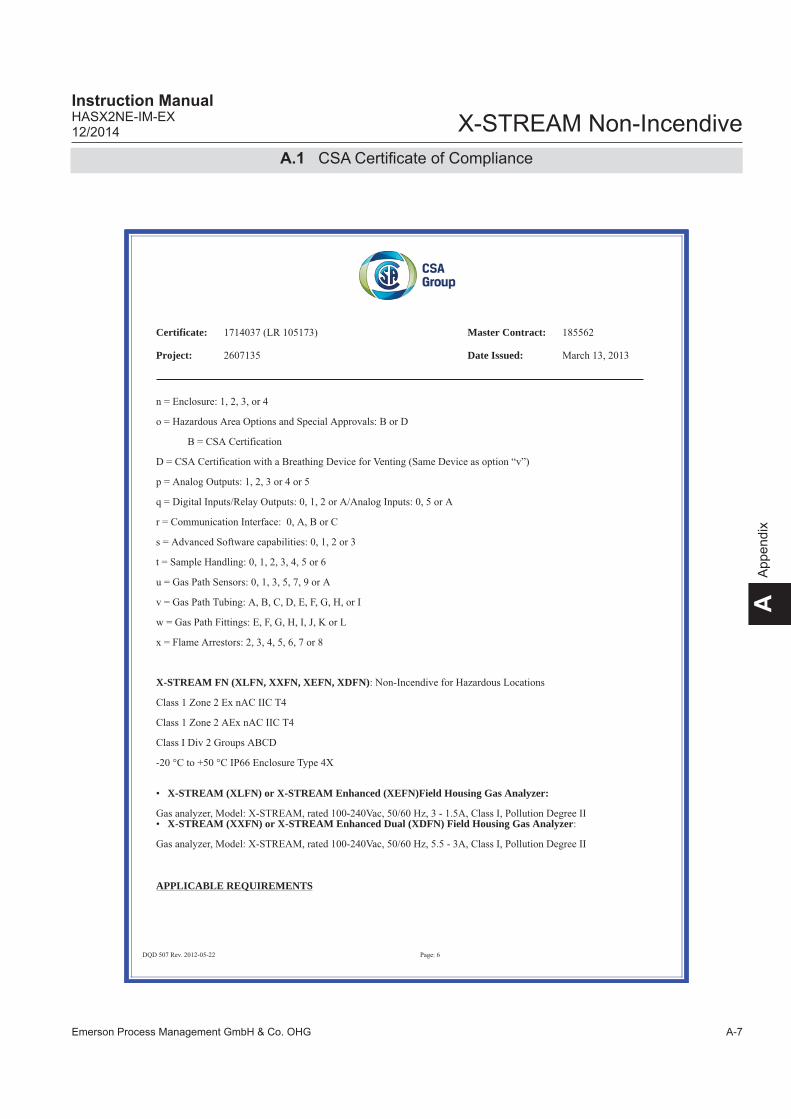
Emerson Process Management GmbH & Co. OHG A-7
X-STREAM Non-IncendiveInstruction ManualHASX2NE-IM-EX12/2014
AA
ppen
dix
A.1 CSA Certifi cate of Compliance
Certificate: Master Contract:
Project: Date Issued:
X-STREAM FN (XLFN, XXFN, XEFN, XDFN)
X-STREAM (XLFN) or X-STREAM Enhanced (XEFN)Field Housing Gas Analyzer:
X-STREAM (XXFN) or X-STREAM Enhanced Dual (XDFN) Field Housing Gas Analyzer
APPLICABLE REQUIREMENTS
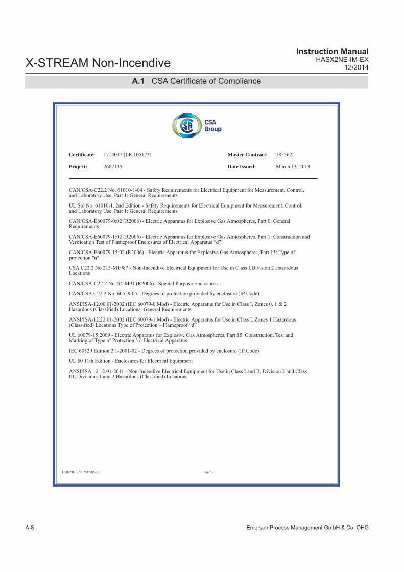
Emerson Process Management GmbH & Co. OHGA-8
X-STREAM Non-IncendiveInstruction Manual
HASX2NE-IM-EX12/2014
A.1 CSA Certifi cate of Compliance
Certificate: Master Contract:
Project: Date Issued:
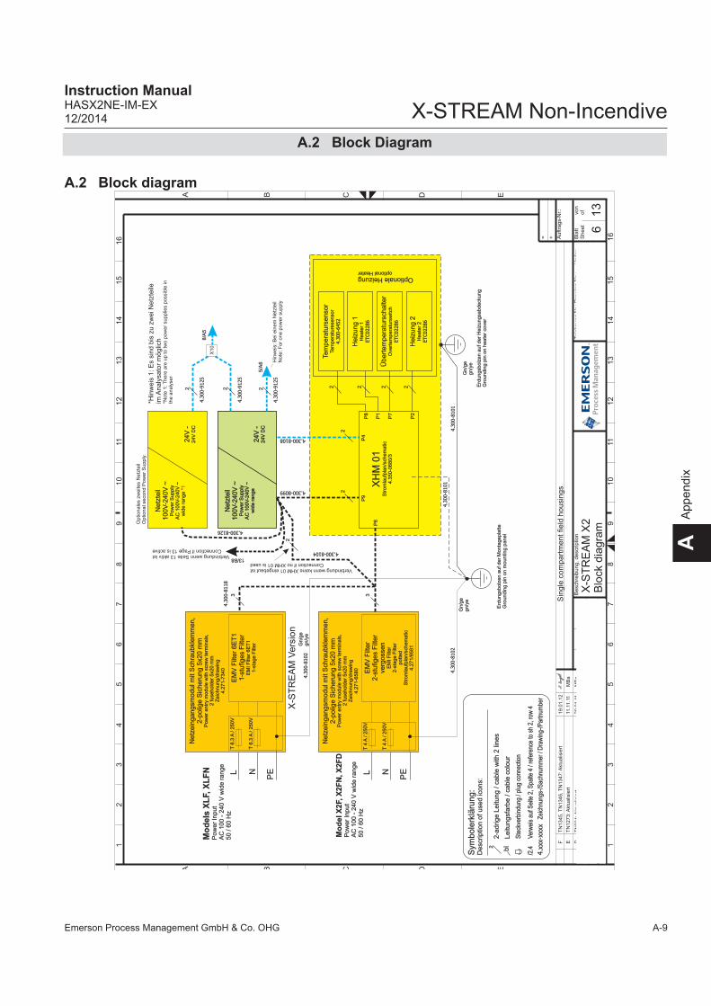
Emerson Process Management GmbH & Co. OHG A-9
X-STREAM Non-IncendiveInstruction ManualHASX2NE-IM-EX12/2014
AA
ppen
dix
A.2 Block Diagram
A.2 Block diagram
Erd
un
gsb
olz
en
au
f d
er
Mo
nta
ge
pla
tte
Gro
un
din
g p
in o
n m
ou
ntin
g p
an
el
Erd
un
gsb
olz
en
au
f d
er
He
izu
ng
sab
de
cku
ng
Gro
un
din
g p
in o
n h
ea
ter
cove
r
Gn
/ge
gn
/ye
4.3
00-8
101
4.3
00-8
101
Sin
gle
co
mp
art
me
nt
field
ho
usi
ng
s
L N
PE
Netz
ein
gangsm
odul m
it S
chra
ubkl
em
men,
2-p
olig
e S
icheru
ng 5
x20 m
mP
ow
er
en
try
mo
du
le w
ith s
cre
w t
erm
ina
ls,
2 f
use
ho
lde
r 5x2
0 m
mZ
eic
hn
un
g/d
raw
ing
4.2
71
-65
80
Mo
de
l X
2F,
X2
FN
, X
2F
DP
ow
er
Inpu
tA
C 1
00
- 2
40
V w
ide r
ang
e50 /
60 H
zE
MV
Filt
er
2-s
tufig
es
Filt
er
verg
oss
en
EM
I F
ilte
r2
-sta
ge
Filt
er
po
tte
dS
tro
mla
ufp
lan
/sch
em
atic
4.2
71
/65
81
Gn
/ge
gn
/ye
4.3
00-8
102
T 4
A /
25
0V
T 4
A /
25
0V
T 6
.3 A
/ 2
50
VL N
PE
Netz
ein
gangsm
odul m
it S
chra
ubkl
em
men,
2-p
olig
e S
icheru
ng 5
x20 m
mP
ow
er
en
try
mo
du
le w
ith s
cre
w t
erm
ina
ls,
2 f
use
ho
lde
r 5
x20
mm
Ze
ich
nun
g/d
raw
ing
4.2
71
-73
40
Mo
de
ls X
LF, X
LF
NP
ow
er
Inpu
tA
C 1
00 -
24
0 V
wid
e r
ang
e50
/ 6
0 H
z
T 6
.3 A
/ 2
50
V
EM
V F
ilter
6E
T1
1-s
tufig
es
Filt
er
EM
I F
ilte
r 6
ET
11
-sta
ge
Filt
er
4.3
00-8
102
Gn
/ge
gn
/ye
4.300-8099
4.300-8108
XH
M 0
1S
tro
mla
ufp
lan
/sch
em
atic
4.3
50
-06
80
/3
P6
2
P9
2
P4
2P
8
2P
2
2P
7
Optionale Heizungoptional Heater
P1
Tem
pera
turs
enso
rTe
mp
era
ture
sen
sor
4.3
00-6
452
2
4.300-8104
3
Verbindung wenn keine XHM 01 eingebaut istConnection if no XHM 01 is used
2
4.3
00-8
118
3
Heiz
ung 1
He
ate
r 1
ETC02286
Heiz
ung 2
He
ate
r 2
ETC02286
Übert
em
pera
turs
chalte
rO
vert
em
pe
ratu
rsw
itch
ETC02286
2-a
drige L
eitu
ng / c
able
with
2 li
nes
Sym
bole
rklä
rung
:D
esc
riptio
n o
f use
d ic
ons:
Leitu
ngsf
arb
e / c
able
colo
ur
bl
Ste
ckve
rbin
dung
/ pl
ug c
onne
ctio
n
/2.4
Ver
wei
s au
f Sei
te 2
, Spa
lte 4
/ re
fere
nce
to s
h 2,
row
4
4.x
xx-x
xxx
Zei
chnu
ngs-
/Sac
hnum
mer
/ D
raw
ing-
/Par
tnum
ber
2
Netz
teil
100V
-240V
~P
ow
er
Su
pp
lyA
C 1
00
V-2
40
V ~
wid
e r
an
ge
24V
-2
4V
DC
Netz
teil
100V
-240V
~P
ow
er
Su
pp
lyA
C 1
00
V-2
40
V ~
wid
e r
an
ge
*1
24V
-2
4V
DC
Netz
teil
100V
-240V
~P
ow
er
Su
pp
lyA
C 1
00
V-2
40
V ~
wid
e r
an
ge
24V
-2
4V
DC
2
4.3
00-9
125
5/A
6
Verbindung wenn Seite 13 aktiv istConnection if Page 13 is active
13/B8
4.300-8126
Op
tion
ale
s zw
eite
s N
etz
teil
Op
tion
al s
eco
nd
Po
we
r S
up
ply
*Hin
weis
1: E
s si
nd b
is z
u z
wei N
etz
teile
im
Analy
sato
r m
öglic
h*N
ote
1: T
he
re a
re u
p t
o t
wo
po
we
r su
pp
lies
po
ssib
le in
the
an
aly
ser
Hin
we
is:
Be
i ein
em
Ne
tzte
ilN
ote
: F
or
on
e p
ow
er
sup
ply
2
4.3
00-9
125
8/A
5
2
4.3
00-9
125
X1
0
6
E
Mic
roIn
de
xÄ
nd
eru
ng
, re
visi
on
Da
tum
Na
me
Be
arb
.
Ge
pr.
20
__
_D
atu
mN
am
e
Be
sch
reib
un
g,
de
scrip
tion
Ze
ich
nu
ng
-Nr.
: D
raw
ing
-No
.:In
de
x
Ide
nt-
Nr.
:
Bla
ttS
he
et
von
of
Au
ftra
gs-
Nr.:
+=
DCBA
EDCBA
12
34
56
78
910
1112
13
14
15
16
12
34
56
78
910
1112
13
14
15
16
4.3
00
-51
58
/407
02
.10
.W
alth
er
Sch
mid
tX
-ST
RE
AM
X2
Blo
ck d
iagra
m0
3.1
0.
BN
eu
e G
eh
äu
seva
ria
nte
n h
inzu
1
2.0
8.0
9M
Ba
CT
N8
46
: T
race
Mo
istu
re h
inzu
11
.11
.10
MB
a
DT
N9
34
: Akt
ua
lisie
rt2
0.0
1.1
1M
Ba
13
F
EM
Ba
11.1
1.1
1T
N1
27
3: A
ktu
alis
iert
F1
9.0
1.1
2T
N1
34
5, T
N1
34
6, T
N1
34
7: A
ktu
alis
iert
X-S
TRE
AM
Ver
sion

Emerson Process Management GmbH & Co. OHGA-10
X-STREAM Non-IncendiveInstruction Manual
HASX2NE-IM-EX12/2014
A.2 Block Diagram
T 6
.3 A
/ 2
50V
L N
PE
Ne
tze
ingan
gsm
od
ul m
it S
chra
ubkl
em
me
n,
2-p
olig
e S
iche
run
g 5
x20 m
mP
ow
er
entr
y m
odule
with
scr
ew
term
inals
,2 fuse
hold
er
5x2
0 m
mZ
eic
hnung/d
raw
ing
4.2
71-7
340
Po
wer
Inpu
tA
C 1
00 -
240
V w
ide r
an
ge
50 / 6
0 H
z
T 6
.3 A
/ 2
50V
EM
V F
ilter
6E
T1
1-s
tufig
es
Filt
er
EM
I F
ilter
6E
T1
1-s
tage F
ilter
XD
F, X
DF
N
Gn/g
egn/y
e
Erd
ungsb
olz
en a
uf der
Monta
gepla
tte
Gro
undin
g p
in o
n m
ountin
g p
anel
4.3
00-8
118
XH
M 0
1S
trom
laufp
lan/s
chem
atic
4.3
50-0
680/3
P6
2
P9
2
4.300-8108 P4
P8
P2
Gn/g
egn/y
e
P7
4.3
00-8
102
4.3
00-8
101
4.3
00-8
100
Optionale Heizungoptional Heater
P1
Tem
pe
ratu
rse
nso
rTe
mpera
ture
senso
r4.3
00-6
452
Erd
ungsb
olz
en a
uf
der
Trä
gerp
latt
eG
roundin
g p
in o
n m
ountin
g p
late
2 22
2
6
4.300-8113
32
4.300-8104
Verbindung wenn keine XHM 01 eingebaut istConnection if no XHM 01 is used
He
izu
ng 1
Heate
r 1
ETC02286
He
izu
ng 2
Heate
r 2
ETC02286
Üb
ert
em
pe
ratu
rsch
alte
rO
vert
em
pera
turs
witc
hETC02286
2-a
drige
Le
itun
g / c
able
with
2 li
nes
Sym
bo
lerk
läru
ng
:D
esc
riptio
n o
f use
d ic
on
s:
Leitu
ng
sfa
rbe / c
able
colo
ur
bl
Ste
ckve
rbin
dung
/ pl
ug c
onne
ctio
n
/2.4
Ver
wei
s au
f Sei
te 2
, Spa
lte 4
/ re
fere
nce
to s
h 2,
row
4
4.x
xx-x
xxx
Zei
chnu
ngs-
/Sac
hnum
mer
/ D
raw
ing-
/Par
tnum
ber
2
Netz
teil
10
0V
-240
V ~
Pow
er
Supply
AC
100V
-240V
~w
ide r
ange
24
V -
24V
DC
2
4.3
00-9
125
8/A
6
Netz
teil
10
0V
-240
V ~
Pow
er
Supply
AC
100V
-240V
~w
ide r
ange
24
V -
24V
DC
Netz
teil
10
0V
-240
V ~
Pow
er
Supply
AC
100V
-240V
~w
ide r
ange *
12
4V
-24V
DC
Netz
teil
10
0V
-240
V ~
Pow
er
Supply
AC
100V
-240V
~w
ide r
ange
24
V -
24V
DC
2
4.3
00-9
125
5/A
6
4.300-8126
Optio
nale
s zw
eite
s N
etz
teil
Optio
nal s
eco
nd P
ow
er
Supply
*Hin
weis
1: E
s si
nd b
is z
u z
wei N
etz
teile
im
Analy
sato
r m
öglic
h*N
ote
1: T
here
are
up t
o t
wo p
ow
er
supplie
s poss
ible
inth
e a
naly
ser
Hin
weis
: B
ei e
inem
Netz
teil
Note
: F
or
one p
ow
er
supply
2
4.3
00-9
125
8/A
5
2
4.3
00-9
125
X10
7
gg
E
Mic
roIn
de
xÄ
nd
eru
ng
, re
visi
on
Da
tum
Na
me
Be
arb
.
Ge
pr.
20
__
_D
atu
mN
am
e
Be
sch
reib
un
g,
de
scrip
tion
Ze
ich
nu
ng
-Nr.
: D
raw
ing
-No
.:In
de
x
Ide
nt-
Nr.
:
Bla
ttS
he
et
Au
ftra
gs
+=
DCBA
12
34
56
78
91
011
12
13
14
15
16
4.3
00-5
158/4
07
02.1
0.
Walth
er
Sch
mid
tX
-ST
RE
AM
X2
Blo
ck d
iagra
m03.1
0.
BN
eue G
ehäuse
variante
n h
inzu
12.0
8.0
9M
Ba
CT
N846: T
race
Mois
ture
hin
zu
11.1
1.1
0M
Ba
DT
N934: A
ktualis
iert
20.0
1.1
1M
Ba
F
EM
Ba
11.1
1.1
1T
N1273: A
ktualis
iert
F19.0
1.1
2T
N1345, T
N1346, T
N1347: A
ktualis
iert

Emerson Process Management GmbH & Co. OHG A-11
X-STREAM Non-IncendiveInstruction ManualHASX2NE-IM-EX12/2014
AA
ppen
dix
Inte
rnIn
tern
al
Fie
ldhousi
ngs
(all)
XS
P 0
1
Dire
kt g
eko
pp
elt
Direct
ly c
ouple
d
.25.25
.1 .1
XS
TA
01
Str
om
laufp
lan /
schem
atic
s:4.3
50-0
460
XS
P 0
1/P
32
.9.9
.1 .1
P1
P7
XD
IO 0
1S
trom
laufp
lan /
sc
hem
atic
s:4.3
00-4
680
10
P2
Sub-D
P4 .25.25
.1 .1 XS
TD
01
Str
om
laufp
lan /
sc
hem
atic
s:4.3
50-0
480
P1
FlachbandkabelFlat ribbon cable
X1
X2
X4
.1
XIN
01/P
8
2
+P
ow
er
Option*1
Inte
rner
Sch
raubkl
em
menadapte
rin
tern
al s
crew
term
inal a
dapte
r
FlachbandkabelFlat ribbon cable
4.300-9129
FlachbandkabelFlat ribbon cable
4.300-9130
4.300-9128
9
4.3
00-9
127
Y-K
abel
Y-C
able
4.300-9125
XS
P 0
1/P
3X
IN 0
1/X
1
6/B13, 7/B13
11/E
11
(QS
PI)
LC
DO
ptio
nV
FD
P4
UF
PS
W 0
1Ta
statu
rK
eyb
oard
Str
om
laufp
lan /
sc
hem
atic
s:4.3
50-0
500
Str
om
laufp
lan /
sc
hem
atic
s:4.3
00-4
970
XF
P 0
1
Auf F
ron
tpla
tte
At fr
on
t pa
nel
P9
P8 5
P1
P3
10
4.3
00-9
133
3
10
3
13
4.3
00-9
124
24.3
00-8
057-V
2
24.3
00-8
057-V
2
XD
IO 0
1S
trom
laufp
lan /
sc
hem
atic
s:4.3
00-4
680
P2
Sub-D
P4 .25.25
.1 .1 XS
TD
01
Str
om
laufp
lan /
sc
hem
atic
s:4.3
50-0
480
P1
X4
.2
Option*1
P2
FlachbandkabelFlat ribbon cable
10/B
411
/B...
sie
he
Bla
tt 9
, 1
0se
e s
heet 9, 10
P2
XP
SA
01
/ 0
2S
trom
laufp
lan / s
chem
atic
s:4.3
00-4
660 / 4
.350-0
920
P33
Analogausgang 1Analog Output 1
XSIA 01Analogausgang 2
Analog Output 2Stromlaufplan /
schematics:4.350-0380
P1
P2
P13
P16
XSIA 01Analogausgang 3
Analog Output 3Stromlaufplan /
schematics:4.350-0380
P1
P2
P25
P26
XSIA 01Analogausgang 4
Analog Output 4Stromlaufplan /
schematics:4.350-0380
P1
P2
P31
P32
Direkt gekoppeltDirectly coupled
P22 2
6
P1
Sub-D
P18
4 x “NAMUR”-Relais4 x “NAMUR-Relays
Serielle KommunikationSerial Communication
Option
Sub-D
P17
Inte
rnIn
tern
al
P19
Service SchnittstelleService Port
Sub-D
P27P
8
P9
P10
P11
P3
Sie
he a
uch
Bla
tt 9
see a
lso s
heet 9
XSIA 01Analogausgang 4
Analog Output 4Stromlaufplan /
schematics:4.350-0380
P1
P2
P31
P32
64
+PowerSignals
Inte
rne S
chra
ub
kle
mm
en
ada
pte
rin
tern
al s
crew
term
inal a
dapte
rs*)
Optio
n
Hin
weis
1: E
s si
nd m
axi
mal z
wei z
usä
tzlic
he O
ptio
nen m
öglic
h(X
DIO
01 +
XS
TD
01)
Note
1: A
t m
axi
mum
tw
o a
dditi
onal o
ptio
ns
are
sele
ctable
(XD
IO 0
1 +
XS
TD
01)
13/B
11,D
12
4.3
00-8
130
2
8
gg
E
Mic
roIn
de
xÄ
nd
eru
ng
, re
visi
on
Da
tum
Na
me
Be
arb
.
Ge
pr.
20
__
_D
atu
mN
am
e
Be
sch
reib
un
g,
de
scrip
tion
Ze
ich
nu
ng
-Nr.
: D
raw
ing
-No
.:In
de
x
Ide
nt-
Nr.
:
Bla
ttS
he
et
Au
ftra
gs
+=
DCBA
12
34
56
78
91
011
12
13
14
15
16
4.3
00-5
158/4
07
02.1
0.
Walth
er
Sch
mid
tX
-ST
RE
AM
X2
Blo
ck d
iagra
m03.1
0.
BN
eue G
ehäuse
variante
n h
inzu
12.0
8.0
9M
Ba
CT
N846: T
race
Mois
ture
hin
zu
11.1
1.1
0M
Ba
DT
N934: A
ktualis
iert
20.0
1.1
1M
Ba
F
EM
Ba
11.1
1.1
1T
N1273: A
ktualis
iert
F19.0
1.1
2T
N1345, T
N1346, T
N1347: A
ktualis
iert
A.2 Block Diagram

Emerson Process Management GmbH & Co. OHGA-12
X-STREAM Non-IncendiveInstruction Manual
HASX2NE-IM-EX12/2014
A.2 Block Diagram
Dru
ck
Ch1
P3
1P
30
Pre
ssureC
h2
Tem
pe
ratu
r
Ch
1
P18
P1
7P
16
P11
Tem
pera
ture
Ch
4C
h3
Ch
2
Du
rch
fluss
Ch
1
P6
P7
P4
P5
Flo
w
Ch
4C
h3
Ch
2
AC
-De
tekt
ore
n
Ch1
P2
4P
25
P2
3P
21
AC
-dete
ctors
Ch4
Ch
3C
h2
Ch
5
Str
ahle
r
Ch
1
P15
P1
4P
13
P12
Sourc
e
Ch
4C
h3
Ch2
DC
-De
tekt
ore
n
Ch
1
P2
0P
19
P28
P26
Chopper
DC
-dete
ctors
M2
M1
Ch4
Ch
2
P2
7
ph
ysik
alis
che
Ba
ug
rup
pe
n (
me
ssp
rin
zip
ab
hä
ng
ig)
the
rmo
sta
tisie
rt (
Op
tion
, n
ich
t fü
r X
2G
C)
ph
ysic
al c
om
po
nen
ts (
de
pe
ndin
g o
n m
easu
rem
en
t sy
ste
m)
The
rmo
sta
te c
on
trol (
op
tion
, n
ot fo
r X
2G
C)
sieh
e B
latt 3
, 5
, 8
see s
heet 3, 5, 8
P3
2
XS
P 0
1, X
PS
A 0
1 a
nd p
hys
ical c
om
ponents
XS
P 0
1S
trom
laufp
lan / s
chem
atic
s:4.3
50-0
520
Ch
3D
urc
h-
fluss
-sc
ha
lter
Flo
w-S
witc
h
8
XP
SA
01
/ 0
2S
trom
laufp
lan /
sch
em
atic
s:4.3
00-4
660 /
4.3
50-0
920
Ve
ntil
-b
lock
1V
alv
e-
unit
1
Ve
ntil
-blo
ck 2
Valv
e-
unit
2
Mess
ga
s-pu
mp
e 1
Pum
p 1
Pum
p 2
P2
9P
21
P2
8
sie
he
au
ch B
latt 3
, 5
, 8
s ee a
lso s
heet
3,
5,
8
P24
8
88
Mess
ga
s-p
um
pe
2
P1
0
+Power
Signals
Serial
P3
3
SS
I 0
1S
trom
laufp
lan /
schem
atic
s:4.3
00
-4520
SV
2
10
4.300-9164
Fe
uch
teM
ois
ture
HT
S 0
1S
trom
laufp
lan /
schem
atic
s:4.3
00
-4400
JP2
9
gg
E
Mic
roIn
de
xÄ
nd
eru
ng
, re
visi
on
Da
tum
Na
me
Be
arb
.
Ge
pr.
20
__
_D
atu
mN
am
e
Be
sch
reib
un
g,
de
scrip
tion
Ze
ich
nu
ng
-Nr.
: D
raw
ing
-No
.:In
de
x
Ide
nt-
Nr.
:
Bla
ttS
he
et
Au
ftra
gs
+=
DCBA
12
34
56
78
91
011
12
13
14
15
16
4.3
00-5
158/4
07
02.1
0.
Walth
er
Sch
mid
tX
-ST
RE
AM
X2
Blo
ck d
iagra
m03.1
0.
BN
eue G
ehäuse
variante
n h
inzu
12.0
8.0
9M
Ba
CT
N846: T
race
Mois
ture
hin
zu
11.1
1.1
0M
Ba
DT
N934: A
ktualis
iert
20.0
1.1
1M
Ba
F
EM
Ba
11.1
1.1
1T
N1273: A
ktualis
iert
F19.0
1.1
2T
N1345, T
N1346, T
N1347: A
ktualis
iert
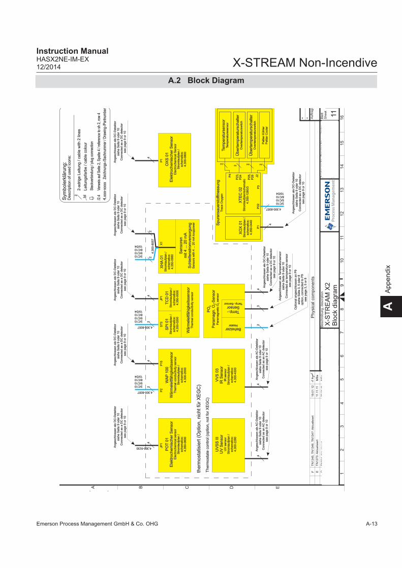
Emerson Process Management GmbH & Co. OHG A-13
X-STREAM Non-IncendiveInstruction ManualHASX2NE-IM-EX12/2014
AA
ppen
dix
A.2 Block Diagram
Phys
ical c
om
ponents
Spure
nsa
uers
toffm
ess
un
gT
race
Oxy
gen
4
P1
XO
X 0
1S
trom
laufp
lan /
sc
hem
atic
s:4.3
50-0
440
XT
EC
02
Str
om
laufp
lan/s
chem
atic
4.3
50-1
280/3
4.300-8057P22
P4
2J2
2P
25,
P26
Tem
pe
ratu
rsen
sor
Tem
pera
ture
senso
r
2
Pelti
er
Kühle
rP
elti
er
Coole
r
Üb
ert
em
pera
turs
chalte
rO
vert
em
pera
turs
witc
h
2P
23,
P24
Üb
ert
em
pera
turs
chalte
rO
vert
em
pera
turs
witc
h
P3
2-a
drige
Le
itun
g / c
able
with
2 li
nes
Sym
bo
lerk
läru
ng
:D
esc
riptio
n o
f u
sed
ico
ns:
Leitu
ng
sfa
rbe / c
able
colo
ur
bl
Ste
ckve
rbin
dung
/ pl
ug c
onne
ctio
n
/2.4
Ver
wei
s au
f Sei
te 2
, Spa
lte 4
/ re
fere
nce
to s
h 2,
row
4
4.x
xx-x
xxx
Zei
chnu
ngs-
/Sac
hnum
mer
/ D
raw
ing-
/Par
tnum
ber
2
PO
T 0
1E
lekt
roch
em
isch
er
Sen
sor
Ele
ctro
chem
ical s
enso
rS
trom
laufp
lan /
schem
atic
s:4.3
50-0
600
4
4.300-9150
WA
P 1
00
Wä
rme
leitf
ähig
keits
sen
sor
Therm
al c
onduct
ivity
senso
rS
trom
laufp
lan /
schem
atic
s:4.3
00-2
000
4
JP1
P15
2
P2
3/C105/C108/C1010/D4
4.300-8057
Wä
rme
leitf
ähig
keits
sen
sor
Therm
al c
onduct
ivity
senso
r
4
JP1
2
ST
3
3/C105/C108/C1010/D4
4.300-8057
Angesc
hlo
ssen a
ls D
C-D
ete
ktor
siehe S
eite
9 o
der
10
Connect
ed a
s a D
C d
ete
ctor
see p
age 9
or
10
Se
nso
ren
m
it 4 ... 2
0 m
A
Sch
leife
nst
rom
vers
org
ung
Senso
rs w
ith 4
... 2
0 m
A lo
oppow
er
2
X1
2
3/C105/C108/C1010/D4
4.3
00-8
057
XH
A 0
1S
trom
laufp
lan /
schem
atic
s:4.3
50-0
980
SP
I 0
1S
trom
laufp
lan /
schem
atic
s:4.3
50-0
200
TC
D 0
1S
trom
laufp
lan /
schem
atic
s:4.3
50-0
000
Angesc
hlo
ssen a
ls D
C-D
ete
ktor
siehe S
eite
9 o
der
10
Connect
ed a
s a D
C d
ete
ctor
see p
age 9
or
10
Angesc
hlo
ssen a
ls D
C-D
ete
ktor
siehe S
eite
9 o
der
10
Connect
ed a
s a D
C d
ete
ctor
see p
age 9
or
10
Angesc
hlo
ssen a
ls D
C-D
ete
ktor
siehe S
eite
9 o
der
10
Connect
ed a
s a D
C d
ete
ctor
see p
age 9
or
10
the
rmo
sta
tisie
rt (
Op
tion
, n
ich
t fü
r X
EG
C)
Th
erm
ost
ate
co
ntr
ol (
optio
n, n
ot fo
r X
EG
C)
UV
SS
III
UV
Sen
sor
UV
senso
rS
trom
laufp
lan /
schem
atic
s:4.3
00-2
280
VV
S 0
3IR
Se
nso
rIR
senso
rS
trom
laufp
lan /
schem
atic
s:4.3
00-4
300
4A
ngesc
hlo
ssen a
ls A
C-D
ete
ktor
siehe S
eite
9 o
der
10
Connect
ed a
s an A
C d
ete
ctor
see p
age 9
or
10
4A
ngesc
hlo
ssen a
ls A
C-D
ete
ktor
siehe S
eite
9 o
der
10
Connect
ed a
s an A
C d
ete
ctor
see p
age 9
or
10
OX
S 0
1E
lekt
roch
em
isch
er
Se
nso
rE
lect
roch
em
ical S
enso
rS
trom
laufp
lan /
sc
hem
atic
s:4.3
00-0
800
4
P1
Angesc
hlo
ssen a
ls D
C-D
ete
ktor
siehe S
eite
9 o
der
10
Connect
ed a
s a D
C d
ete
ctor
see p
age 9
or
10
3/C105/C108/C1010/D4
Angesc
hlo
ssen a
ls D
C-D
ete
ktor
siehe S
eite
9 o
der
10
Connect
ed a
s a D
C d
ete
ctor
see p
age 9
or
10
PO
2
Pa
ram
agn
. O
-Se
nso
r2
Para
magnetic
O s
enso
r2
43
2
Angesc
hlo
ssen a
ls D
C-D
ete
ktor
siehe S
eite
9 o
der
10
Connect
ed a
s a D
C d
ete
ctor
see p
age 9
or
10
Angesc
hlo
ssen a
ls T
em
pera
turs
enso
rsi
ehe S
eite
9 o
der
10
Connect
ed a
s te
mpera
ture
senso
rse
e p
age 9
or
10
Optio
nal a
ngesc
hlo
ssen a
n P
9si
ehe S
eite
3, 5 o
der
8optio
n, co
nnect
ed to P
9se
e p
age 3
, 5 o
r 8
BeheizerHeater
Temp.-Sensor
Temp.-Sensor
11
gg
E
Mic
roIn
de
xÄ
nd
eru
ng
, re
visi
on
Da
tum
Na
me
Be
arb
.
Ge
pr.
20
__
_D
atu
mN
am
e
Be
sch
reib
un
g,
de
scrip
tion
Ze
ich
nu
ng
-Nr.
: D
raw
ing
-No
.:In
de
x
Ide
nt-
Nr.
:
Bla
ttS
he
et
Au
ftra
gs
+=
DCBA
12
34
56
78
91
011
12
13
14
15
16
4.3
00-5
158/4
07
02.1
0.
Walth
er
Sch
mid
tX
-ST
RE
AM
X2
Blo
ck d
iagra
m03.1
0.
BN
eue G
ehäuse
variante
n h
inzu
12.0
8.0
9M
Ba
CT
N846: T
race
Mois
ture
hin
zu
11.1
1.1
0M
Ba
DT
N934: A
ktualis
iert
20.0
1.1
1M
Ba
F
EM
Ba
11.1
1.1
1T
N1273: A
ktualis
iert
F19.0
1.1
2T
N1345, T
N1346, T
N1347: A
ktualis
iert

Emerson Process Management GmbH & Co. OHGA-14
X-STREAM Non-IncendiveInstruction Manual
HASX2NE-IM-EX12/2014
Because of legal regulations and for the safety of Emerson Process Management employees and operating equipment, we need this "Declaration of Decontamination", signed by an authorized person, prior to processing your order. Ensure to include it with the shipping documents, or (re-commended) attach it to the outside of the packaging.
Instrument detailsAnalyzer model
Serial no.
Process detailsTemperature
Pressure
Please check where applicable, include safety data sheet and, if necessary, special handling instructions!
The medium was used for
Medium and concentration CAS No. toxic harmful corrosive fl amma-
ble other1) harmless
Process
Process cleaning
Cleaning ofreturned parts
1) e.g. explosive, radioactive, environmentally hazardous, of biological risk, etc.
Declaration and Sender DataWe hereby declare that the retumed parts have been carefully cleaned. To the best of our knowledge they are free from any residues in dangerous quantities.Company Contact Person / Function
Address
Phone
Location, Date Signature
A.3 Declaration of Decontamination
A.3 Declaration of Decontamination

Emerson Process Management GmbH & Co. OHG A-15
AA
ppen
dix
X-STREAM Non-IncendiveInstruction ManualHASX2NE-IM-EX12/2014
A.7 Assignment of Plugs and Terminals
A.7 Assignment of Plugs and TerminalsXSTA: Standard strip with standard and optional signals XSTD: Optional strips with
7 Dig Inputs and 9 Dig Outputs each
Signal Terminals StripsService Port Connector - Serial RS 232 interface
Pin9876
Pin54321
Pin no. RS 232
1 Common2 RXD3 TXD4 not used5 Common6 not used7 not used8 not used9 not used
Ethernet connector for Modbus
Pin 1 Pin 8
Pin no. Signal
1 TX+2 TX-3 RX+6 RX-
other not used
Assignment of serial interface terminals
*) See table below **) Configuration of relay output terminals as per standard factory setting (NAMUR status signals)
PinSignal
P3.1
Input 1/8***)
P3.2
Input 2/9P
3.3Input 3/10
P3.4
Input 4/11P
3.5Input 5/12
P3.6
Input 6/13P
3.7Input 7/14
P3.8
GN
D for Inputs 1-7/8-14
P3.9
not usedP
3.10O
utput 5/14, NC
P3.11
Output 5/14, N
OP
3.12O
utput 5/14, CO
MP
4.1O
utput 6/15, NC
P4.2
Output 6/15, N
OP
4.3O
utput 6/15, CO
MP
4.4O
utput 7/16, NC
P4.5
Output 7/16, N
OP
4.6O
utput 7/16, CO
MP
4.7O
utput 8/17, NC
P4.8
Output 8/17, N
OP
4.9O
utput 8/17, CO
MP
4.10O
utput 9/18, NC
P4.11
Output 9/18, N
OP
4.12O
utput 9/18, CO
MP
2.1O
utput 10/19, NC
P2.2
Output 10/19, N
OP
2.3O
utput 10/19, CO
MP
2.4O
utput 11/20, NC
P2.5
Output 11/20, N
OP
2.6O
utput 11/20, CO
MP
2.6O
utput 12/21, NC
P2.8
Output 12/21, N
OP
2.9O
utput 12/21, CO
MP
2.10O
utput 13/22, NC
P2.11
Output 13/22, N
OP
2.12O
utput 13/22, CO
M
Digital InputsDigital Outputs
***) 1st /2nd no. identifies inputs/outputs on the 1st /2nd expansion board
Power terminals
L
PE
N
Power cord entry
L= LineN= NeutralPE= Protective Earth
Note!Line and neutral terminals with built-in fuse holders
PinSignal
P2.1
Channel 1, (+) 4 (0) - 20 m
AP
2.2C
hannel 1, GN
DP
2.3C
hannel 2, (+) 4 (0) - 20 mA
P2.4
Channel 2, G
ND
P2.5
Channel 3, (+) 4 (0) - 20 m
AP
2.6C
hannel 3, GN
DP
2.7C
hannel 4, (+) 4 (0) - 20 mA
P2.8
Channel 4, G
ND
P2.9
Channel 5, (+) 4 (0) - 20 m
AP
2.10C
hannel 5, GN
DP
2.11not used
P2.12
not usedP
3.1not used
P3.2
not usedP
3.3O
utput 1 (Failure), NC
P3.4
Output 1 (Failure), N
OP
3.5O
utput 1 (Failure), CO
MP
3.6O
utput 2 (Maintenance R
equest), NC
P3.7
Output 2 (M
aintenance Request), N
OP
3.8O
utput 2 (Maintenance R
equest), CO
MP
3.9O
utput 3 (Out of S
pec), NC
P3.10
Output 3 (O
ut of Spec), N
OP
3.11O
utput 3 (Out of S
pec), CO
MP
3.12O
utput 4 (Function check), NC
P4.1
Output 4 (Function check), N
OP
4.2O
utput 4 (Function check), CO
MP
4.3not used
P4.4
P4.5
P4.6
P4.7
P4.8
P4.9
P4.10
P4.11
P4.12
Relay Outputs**) Analog OutputsSerial Interface*)
Terminal MOD 485/2 wire
MOD 485/4 wire RS 232
P4.4 SER1 Common Common CommonP4.5 SER2 not used not used RXDP4.6 SER3 not used not used TXDP4.7 SER4 not used RXD1(+) not usedP4.8 SER5 D1(+) TXD1(+) CommonP4.9 SER6 not used not used not used
P4.10 7 not used not used not usedP4.11 8 not used RXD0(-) not usedP4.12 9 D0(-) TXD0(-) not used

X-STREAM Non-Incendive
Emerson Process Management GmbH & Co. OHGA-16
Instruction ManualHASX2NE-IM-EX
12/2014

Emerson Process Management GmbH & Co. OHG
X-STREAM Non-IncendiveInstruction ManualHASX2NE-IM-EX12/2014
Emerson Process Management GmbH & Co. OHG
X-STREAM Non-IncendiveInstruction Manual
HASX2NE-IM-EX12/2014
http://twitter.com/raihome
http://www.analyticexpert.com
Rosemount Analytical Process Gas Analyzer Center of Excellence Emerson Process Management GmbH & Co. OHGIndustriestrasse 163594 HasselrothGermanyT +49 6055 884 0F +49 6055 884 209
Rosemount Analytical Inc.Gas Analyzer Service Center6565P Davis Industrial ParkwaySolon, OH 44139 USAT +1 440.914.1261Toll Free in US and Canada 800.433.6076F +1 440.914.1262e-mail: [email protected] Response Center 800.654.7768
EUROPE
Emerson Process ManagementShared Services LimitedHeath PlaceBognor RegisWest Sussex PO22 9SHEnglandT +44 1243 863121F +44 1243 845354
LATIN AMERICA
Emerson Process Management Rosemount Analytical11100 Brittmoore Park DriveHouston, TX 77041 USAT +1 713.467.6000F +1 713.827.3328
ASIA-PACIFIC
Emerson Process ManagementAsia Pacific Private Limited1 Pandan CrescentSingapore 128461Republic of SingaporeT +65 6 777 8211F +65 6 777 0947e-mail: [email protected]
MIDDLE EAST AND AFRICA
Emerson Process ManagementEmerson FZEP.O. Box 17033Jebel Ali Free ZoneDubai, United Arab EmiratesT +971 4 811 8100F +971 4 886 5465
© 2014 Emerson Process Management GmbH & Co. OHG