Embed Size (px)
Citation preview

G3_LED 12/18 page 1 of 4
Ordering guide Example: G3-5-32L-1000-NW-G2-UNV-MGY-QDM
Prefix
G3
Controls DistributionLED Count
Drive Current
Color Temp - Generation Voltage Finish Options
G3 G3 LED Standard luminaire
- Standard Luminaire
DD 0-10V Dimming5
MR Motion Response 1,2
MRCP Motion Response 1,2 Factory Programming
RC Wireless system,3
5 Type 5 Symmetrical
5DL Type 5 Diffuse Lens
3 Type 3 Asymmetrical
1R Type 1R Rectangular
CD Concentrated Downlight
16L 16 LEDs
400 400 mA
700 700 mA
1000 1000 mA
NW-G2 Neutral White 4000K, 70 CRI Generation 2
CW-G2 Cool White 5700K, 70 CRI Generation 2
WW-G2 Warm White 3000K, 70 CRI Generation 2
120
208
240
277
347
480
UNV (120-277V)
HVU (347-480V)
MGY Medium Gray (standard)
BZ Bronze
BK Black
WH White
F1 Single Fuse (120, 277, 347V)4
F2 Double Fuse (208, 240, 277V)4
F3 Double Fuse Canadian double pull (208, 240, 480V)4
PCB Photocontrol Button4
QDM Driver Quick Disconnect Module
BXS Bird Excluding Shroud (factory installed, for Standard Surface Mount Only)
32L 32 LEDs
600 600 mA
800 800 mA
1000 1000 mA
1. Only available in 120 through 277V.2. See page 3 for more information on motion
sensor provided.3. G3-RC luminaires must be configured and quoted by
factory prior to ordering. G3-RC luminaires rated to 40°C.4. Specify actual input voltage.
5. Luminaire includes 0-10V dimming wires for dimming controls by others.
6. ‘BX’ bird excluding shroud is for ‘PB-NP’ pendant mount only. Field installed and requires 12” minimum pendant length. Pendant by others.
Accessories (order separately)
FSIR-100
MR hand held programmer (For use with 'MR' motion response when field programming is required). If desired, only one is needed per job.
BX-16L BX-32L
Bird Excluding Shroud (field installed, for use with PB-NP pendant mount). Choose for either 1 array 16L 16 LEDs or 2 array 32L 32 LEDs.6
PB-NP
Balanced J-box for Pendant Mount (field installed, Medium Gray paint).6
Garage & Canopy
G3
Garage & Canopy
Project:
Location:
Cat.No:
Type:
Lamps: Qty:
Notes:
Gardco LED parking garage luminaire G3 combines excellent performance with value, providing one of the most energy efficient lighting solutions for the energy and budget conscious. A complete selection of optical systems are available, including a concentrated downlight for use at entrances or at higher mounting heights. G3 luminaires are available with dimming, as well as motion response technology to expand potential energy savings. The G3 is also available with wireless lighting system.

G3_LED 12/18 page 2 of 4
LED Wattage and Lumen Values Standard G3 Luminaires
Note: Due to rapid and continuous advances in LED technology, LED luminaire data is subject to change without notice and at the discretion of Signify. Lumen output by optic type will vary slightly. See IES files when available. All technical data is subject to change.Contact [email protected] for additional tests or information, including higher lumen output test results (available upon request as an ETO).
Order CodeLED Qty
System Current
(mA)
Color Temp
(K)
Ave System Watts
(W)
5 5DL 3 1R CD
Lumen Output
Efficacy (lm/W)
Lumen Output
Efficacy (lm/W)
Lumen Output
Efficacy (lm/W)
Lumen Output
Efficacy (lm/W)
Lumen Output
Efficacy (lm/W)
G3-16L-400-NW-G2 16 400 4000 25 2732 111 2260 92 2898 118 2794 114 2895 118
G3-16L-700-NW-G2 16 700 4000 36 4413 123 3651 101 4682 130 4513 125 4676 130
G3-16L-1000-NW-G2 16 1000 4000 57 5843 103 4834 85 6199 109 5975 105 6191 109
G3-32L-600-NW-G2 32 600 4000 64 7895 124 6532 103 8376 132 8073 127 8365 132
G3-32L-800-NW-G2 32 800 4000 85 10020 117 8290 97 10630 125 10246 120 10617 124
G3-32L-1000-NW-G2 32 1000 4000 107 11850 111 9804 92 12572 118 12118 114 12556 118
Dimensions - G3 Standard (EZ hanger plate mount shown)
2 LED Array Top View
10.68”(27.12 cm)
3.20”(8.13 cm)
1.18”(2.99 cm)
15.59”(39.6 cm)
3.2”(8.1 cm)
1.18”(2.99 cm)
2 LED Array Side View
1 LED Array Top View
1 LED Array Side View
Approximate luminaire Weight: 9.75 Lbs (4.42 Kg)
Approximate luminaire Weight: 12.5 Lbs (5.67 Kg)
15.59”(39.6 cm)
13.31”(33.8 cm)
10.68”(27.12 cm)
13.31”(33.8 cm)
Dimensions - G3-RC Wireless
standard mounting mounts to standard 4” square or octagonal j-boxes
2 LED Array Top View
10.68”(27.12 cm)
13.31”(33.8 cm)
15.59”(39.6 cm)
13.31”(33.8 cm)
1 LED Array Top View
1 & 2 LED Array Front View
17.9”(45.46 cm)
Approximate luminaire Weight: 11.25 Lbs (5.1 Kg)
Approximate luminaire Weight: 13.07 Lbs (5.92 Kg)
G3 LED parking garage & canopy luminaire
Garage & Canopy
G3_LED 12/18 page 3 of 4
Motion Response Luminaires
Programmable Motion Response
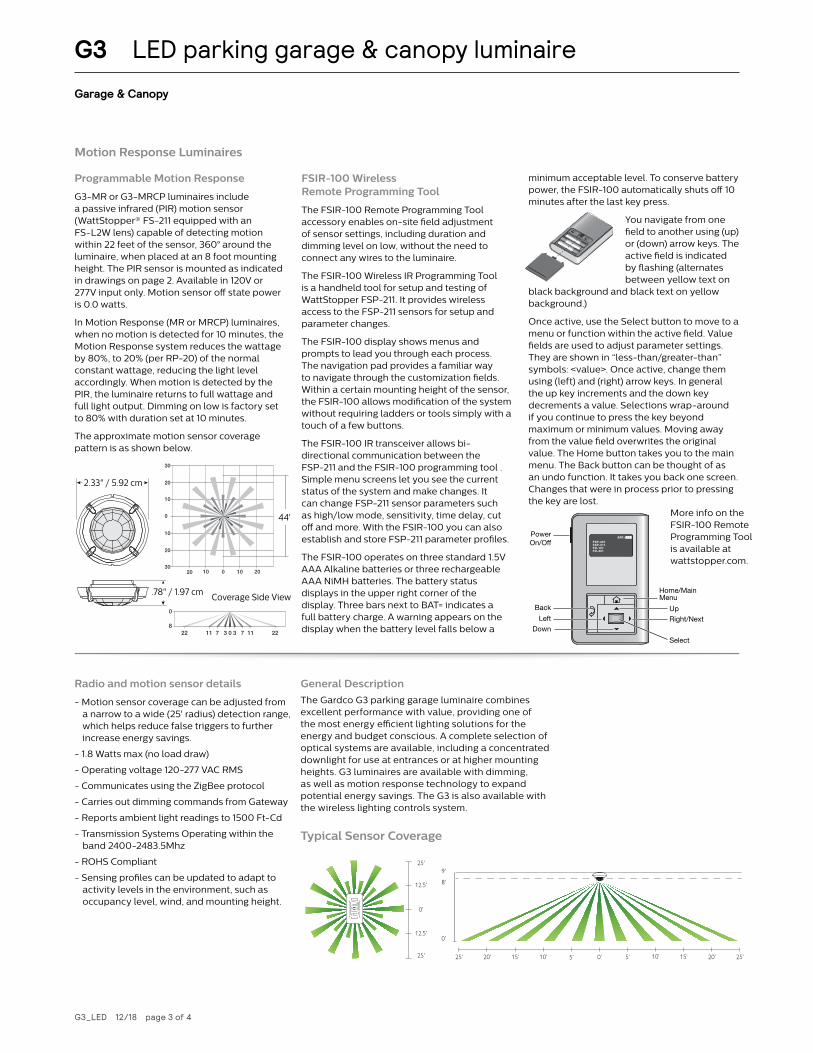
G3-MR or G3-MRCP luminaires include a passive infrared (PIR) motion sensor (WattStopper® FS-211 equipped with an FS-L2W lens) capable of detecting motion within 22 feet of the sensor, 360° around the luminaire, when placed at an 8 foot mounting height. The PIR sensor is mounted as indicated in drawings on page 2. Available in 120V or 277V input only. Motion sensor off state power is 0.0 watts.
In Motion Response (MR or MRCP) luminaires, when no motion is detected for 10 minutes, the Motion Response system reduces the wattage by 80%, to 20% (per RP-20) of the normal constant wattage, reducing the light level accordingly. When motion is detected by the PIR, the luminaire returns to full wattage and full light output. Dimming on low is factory set to 80% with duration set at 10 minutes.
The approximate motion sensor coverage pattern is as shown below.
FSIR-100 Wireless Remote Programming Tool
The FSIR-100 Remote Programming Tool accessory enables on-site field adjustment of sensor settings, including duration and dimming level on low, without the need to connect any wires to the luminaire.
The FSIR-100 Wireless IR Programming Tool is a handheld tool for setup and testing of WattStopper FSP-211. It provides wireless access to the FSP-211 sensors for setup and parameter changes.
The FSIR-100 display shows menus and prompts to lead you through each process. The navigation pad provides a familiar way to navigate through the customization fields.Within a certain mounting height of the sensor, the FSIR-100 allows modification of the system without requiring ladders or tools simply with a touch of a few buttons.
The FSIR-100 IR transceiver allows bi-directional communication between the FSP-211 and the FSIR-100 programming tool . Simple menu screens let you see the current status of the system and make changes. It can change FSP-211 sensor parameters such as high/low mode, sensitivity, time delay, cut off and more. With the FSIR-100 you can also establish and store FSP-211 parameter profiles.
The FSIR-100 operates on three standard 1.5V AAA Alkaline batteries or three rechargeable AAA NiMH batteries. The battery status displays in the upper right corner of the display. Three bars next to BAT= indicates a full battery charge. A warning appears on the display when the battery level falls below a
minimum acceptable level. To conserve battery power, the FSIR-100 automatically shuts off 10 minutes after the last key press.
You navigate from one field to another using (up) or (down) arrow keys. The active field is indicated by flashing (alternates between yellow text on
black background and black text on yellow background.)
Once active, use the Select button to move to a menu or function within the active field. Value fields are used to adjust parameter settings. They are shown in “less-than/greater-than” symbols: <value>. Once active, change them using (left) and (right) arrow keys. In general the up key increments and the down key decrements a value. Selections wrap-around if you continue to press the key beyond maximum or minimum values. Moving away from the value field overwrites the original value. The Home button takes you to the main menu. The Back button can be thought of as an undo function. It takes you back one screen. Changes that were in process prior to pressing the key are lost.
2.33”59.2mm
0.78”19.7mm
FSP-L4: 360° CoverageThe FSP-L4 is designed for mounting at heights between 30’ to 40’ . Its coverage area can be up to 60’ in diameter when mounted at 40’ .
COVERAGE PATTERN
Density and range of the coverage pattern is determined by the type of lens and mounting height .
FSP-L2: 360° CoverageThe FSP-L2 lens provides a 44’ diameter coverage area when mounted at a height of 8’ .
FSP‑L3 High Densi ty/Reduced Range Lens
FSP‑L2 Low Densi ty/Wide Range Lens
03 9636912 12
10
20
0
15
5
151820 15 18 20
20 10 0 10 20
0
20
10
10
20
40 ft
2.33”59.2mm
0.78”19.7mm
30
30
20
10
10
20
0
8
0
10 0
0 33 77 1111 2222
10 2020
44 ft
FSP‑L4 40 Foot High Bay Lens
0 6 12 3061230 20 20
0
10
20
30
40
0 3 6 12 2730
36122730
20 20
036
36
12
27
30
12
27
20
20
60 ft
3.2”81.3mm
0.93”23.6mm
FSP-L3: 360° CoverageThe FSP-L3 has a high density lens that covers a 40’ diameter area at a height of 20’ .
WIRING A SINGLE SENSOR
Non-DimmingDriver
LIN
EN
EU
TRA
L
NEUTRAL
LOAD
* GROUND
Occupancy Sensor
5E4
800.879.8585www.wattstopper.com
1519
5r1
LOA
D
LIN
E
NEU
T(v
iole
t)
(gre
y)
18-20 AWG Solid CU Wire Only
230 VAC, 50 Hz1200W max ballast
FSP-211
GRN
D
DIM
-
DIM
+
14-18 AWG Solid CU Wire Only
High/Low PIR
Non-Dimming Driver
DimmingDriver
LIN
EN
EU
TRA
L
NEUTRAL
*GROUND
GRAY (-)
VIOLET (+)
LOAD
Occupancy Sensor
5E4
800.879.8585www.wattstopper.com
1519
5r1
LOA
D
LIN
E
NEU
T(v
iole
t)
(gre
y)
18-20 AWG Solid CU Wire Only
230 VAC, 50 Hz1200W max ballast
FSP-211
GRN
D
DIM
-
DIM
+
14-18 AWG Solid CU Wire Only
High/Low PIR
Dimming Driver
1 . Determine an appropriate mounting location inside the light fixture . Allow a minimum distance of 0 .2” (5 .1mm) from the wiring end of the sensor to the wall of the fixture .
2 . Drill a hole 1 .30” (33 .0mm) in diameter through the sheet metal in the bottom of the fixture .
3 . Add the rubber gasket to the threaded collar, and install the sensor face down, parallel to the mounting surface . Ensure the rubber gasket touches the inside surface of the fixture . Install the plastic nut securely against the fixture to a torque of 25-30 in-lbs to ensure IP rating is maintained .
4 . Align the locking features between the sensor and lens module and push the lens module forward until the o-ring seals firmly . Turn the lens module clockwise to ensure it locks in place .
5 . Connect load and supply wires as shown in wiring diagram .6 . Restore power from the circuit breaker .
CAUTION TURN THE POWER OFF AT THE CIRCUIT BREAKER
BEFORE INSTALLING THE SENSOR.
TighteningNut
TighteningNut Fixture
Wall
Lens Assembly
FSP-211
Outside Fixture Wall
Inside FixtureWall
RubberGasket
RubberGasket
Note: The Outside Fixture Wall thickness should be no greater than 0 .125” (3 .18mm) for optimal sensor mounting and security .
* Note: The FSP-211 must be grounded to ensure signal integrity, not for safety ground .
Outdoor Use at the exposed Sensor Collar part only when installed at the specific location per Installation
Instructions with a Listed Outdoor Enclosure.
INSTALLATION
30
30
20
10
10
20
0
8
0
10 0
0 33 77 1111 2222
10 2020
44 ft
Coverage Top View
Coverage Top View
Coverage Top View
Coverage Side View
Coverage Side View
Coverage Side View
2.33" / 5.92 cm
.78" / 1.97 cm
2.33”59.2mm
0.78”19.7mm
FSP-L4: 360° CoverageThe FSP-L4 is designed for mounting at heights between 30’ to 40’ . Its coverage area can be up to 60’ in diameter when mounted at 40’ .
COVERAGE PATTERN
Density and range of the coverage pattern is determined by the type of lens and mounting height .
FSP-L2: 360° CoverageThe FSP-L2 lens provides a 44’ diameter coverage area when mounted at a height of 8’ .
FSP‑L3 High Densi ty/Reduced Range Lens
FSP‑L2 Low Densi ty/Wide Range Lens
03 9636912 12
10
20
0
15
5
151820 15 18 20
20 10 0 10 20
0
20
10
10
20
40 ft
2.33”59.2mm
0.78”19.7mm
30
30
20
10
10
20
0
8
0
10 0
0 33 77 1111 2222
10 2020
44 ft
FSP‑L4 40 Foot High Bay Lens
0 6 12 3061230 20 20
0
10
20
30
40
0 3 6 12 2730
36122730
20 20
036
36
12
27
30
12
27
20
20
60 ft
3.2”81.3mm
0.93”23.6mm
FSP-L3: 360° CoverageThe FSP-L3 has a high density lens that covers a 40’ diameter area at a height of 20’ .
WIRING A SINGLE SENSOR
Non-DimmingDriver
LIN
EN
EU
TRA
L
NEUTRAL
LOAD
* GROUND
Occupancy Sensor
5E4
800.879.8585www.wattstopper.com
1519
5r1
LOA
D
LIN
E
NEU
T(v
iole
t)
(gre
y)
18-20 AWG Solid CU Wire Only
230 VAC, 50 Hz1200W max ballast
FSP-211
GRN
D
DIM
-
DIM
+
14-18 AWG Solid CU Wire Only
High/Low PIR
Non-Dimming Driver
DimmingDriver
LIN
EN
EU
TRA
L
NEUTRAL
*GROUND
GRAY (-)
VIOLET (+)
LOAD
Occupancy Sensor
5E4
800.879.8585www.wattstopper.com
1519
5r1
LOA
D
LIN
E
NEU
T(v
iole
t)
(gre
y)
18-20 AWG Solid CU Wire Only
230 VAC, 50 Hz1200W max ballast
FSP-211
GRN
D
DIM
-
DIM
+
14-18 AWG Solid CU Wire Only
High/Low PIR
Dimming Driver
1 . Determine an appropriate mounting location inside the light fixture . Allow a minimum distance of 0 .2” (5 .1mm) from the wiring end of the sensor to the wall of the fixture .
2 . Drill a hole 1 .30” (33 .0mm) in diameter through the sheet metal in the bottom of the fixture .
3 . Add the rubber gasket to the threaded collar, and install the sensor face down, parallel to the mounting surface . Ensure the rubber gasket touches the inside surface of the fixture . Install the plastic nut securely against the fixture to a torque of 25-30 in-lbs to ensure IP rating is maintained .
4 . Align the locking features between the sensor and lens module and push the lens module forward until the o-ring seals firmly . Turn the lens module clockwise to ensure it locks in place .
5 . Connect load and supply wires as shown in wiring diagram .6 . Restore power from the circuit breaker .
CAUTION TURN THE POWER OFF AT THE CIRCUIT BREAKER
BEFORE INSTALLING THE SENSOR.
TighteningNut
TighteningNut Fixture
Wall
Lens Assembly
FSP-211
Outside Fixture Wall
Inside FixtureWall
RubberGasket
RubberGasket
Note: The Outside Fixture Wall thickness should be no greater than 0 .125” (3 .18mm) for optimal sensor mounting and security .
* Note: The FSP-211 must be grounded to ensure signal integrity, not for safety ground .
Outdoor Use at the exposed Sensor Collar part only when installed at the specific location per Installation
Instructions with a Listed Outdoor Enclosure.
INSTALLATION
30
30
20
10
10
20
0
8
0
10 0
0 33 77 1111 2222
10 2020
44 ft
Coverage Top View
Coverage Top View
Coverage Top View
Coverage Side View
Coverage Side View
Coverage Side View
Coverage Side View
44'
FSP-211 COMMISIONING
The commissioning process establishes the appropriate param-eters for the FSP-211 operation . This is done through the use of the FSIR-100 commissioning tool . If no commissioning steps are taken, the sensor will use its default parameter values .
USING THE FSIR-100 PROGRAMMING TOOL
The FSIR-100 Wireless IR Programming Tool is a handheld tool for setup and testing of WattStopper FSP-211 .It provides wireless access to the FSP-211 sensors for setup and parameter changes .
The FSIR-100 display shows menus and prompts to lead you through each process . The navigation pad provides a familiar way to navigate through the customization fields .
Within a certain mounting height of the sensor, the FSIR-100 allows modification of the system without requiring ladders or tools; simply with a touch of a few buttons .
OPERATION
The FSIR-100 IR transceiver allows bi-directional communication between the FSP-211 and the FSIR-100 programming tool . Simple menu screens let you see the current status of the system and make changes . It can change FSP-211 sensor parameters such as high/low mode, sensitivity, time delay, cut off and more . With the FSIR-100 you can also establish and store FSP-211 parameter profiles .
BATTERIES
The FSIR-100 operates on three standard 1 .5V AAA Alkaline batteries or three rechargeable AAA NiMH batteries . The battery status displays in the upper right corner of the display . Three bars next to BAT= indicates a full battery charge . A warning appears on the display when the battery level falls below a minimum acceptable level . To conserve battery power, the FSIR-100 automatically shuts off 10 minutes after the last key press .
NAVIGATION
You navigate from one field to another using (up) or (down) arrow keys . The active field is indicated by flashing (alternates between yellow text on black background and black text on yellow background .
Once active, use the Select button to move to a menu or function within the active field . Value fields are used to adjust parameter settings . They are shown in “less-than/greater-than” symbols: <value> . Once active, change them using(left) and(right) arrow keys . In general the up key increments and the down key decrements a value . Selections wrap-around if you continue to press the key beyond maximum or minimum values . Moving away from the value field overwrites the original value . The Home button takes you to the main menu . The Back button can be thought of as an undo function . It takes you back one screen . Changes that were in process prior to pressing the key are lost .
FSP-201FSP-211FD-101FD-301
Home/MainMenu
Up
Select
DownRight/NextLeft
Back
PowerOn/Off
BAT=
IR COMMUNICATION
IR communication can be affected by the mounting height of the sensor and high ambient lighting such as direct daylight of electric light such as floodlights, and some halogen, fluorescent lamps, LED’s .
When trying to communicate with the FSP-211, be sure to be positioned under the sensor without any obstructions . Every time the programming tool establishes communication with the FSP-211, the controlled load will cycle .
• If communication is not successful, (if possible) move closer to the sensor .
• If still not successful, there may be too much IR interference from other sources . Programing the unit at night when there is no daylight available may be the only way to communicate with the sensor .
15'-30'
* Distance may vary depending on the lighting environment
Typical Sensor Coverage
0’
0’
8’
9’
10’5’ 20’ 25’15’10’ 5’20’25’ 15’
12.5’
0’
25’
12.5’
25’0’
0’
8’
9’
10’5’ 20’ 25’15’10’ 5’20’25’ 15’
12.5’
0’
25’
12.5’
25’
Radio and motion sensor details
- Motion sensor coverage can be adjusted from a narrow to a wide (25' radius) detection range, which helps reduce false triggers to further increase energy savings.
- 1.8 Watts max (no load draw)
- Operating voltage 120-277 VAC RMS
- Communicates using the ZigBee protocol
- Carries out dimming commands from Gateway
- Reports ambient light readings to 1500 Ft-Cd
- Transmission Systems Operating within the band 2400-2483.5Mhz
- ROHS Compliant
- Sensing profiles can be updated to adapt to activity levels in the environment, such as occupancy level, wind, and mounting height.
General Description
The Gardco G3 parking garage luminaire combines excellent performance with value, providing one of the most energy efficient lighting solutions for the energy and budget conscious. A complete selection of optical systems are available, including a concentrated downlight for use at entrances or at higher mounting heights. G3 luminaires are available with dimming, as well as motion response technology to expand potential energy savings. The G3 is also available with the wireless lighting controls system.
More info on the FSIR-100 Remote Programming Tool is available at wattstopper.com.
G3 LED parking garage & canopy luminaire
Garage & Canopy

Specifications
Housing
Modular die-cast driver housing with one to two die-cast LED array heatsink assemblies.
IP Rating
IP66 rated driver housing with dedicated IP66 rated LED modules. Motion response luminaire are rated IP65.
Electrical
Driver efficiency (>90% standard). 120-480V available (restrictions apply). Temp range: -40°C (-40°F) to +40°C (+104°F). Open/short circuit protection. Optional 0-10V dimming to 10% power. RoHS compliant. Surge protector standard and is in accordance with IEEE / ANSI C62.41.2 guidelines, with a surge current rating of 10kA.
Mounting
A die formed 14 ga. galvanized steel plate is supplied for mounting to a recessed, surface, or rigid pendant hung 4” (10.16 cm) j-box (standard j-box and rigid pendant by others). An integral hanger tab on the plate supports the luminaire during wiring. All pendants, including rigid pendants and swivel pendants (utilized with the balanced j-box PB-NP option), are supplied by others.
Caution: Gardco is not responsible for failure of mounting components supplied by others. Proper care should be exercised in mounting component selection to insure adequate luminaire support, given luminaire weight, vibration potential and thermal conditions present in the application. If luminaires are supported solely by screws into a composite j-box, additional support directly to structure is recommended. Failure to properly support the luminaire may cause damage or injury, for which Gardco is not responsible.
Controls
Motion Response luminaires (MR and MRCP) include a passive infrared (PIR) motion sensor (WattStopper FSP-211 equipped with an FS-L2W lens) capable of detecting motion within 22 feet of the sensor, 360° around the luminaire, when placed at an 8-12 foot mounting height. Available in 120V to 277V input only. Motion sensor off state power is 1 watt. In Motion Response luminaires, when no motion is detected for 10 minutes, the Motion Response system reduces the wattage by 80%, to 20% of the normal constant wattage per RP-20, reducing the light level accordingly. When motion is detected by the PIR, the luminaire returns to full wattage and full light output. Includes a daylight sensor which enables daylight harvesting. Wireless Remote Programming tool available (FSIR-100) for field programming (ordered separately).
Wireless system (RC) also available, which combine the intelligence of motion and daylight sensing with wireless technology, allowing you to connect with your lighting system via the web.
LED Module
LED array of 16 or 32 high power LEDs. Metal core printed circuit board. LEDs tested by ISO 17025-2005 accredited lab in accordance with IESNA LM-80 guidelines extrapolations in accordance with IESNA TM-21. IP66 sealed light engines designed and tested to rating IK10 in accordance with European standard EN 62262 (equivalent of international standard IEC 62262 2002). RoHS compliant. Color temperatures per ANSI/NEMA bin Warm White 3000 Kelvin nominal (3045 +/- 175K), Neutral White 4000 Kelvin nominal (3985 +/- 250K), or Cool White 5700 Kelvin nominal (5667 +/- 355K). CRI 70 min.
LED Thermal Management
The housing design provides thermal radiation fins in the upper housing to provide the excellent thermal management critical to long LED system life.
Vibration Resistance
When 3G vibration rating that conforms to the standards set forth by ANSI C136.31 is required, contact Quotations for modified bracket (available upon request as an ETO).
Optical Systems
Type 5 symmetrical, Type 3 asymmetrical, Type 1R rectangular and CD concentrated downlight. Type 1R is designed to meet IES minimums with one luminaire per parking bay compared to the typical two per bay. Diffuse lens is available with Type 5 to limit perceived luminaire brightness, resulting in reduced performance.
Energy saving benefits
System efficacy up to 132 lms/W with significant energy savings over HID systems less controls. Optional MR motion response sensor provides added energy savings during unoccupied periods and works as a ‘Smart Luminaire’ requiring no added wiring or commissioning at install.
Listings
cULus Listed for Canada and USA. Entire luminaire is rated for operation in ambient temperatures from -40° (-40°F) to +40°C (+104°F). G3 luminaires are DesignLights Consortium qualified when ordered with CW or NW LED color temperature. WW option 400mA-800mA DesignLights Consortium qualified; WW option 1000mA does not meet DLC.
Finish
Each luminaire receives a fade and abrasion resistant, electrostatically applied, thermally cured, triglycidal isocyanurate (TGIC) textured polyester powdercoat finish. Standard finish of all diecast assemblies shall be Medium Gray paint.
Warranty
5 year limited warranty. See signify.com/outdoorluminaires for complete details and exclusions.
Predicted Lumen Depreciation Data
Ambient Temperature °C
System Current
Calculated L70hrs 1,2
L70 per TM21 2,3
Lumen Maintenance @ 60,000hrs
25 °C 1000 mA >100,000 >60,000 93%
1. Predicted performance derived from LED manufacturer's data and engineering design estimates, based on IESNA LM-80 methodology. Actual experience may vary due to field application conditions.
2. L70 is the predicted time when LED performance depreciates to 70% of initial lumen output.3. Calculated per IESNA TM 21-11. Published L70 hours limited to 6 times actual LED test hours.
© 2019 Signify Holding B.V. All rights reserved. Signify reserves the right to make changes in specifications and/or to discontinue any product at any time without notice or obligation and will not be liable for any consequences resulting from the use of this publication.
G3_LED 12/18 page 4 of 4
Signify, North America Corp., 200 Franklin Square Drive, Somerset, NJ 08873 Tel. 855-486-2216
Signify, Canada Ltd., 281 Hillmount Rd, Markham, ON, Canada L6C 2S3 Tel. 800-668-9008
G3 LED parking garage & canopy luminaire
Garage & Canopy
www.gardcolighting.com