Embed Size (px)
Citation preview

Formal Aspects of VLSI Research Group
University of Utah� Department of Computer Science
HOP� A Formal Model for Synchronous Circuits using Commu�
nicating Fundamental Mode Symbolic Automata�
GANESH GOPALAKRISHNAN �ganesh�cs�utah�edu�
University of Utah
Dept� of Computer Science
Salt Lake City� Utah �����
Keywords� Formal Hardware Speci�cation� Veri�cation� Synchronous VLSI Design� Symbolic Automaton
Models
Abstract� We study synchronous digital circuits in an abstract setting� A circuit is viewed as a collection of
modules connected through their boundary ports� where each port assumes a �xed direction �input or output�
over one cycle of operation� and can change directions across cycles� No distinction is made between clock
inputs and non�clock inputs� A cycle of operation consists of the application of a set of inputs followed by
the stabilization of the module state before the next inputs are applied �i�e� fundamental mode operation is
assumed�� The states and inputs of a module are modeled symbolically� in a functional notation� This enables
us to study not only �nite�state controllers� but also large data paths� possibly with unbounded amounts
of state� We present the abstract syntax for modules� well�formedness checks on the syntax� the formal
semantics in terms of the denotation of a module� and the rule for composing two modules interconnected
and operating in parallel� embodied in the operator par� It is shown that par preserves well�formedness� and
denotes conjunction� These results are applicable to virtually every kind of synchronous circuit �e�g� VLSI
circuits that employ single or multiphase clocks� circuits that employ switch or gate logic structures� circuits
that employ uni� or bi�directional ports� etc��� thanks to the small number of assumptions upon which the
HOP model is set up�
� Introduction
Synchronous digital circuits are� perhaps� one of the most widely studied forms of hard�
ware� The most common de�nition of a synchronous digital system is that it is globally
clocked� This de�nition is often not directly applicable to all real�world synchronous hard�
ware systems because some real�world synchronous systems employ polyphase clocks� and
their submodules use di�erent subsets of the set of global clock phases� An obvious gener�
alization of the above de�nition of synchronous systems is� �a system with a logical clock
that acts as the global time reference� and to which all the actual clock phases are aligned��
Though mathematically accurate� this view of synchronous systems violates the principle
�Supported in part by NSF Awards MIP ����� and ��� � � printed �������

� GANESH GOPALAKRISHNAN
of modularity� a hardware module cannot be understood purely in terms of its interface
signals� one is forced to refer to a �ctitious global signal called the logical global clock�
and relate all the actual clock signals to it� Another problem with this approach is that
often the distinction between data and clocks blurrs � especially in switch�logic structures
that employ level activated latches controlled by pass�transistors� and dynamic storage� It
is then not clear how to accurately talk about global clocking� In addition� in polyphase
clocked systems� there often exist embedded submodules that do not have an explicit clock
signal� but actually respond to rhythmically arriving data� In this paper� we discuss how an
adequate de�nition that promotes a modular view of synchronous systems can be set up�
A synchronous digital system is often viewed as a pair next state function� output function�
This de�nition does not take into account the boundary ports of the module through which
inputs are received and outputs are generated� If the set of input and output ports are �xed
over time� there is no problem with this view� however� in many real�world synchronous sys�
tems� the set of input and output ports are not �xed� The directionality of ports is clearly
a matter of concern to a digital designer who wishes to interconnect modules and wants
to avoid errors due to two incompatible values �clashing� at a node where two ports that
assume the output direction meet� In this paper� we discuss how to take into account varying
port directions in a synchronous system�
One often hears �do� and �don�t� rules about synchronous hardware� Some familiar rules
are� �do not create combinational loops�� do not drive the same node with two sources� In
other contexts� for example two�phase clocked designs� the following rule is often mentioned�
�ensure that every cyclic path is clocked by both phases in an alternating fashion�� Yet� it is
often not clear whether such usage rules are su cient to guarantee something desirable� and
what some of the desirable properties are� In this paper� we discuss the topic of adequacy of
well�formedness checks�
In a Nutshell���
In a nutshell� to accommodate the above concerns in a formal setting� we take a fresh look
at synchronous systems� We answer the following questions about synchronous hardware� in
the framework of our simple� extended automaton based modeling formalism� Can we distill
out the essential properties of synchronous hardware and capture it in a simple notation� Can
this formalism serve as the basis of a simple HDL� Can well�formedness rules for synchronous
hardware be formulated with respect to the syntax of a simple HDL� Are the well�formedness
rules adequate� and if so in what sense� Would such an HDL be general enough to ignore
di�erences between multiple clocking schemes� uni� vs� bi�directional ports� etc�� How is time
de�ned in this HDL� Is the HDL intuitive� Are descriptions able to deal with a potentially

SYNCHRONOUS CIRCUITS MODELED USING COMMUNICATING SYMBOLIC AUTOMATA �
unbounded amount of state� is this HDL suitable for describing both controllers and data
path modules� What is the syntax of such an HDL� well�formedness restrictions on the
syntax� and syntax directed semantics� Is there a binary parallel composition operator
say par that speci�es the behavior of two modules that are interconnected� Does par
preserve well�formedness� What is the denotation of par� Can par be implemented as an
e cient algorithm to deduce a behavioral description from a structural description� We have
not seen anyone else address all these questions in the context of a simple HDL�
In this paper� we answer the above questions in the a rmative� Synchronous behavior is
de�ned using one simple and well�known idea� that of the fundamental mode behavior�
Related Work
Finite automaton models were perhaps the �rst of the formal models to be used for study�
ing synchronous hardware ���� Though the �nite automaton models such as the Mealy
machine model are elegant� intuitive� and practical to be used for studying small circuits
such as �nite state controllers� they prove to be inadequate for modeling large data path
modules such as translation lookaside bu�ers TLBs� RAM memories� or even registers of
large widths� because these data path units have large amounts of internal state that can
seldom be explicitly modeled� In response to the need to model larger systems� various hard�
ware description languages HDLs were invented� some recent examples are HardwareC ����
ISPS ���� VHDL ���� and Verilog ����
However� most of the above HDLs are simulation oriented� and do not have a published
formal semantic de�nition� nor the simplicity and the intuitiveness of an automaton model�
Therefore the formal design community has searched for something that is expressive as well
as semanticallywell speci�ed� Many such HDLs have been proposed in the last decade� These
formally based HDLs are deliberately kept domain speci�c because otherwise their semantics
would become too involved� For example� many of these HDLs adopt a purely functional
approach ��� �� �� �� ���� while others adopt a formal process model ���� ��� ���� languages of
the former category are better suited for modeling computation intensive systems while HDLs
of the latter category are better suited for modeling control intensive systems� Most of these
languages are designed to cater to speci�c needs such as writing high level speci�cations�
conducting formal veri�cation� or performing high level synthesis� They are often not well
suited for capturing the behavior of VLSI modules at a detailed level� details such as single
or multiphase clocks� switch vs� gate style circuits� the use of uni� vs� bi�directional ports�
etc� cannot be uniformly treated in these approaches� They tend to make assumptions such
as �single�phase clocking�� �uni�directional ports�� etc� at the very outset� This is also a
weakness of the classical automaton model� as well as many of the �classical HDLs� such as

� GANESH GOPALAKRISHNAN
ISPS� VHDL� and HardwareC�
Formalisms such as the Higher Order Logic ���� or the Boyer�Moore logic ���� ��� have
been used for writing both high level and low level hardware descriptions� In principle� any
hardware behavior of interest can be speci�ed in these logics and this is one of the claimed
advantages of these general purpose logics� For example� in ����� the use of HOL to model
switch�logic structures is discussed� So� in principle� approaches that use the language of
a formal logic as the HDL are very general and expressive� Despite these advantages� the
approach of directly using a formal logic for specifying synchronous hardware systems is
not satisfactory because well�formed formulae in the logic of HOL that are used to describe
actual hardware need not imply well�formedness in the hardware sense of the circuit de�
scribed� In other words� what we are aiming for is a notation where the notions
of well�formedness of the HDL description and well�formedness of hardware co�
incide� The approach advocated by us is to perform the well�formedness checks and then�
if necessary� translate HDL descriptions into logic for the purposes of veri�cation� However�
this translation can be avoided if proof rules are directly formulated in terms of the syntax
of the HDL itself ���� ����
The work reported here is a direct outgrowth of work reported by us over the past several
years based on an HDL called �HOP�� Two key tools we have developed centered around
are PARCOMP ���� ���� and PCA ���� ���� PARCOMP is used to infer the behavior of a
structural description� PCA is used to infer the behavior of regular array structures� These
algorithms� especially PARCOMP� has been applied to large systems also� HOP has been
used to describe many real�world systems ���� ��� ���� to study composition and abstraction
���� ���� for high�level simulation and test generation ���� ��� ��� ���� and formal veri�cation
����� All this work has convinced us of the utility of an extended automaton model to describe
hardware� HOP is an extended automaton model in the sense that its state variables are
tuples of individual variables and its transitions are guarded by �rst order formulae� The
questions we have posed in this paper try to identify those aspects that are fundamental to
synchronous hardware regardless of the notation in which they are described nor variations
in their clocking scheme or circuit implementation style�
Similar automaton models� as well as simple HDLs for modeling hardware have been
proposed� Behavioral FSMs ����� Transfer Formulae ����� Lustre ����� and LCF�LSM �����
to name a few� These automaton models do not provide well�formedness conditions and
composition rules for synchronous systems� However� the emergence of such models is ample
evidence to the following fact� designers are leaning towards extended automaton models
which are� on the one hand� more powerful than the classical automaton models� but� on the
other hand� are much simpler than most HDLs available today� and hence are much more

SYNCHRONOUS CIRCUITS MODELED USING COMMUNICATING SYMBOLIC AUTOMATA �
amenable to formal analysis� veri�cation� and even design synthesis�
It is also interesting to compare our work with that reported in ���� ���� In their approach�
they have de�ned a simple form of Propositional Temporal Logic� Formulae in this logic are
used to make assertions about circuits that are to be designed and simulated in the COSMOS
���� system� Simulation can be carried out in the scalar mode� using ground values� or in
the symbolic mode� using Boolean values� The logic re�ects some of the features of the
COSMOS model� including the treatment of inputs and outputs� and the way X values are
handled� The HOP model can be viewed as a higher level model that can be built on top
of their model � in fact� we have successfully veri�ed many synchronous systems using the
COSMOS model for low�level veri�cation and the HOP model for high level veri�cation �����
Although many compositional models for transistors are under active research ���� ��� ����
they are too complex to be applied directly to synchronous VLSI modeling� Our work can
be viewed as a continuation of these works in a sense� for example� in ����� the behavior of
a sequential system over a phase of activity has been very precisely captured using a non�
deterministic iterative process that has a deterministic outcome of stable node values� The
net e�ect achieved by a computation over several sequential phases has not been studied� nor
have phase level interactions between a collection of modules� and their collective behavior
over several sequential phases studied�
What we focus on is precisely these aspects of sequential system behavior� We abstract
away from the activities within a phase� and capture only the deterministic outcome of
computations within a phase that result in the next state of the system� This reduces the
complexity of the speci�cation� We also propose a parallel composition algorithm PAR�
COMP that deduces the collective behavior of systems across multiple phases� In the past�
we have shown that PARCOMP has numerous applications� including error checking across
symbolic execution paths� behavioral inference prior to formal veri�cation� and in test gener�
ation� The provision of an e cient parallel composition algorithm� the de�nition of structural
well�formedness rules� and the ability to handle a wide variety of examples and problem sizes
are some of the key features of our work�
Why another automaton model�
One of the shortcomings of the HOP model we have used so far in our work� as well
the extended automaton models used by others cited above is that they make several
assumptions about synchronous hardware which make the model restrictive� Some of the
restrictions are the following�
�� System clocks are either not explicitly modeled� or are assumed to be of some standard
variety such as a single phase clock� It is awkward to study interactions among

� GANESH GOPALAKRISHNAN
systems clocked with di�erent synchronized clocks�
�� Ports are assumed to be either always inputs or always outputs�
�� Well�formedness conditions are not syntactically characterized� Therefore� many com�
mon varieties of errors have to be detected in the semantic domain e�g� in the process
of a laborious designer guided proof of correctness in a system such as the Boyer�
Moore ���� system or HOL ����� rather than much more cheaply detected by means of
well�formedness checks�
�� Parallel composition is either not de�ned� or inadequately characterized this remark
does not apply to LCF�LSM or HOP�
�� Control�data separation is not adequately supported� or this separation is too rigidly
enforced� What we have found desirable is a system where control�data separation is
supported� but not enforced� By doing so� various �modes of behavior� of a module�
the various threads of control �ow pertaining to the execution of �operations� as well
as sub�cases that arise within operations�can be studied e�ectively� Often� during
PARCOMP� several modes of behavior of a module can be pruned away when it can
be predicted that the environment will not invoke these capabilities�
Features of the new model� and Contributions
In the work presented here� we study synchronous digital circuits in an abstract setting�
A circuit is viewed as a collection of modules connected through their boundary ports� where
each port assumes a �xed direction input or output over one cycle of operation� and can
change directions across cycles� No distinction is made between clock inputs and non�clock
inputs� A cycle of operation consists of the application of a set of inputs followed by the
stabilization of the module state before the next inputs are applied i�e� fundamental mode
operation is the only assumption explicitly made� The states and inputs of a module are
modeled symbolically� in a functional notation� This enables us to study not only �nite�state
controllers� but also large data paths� possibly with unbounded amounts of state�
We base virtually our entire work on one assumption� that fundamental mode behavior
has to be guaranteed� This assumption� in a sense� captures the essence of synchronous
system operation� Virtually all the well�formedness checks relate to this single assumption�
and� to the best of our knowledge� are being pointed out for the �rst time in a cohesive
manner�

SYNCHRONOUS CIRCUITS MODELED USING COMMUNICATING SYMBOLIC AUTOMATA �
Approach to Formal Semantics
HOP speci�cations can be written for a black�box� or a network of black�boxes connected
through their interface ports� The former are called behavioral descriptions� and the latter
are called structural descriptions� Our approach to the presentation of HOP in this paper
consists of �rst specifying the formal syntax of HOP� then the well�formedness conditions
on the syntax� and �nally� syntax�directed speci�cation of the formal semantics� This is
similar to the approach taken in presenting formal logics or the semantics of programming
languages� and in writing System Semantics ���� Our approach di�ers from the approach
taken in �classical automata theory� ���� in which an automaton is directly speci�ed in
terms of semantic objects�the domain of states� and the next�state function on states� for
instance� We do not follow the latter approach because of many reasons� First of all� �HOP
automata� are more general machines� they are not �nite�state� Secondly� much of our work
involves the syntactic manipulation of �automaton speci�cations�� studying their interaction
through connected ports� performing parallel composition� and verifying the correctness of
speci�cations given at a syntactic level� For doing all this satisfactorily� in a manner that
will help guide a software implementation of HOP� a formal syntactic speci�cation is felt
necessary� Therefore� we shall deviate from the classical automata theory notation�
Organization
Section � presents our notations� Section � presents the syntax and informal semantics
of behavioral descriptions� Section � presents well�formedness checks de�ned on behavioral
descriptions� Section � presents the denotational semantics of behavioral descriptions� Sec�
tion � discusses structural descriptions� and parallel composition� PARCOMP� Section �
proves that PARCOMP preserves well�formedness� Section � provides the denotation of par�
Section � presents several examples illustrating HOP� and relating our view of synchronous
hardware with existing views� Implementation notes and conclusions follow in ���
� Notations
We use � to denote semantic equality based on familiar rules of the underlying functional
calculus� In the following presentation� we adopt the idea that numbers can be viewed as
sets� � represents the empty set� and N represents the set containing � � � � N��� fxi j i � Ng
is the set fx�� � � �g� for example� N � � gives f�� �� �g� �fx�� � � �g obtains the cardinality of
a set� for example� �f�� �� �g � �� fxi j i � Ng � fxj j j �Mg obtains the union of the sets�
for example� f�� �� �g � f�� �� �g gives f�� �� �� �� �� �g�
Here are the operations on tuples� xi j i � N gives an N �tuple x�� � � �� for example�

� GANESH GOPALAKRISHNAN
N � � gives �� �� �� xi j i � � gives a one�tuple x�� where x� � x�� If t is a k�tuple� tn�
n � k is the n�th entry of t� �x�� � � � returns the arity of the tuple� example� ��� �� � � ��
xi j i � N � xj j j � M denotes tuple concatenation� example� �� �� � � �� �� � gives
�� �� �� �� �� ��
We write
x as ei j i � N
for some natural number N to denote an N �tuple x� Further� x is �pattern matched� with
the tuple pattern e�� � � � � eN��� ek denotes the k�th �eld of x� for k � N �
Here are the operations on lists� �xi j i � N � denotes an N �list �x�� � � ��� example� N � �
gives ��� �� ��� If l is a k�list� ln� n � k is the n�th entry of l� ��x�� � � �� returns the length of
a list� example� ���� �� �� � �� �xi j i � N � � �xj j j � M � concatenates the lists� example�
��� �� �� � ��� �� �� gives ��� �� �� �� �� ���
map is a higher order function that applies the function given as its �rst argument to
a list�set�tuple given as its second argument� and returns a list�bag�tuple� respectively�
Notice that bags are returned as a result of applying map to a set� This permits smoother
de�nitions� Example�
mapsuccessor� ��� �� � ��� ���
Another example�
mapsquare� f�� �g � f�� �g�
A third example�
mapodd� f�� �� �g � fTrue� T rue� Falseg�
We will often omit explicit conversions between lists and sets� Where necessary� however�
the conversion functions list�set and tuple�set will be used�
The notation X�� E�D ��� where E � ei j i � k is a k�tuple of expressions and D � di j
i � k is a k�tuple of variables denotes the simultaneous replacement of di occurring in X by
ei�
We write e� e� to denote the application of the function denoted by e� on the argument
denoted by e��
Types are regarded as sets� v � � denotes a value of a type � � example� � � Nat�
true � Bool� X � Bit�
Let function portsX returns the ports used in X� where X is an expression or a formula�
Let varsX denote the set of free variables in expression�formula X�

SYNCHRONOUS CIRCUITS MODELED USING COMMUNICATING SYMBOLIC AUTOMATA �
n = n0
n
n n
ntr(n) - 1
n1n
g1n
E1n
g0n
E0n
gn
ntr(n) - 1
Entr(n) - 1n
Dn
= (D0,
D1, .... , D
nd(M) - 1)
POn
= { (p0,
e0 ),.....(p#outp(n)-1
,e#outp(n)-1
)}
Figure �� A Generic State Diagram
� Behavioral Descriptions
Module� M � P�N
Figure � shows the general nature of the state transition graph of a HOP module� Much of
the terminology to be introduced is illustrated in this picture� Though this picture brings out
some relationships with classical automata� HOP is an extended symbolic automaton model
tailored for the description of synchronous systems viewed as fundamental mode machines�
In the rest of this paper� we avoid drawing such pictures because they become unwieldy for
large examples�
A hardware module M is as a pair P�N� P is a possibly empty set of boundary ports
of M � A port p in P can serve as an input port during certain cycles� and as an output port
during other cycles� The type of values carried by a port remains the same throughout� We
assume that the types of objects that ports can carry are bit�vectors of length � ��

GANESH GOPALAKRISHNAN
N is a non�empty �nite set of nodes�ofM � By convention� moduleM starts its execution
at node n�� The nodes in N are connected by transitions as explained below and thus
forms an �automaton diagram�� We introduce selectors P and N to select the components
P and N of M � Also� n�M selects the starting node of M �
Each n � N is� informally� a tree of height � whose root is a symbolic state� and whose
leaves are the next�states that are reached through transitions that form the tree edges�
Transitions are guarded by �rst order formulae� Formally� a node n � N is a lambda
expression
�Dn�POn� fgni � nni � E
ni j i � ntrng
that takes a tuple of values for the data statesDn and returns a pair port outputs� set of moves�
where the port outputs made at node n are POn and the ith move made out of node n is
described by gni � nni � E
ni � to be explained below� The lambda expression is closed in the
sense that all occurrences of variables in its body are bound by Dn and port identi�ers that
occur in its body belong to P �
The starting symbolic state for node n is Dn� Dn is a tuple of variables that denotes the
internal data state�
Dn � vi j i � ndM�
where ndM is the number of data path state elements of M�an a priori �xed quantity
i�e� the module doesn�t� for example� �dynamically allocate memory�� vi belong to V ar�
the universe of variables� Note� We will omit the superscript n� writing Dn� nni � etc�� as D�
ni� etc�� when the node in question� n� is clear from the context�
The �rst action performed by the module while in state Dn is to generate port outputs
POn� POn is a set of port outputs port�expression pairs�
POn � fpi� ei j pi � P� ei � EXP P g
such that if pi� ei � PO� there exists no other pi� ej � PO� Selectors p and e are used to
select the components of a port�expression pair� De�ne
iportsPOn � �i���POn� portsei s�t� pi� ei � POn
to be the input ports� the values coming through which are used to generate the port outputs
on ports pi�
EXP P are expressions de�ned over ports P �
EXP P ��� V ar j P j fkEXP Pi j i � k
�In the sense of a graph node�

SYNCHRONOUS CIRCUITS MODELED USING COMMUNICATING SYMBOLIC AUTOMATA
where V ar denotes the universe of variables� and according to the notation introduced so
far fkEXP Pi j i � k represents a k�ary function applied to k � � arguments� An example
is plus�� x� p� This expression evaluates to the sum of �� the value denoted by variable x�
and the value incoming into the module through port p�
There are ntrn transitions outgoing from Dn� each of them guarded by guard gi� Guards
gi belong to the language GuardP and have the syntax
GuardsP ��� BV ar j BP j pkEXP Pi j i � k j bkGuardsPi j i � k
where BV ar are Boolean variables BV ar � V ar� BP are Boolean ports BP � P � pk
are �rst�order predicate constants of various arities k � �� and bk are boolean connectives of
various arities k � ��
The ith next�state is speci�ed by the pair nni � Eni thus� nni is the node reached via
the ith transition out of n� and Eni are the �actual parameter expressions� corresponding
to the lambda�abstracted �formal parameters� of node nni � Suppose the actual parameter
expressions Eni when evaluated yield values V
ni � Then� after taking the ith transition� the
module resumes execution as per nni V ni the lambda expression nni applied to the value
tuple V ni � We call a form n V a node instance�
The arities of nni the number of formal parameters and Eni the number of actual pa�
rameters are required to be the same� We require that each module have at least one
transition going from n back to n� by convention� this is the zeroth transition� In other
words� ntrn � � for any node n� and nn� is the same as node n�
We de�ne
inpn � �i�ntr�n� portsgni � portsEn
i � iportsPOn
to be the set of ports that are con�gured in the input direction while at node n� Also de�ne
outpn � map p POn
to be the set of ports con�gured as outputs while at node n�
It is clear that inpn� outpn must be equal to the empty set� for every n� However this
is not enough� those ports that are� at the present time while at node n used as inputs
must not be con�gured to be outputs during the next time while at any successive node�
This restriction arises because of the fundamental mode behavior� external inputs are held
stable until the system stabilizes in its next state� the external world� if it chooses to do so�
should be allowed to continue to drive the external inputs even after the system attains the
next state� In other words� after reaching the next state� the input ports must not suddenly
�turn around� and drive the external world which has not yet switched o� its drive� So� we

� GANESH GOPALAKRISHNAN
load
din
phi1
phi2
dout
Figure �� A Modulo Counter �
modify the above requirement to the following two requirements�
inpn � outpn � outpnni � � for every i � ntrn �
outpn � �i�ntr�n�inpnni � � �
Condition � says that those ports that are con�gured as inputs in the present state must not
be con�gured as outputs either in the present state or in any of the next states� Condition �
says that those ports that are con�gured as outputs in the present state must not be con�g�
ured as inputs in any of the next states� Notice that we do not require inpn� outpn � P
because there may be ports that are neither used as inputs nor as outputs� Some of these
ports may be in the process of changing their previously assigned directions� in fact� this is
exactly how ports change their directions � they go through a �neutral state� before changing
their directions�
��� An Example of HOP Speci�cation
The example in �gures � and � speci�es a counter operating under a two�phase clocking
discipline� The speci�cation is provided in two syntaxes� one corresponding to the above
mathematical de�nitions� and the latter being a readable version of the former� We shall
discuss the latter syntax as it is more readable� This syntax is based on familiar programming
language syntax instead of the lambda notation�

SYNCHRONOUS CIRCUITS MODELED USING COMMUNICATING SYMBOLIC AUTOMATA �
ctr � �P�N�
P � �phi�� phi�� load� din� dout�
N � �n�� n��
n� � lambda�D��DOUT��
� �dout�DOUT�� �
� �phi�� n�� �D� � DOUT�� ��
�phi� �� phi� �� load� n�� �din� Xdt� ��
�phi� �� phi� �� load �� D� MAX� n�� �D���� D�� ��
�phi� �� phi� �� load �� D��MAX� n�� ��� D�� �
�
�
n� � lambda�D��DOUT��
� �dout�DOUT�� �
� �phi�� n�� �D�� DOUT�� ��
�phi� �� phi�� n�� �D�� D�� �
�
�
MODULE ctr�size� �� macro parameters � can be of any type
� the macro is expanded � then type�checked ��
TYPE
dT � vector size of bit
PORT
INPUT phi�� phi�� load � bit�
BIDIR din � dT� �� Deliberately specified as BIDIR ��
OUTPUT dout� dT
BEHAVIOR
ctr��D��DOUT��� �dout�DOUT��
� � phi� �� ctr��D��DOUT��
� phi� �� phi� ��
� load �� ctr��din�XdT�
� load �� � D� MAX �� ctr��D����D��
� DO�MAX �� ctr����D��
�
�
�
ctr��D��DOUT��� �dout�DOUT��
� � phi� �� ctr��D��DOUT��
� phi� �� phi� �� ctr��D��D��
�
END ctr
Figure �� A Modulo Counter in Formal and High�level Syntaxes

� GANESH GOPALAKRISHNAN
The �rst aspect of the high level syntax is that it allows �xed direction ports to be
separately speci�ed in the INPUT and OUTPUT sections� and ports that can change their
directions in the BIDIR section� Directions are speci�ed in this manner to permit better
static checks� The types of ports can also be de�ned� From now on� we focus on the
BEHAVIOR section�
The counter begins its operation in control state ctr�� in data state �D��DOUT��� and with
its only output port dout holding the value DOUT�� Control states �cs� are names given
to nodes� They are shown as the names of tail�recursive functions� whose formal arguments
are the data states �ds�� Port outputs are written as �port�expression������ denoting
a set of port�expression pairs� In the textual order� these port outputs are speci�ed after
the term cs�ds� and a semi�colon�
While in state ctr��D��DOUT��� so long as guard �phi� is true� the state is maintained
at ctr��D��DOUT��� Both the clock inputs must not be simultaneously made true in state
ctr�� If the inputs are changed so as to satisfy phi���phi�load and held steady at that
state� the execution reaches control state ctr�� with data state �D��DOUT�� set to �din�Xdt�
where Xdt is the value acquired through the input port din� and XdT is an unknown value
of type dT� This behavior is shown purely for illustration� and need not correspond to an
actual counter�
In state ctr��D��DOUT��� so long as �phi holds� the system stays in the same state�
producing the output DOUT� on port dout� Thus� notice that the condition that brought the
system into state ctr��namely phi���phi�Y where Y is some formula� is stronger than
the condition necessary to hold the attained state�i�e� only the condition �phi need exist
once the state ctr��D��DOUT�� has been attained� This property will be discussed further
in section ��
In this state� the counter is prepared only to recognize one other condition� �phi��phi�
For example� if both clocks were to be found high� no �move� is de�ned� indicating that this
combination is not meant to be supplied from outside� When the allowed combination phi�
low and phi high occurs� the state ctr� is attained� In state ctr� notice how the guards
D��MAX and D��MAX are used to guide the execution to proceed to two di�erent states�
Guards capture the dependence of control �ow on data� Thus� in our symbolically speci�ed
�generic automata�� the execution is classi�ed into a small number of classes � paths by the
guards� and within each class� the next�state and output functions are symbolically speci�ed
using a functional notation� thus specifying many actual executions very compactly�
The above speci�cation of the counter allows the combination phi�� and phi��� to
immediately follow the combination phi�� and phi���� If the clocks have to be forced to

SYNCHRONOUS CIRCUITS MODELED USING COMMUNICATING SYMBOLIC AUTOMATA �
go through the combination phi�� and phi��� before assuming the combination phi��
and phi���� the speci�cation can be suitably modi�ed�
Before we examine other examples� it is appropriate to know about the exact details of
execution of HOP processes� and how it corresponds to the fundamental mode execution
model� It is also appropriate to know about well�formedness conditions formulated at the
HOP syntax level that� in turn� imply the well�formedness of the hardware being modeled�
These are now presented�
� Well�formedness
In this section� we discuss all the well�formedness conditions on HOP modules� The well�
formedness conditions explained in section � as part of the de�nition of modules are �rst
repeated below�
WF�� ntrn � � for any node n�
WF�� nn� � n for any node n�
WF�� A node is a closed lambda term�
WF�� The arities of nni and Eni are equal�
WF��
inpn � outpn � outpnni � � for every i � ntrn
outpn � �i�ntr�n�inpnni � �
WF�� If pi� ei � PO� there exists no pi� ej � PO such that ej �� ei�
Additional well�formedness conditions are now presented and explained�
WF�� gni � gni �� Eni �D
n ��
In other words� every guard that is true at node n before a transition must remain true
after the transition� Or� the transition must not disable the guard�
Consider a guard g that gets disabled by a transition� In terms of circuits� we have
a boolean circuit C that evaluates guard gni and produces output on an internal port
o� The outputon o is true before the transition and false after the transition� Since
the true output on o is used to generate the next state which� when shifted into the
�present state� latches causes output o to become false again� certainly an internal

� GANESH GOPALAKRISHNAN
combinational loop must have formed� This is being ruled out by insisting that o
remain true even after the transition�
It is assumed that if gni is true� then all the transient intermediate states that the data
state goes through in the process of changing from Dn to Eni also preserve the truth
of gni �
Usually the stability of the guards gni is guaranteed by the fact that gni does not use
any data state component that changes� i�e�� gni does not use Dnk if D
nk �� E
ni k i�e��
the kth component of the tuple Eni � for k � ndM�
WF�� gni � gnni� �� E
ni �D
n ��
In other words� if ports in inpn are held steadily at values V that make the guard gnitrue� the system will attain the next�state corresponding to node nni the ith next�node
from node n and then remain in that state by taking the zeroth transition from nniback to itself the �self loop�� Therefore guard g
nni
� that guards this self loop will have
to be true under the very same inputs� V � If the module cannot remain in state nniunder the inputs V � this state proves to be a �transient state� which we do not model
as a HOP automaton state�
The implication sign signi�es that some of the external inputs may actually turn out
to be don�t cares after the transition� because of the change of state� In short� �the
perturbation condition for node n is stronger� or at worst� as strong as the holding
condition for the next node attained� nni ��
WF�� i� j� i �� j � gni � gnj �
i�e�� the guards of transitions going out of a state are mutually exclusive� This means
that HOP processes specify deterministic computations�
WF��� �i�ntr�n� gni � true�
i�e�� the guards are exhaustive� Some of the transitions may lead to error states� though�
Thus the behavior is totally speci�ed�
The following is a useful pessimistic error checking procedure that covers many of the
above well�formedness conditions� every guard must involve at least one input port� i�e��
portsgni �� �� The argument in favor of this check proceeds as follows� Assume gnk has no
port identi�ers occurring in it� There are three cases�
�� gnk � false� in this case the guard� and the transition it guards can be eliminated�
The next two cases assume gnk � true for some value assignment of Dn�

SYNCHRONOUS CIRCUITS MODELED USING COMMUNICATING SYMBOLIC AUTOMATA �
�� k � �� then� the module� after reaching node n remains stuck in the self�loop going
from n back to n� Recall that if gn� is true� no other guard gni can be true� While
a module remains stuck in the self�loop going from n back to n� it can still serve as a
combinational unit� because the POn component of a node is a set of combinational
functions specifying values for output ports outpn in terms of input ports inpn�
However� the situation of a module remaining stuck in a state is unusual� and calls for
a warning to be issued�
�� k �� �� the module� after reaching node n can immediately slip away to the next node
nk� However� this would violate WF� because after reaching node n� by WF�� gn� must
also be true�
Many of these well�formedness checks are illustrated in section ����� which may� actually�
be read now�
� Denotational Semantics�
Informal Semantics
First we examine the informal semantics of a module� Consider a module M � P�N
at node instance n V � It provides output values corresponding to POn� Suppose the
environment applies input values through ports portsgni such that gni is made true� Then�
the module evaluates Eni at the current time� yielding values V
ni and resumes its behavior
at node instance nni Vni �
Since� by WF�� the inputs applied are guaranteed to satisfy gnni� � the module will be held
in state nni until the next external perturbation comes along�
The �execution� ofM thus proceeds in discrete steps� Each such step measures one tick of
time on an abstract time scale� All the modules in the system use the same time scale because
we require a collection of interconnected modules also to respond to one perturbation� attain
a steady state collectively� and then only accept the next perturbation�
Time t begins with the tth application of the external perturbation� and lasts through the
attainment of steady state by M following the perturbation� A move through gn� � for any n�
also constitutes one tick�
�The term �denotational semantics� is used in a broader sense� to mean �semantics in terms of abstract
semantic domains such as sets� relations� etc�� � similar to Boute�s System Semantics ����

� GANESH GOPALAKRISHNAN
Formal Semantics
We de�ne the behavior of a module M as its behavior when started at node n�M� We
associate with each module M its boundary waveforms� W � W is a mapping from a port
name p and a time t to the value held by the port at t� W p will be de�ned for all those
points in time� t� where p is con�gured as an output port� For the remaining points in time�
W p is to be supplied by the external world� in the form of input values� or is unde�ned�
if the value at this time is of no interest�
We use the valuation relation Mm for determining the meaning of a module� valuation
relation Mn for the meaning of a node� and valuation function M� W t for the basis
case of expressions and formulae� The evaluatorM� takes the waveforms W and time t to
become a �specialized evaluator� that can then evaluate expressions E with respect to W
and at time t� We indicate this by the application M� W tE� The value tuple V used
in the formal argument list of Mm is the starting state of module M � In the following� let
Pred be the meaning of predN and Fn be the meaning of fN �
MmM as P�N� V�W� t �Mnn�M� V�W� t
Mnn as �D�PO� fgi� ni� Ei j i � ntrng� V�W� t �
let PO�
� fg�
i� n�
i� E�
i j i � ntrng � n V
in
��pi�ei��PO� W pi� t � M� W tei
�
�i�ntr�n� M� W tg�
i�Mnn�
i� M� W tE�
i�W� t �
end
M� W tliteral � notM� W tliteral
M� W tpredN termi j i � N � Predmap M� W t termi j i � N
M� W tliteral � fmla � andM� W tliteral� M� W tfmla
M� W tfN termi j i � N � Fnmap M� W t termi j i � N
M� W tport � W port� t
The meaning of a module M starting at node instance n� V is de�ned with the help of

SYNCHRONOUS CIRCUITS MODELED USING COMMUNICATING SYMBOLIC AUTOMATA �
theMn function� The construct
let PO�
� fg�
i� n�
i� E�
i j i � ntrng � n V
� � �
speci�es that n V is to be pattern�matched with the pattern speci�ed to the left of the
equals sign�
The behavior at node n is speci�ed byMn in two parts� for every port�expression pair
pi� ei � PO�
� the value of ei is asserted on port pi� Then� for every transition guarded by g�
i�
if this guard is true� the meaning of the next state is asserted� again using theMn function�
Notice that the E�
i are evaluated at time t� Thus� the next state is determined as a function
of the current state and the current inputs�
Finally� the meaning function M� W t is speci�ed through structural induction over the
expression syntax�
��� Adequacy of Well�formedness Conditions
Are the well�formedness checks WF� through WF�� adequate in an intuitive sense� In
this section� we examine this issue� using the notion of a functional execution sequence for
hardware modules� A functional execution sequence speci�es that the next�state� current
outputs� and the present port�directions are all functionally determined by the current state
and the current inputs� In most formulations� hardware modules denote stream functions
��� where each stream is associated with either an input port or an output port� Since ports
retain their directions over time in these models� many of the well�formedness checks we
prescribe do not apply in their models� A functional execution sequence is a generalization
of the idea of stream functions because di�erent ports are used as inputs and outputs at
di�erent time steps�
We show that a module M started at node instance n�M V� denotes the functional
execution sequence
�nj� Vj � uj� vj j j � ���
if and only if M is well�formed according to WF� through WF��� Here�
nj is a node� Vj are the values bound to Dnj � uj are the input values fed through the
input ports inpnj� and vj are the values produced on the ports outpnj�
n� � n�M� nj�� � fnnj� Vj � uj� Vj�� � fV nj � Vj� uj� and vj � fvnj� Vj� uj�
Functions fn� fV � and fv are respectively the next�node� next�state� and present�
output functions� These functions are speci�ed by the lambda expression nj itself�

� GANESH GOPALAKRISHNAN
as follows� the POnj component of nj speci�es the present�output function� and each
gnji � n
nji � E
nji speci�es the next�node and next�state functions�
The next set of input and output ports are also functionally determined from the
present state and present inputs�
For j � � if
nj� Vj � uj� vj� and
nj��� Vj��� uj��� vj��
are such that uj � uj��� then Vj�� � Vj�� and nj�� � nj��� In other words� if the
inputs uj that cause node nj�� to be reached are held steady uj�� � uj� the self�loop
is taken� holding the node� the data state� and the outputs also steady�
Further� if uj�� � uj�� then vj�� � vj�� also� This is because vj is a function fv of
nj� Vj � uj�
The de�nition of a functional execution sequence captures many intuitive properties of
synchronous system behavior that are well known� Our remarks about synchronous sys�
tem behavior are based on the denotational semantics presented earlier� We now provide
arguments to support the necessity and su cience of the well�formedness conditions�
Not Well�formed � Non�functional Execution
If WF� is violated� there are dead�end nodes� which truncate the execution sequence� If
WF� is violated� i�e� if there are no �self�loop� transitions for a node n� a module will be
forced to exit n the moment it is entered� thus making n a transient state� even though the
same inputs are held� WF� and WF� capture the syntactic well�formedness of the lambda
expressions� If WF� is violated� the same port can end up being driven by both the module
and the environment� as described in section �� If WF� is violated� two di�erent output ports
can produce �clashing� values� If WF� is violated� a state transition can inhibit itself� then�
the next�state function is not de�ned� If WF� is violated� a module cannot stay at the same
node despite the same inputs being provided from the external world� If WF� is violated� the
behavior is non�deterministic� If WF�� is violated� the behavior is only partially speci�ed�
Thus� if any of WF� through WF�� are violated� a functional execution sequence will not
result�
Well�formed � Functional Execution
If all the well�formedness checks are passed� and a module is started at a node instance
n V � its current outputs are determined by the port outputs POn functionally� without

SYNCHRONOUS CIRCUITS MODELED USING COMMUNICATING SYMBOLIC AUTOMATA �
causing any input and output port values to clash WF� or two output port values to clash
WF�� there will be always one transition WF� and exactly one true guard WF� and
WF�� � say the ith guard� the module will evaluate Eni and bind the values to n
ni WF��
and successfully complete its transition WF�� While in the new state� if the same inputs
are held� the module continues to retain the same node� and data state WF�� Thus� given
that all the well�formedness conditions are satis�ed� a module exhibits a functional execution
sequence�
� Structural Descriptions� and Parallel Composition
Two modules M� and M� interconnected at a subset of their boundary ports forms a
new module parmM��M�� This function is de�ned with the help of function par which
composes two nodes�
parmM��M� � PM� � PM�� N
where
n� � NM� � n� � NM�� parn�� n� � N
N is the least such set
parn� as �D��PO�� fg�i � n�i � E
�i j i � ntrn�g�
n� as �D��PO�� fg�j � n�j � E
�j j j � ntrn�g
� �D� �D��
fp�Ge j p� e � PO� � PO�g�
fGg�i � g�j � parn�i � n
�j� GE
�i � E�
j j i� j � ntrn�� ntrn�g
G is undefined if clashingPO� � PO� � cyclicPO� � PO�
else G is as defined below
clashingPO � pi� ei � PO � �pi� ej � PO s�t� ej �� ei
cyclicPO � �p� e � PO s�t� p � portse
The de�nition of parm speci�es that the ports are unioned and N is inductively de�ned
in terms of NM� and NM� via par� par takes the two nodes n� and n� and returns the
resulting node denoted by a lambda expression�
The main step performed by par is to determine a function G and then apply G to the
expression component e of port�expression pairs� to the conjunction of the individual guards�

�� GANESH GOPALAKRISHNAN
g�i � g�j � and to the concatenation of the actual parameters� E�i � E�
j corresponding to the
next�state�
G is de�ned through the following algorithm�
G � flattenPO� � PO���PO� � PO�
flattenPO as fpi� ei j i � �POg� j
� PO� if j � �
� undefined� if pj�� � portsej�� or clashingPO
� flattenfpi� ei�� ej���pj�� �� j i � �POg� j � �
Algorithm flatten successively eliminates each occurrence of port p for which there is a p� e
pair in PO� from every e such that p� e � PO� It terminates in as many steps as there are
elements in PO� and returns undefined only if cyclic or clashing are violated�
Applying G to g�i � g�j and E
�i � E�
j is tantamount to symbolically propagating port values
into the places where these values get used� This step has been found to be quite valu�
able in hardware veri�cation� as explained in ���� ���� Some of the bene�ts are that the
inferred behavioral description becomes intuitively clearer and the errors in the speci�cation
combinational loops for instance are revealed during flatten�
par Preserves Well�formedness
Given well�formed modules� par produces a well�formed module� as the following steps
argue�
WF��WF��WF��WF�� Trivially true�
WF�� par �rst of all unites the input ports and the output ports from the individual
nodes� Since the individual modules are well�formed� the result of uniting the ports
is also well�formed as per WF�� The substitution performed using G only eliminates
zero or more input ports from g�i � g�j and E�i � E�
j � and this cannot violate WF��
WF�� The check clashing done during par assures this�
WF�� If the substitution referred to in WF� were to be �� E�i � E�
j �D� � D� ��� for
the composite module� then the composite module satis�es WF�� However� the actual
substitution applied during composition is �� GE�i � E�
j �D� �D� ���
As G merely replaces each occurrence of a port in E�i � E�
j with the expression
associated with this port in PO� substitution using G does not violate WF�� A port p

SYNCHRONOUS CIRCUITS MODELED USING COMMUNICATING SYMBOLIC AUTOMATA ��
occurring in an expression E indicates that any value that may come through p can be
substituted for the occurrence of p in E� Thus� the application of G merely specializes
the expression E�i � E�
j � Note� The check during par that PO is not cyclic makes
sure that G is not undefined�
WF�� WF�� WF��� Since they are true for the individual modules� they will end up
being true for the composite module� as can be easily shown�
The Meaning of par
We argue that parm denotes conjunction� in other words�
MmparM��M�� V � � V ��W� t �
MmM� as P �� N�� V ��W� t � MmM
� as P �� N�� V ��W� t
where W maps ports over P � � P � to time �� values
The following lemma will be used in our proof of the above�
�i�N gi � Ci � �i�N gi � Ci
where N � � is an index set� and gi� i � N are mutually exclusive and exhaustive� and Ci
are any boolean formulae� The proof is straightforward from the de�nition of implication
� and the conditions mutually exclusive and exhaustive�
Using this lemma� we can rewrite the denotation of a module de�ned in section � as
given below�
MmM as P�N� V�W� t �Mnn�M� V�W� t
Mnn as �D�PO� fgi� ni� Ei j i � ntrng� V�W� t �
let PO�
� fg�
i� n�
i� E�
i j i � ntrng � n V
in
�
i�ntr�n�
��pi�ei��PO� W pi� t � M� W tei
� M� W tg�
i

�� GANESH GOPALAKRISHNAN
� Mnn�
i� M� W tE�
i�W� t �
end
We actually prove a more general fact� that the conjunction of the meanings of two nodes
n� and n� is equivalent to the meaning of the node parn�� n�� We determine the values of
the nodes at D��W� t and D��W� t instead of at V ��W� t and V ��W� t� We �rst write
the conjunction of the meanings of two nodes n� and n� called LHS below� as
Mnn� as �D��PO�� fg�i � n
�i � E
�i j i � ntrn�g�D��W� t
�
Mnn� as �D��PO�� fg�i � n
�i � E
�i j i � ntrn�g�D��W� t
�
�
i�ntr�n��
��pk�ek��PO� W pk� t � M� W tek
� M� W tg�i
� Mnn�i � M� W tE�
i �W� t ��
�
j�ntr�n��
��pl�el��PO� W pl� t � M� W tel
� M� W tg�j
� Mnn�i � M� W tE�
i �W� t �
This can be rewritten by taking the product of the two disjuncts as
�
i�ntr�n��� j�ntr�n��
��pk�ek��PO� W pk� t � M� W tek
�
��pl�el��PO� W pl� t � M� W tel �
�

SYNCHRONOUS CIRCUITS MODELED USING COMMUNICATING SYMBOLIC AUTOMATA ��
M� W tg�i
�
M� W tg�j �
�
Mnn�i � M� W tE�
i �W� t �
�
Mnn�i � M� W tE�
i �W� t � �
The meaning of parn�� n� called RHS� below is
Mnparn�� n�� D� �D��W� t �
�
�i�j���ntr�n���ntr�n���
��p�e���PO��PO�� W p� t � M� W tGe �
� M� W tGg�i � g�j �
� Mnparn�i � n
�j � GE
�i � E�
j �W� t � �
where
G � flattenPO� � PO���PO� � PO� �
We will argue that the pairs of formulae �� �� and � are respectively equivalent to the
formulae �� �� and �� Consider the pair of formulae �� and the formula ��
��pk�ek��PO� W pk� t � M� W tek
�
��pl�el��PO� W pl� t � M� W tel �� Same as � above
��p�e���PO��PO�� W p� t � M� W tGe �� Same as � above
If� for every pair pk� ek � PO� and a pair pl� el � PO�� if pk �� portsel and pl ��
portsek� then G is the identity function� and then equations � and � are identical� Suppose

�� GANESH GOPALAKRISHNAN
pl occurs in ek� then� we have
M� W t ek
� f By the definition of M� g
M� W t ek��W pl� t�pl ��
� f By the definition of W g
M� W t ek�� M� el t�pl ��
� f By the definition of M� g
M� W t ek�� el�pl ��
Thus� we can see that the conjunction of de�nitions for W as captured by equation � can
be captured by an equivalent de�nition where ports pl occurring in ek can be eliminated by
means of the substitution ek�� el�pl ��� If we carry this process to the limit� eliminating every
such occurrence of a port such as pl from ek� the e�ect would be the same as applying G to
expression e� as done by equation �� Thus� the equations � and � capture the same e�ect�
A detailed proof based on induction is omitted�
Now consider the proof that the conjunction of the meaning of the guards equation � is
equivalent to the meaning of the conjunction of the guards to which function G is applied
equation �� From the de�nition ofM�� it is clear that the pair of conjuncts � is equivalent
to
M� W tg�i � g�j �
Now� notice that the above pair of conjuncts is conjoined with the pair of conjuncts �� the
pair of conjuncts � is equivalent to
��p�e���PO��PO�� W p� t � M� W tGe�
Thus� for every occurrence of a port p in g�i � g�j � the value of the port from W can be
substituted� This is tantamount to applying function G to g�i � g�j before its meaning is
computed� as the formula � indicates�
The arguments for the equivalence between � and � are similar� and hence are omitted�
� Illustration of HOP
In this section we specify an assortment of examples� each illustrating a di�erent aspect
of the HOP model�

SYNCHRONOUS CIRCUITS MODELED USING COMMUNICATING SYMBOLIC AUTOMATA ��
MODULE nand��
PORT
INPUT in�� in� � bit�
OUTPUT out � bit
FUNCTION
fun nand�x�y� � not�x andalso y��
BEHAVIOR
nand��� �out�nand�in��in�� � true � nand��
END nand
In1
In2
Out
Figure �� The Speci�cation of a Nand Gate
�� The Speci�cation of a Nand Gate
The HOP description of a Nand gate is given in Figure �� Process nand starts in state
nand�� and makes a transition back to itself� Its output out is combinationally generated
from in� and in according to the expression nand�in��in��
� Speci�cation of Large Sequential Systems
The speci�cation of traditional gate�style circuits that use components with unidirectional
ports� single or multiple phase clocks� and possibly large amounts of internal state is not a
challenge at all e�g� see ����� For example� a least recently used LRU unit can be speci�ed
as shown in Figure �� using the user de�ned abstract data type �lru type� to model the
internal data state� LS� Single�phase clocking is assumed�
In state lru� when the clock is high and a suitable combination of inputs is applied to
trigger an operation� the operation is carried out and the circuit goes to state lru�� where
it awaits the clock to go low before reverting back to state lru� The line
� ck �� least �� reset �� use �� lru��lru�use�LS�lru�least�LS��� lru�least�LS��
is now explained� and all the other lines are similar� When the combination ck and least

�� GANESH GOPALAKRISHNAN
lru�LS�dleast�� � leastout � dleast
�
� ck � �reset � �use � �least � lru��LS� undefined�
� ck � reset � �use � �least � lru��lrureset�LS�� undefined�
� ck � use � �reset � �least � lru��lruuse�LS�a�� undefined�
� ck � least � �reset � �use � lru��lruuse�LS�lruleast�LS��� lruleast�LS��
lru��LS� dleast�� � leastout � dleast
�
� ck � lru��LS�dleast�
� �ck � lru�LS�dleast�
Figure �� An LRU unit
are true and the rest of the control inputs are false� the system goes into control state lru�
with data state modi�ed to lru�use�LS�lru�least�LS�� where lru�use is a constructor
and lru�least is an observer on lru type� and the output least set to lru�least�LS��
In the rest of this section� we examine how more un�conventional synchronous circuits �
circuits that use bidirectional ports� multiphase clocks� etc� � are speci�ed using HOP�
�� Specifying Transistor�Switch�level Circuits
The HOPmodel is suitable for modelingmany kinds of switch�level circuits� In this section�
we discuss how circuits such as a �stack multiplexor� shown in Figure � which is instantiated
as SM in Figure � � adapted from ���� can be described� The stack multiplexor multiplexes
the data inputs and data outputs of the stack cell described in ���� onto a common wire�
Though transistors can often be viewed as idealized switches having zero resistance�
threshold drop� and gate capacitance� many VLSI circuits actually rely� for their correct
operation� on transistors having non�zero on resistance� threshold drop� gate capacitance�
and�or delay� Examples of these circuits are ratioed designs� interlock elements ���� Chapter
��� and dynamic memories� All existing abstract transistor models that are employed in high
level simulators or in veri�cation systems are designed to specify only a proper subset of the
circuits that can be realized using transistors� Likewise� the model that we use in HOP can
only specify a small subset of transistor circuits�
One attractive feature of our transistor model is that it is based on one notion�that of
signal drive inspired by ����� Associated with each port p are two propositional variables�
SYNCHRONOUS CIRCUITS MODELED USING COMMUNICATING SYMBOLIC AUTOMATA ��
push
data
pop
Stack_in
Stack_out
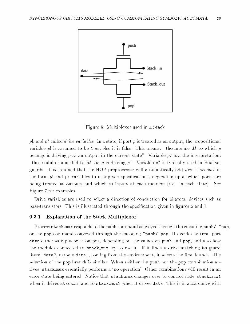
Figure �� Multiplexor used in a Stack
p!� and p� called drive variables� In a state� if port p is treated as an output� the propositional
variable p! is assumed to be true� else it is false� This means� �the module M to which p
belongs is driving p as an output in the current state�� Variable p� has the interpretation�
�the module connected to M via p is driving p�� Variable p� is typically used in Boolean
guards� It is assumed that the HOP preprocessor will automatically add drive variables of
the form p! and p� variables to user�given speci�cations� depending upon which ports are
being treated as outputs and which as inputs at each moment i�e� in each state� See
Figure � for examples�
Drive variables are used to select a direction of conduction for bilateral devices such as
pass�transistors� This is illustrated through the speci�cation given in �gures � and �
���� Explanation of the Stack Multiplexor
Process stack mux responds to the push command conveyed through the encoding push��pop�
or the pop command conveyed through the encoding �push�pop� It decides to treat port
data either as input or as output� depending on the values on push and pop� and also how
the modules connected to stack mux try to use it� If it �nds a drive matching its guard
literal data � namely data�� coming from the environment� it selects the �rst branch� The
selection of the pop branch is similar� When neither the push nor the pop combination ar�
rives� stack mux essentially performs a "no operation�� Other combinations will result in an
error state being entered� Notice that stack mux changes over to control state stack mux�
when it drives stack in and to stack mux when it drives data� This is in accordance with

� GANESH GOPALAKRISHNAN
MODULE stack�mux��
PORT INPUT stack�out� push� pop � bit�
OUTPUT stack�in � bit�
BIDIR data � bit
BEHAVIOR
stack�mux��
� � push � �pop � data� � stack�mux��data�
� �push � � pop � stack�out� � stack�mux��stack�out�
� �pop � stack�mux��
stack�mux��D�� �stack�in � D� stack�in� � � �� stack�in� added by preprocessor ��
� � push � �pop � data� � stack�mux��data�
� �push � �pop � stack�mux��
stack�mux��D�� �data � D� data� � � �� data� added by preprocessor ��
� �push � � pop � stack�out� � stack�mux��stack�out�
� �pop � stack�mux��
END stack�mux
Figure �� Illustration of �Drive�s on the Stack Multiplexor

SYNCHRONOUS CIRCUITS MODELED USING COMMUNICATING SYMBOLIC AUTOMATA �
A stack composed of SM� the stack multiplexor� two instances of SC�
the stack cell� and SC� the stack controller�
SCL1SM SCL2
SC
stack_in inl outr inl outr
stack_out outl inr outl inr
op
P1
P2
pop
push
P1 P2
data
SM: Stack-muxSCL1,SCL2: Stack-cellSC: Stack-ctrlr
Figure �� A Stack

�� GANESH GOPALAKRISHNAN
stack�mux��
� � push �� pop �� data� �� stack�mux��data�
� push �� � pop �� stack�out� �� stack�mux��stack�out�
� pop �� stack�mux��
�
�
stack�mux��D�� �stack�in � D� stack�in� � �� �� stack�in� added by preprocessor ��
� � push �� pop �� data� �� stack�mux��data�
� push �� � pop �� stack�out� �� stack�mux��stack�out�
� pop �� stack�mux��
�
�
stack�mux��D�� �data � D� data� � �� �� data� added by preprocessor ��
� � push �� pop �� data� �� stack�mux��data�
� push �� � pop �� stack�out� �� stack�mux��stack�out�
� pop �� stack�mux��
�
�
END stack�mux
Figure �� A Speci�cation of the Stack Multiplexor Violating Well�formedness
our convention that the set of ports con�gured to be outputs is determined by the state�
��� Illustration of Well�formedness Conditions
We can illustrate some of the well�formedness conditions on this example� Suppose the
speci�cation of the �stack multiplexor� were incorrectly written as shown in Figure ��
Consider the �rst guard in state stack�mux� In this guard� port data is used as an input�
However� since data is used as an output in state stack�mux� the �rst clause of WF� is
violated�
While in state stack�mux�� port data is being treated as an input� Now consider the
second guard in state stack�mux�� which is �push�pop�stack�out � It makes the system
go to state stack�mux where the system drives port data� This again violates the �rst
clause of WF� because an input port �turns around� and drives the external world before the
external world had a chance to turn o� its drive� If we remove the choice of a move through
�push�pop�stack�out � we force the system to make a transition from push��pop����
to �push��pop���� which is a �neutral state�� changing over from push��pop���� to
�push�pop���� can be seen to be in violation of WF� � in fact� the requirement of non�
overlap between push and pop is what is getting violated!

SYNCHRONOUS CIRCUITS MODELED USING COMMUNICATING SYMBOLIC AUTOMATA ��
The speci�cation in Figure � satis�es all the well�formedness checks�
���� Preprocessings Before par
Before we can compose two modules M� and M� using par� where M� and M� have drive
variables� the drive variables must be preprocessed as described below� to take into account
their intended meaning� The desired semantics of p� is to specify that p must be driven from
outside� Thus� if p � PM� and q � PM� are connected by being renamed to a common
name r�p � r � r�q� and if this connection is not exported from parM��M�� we know
that p� means q!� and q� means p!� Thus� for every such use of p�� we substitute q!� and for
every such use of q�� we substitute p!�
If� however� p and q are connected� i�e�� if r�p � r � r�q� and if r is exported from
parM��M�� then p� means q! � r�� and likewise q� means p! � r�� meaning that p can be
driven from �outside� by either M� driving p via q� or the external world driving p via r�
These preprocessings are also performed�
Occurrences of port outputs of the form �p!� are also subject to preprocessing� If p and
q are connected and the connection is not exported� every occurrence of p! � � in M� is
replaced with two port assertions� p! � � and q! � � � this says �since p is being driven by
M�� q may not be driven by M��� Likewise� every occurrence of q! � � in M� is replaced
with q! � � and p! � �� On the other hand� if the connection is exported via r� r! � � is
also asserted� The purpose of asserting q! � � in M� and p! � � in M� is to check for the
consistency of drives during par� each node must be subject to at most one drive� hence we
are adding extra drive assertions that prevent the �other port� from driving the same node�
After performing the above transformations� par can be invoked as described before�
�� The Stack Cell� SC
The operations of the stack cell are described in Figure ���
The additions by the preprocessor are outl� � � and outr� � �� Also� wherever ports
�p� are used� the drive variables �p � will be added by the preprocessor in the guard ex�
pression� They are not shown for brevity� For example� the line
�� do push �� � shr �� trl �� shl �� trr �� scl�inl�S��
would actually look like
�� do push �� � shr �� shr� �� trl �� trl� �� shl �� shl�
�� trr �� trr� �� inl� �� scl�inl�S��

�� GANESH GOPALAKRISHNAN
scl�S��S��� �outl � �S�� outr � �S�� outl� � �� outr� � �
�
�� isolate �� �shr � �trl � �shl � �trr � scl�S��S��
�� do push �� � shr � �trl � �shl � �trr � scl�inl�S��
��replenish�� � �shr � �trl � �shl � trr � scl�S��inv�S���
�� do pop �� � �shr � �trl � shl � �trr � scl�S��inr�
��replenish�� � �shr � trl � �shl � �trr � scl�inv�S���S��
Inl
Outl
Shr
trr
trl
Shl
Outr
inr
S1 S2
Figure ��� A Stack Cell
SYNCHRONOUS CIRCUITS MODELED USING COMMUNICATING SYMBOLIC AUTOMATA ��
sc��s��s�� dtrr�dshl�dtrl�dshr�� �trr�dtrr�shl�dshl�trl�dtrl�shr�dshr
�
� �p� � �p� � sc��s��s�� ��������
� p� � �p� � sc��op�s�� �����s��s��
sc��s��s�� dtrr�dshl�dtrl�dshr�� �trr�dtrr�shl�dshl�trl�dtrl�shr�dshr
�
� �p� � �p� � sc��s��s�� ��������
� �p� � p� � sc��s��op� �s��s������
P2
P1
OP
inv3
inv4
g1
g2
g3
g4
trr
shl
S1
S2
inv1
inv2
trl
shr
Figure ��� A Stack Controller
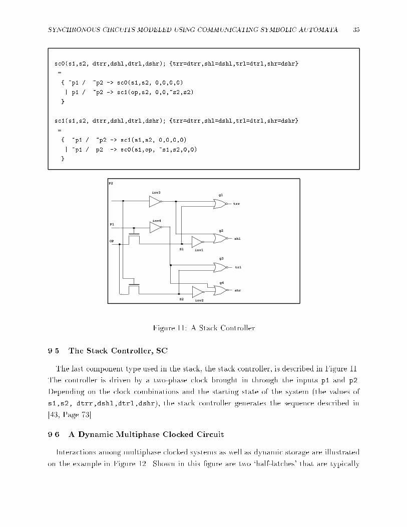
�� The Stack Controller� SC
The last component type used in the stack� the stack controller� is described in Figure ���
The controller is driven by a two�phase clock brought in through the inputs p� and p�
Depending on the clock combinations and the starting state of the system the values of
s��s� dtrr�dshl�dtrl�dshr� the stack controller generates the sequence described in
���� Page ����
� A Dynamic Multiphase Clocked Circuit
Interactions among multiphase clocked systems as well as dynamic storage are illustrated
on the example in Figure ��� Shown in this �gure are two "half�latches� that are typically

�� GANESH GOPALAKRISHNAN
�� First specify the type latch� then create two instances l� and l� ��
�� Instance creation will be shown later ��
MODULE latch
PORT
INPUT in� phi
OUTPUT out
BEHAVIOR
latch�D�� �out�D
� � phi � � in� � latch��in�
� �in� � latch�D�
� �phi � latch�D�
END latch
phi1 phi2
in1 in2 out2g2g1
out1
Phi1
Phi2
Figure ��� Multiphase interactions

SYNCHRONOUS CIRCUITS MODELED USING COMMUNICATING SYMBOLIC AUTOMATA ��
cascaded to form a full latch� We will describe module latch that describes how one of these
half�latches works� We omit the subscripts � and when presenting latch�
Process latch starts in state latch�D�� with its output having value D� its present state�
If phi is found true� and if in in is driven from outside� the next steady state is one
where out��in� else if �in or �phi� the old state D is held out� Notice that the inverter delay
is not captured� This is because the system is assumed to attain steady state�however long
it takes�before the next excitation is applied� If in is not driven from outside � in then
the charge on the gate node is retained� as evidenced by the execution going back to state
latch�D��
If l� and l are cascaded� and the clock sequence �phi��phi� phi��phi� �phi���phi�
�phi��phi� � � �� is applied� l� and l� respond to clock wires cw of their own concern phi�
and phi� respectively� For example� while l is making a phi move� l� would be making
a �phi� move� In this manner� in a multi�phase clocked system described in HOP� a subset
of the modules can be making "useful� moves� whereas the others are making "useless� idling�
or �self loop� moves�
�� Summary� and Conclusions
We have described the HOP automaton model and presented its syntax directed semantics�
We have attempted to clarify many of the notions underlying formal modeling of synchronous
hardware� and make a coherent presentation of the formal semantics of synchronous hard�
ware� stating well�formedness conditions� as well as the adequacy thereof� This work can
open up new opportunities to build synchronous hardware design and debugging tools that
check for as many errors as possible at the syntactic level� infer the behavior of a structural
description� and assist in the formal veri�cation of system descriptions�
HOP was �rst implemented using Common Lisp and FROBS ����� par was realized as
an algorithm PARCOMP that has since been used with great success in debugging several
designs see ���� for example� Earlier versions of PARCOMP su�ered from the following
problems� � the simpli�cation of guard expressions was ad hoc� � well�formedness checks
were not incorporated into PARCOMP� � the implementation was based on a notion of
global clocking� We plan to re�implement PARCOMP based on the new HOP model� A
related implementation e�ort ���� proposes the use of extended BDD models to make syn�
chronous system veri�cation more e cient� These ideas will be incorporated into the HOP
system�
Acknowledgements� Helpful discussions with Professor Eduard Cerny of the University of
Montreal and Professor Steven Johnson of the University of Indiana are gratefully acknowl�

�� GANESH GOPALAKRISHNAN
edged�
References
�� Zvi Kohavi� Switching and Automata Theory� Tata McGraw Hill� �����
�� David Ku and Giovanni De Micheli� HardwareC � A Language for Hardware Design�
Version ���� Technical Report CSL�TR�������� Computer Science Laboratory� Stanford
University� April �����
�� Mario R� Barbacci� Instruction set processor speci�cations isps� The notation and its
applications� IEEE Transactions on Computers� C����������� January �����
�� Vhdl language reference manual� August ����� Intermetrics Report IR�MD������� See
also IEEE Design and Test� April ���
�� Donald E� Thomas and Philip Moorby� The Verilog Hardware Description Language�
Kluwer Academic Publishers� ����� ISBN ��������������
�� Steven D� Johnson� Synthesis of Digital Designs from Recursion Equations� The MIT
Press� ����� An ACM Distinguished Dissertation������
�� Mary Sheeran� mufp� a language for vlsi design� In Proceedings of the ACM Symposium
on Lisp and Functional Programming� pages �������� �����
�� Raymond Boute� System semantics� Principles� applications� and implementation� ACM
Transactions on Programming Languages and Systems TOPLAS�� ������������ Jan�
uary �����
�� P� Caspi� D�Pilaud� N�Halbwachs� and J�A�Plaice� LUSTRE� A declarative language for
programming synchronous systems� In Proceedings of the �th Annual Symposium on
Principles of Programming Languages� pages �������� ACM� �����
��� Gerard Berry and Laurent Cousserat� The ESTEREL synchronous programming lan�
guage and its mathematical semantics� In S�D�Brookes� A�W�Roscoe� and G�Winskel�
editors� Seminar on Concurrency� LNCS �� pages �������� Springer�Verlag� �����
��� C� A� R� Hoare� Communicating Sequential Processes� Prentice�Hall� Englewood Cli�s�
New Jersey� �����
��� Occam programming manual� �����

SYNCHRONOUS CIRCUITS MODELED USING COMMUNICATING SYMBOLIC AUTOMATA ��
��� Vincenza Carchiolo� Alberto Faro� Orazio Mirabella� Giuseppe Pappalardo� and
Giuseppe Scollo� A LOTOS speci�cation of the PROWAY highway service� IEEE Trans�
actions on Computers� C�������������� November �����
��� Michael Gordon� HOL� A proof generating system for Higher Order Logic� In Graham
Birtwistle and P�A�Subrahmanyam� editors� VLSI Speci�cation� Veri�cation and Syn�
thesis� pages ������� Kluwer Academic Publishers� Boston� ����� ISBN���������������
��� Boyer and Moore� A Computational Logic� Academic Press� �����
��� Warren A� Hunt Jr� The mechanical veri�cation of a microprocessor design� In D� Bor�
rione� editor� From HDL Descriptions to Guaranted Correct Circuit Designs� Elsevier
Science Publishers B�V� North Holland� ����� Proc of the IFIP WG ���� Working
Conference with the same title��
��� I�S�Dhingra� Formal veri�cation of a design style� In Graham Birtwistle and
P�A�Subrahmanyam� editors� VLSI Speci�cation� Veri�cation and Synthesis� pages ����
���� Kluwer Academic Publishers� Boston� ����� ISBN���������������
��� Michael J�C� Gordon� Mechanizing programming logics in higher order logic� In
G�Birtwistle and P�A�Subrahmanyam� editors� �� Ban� Hardware Veri�cation Work�
shop� Ban�� June ��� ����� Invited Paper� to appear as a chapter in a forthcoming
Springer�Verlag book�
��� Albert John Camilleri� Mechanizing the failures model of csp in hol� IEEE Transactions
on Software Engineering� �� September �����
��� Ganesh C� Gopalakrishnan� Richard Fujimoto� Venkatesh Akella� and Narayana Mani�
HOP� A process model for synchronous hardware� semantics� and experiments in process
composition� Integration� The VLSI Journal� pages �������� August �����
��� Narayana Mani� Behavioral simulation from high level speci�cations� Master�s thesis�
Dept� of Computer Science� University of Utah� Salt Lake City� UT ������ May �����
��� Prabhat Jain� Ganesh Gopalakrishnan� and Prabhakar Kudva� Veri�cation of regular
arrays by symbolic simulation� Technical Report UUCS�TR�������� University of Utah�
Department of Computer Science� October ����� Submitted to the Brown�MIT Advanced
VLSI Workshop�
��� Prabhakar Kudva� PCA� An algorithm for the Parallel Composition of regular Arrays�
����� Implementation in Standard ML� plus software documentation�

� GANESH GOPALAKRISHNAN
��� Ganesh C� Gopalakrishnan� Richard M� Fujimoto� Venkatesh Akella� N�S� Mani� and
Kevin N� Smith� Speci�cation�driven design of custom architectures in hop� In
G�Birtwistle and P�A�Subrahmanyam� editors� Current Trends in Hardware Veri�cation
and Automated Theorem Proving� chapter �� pages �������� Springer�Verlag� �����
��� Ganesh C� Gopalakrishnan� Narayana Mani� and Venkatesh Akella� A design validation
system for synchronous hardware based on a process model� A case study� In Proceedings
of the IMEC�IFIP Workshop on Applied Formal Methods for Correct VLSI Design�
Leuven� Belgium� pages �������� November �����
��� Ganesh C� Gopalakrishnan� Speci�cation and veri�cation of pipelined hardware in HOP�
In Proc� Ninth International Symposium on Computer Hardware Description Languages�
pages �������� �����
��� Ganesh C� Gopalakrishnan� Narayana S� Mani� and Venkatesh Akella� Parallel compo�
sition of lock�step synchronous processes for hardware validation� Divide�and�conquer
composition� In J�Sifakis� editor� Springer Verlag Lecture Notes in Computer Science�
No���� Automatic Veri�cation Methods for Finite�State Systems� International Work�
shop� Grenoble� France� June ��� pages �������� Springer�Verlag� �����
��� Ganesh Gopalakrishnan� Prabhat Jain� Venkatesh Akella� Luli Josephson� and Wen�Yan
Kuo� Combining veri�cation and simulation� In Carlo Sequin� editor� Advanced Research
in VLSI � Proceedings of the University of California Santa Cruz Conference� The
MIT Press� ����� ISBN ������������
��� Venkatesh Akella and Ganesh Gopalakrishnan� High level test generation via process
composition� In Designing Correct Circuits� Oxford� �� pages ������� Springer Ver�
lag� ����� Proceedings of the DCC Workshop� Oxford� September� �� published in
Springer�s new series �Workshops in Computing��
��� Prabhat Jain and Ganesh Gopalakrishnan� Towards making symbolic simulation based
veri�cation e cient� November ����� Submitted to the IEEE Transactions on CAD� An
earlier version has been submitted to the Design Automation Conference� ��
��� Ganesh Gopalakrishnan and Richard Fujimoto� Design and veri�cation of the rollback
chip using hop� A case study of formal methods applied to hardware design� Technical
Report UU�CS�TR�������� University of Utah� Department of Computer Science� �����
Submitted to the ACM Transactions on Computer Systems�

SYNCHRONOUS CIRCUITS MODELED USING COMMUNICATING SYMBOLIC AUTOMATA �
��� Wayne Wolf� Andres Takach� and Tien�Chien Lee� Architectural optimization meth�
ods for control�dominated machines� In High�Level VLSI Synthesis� chapter ��� Kluwer
Academic Press� �����
��� Michel Langevin and Eduard Cerny� Comparing generic state machines� In Proc� of the
Workshop on Computer�Aided Veri�cation� Aalborg� Denmark� July �����
��� Ghislaine Thuau and Daniel Pilaud� Using the declarative language lustre for circuit
veri�cation� In Designing Correct Circuits� Oxford� �� pages �������� Springer Ver�
lag� ����� Proceedings of the DCC Workshop� Oxford� September� �� published in
Springer�s new series �Workshops in Computing��
��� Michael Gordon� Register transfer systems and their behavior� In Proc� of the �th
International Conference on Computer Hardware Description Languages� �����
��� Randal E� Bryant and Carl�Johan Seger� Formal veri�cation of digital circuits using
ternary system models� Technical Report CMU�CS�������� School of Computer Science�
Carnegie Mellon University� May ����� Also in the Proceedings of the Workshop on
Computer�Aided Veri�cation� Rutgers University� June� �����
��� Carl�Johan Seger and Je�rey Joyce� A two�level formal veri�cation methodology using
HOL and COSMOS� Technical Report ������ Dept� of Computer Science� University of
British Columbia� Vancouver� B�C�� June �����
��� Randal E� Bryant� Derek L� Beatty� Karl Brace� Kyeongsoon Cho� and T� She#er� Cos�
mos� A compiled simulator for mos circuits� In Proc� ACM�IEEE ��th Design Automa�
tion Conference� pages ����� June �����
��� Zhou Chaochen and C�A�R� Hoare� A model for synchronous switching circuits and
its theory of correctness� ����� Proceedings of the DCC Workshop� Oxford� September�
�� published in Springer�s new series �Workshops in Computing��
��� Glynn Winskel� A compositional model of mos circuits� In Graham Birtwistle and
P�A�Subrahmanyam� editors� VLSI Speci�cation� Veri�cation and Synthesis� pages ����
���� Kluwer Academic Publishers� Boston� ����� ISBN���������������
��� David Musser� Paliath Narendran� and William Premerlani� Bids� A method for specify�
ing and verifying bidirectional hardware� In Graham Birtwistle and P�A�Subrahmanyam�
editors� VLSI Speci�cation� Veri�cation and Synthesis� pages �������� Kluwer Academic
Publishers� Boston� ����� ISBN���������������

�� GANESH GOPALAKRISHNAN
��� John E� Hopcroft and Je�rey D� Ullman� Introduction to Automata Theory� Languages�
and Computation� Addison Wesley� �����
��� C� A� Mead and L� Conway� An Introduction to VLSI Systems� Addison Wesley� �����