Embed Size (px)
Citation preview
Game Engine Support for Terrain Rendering in Architectural Design
T. Yang, B. C. Wünsche, and R. J. Lobb
Graphics Group, Dept. of Computer Science, University of Auckland, Private Bag 92019, Auckland, New Zealand.
[email protected], [email protected], [email protected]
Abstract Game engines are relatively low-cost but powerful systems for creating and exploring virtual environments, and are increasingly used in the fields of architecture and urban planning. Traditionally urban planners and landscape architects used small-scale hand-modelled terrains. However, in order to increase both realism and modelling efficiency it is preferable to use computer generated terrains obtained from remote sensing data. Unfortunately many game engines are designed to use relatively small infinitely repeating terrain blocks. In this paper we analyse how the popular Torque terrain engine, which is used by the Department of Architecture of the University of Auckland, can be modified and extended for architectural purposes. The ultimate limitations of the terrain engine are identified and the terrain engine is evaluated on its suitability for architectural design. We explain how large scale terrains can be incorporated into the engine design and we propose a way to integrate the hardware-friendly chunked level-of-detail terrain rendering algorithm into the terrain engine. Our results show that the proposed implementation makes better use of the GPU of modern graphics cards and it frees CPU load for use by other modules of an architectural design tool.
Keywords: Game engine, architectural design, terrain visualization, level-of-detail
1 Introduction Over the past couple of years architecture researchers have started to embrace game engines, which are programming frameworks for the rapid development of computer games, to visualize buildings and the outside world [1,2]. Game engines are a promising architectural design tool for the following reasons [1]:
• They usually employ cutting-edge computer graphics techniques, to support enjoyable real-time interactive exploration of the world.
• They are usually designed for home PCs and thus they are cheap and don’t require expensive hardware devices.
• On-line massive multiplayer (OMM) game engines provide a collaborative environment that is very suitable for architectural teamwork.
The terrain rendering ability of game engines contributes greatly to the realism of a computer-generated virtual environment where 3D building models are embedded. The School of Architecture of the University of Auckland has been exploring the usage of game engines since 2001 [3]. Their work is based on the Torque Game Engine (TGE) [4] which
has a large user community for game development and simulations.
1.1 Motivation User feedback from the School of Architecture identified the following limitations and shortcomings of the terrain engine in TGE:
• The engine can load only 256×256 image files as terrain data. However, the real world terrain data exists in lots of different formats and different dimensions. Architects have to use pre-processing tools to convert the data into image files, and divide the data manually into 256×256 blocks before importing. Most of those processing tools are either expensive or not easy to use.
• The TGE terrain engine only stores one terrain block. The whole world is constructed by tiling the same terrain block in all directions to infinity. Architects cannot represent a real area larger than one terrain block without repeating it.
• Most architecture labs and workshops use modern rendering hardware. They want the engine to take full advantage of the hardware
power. However, the TGE terrain engine does not make use of the capabilities of modern graphic cards.
Although our motivations come from architects and refer to the Torque game engine, the listed problems are common to many publicly available game engines. Also in recent years an increasing part of the scientific community has started to utilize game engines as a freely available tool for interactive collaborative visualization of large and complex data sets. Hence our research is potentially of interest to a large part of the Science and Engineering community.
This paper is structured into four parts. The next section gives an overview of terrain data formats and algorithms for terrain visualization. We then introduce the TGE terrain engine and explain its capabilities and limitations. The following section presents our modified terrain engine which makes it possible to load and process large out-of-core terrains. We conclude with an evaluation of our work and show a real-world example.
2 Terrain Data and Terrain Visualization
2.1 Terrain Data Formats Terrain data exists in various data formats; the two most popular categories are vector and raster data formats [5]. Vector data represents the terrain in terms of points (mountain peaks), lines (contour lines, rivers, coastlines) and polygons in a geographic coordinate system. Raster data represents the terrain as a grid of cells with one height value for each grid point. The resulting data sets are usually referred to as Digital Elevation Maps (DEM). The most popular terrain data formats in the field of architecture are:
• AutoCAD DXF (.dxf) [6] is a vector data format created by AutoDesk and supported widely by CAD (Computer-Aided Design) applications. It is also an industry standard exchange file format for transferring data between CAD and GIS (Geographic Information System) applications. Most digital architectural designs (of buildings or terrains) are in AutoCAD DXF format.
• ESRI Shape File (.shp) [7] is the native vector data format for ESRI products, such as ArcINFO. A large amount of GIS data exists in this format, which is supported by almost all GIS tools.
• Image formats, such as PNG, JPEG, and TIFF are raster data formats that are commonly used among architects and are also used to represent GIS data in some GIS applications. An image represents a terrain as a digital elevation map where the colour (gray scale value) of a pixel corresponds to a height value. It is usually easy to convert between two different image formats and
both lossless and lossy compression techniques are readily available.
• USGS DEM (.dem) [8] is the raster data produced from map contours or aerial photography by the United States Geological Survey. The USGS DEM terrain data takes advantage of both the precision of vector data formats and the simplicity of raster data formats. However, it is not easy to find high resolution terrain data in this format for areas outside the U.S.A.
Terrain data of New Zealand can be obtained from Land Information New Zealand (LINZ) [9] and exists in two formats: Topographic data is provided as digital vector data at 1:50,000 scale in ESRI Shape File format and comes from the New Zealand Topographic Database (NZTopo) [10]. Aerial photographs are available as low resolution JPEG satellite images with a resolution of 25m×25m, and as high resolution JPEG and TIFF satellite images with a resolution of 2.5m×2.5m [9].
2.2 Terrain Visualization Digital elevation maps (DEM) are most commonly stored as either regular grids or as Triangulated Irregular Networks (TIN) where irregular sample points are connected to form a triangle mesh. A regular grid based height field representation has the advantage of simplicity, since only the origin, grid spacing and height values need to be stored. Based on this, hierarchical tree structures can be defined by sub-dividing the grid, and mesh simplification algorithms can recursively process the hierarchies. However, since the sub-division of the grid is constrained by grid vertices, the generated approximation is not usually optimal considering all possible triangulations. TINs are a more general representation and for the same number of polygons usually result in meshes with a better visual quality. However, a TIN requires each sample value to be stored as a quadruple (x, y, z, height).
Because of the storage simplicity and processing convenience, the regular grid based terrain representation is commonly adopted in game engines. In order to achieve fast rendering of large meshes view-dependent continuous level-of-detail (VLOD) methods are employed. VLOD algorithms represent different parts of a mesh at different resolutions in order to obtain approximately equally sized polygons after projection onto the view plane during rendering.
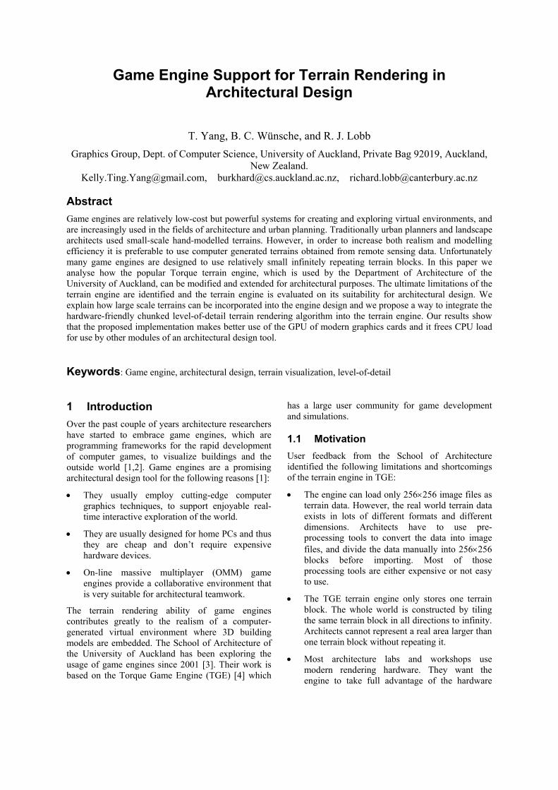
3 The TGE Terrain Engine Figure 1 illustrates the design of the TGE terrain engine. The terrain itself is represented by a terrain block which is a 256x256 regular grid of height values (represented as a 256x256 gray scale image). The terrain block can be tiled in order to represent
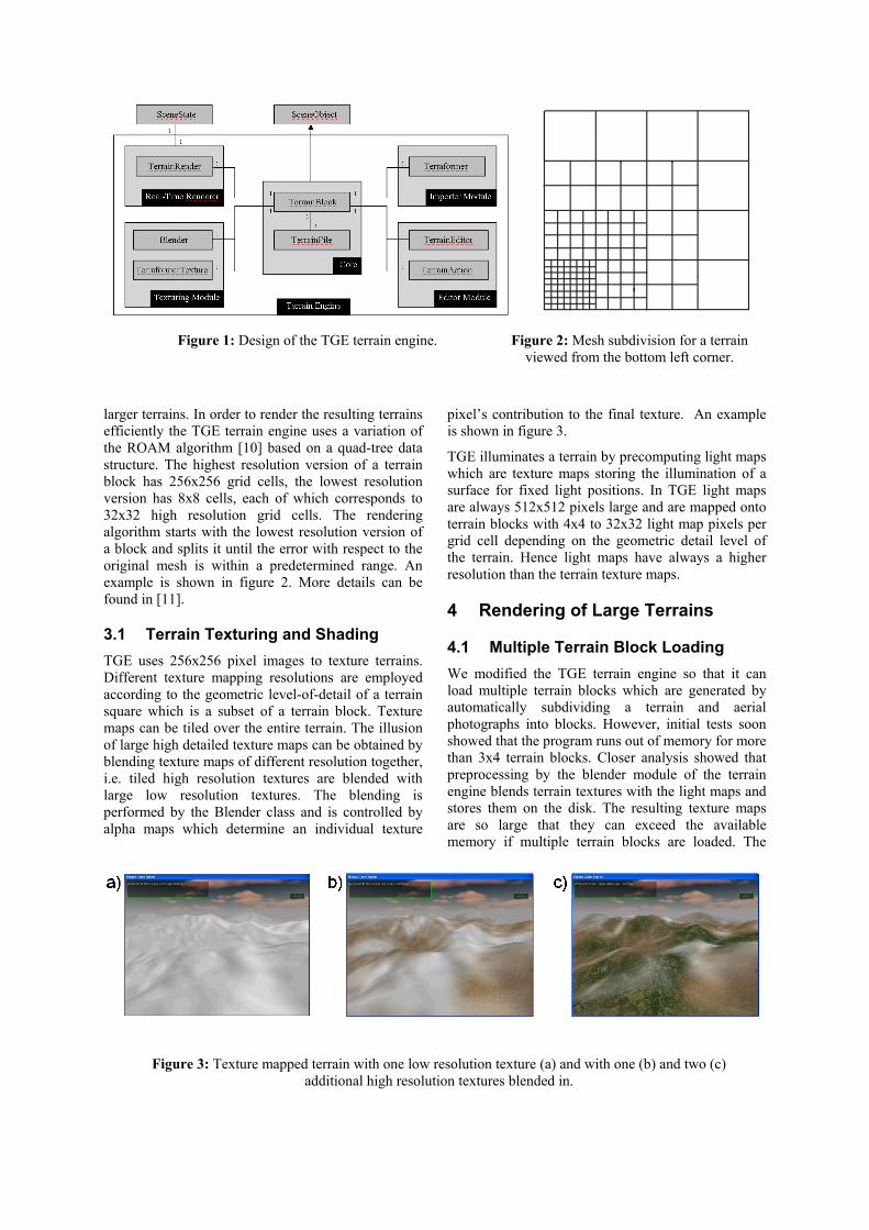
larger terrains. In order to render the resulting terrains efficiently the TGE terrain engine uses a variation of the ROAM algorithm [10] based on a quad-tree data structure. The highest resolution version of a terrain block has 256x256 grid cells, the lowest resolution version has 8x8 cells, each of which corresponds to 32x32 high resolution grid cells. The rendering algorithm starts with the lowest resolution version of a block and splits it until the error with respect to the original mesh is within a predetermined range. An example is shown in figure 2. More details can be found in [11].
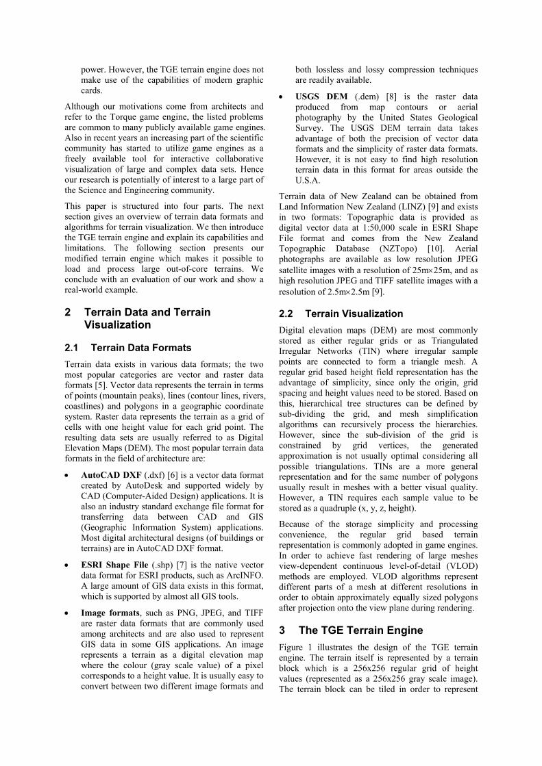
3.1 Terrain Texturing and Shading TGE uses 256x256 pixel images to texture terrains. Different texture mapping resolutions are employed according to the geometric level-of-detail of a terrain square which is a subset of a terrain block. Texture maps can be tiled over the entire terrain. The illusion of large high detailed texture maps can be obtained by blending texture maps of different resolution together, i.e. tiled high resolution textures are blended with large low resolution textures. The blending is performed by the Blender class and is controlled by alpha maps which determine an individual texture
pixel’s contribution to the final texture. An example is shown in figure 3.
TGE illuminates a terrain by precomputing light maps which are texture maps storing the illumination of a surface for fixed light positions. In TGE light maps are always 512x512 pixels large and are mapped onto terrain blocks with 4x4 to 32x32 light map pixels per grid cell depending on the geometric detail level of the terrain. Hence light maps have always a higher resolution than the terrain texture maps.
4 Rendering of Large Terrains
4.1 Multiple Terrain Block Loading We modified the TGE terrain engine so that it can load multiple terrain blocks which are generated by automatically subdividing a terrain and aerial photographs into blocks. However, initial tests soon showed that the program runs out of memory for more than 3x4 terrain blocks. Closer analysis showed that preprocessing by the blender module of the terrain engine blends terrain textures with the light maps and stores them on the disk. The resulting texture maps are so large that they can exceed the available memory if multiple terrain blocks are loaded. The
Figure 1: Design of the TGE terrain engine.
Figure 3: Texture mapped terrain with one low resolution texture (a) and with one (b) and two (c) additional high resolution textures blended in.
Figure 2: Mesh subdivision for a terrain viewed from the bottom left corner.
following example illustrates the problem:
The TGE terrain engine stores terrain height values as 4 byte floating point numbers. Thus, a single terrain block with 256× 256 height values requires 4*256*256=218 bytes memory. Terrain textures at the highest level of detail have 32×32 pixel per grid cell. Each texel is stored as a 3 byte RGB triple. If the terrain textures are blended with the light map the resulting texture requires 3*32*32*256*256=3*226 ≈ 200 MBytes memory.
A possible solution is to dispense with light maps by using hardware lighting calculations and to blend in the multiple textures during rendering using the multi-texturing capabilities of modern graphic cards. However, this is only a partial solution since today’s GIS and remote sensing techniques produce terrain height-field data and satellite images which are too large to be processed in main memory. Hence it is necessary to extend the TGE to handle out-of-core data sets.
4.2 Chunked Level-of-Detail Implementation
After researching various terrain rendering algorithms [11] we decided that the recently proposed Chunked Level-of-Detail (LOD) [13] algorithm is the most suitable solution for our problem. The chunked LOD algorithm is based on an adaptive quad-tree data structure of the mesh which is built in a pre-processing step. Different levels in the tree store terrain chunks at different LODs, together with their bounding volumes and maximum geometric errors. The run-time routine then selects terrain chunks for rendering based on a view-dependent screen-space error metric that considers both the stored geometric errors and the moving view point. Cracks are filled with vertical patches, known as “skirts”. A vertex morphing technique is used to eliminate popping artefacts. Because the quad-tree representation of the mesh is precomputed fewer computations are performed on the CPU and selected chunks are sent to the graphics card and processed by the GPU.
In order to integrate the Chunked LOD algorithm into Torque without affecting other Torque components we designed an interface between the terrain engine and the other modules of Torque. The interface hides methods and variables of the terrain engine. We extended the terrain loader of Torque so that it can load terrain data of different types and arbitrary dimensions. A Chunked LOD pre-processing tool is used to encode the loaded terrain data into an adaptive quad-tree structure which is a subclass of the Torque SceneObject class. We then integrated the Chunked LOD algorithm into the rendering engine of Torque. Hence when Torque traverses the scene graph for rendering, using polymorphism it automatically uses the Chunked LOD algorithm for a terrain in the above described format.
In order to enable the user to use different terrain data formats we use the Geospatial Data Abstraction Library (GDAL) [12]. A dataset in the GDAL is a list of related data layers and some common information such as size, the geo-referencing transform, and the coordinate system definition.
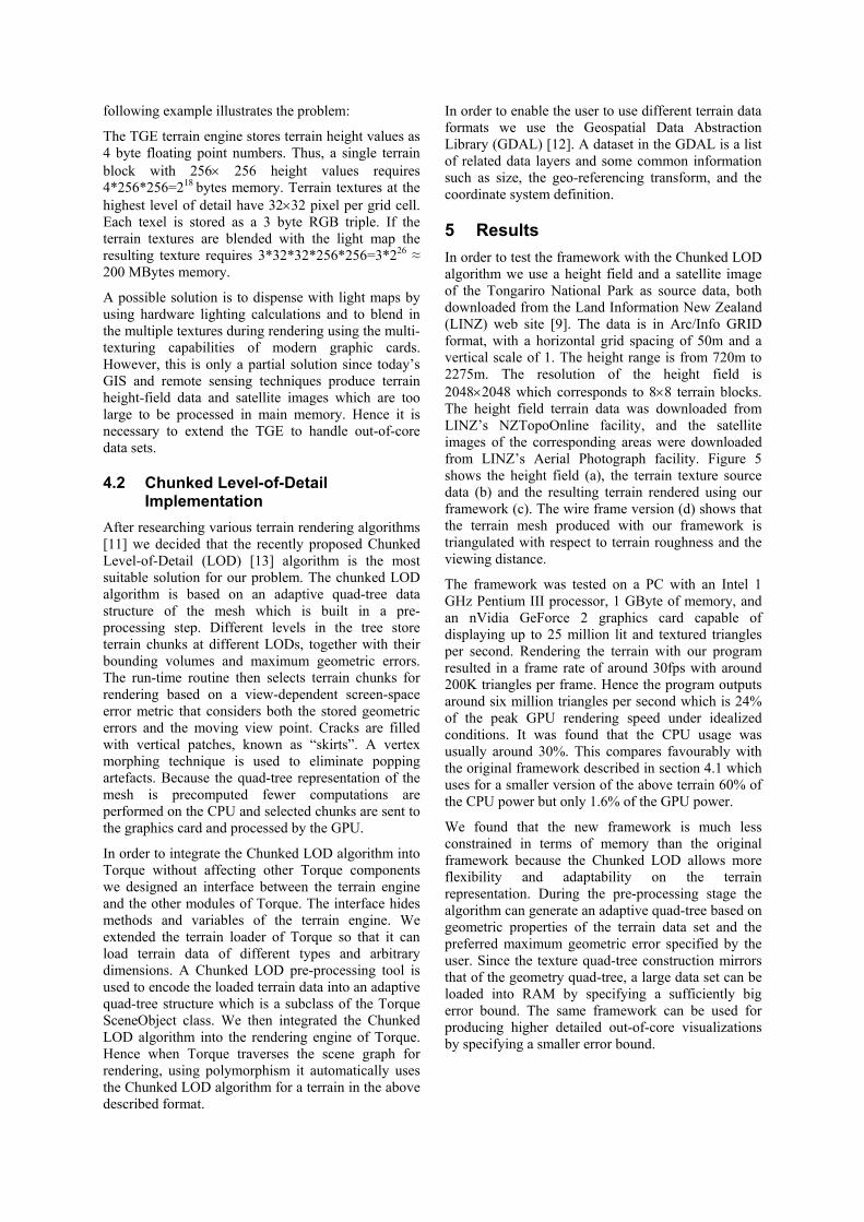
5 Results In order to test the framework with the Chunked LOD algorithm we use a height field and a satellite image of the Tongariro National Park as source data, both downloaded from the Land Information New Zealand (LINZ) web site [9]. The data is in Arc/Info GRID format, with a horizontal grid spacing of 50m and a vertical scale of 1. The height range is from 720m to 2275m. The resolution of the height field is 2048×2048 which corresponds to 8×8 terrain blocks. The height field terrain data was downloaded from LINZ’s NZTopoOnline facility, and the satellite images of the corresponding areas were downloaded from LINZ’s Aerial Photograph facility. Figure 5 shows the height field (a), the terrain texture source data (b) and the resulting terrain rendered using our framework (c). The wire frame version (d) shows that the terrain mesh produced with our framework is triangulated with respect to terrain roughness and the viewing distance.
The framework was tested on a PC with an Intel 1 GHz Pentium III processor, 1 GByte of memory, and an nVidia GeForce 2 graphics card capable of displaying up to 25 million lit and textured triangles per second. Rendering the terrain with our program resulted in a frame rate of around 30fps with around 200K triangles per frame. Hence the program outputs around six million triangles per second which is 24% of the peak GPU rendering speed under idealized conditions. It was found that the CPU usage was usually around 30%. This compares favourably with the original framework described in section 4.1 which uses for a smaller version of the above terrain 60% of the CPU power but only 1.6% of the GPU power.
We found that the new framework is much less constrained in terms of memory than the original framework because the Chunked LOD allows more flexibility and adaptability on the terrain representation. During the pre-processing stage the algorithm can generate an adaptive quad-tree based on geometric properties of the terrain data set and the preferred maximum geometric error specified by the user. Since the texture quad-tree construction mirrors that of the geometry quad-tree, a large data set can be loaded into RAM by specifying a sufficiently big error bound. The same framework can be used for producing higher detailed out-of-core visualizations by specifying a smaller error bound.
6 Conclusion Although the new framework is still a work in progress, it has been proven to have advantages over the original terrain engine framework in both CPU/GPU usage and RAM consumption. Compared with the original framework, which uses around 1.6% of the GPU power and 60% of the CPU power, the new framework represents a more balanced usage of the GPU and CPU. This frees CPU load for use by other modules of an architectural design tool. The new framework also provides a flexible mechanism to allow large out-of-core datasets to fit into RAM. It solves the fundamental problem with large-scale terrain rendering in the original framework and improves the engine design to be more compatible with modern graphics hardware.
7 Acknowledgements We would like to thank Jules Moloney from the School of Architecture of the University of Auckland, New Zealand, for suggesting this topic and for his help and enthusiasm.
8 References [1] J. Dijkstra, B. de Vries, J. Brosens, R.
Hoekman and D. Willems, Game engines in architecture, URL: http://www.ds.arch.tue.nl/ education/projects/game_engines/index.html.
[2] M. M. F. Shiratuddin and W. Thabet, Virtual Office Walkthrough Using a 3D Game Engine, International Journal of Design Computing, Vol. 4 (2002), URL: http://www. arch. usyd. edu.au/kcdc/journal/vol4/. [3] J. Moloney and R. Armor, StringCVE:
Advances in a Game Engine Based Collaborative Virtual Environment for Architectural Design, Proc. 2nd conference on Construction Applications of Virtual Reality, Virginia Tech., Blacksburg U.S.A. (2003).
[4] The Torque Game Engine, URL: http:// www.garagegames.com/pg/product/view.php ?i=1.
Figure 5: A height field (a) and satellite image (b) of the Tongariro National Park and the resulting terrain rendered with our framework using shaded polygons (c) and a wire frame representation (d).
[5] The Essential Guide to GIS, URL: http://easyweb.easynet.co.uk/~edp/esguide/e g-data/eg-data.htm. [6] Data Exchange File (DXF), URL: http://www.cknow.com/ckinfo/acro_d/dxf_1. shtml. [7] Environmental Systems Research Institute, Inc., “ESRI Shapefile Technical Descrip- tion”, 1998, URL: http://www.esri.com/ library/whitepapers/pdfs/shapefile.pdf. [8] USGS Digital Elevation Model, URL:
http://rockyweb.cr.usgs.gov/elevation/dpi_dem.html.
[9] Land Information New Zealand (LINZ), URL: http://www.linz.govt.nz/rcs/linz/pub/ web/root/home/index.jsp. [10] M. Duchaineau, M. Wolinsky, D. E. Sigeti,
M. C. Miller, C. Aldrich, and M. B. Mineev-Weinstein, “ROAMing Terrain: Real-time optimally adapting meshes”, Proc. Visualization ’97, pages 81-88, 1997.
[11] T. Yang, Game Engine Support for Terrain
Rendering in Architectural Design, MSc thesis, Dept. of Computer Science, University of Auckland, submitted for publication (2004).
[12] GDAL homepage, URL: http://www.
remotesensing.org/gdal/. [13] T. Ulrich, Chunked Level-of-Detail homepage, URL: http://tulrich.com/geekstuff /chunklod.html.


![[Architecture eBook] Architectural Rendering Techniques](https://img.pdfslide.us/doc/110x75/55cf8f0e550346703b9880b7/architecture-ebook-architectural-rendering-techniques-56783efcc9ad6.jpg)