Embed Size (px)
Citation preview

Installation & Parts
Liquid ControLs Group An IDEX Fluid & Metering Business Installation: EM100-10
LectroCount LCR-II®
E3650/E3651 Series
LectroCount LCR-II
Gallons

2
Table of ConTenTs
The most current English versions of all Liquid Controls publications are available on our web site, www.lcmeter.com. It is the responsibility of the local distributor to provide the most current version of LC manuals, instructions, and specification sheets in the required language of the country, or the language of the end user to which the products are shipping. If there are questions about the language of any LC manuals, instructions, or specification sheets, please contact your local distributor.
Publication Updates and Translations
! WaRnInG• Before using this product, read and understand the instructions.• All work must be performed by qualified personnel trained in the proper application, installation, and
maintenance of equipment and/or systems in accordance with all applicable codes and ordinances.• When handling electronic components and boards, always use proper Electrostatic Discharge (ESD) equipment
and follow the proper procedures• Make sure that all necessary safety precautions have been taken. • Provide for proper ventilation, temperature control, fire prevention, evacuation, and fire management.• Provide easy access to the appropriate fire extinguishers for your product. • Consult with your local fire department, state, and local codes to ensure adequate preparation.• Read this manual as well as all the literature provided in your owner’s packet.• Save these instructions for future reference.• Failure to follow the instructions set forth in this publication could result in property damage, personal injury, or
death from fire and/or explosion, or other hazards that may be associated with this type of equipment.
be Prepared
InTRodUCTIon
Safety Procedures ................................................... 2ESD Protection ......................................................... 4Dimensions .............................................................. 5Specifications .......................................................... 6Meter System Overview ........................................... 8LectroCount LCR-II Overview ................................. 10
InsTallaTIon
Installation Overview ............................................... 11LectroCount Ground Strap Kit ................................. 12LectroCount LCR-II Mounting ................................ 14Routing LCR-II Data and Power Cables ................ 17Electronic Temperature Volume Compensation ...... 18Valves ...................................................................... 19 Optical Air and Vapor Eliminators ............................ 23Pulse Output Device (POD) .................................... 24Differential Pressure (∆P) Transducer ..................... 25Remote Display and Auxiliary Outputs .................... 26Printers .................................................................... 27Power Installation .................................................... 28Post Installation ....................................................... 30
bIll of MaTeRIals
External Components .............................................. 32Internal Components ............................................... 33CPU Board .............................................................. 34
aPPendIx
Wiring Tables ........................................................... 36Setup and Lap Pad ................................................. 38Obsolete Products ................................................... 38

3
safeTy PRoCedURes
! WaRnInGPower, input, and output (I/O) wiring must be in accordance with the area classification for which it is used (Class I, Div 2). For North America, installations must be per the U. S. National Electrical Code, NFPA 70, or the Canadian Electrical Code in order to maintain Class I, Division 2 ratings. This may require using connections or other adaptations in accordance with the requirements of the authority having jurisdiction.
WARNING: Explosion Hazard - Substitution of components may impair suitability for Class I, Division 2 applications.
WARNING: Explosion Hazard - When in hazardous locations, turn power OFF before replacing or wiring modules.
WARNING: Explosion Hazard - Do NOT disconnect equipment unless power has been switched OFF or the area is known to be Non-Hazardous.
observe national and local Codes
Before disassembly of any meter or accessory component:
ALLINTERNALPRESSURESMUSTBERELIEVEDANDALLLIQUIDDRAINEDFROM THESYSTEMINACCORDANCEWITHALLAPPLICABLEPROCEDURES.
-Pressure must be 0 (zero) psi. -Close all liquid and vapor lines between the meter and liquid source.
For SafetyRulesRegardingLPG, refer to NFPAPamphlet58 and local authorities.
Failuretofollowthiswarningcouldresultinpropertydamage,personalinjury,ordeathfromfireand/orexplosion,orotherhazardsthatmaybeassociatedwiththistypeofequipment.
! WaRnInG
safely evacuate Piping system

4
esd PRoTeCTIon
Potential damages Caused by exposure to esdTo prevent electrostatic discharge (ESD) damage to LectroCount register electronic components, all LectroCount electronic register truck intallations are required to properly ground truck seat(s) cushions and Epson printers. Prolonged exposure to ESD over weeks, months, or years can corrupt LectroCount registers’ CPU memory and damage the electronic components in LectroCount registers (as well as other electrical components in the truck’s electrical system).
Adjustable, shock-absorbing seats, if not grounded correctly, generate significant amounts of ESD. The pivots and hinges of these seats isolate the seat cushion from an electrical ground. Without an electrical ground, ESD builds between the seat cushion and the operator. This built-up ESD can be transferred back to the LectroCount register from any point of the truck’s electrical system, such as the cabling from the LectroCount register to the cab or the Epson printer.
liquid Controls’ Grounding KitsTo protect electronic components from ESD, all LectroCount truck intallations must include the installation of the LectroCount Ground Strap Kit (PN 82185) and the Epson Printer Ground Wire Kit (PN 82184). Properly grounded seats allow static electricity to “bleed off” the driver and the seat before it can build up, discharge, and damage the LectroCount register or any of the truck’s other electrical components.
The LectroCount Ground Strap Kit will be included with all future LCR-II LectroCount register shipments, and the Epson Printer Ground Wire Kit will be included with all future Epson printer cable kit shipments. Effected part numbers are listed below. For existing installations and previously purchased LectroCount registers and Epson printers, both ground kits are available from LC.
esd Procedural Precautions and lectroCount Register Grounding Installation notesWhen installing or performing maintenance on a LectroCount register, there are certain guidelines that must be followed to safeguard against ESD damage.
ReGIsTeRs noT MoUnTed dIReCTly To The MeTeRIn typical LectroCount installations where the LectroCount register is mounted directly to the meter, the LectroCount housing is grounded through the meter. If the register is not mounted on the meter, you must make sure the LectroCount housing is grounded properly. alternate grounding method Connect the green ground screw (inside the LectroCount housing in the upper right corner) to a known good ground (less than
1 ohm). Use a 12ga. or larger stranded wire.
fIxed InsTallaTIonsLectroCount housings directly mounted to the meter are attached to the earth ground through the meter via the tank and the tank piping ,which is grounded by the electrical system grounding rods. Division 1 fixed installations typically require metal conduit to the conduit hubs for the wiring. The metal conduit provides the necessary ESD protection. Divison 2 installations can ground the LectroCount housing by using shielded cables (or wiring) run through liquidtite (metal/rubber coated). The liquidtite and the liquidtite connectors provide the necessary ESD protection. AC fixed installations require and additional grounding method to ensure a proper ground.alternate grounding method for aC fixed installations Connect the green ground screw (inside the LectroCount housing in the upper right corner) to a known good ground (less than
1 ohm). Use a 12ga. or larger stranded wire.
Follow this procedure each time you open a LectroCount register or approach a LectroCount register with the door open.Before opening the LectroCount register and handling the CPU board, it is important to discharge any ESD that may have built up on your person. To discharge ESD from your person, touch a well-grounded point such as the LectroCount register housing, the meter, the truck piping, or the bumper. When the maintenance is complete and the LectroCount register door is closed, the CPU board is
protected from ESD by the LectroCount register housing which is grounded to the chassis.
. esd Precaution .OpeningLectroCountRegisters
5
dIMensIons
Side
Front
top
rear

6
sPeCIfICaTIons
Input/output specificationsPowerRequirements +9 to +28 Volts DC @ less than 3 Amps for entire register including solenoid valves. The system can operate with either a positive or negative ground.
Pulse Input+5 to +28 volt peak to peak square wave from an open collector transistor. Quadrature or single channel with a directional logic line. Frequency not to exceed 1500 Hz.
Scaled Pulse OutputThe scaled pulse output reflects NET volume if temperature compensation is being used or GROSS volume if temperature compensation is not used. One pulse will be output per least significant digit of the display, i.e., a system set to read in 1/10 gallon will provide one pulse per 1/10 gallon (10 pulses per gallon). 150 mA sinking capability.
Auxiliary 1 Output and Auxiliary 2 OutputThis output can be used to add features such as a pump control or additive injection.
Aux 1 (Out 1)Open drain output common to the negative power input line. Sinking capability up to 1 Amp. Maximum circuit voltage is same as power supplied to LCR-II.
Aux 2 (Out 2)Open drain output common to the negative power input line. Sinking capability up to 150 mA. Maximum circuit voltage is same as power supplied to LCR-II.
Solenoid 1 Output (Out 7)/ Solenoid 2 Output (Out 6) - Valve ControlOpen drain transistor capable of sinking 2 Amps. Maximum open circuit voltage is same as power supplied to LCR-II.
Solenoid 3 Output (Out 8) - Optical Air EliminatorOpen drain transistor capable of sinking 1 Amp maximum. Open circuit voltage is same as power supplied to LCR-II.
Optical Sensor (In 5)Three wire sensor, 0.05 Amp maximum.
OUT 4/OUT 5 to Remote Electronic DisplayOpen drain transistor capable of sinking 1 Amp. Maximum open circuit voltage is same as power supplied to LCR-II. Pulses are active LOW.
RS-232 I/O PortMeets EIA–232E standard but only incorporates five signaling lines:
• Transmit data• Receive data• Request to Send or Data Set Ready• Clear to Send or Data Terminal Ready• Ground
The printer output port is compatible with the Epson™ TM 290 II, TM 295, TM 300, TMU 200D, TMU 295 printers, Axiohm Blaster, and Okidata™ ML184 printer.
RS-485 I/O PortLine terminations are SAE J1708 standard compatible which allows up to 20 units per network.
RTDFour wire platinum sensor with 100 Ω resistance at 0°C and 138.5 Ω resistance at 100°C. Accuracy per IEC 751 Class B.
Printer (Epson Model 295)Operating temperature: -22° to 104°F (-30° to 40°C). Printer must use multi-part NCR forms and operate without a ribbon (impact image on form) to operate in the low end of temperature range.

7
sPeCIfICaTIons
Mechanical/Climatic suitabilityRatings
IP66
NEMA4X
Operating Temperature: -40° to 158°F (-40° to 70°C)Relative Humidity: 0 to 100%
Dust tight, dust will not enter.Protection against a powerful jet of water from all practical directions.
Either indoor or outdoor use to provide against falling rain, splashing water, and hose-directed water; undamaged by the formation of ice on the enclosure; resists corrosion. Plastic lens is resistance to UV and water immersion. Gaskets are resistant to aging.
eMCCispr AUnitedStates
Regulatory conformance safetyClass I, Division 2, Groups C & D (non-incendive), IP66Class I, Division 2, Groups C & D (non-incendive), IP66
UnitedStates/Canada
Weights & Measures - Custody TransferUnitedStates
Canada
NTEP Certificate of Conformance #86-022. Complies with requirements in NIST hand-books 14 and 44 for use with any approved meter.
Measurements Canada Notice of Approval #AV-2342. Complies with Weights & Measures Acts, Regulations, Specifications, Bulletins, and Rulings/Interpretations including specifica-tions SVM-1 and SVM-2 for use with any approved meter.

8
Meter system Components
MeTeR sysTeMA Liquid Controls meter system not only accurately measures product, it also regulates and purifies product flow in order to produce the optimal conditions for measurement. Optimal systems typically include an air/vapor eliminator, strainer, meter, register, and control valve. The LectroCount LCR-II, a register, serves as the central controller of the meter system. Most components in the meter system are hard wired to the LCR-II via data communication cables. See manual M100-10.
aIR/vaPoR elIMInaToRsAir and vapor eliminators sense and remove air or vapor in the piping before it enters the metering system, ensuring that only liquid will pass through the meter for measurement. Mechanical air eliminators do not require a data connection to the LectroCount LCR-II (in LPG applications, they are often plumbed to a 3-way solenoid which is wired to the LectroCount LCR-II). Optical air eliminators use an optical sensor to monitor liquid levels and a solenoid-actuated valve to turn the vapor vent on and off. The optical sensor and the solenoid valve are connected to the LectroCount LCR-II by separate data cables. See manuals M300-20 and M300-21.
valvesValves control the flow through a metering system. They open the line to initiate custody transfers and close the line to stop custody transfers. Some valves can partially close, slowing the flow rate to a dwell flow on preset deliveries. By slowing the flow rate, valves can lessen the hydraulic shock incurred by the meter system upon shut off and provide accurate preset deliveries. Many valves use solenoid-operated valves that require a hard wired data connection to the LectroCount LCR-II. See manuals M400-11 and M400-40.
eleCTRonIC TeMPeRaTURe volUMe CoMPensaTIon (eTvC) KITIn order to perform temperature compensation equations, the LectroCount LCR-II relies on a temperature probe inserted into the strainer housing. Installation directions for the ETVC kit are included in this manual.
MeTeR sysTeM oveRvIeW
M7 Meter with LectroCount LCR-II Electronic Register, Optical Air Eliminator, High Capacity Strainer, and E-7 Valve
Optical Air Eliminator Refined Fuels
Mechanical Air Eliminator and High Capacity Strainer
Optical Vapor Eliminator LPG and NH3
Solenoid Block Valve
ETVC Kit
E-7 Valve

9
MeTeR sysTeM oveRvIeW
Epson Slip Printer Epson Roll Printer
Remote Display
POD Pulser
∆P Transducer
DMS i1000
Lap Pad
Meter system Components
PUlse oUTPUT devICeThe Liquid Controls Pulse Output Device (POD pulser) converts the rotary motion of a positive displacement flowmeter into electronic pulses. POD pulsers can be used in place of an internal pulser. They are ideal for applications that require explosion proof components in which the LectroCount LCR-II register is installed at a distance from the meter. The POD pulser requires hard wired data communication with the LectroCount LCR-II. See manual EM300-11.
dIffeRenTIal PRessURe (∆P) TRansdUCeRThe differential pressure transducer, common in aviation applications, monitors the differential pressure (pressure drop) across a full flow fuel monitor/water coalescer. The highest differential pressure reached during the custody transfer will then be printed on the ticket. Using interlocks, the LectroCount LCR-II can shut down a custody transfer if the differential pressure meets a preprogrammed differential pressure shutdown value. The ∆P Transducer requires hard wired data communication with the LectroCount LCR-II. See manual EM300-40.
daTa ManaGeMenT sysTeMsThe DMS i1000 is an in-cab computer with a heavy duty lap pad interface. The DMS i1000 streamlines the flow of data between the LCR-II and back office accounting software. The DMS i1000 must be hard wired to the LectroCount LCR-II. See manuals EM200-10 and EM200-11.
laP PadThe lap pad programs and displays all operational functions of the LectroCount LCR registers. It has a large, tactile, alpha-numeric keyboard and a dual line, backlit display. A 3-terminal lap pad adapter is provided with each lap pad. The adapter provides a junction for the lap pad, the printer, and the LCR printer cable.
leCTRoCoUnT ReMoTe dIsPlayThe 2¼" digits on the Liquid Controls LectroCount Remote Display allow operators to view the register totalizer values from distances of up to 100 feet. Hard wire data communication with the LectroCount LCR-II is required. See manual EM100-13.
PRInTeRsPrinters print delivery tickets to provide a physical record of custody transfers. The Epson slip printer is considered the industry standard for many applications. Multi-layered tickets are available to provide a physical record for both customers and business records. The Epson roll printer is ideal for recording multiple custody transfers over an extended time frame.

10
lectroCount lCR-II overview
GeneRal InfoRMaTIonThe Liquid Controls LectroCount LCR-II is a microprocessor-based electronic meter register that can be used for Weights & Measures approved custody transfer actions in mobile or fixed installations. The LCR-II can control a meter system as a stand-alone unit, or it can be used as a slave to a host contoller such as a process controller or an in-cab data management system.
InPUTsIn order to calculate flow measurements from a positive displacement meter, the LCR-II receives a pulse input from an internally mounted quadrature pulser that is mechanically connected to the flow meter (retrofit kits are available for installation onto Neptune, Brooks, and Smith positive displacement meters). This pulse output can also come from a Liquid Controls external POD pulser or another pulse generator. In addition to the pulse input, the LCR-II is equipped with an input for a temperature probe, so the register can compensate volume measurements according to the temperature of the product.
oUTPUTsThe LCR-II is equipped with a scaled pulse output, two auxiliary outputs, and two solenoids outputs. These outputs allow the LCR-II to communicate with meter system accessories such as solenoid-controlled valves, optical air and vapor eliminators, remote displays, printers, and third-party devices.
CoMMUnICaTIonsThe LCR-II is capable of interfacing in RS-232 and RS-485 communication protocols.
hoUsInGThe LectroCount LCR-II housing and base are aluminum die cast and powder coated. The hinge door design provides easy access to the internal connections and a Weights and Measures sealable fastener opposite the hinges. There are seven machined ports, five ½” NPT ports and two ¾” NPT ports, on the back of the LectroCount LCR-II to provide secure cable connections for all external devices.
dIsPlayThe 1” display is a six character, backlit LCD display.
navIGaTIon Keys The LCR-II has two domed navigation keys to perform basic configuration and functions. The keys collapse and recover to give a tactile, positive confirmation of keystrokes.
seleCToR sWITChThe selector switch controls basic stop, run, print, and shift print delivery functions. To perform calibration functions, the cover plate must be removed and the selector switch turned to the six o’clock position.
fUnCTIonalITy and oPeRaTIonThe principle functions of the LectroCount registers include:
• Calibration (single and multipoint)
• Weights & Measures custody transfer (product delivery and ticket generation)
• Metrological data collection
• Presetting by volume
• Multiple production selection
• Security settings
• Air and vapor elimination (with proper accessories)
• Valve control (with proper accessories)
• Electronic temperature volume compensation (ETVC) (with proper accessories)
lCR-II oveRvIeW

11
InsTallaTIon oveRvIeW
Installation overviewIf the LectroCount LCR-II was ordered as part of a meter system, it will arrive mounted on the meter and prewired to the ETVC probe, air eliminator, and valve.
Installation overview for lCR-II ordered with meter system:
1. Ground truck seat cushion. Page 12
2. Install meter system onto truck or fixed installation. Refer to meter manual.
3. Run the LCR-II’s data and power cable to truck cab or power supply. Page 17
4. Connect any additional components to the LCR-II’s CPU board.
5. Mount printer and connect printer data cable. Page 27
6. Connect the LCR-II and the printer to power supply. Page 28
7. Setup and calibrate the LCR-II. Refer to manual EM150-11.
If you are replacing an existing register, you must mount the register onto the meter and make the proper connections to all of the components.
Installation overview for lCR-II ordered without meter system:
1. Ground truck seat cushion. Page 12
2. Mount the LCR-II to the meter. Page 14
3. Run the LCR-II’s data and power cable to truck cab or power supply. Page 17
4. Connect all components to the LCR-II’s CPU board.
5. Mount printer and connect printer data cable. Page 27
6. Connect the LCR-II and the printer to power supply. Page 28
7. Setup and calibrate the LCR-II. Refer to manual EM100-11.
Before installation, check your shipment against the packing list and ensure that no parts are missing. The
packing list is inside the red information packet along with the Installation and Operation Manuals.
CheckEachShipment
Specific installation requirements will vary with the model of the truck, the physical layout of a fixed installation, the configuration of any existing metering equipment, the options
selected, and the type of fluid being metered
InstallationRequirementsVary
This manual explains and details the mechanical installation of the LectroCount LCR-II and the temperature probe as well as the electrical and data installation of all components that connect to the LCR-II. For additional
installation information, refer to the manuals of the other components. All manuals are available at www.lcmeter.com.
ThisManualIncludes
12
leCTRoCoUnT GRoUnd sTRaP KIT
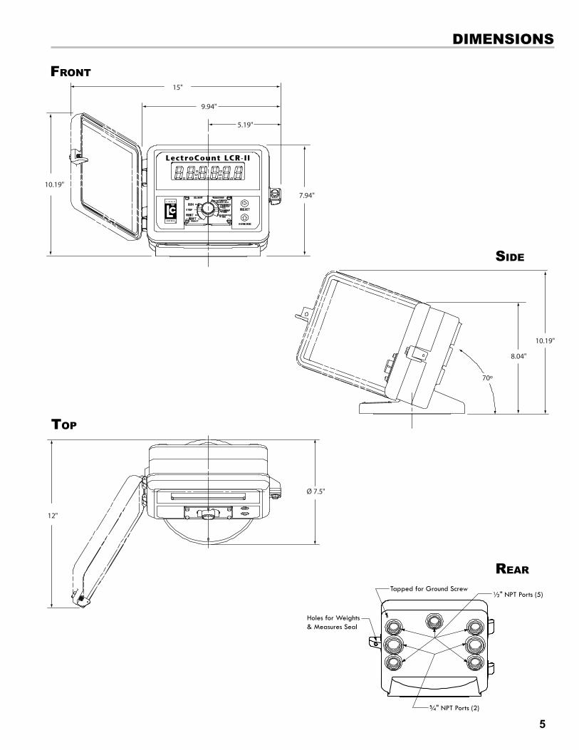
lectroCount Ground strap KitAll seat cushions are grounded in a similar manner. The illustrations on the next page detail the following instructions for grounding three typical types of truck seats. To ground a truck seat:
1. Identify any adjustable, shock absorbing seat in the truck cab. These seats will typically have pivot points, hinges, or other mechanical design features that make seat adjustments possible.
2. Find an existing screw or hole near the back of the seat frame, close to the cab floor. If a hole or screw does not already exist, drill a 9/32” hole in the seat frame.
3. Attach one end of the ground strap to the seat frame bracket using the lock washer, flat washer and nut provided.
4. Find an existing screw or hole, or drill a 9/32” hole, in the part of the seat frame—above all pivots and adjustments—that is attached directly to the seat cushion. Make sure that there are no intervening pivot points, guides, adjustment mechanisms, etc., which could interfere with the ground path between the seat cushion and the ground strap.
4a. If the seat cushion has a wooden base, use a wood screw and washer to attach the strap lug to the bottom of the seat at a point where the seat fabric is attached to the wood. There must be good contact between the seat fabric and ground strap lug.
5. Use the wire ties provided with the kit and tie off the strap so that it doesn’t interfere with the movement of the seat and is clear of traffic areas in the cab.
6. Check the strap for a good ground connection (see below).
Remove any dirt or oxidation from the ground strap contact point. Lock washers should penetrate any
paint to ensure a good electrical connection.
EnsureaGoodGround
6
1
2
3
3
5
8
4
9
LectroCount Ground Strap Kit - 82185
Install the LectroCount Ground Strap Kit before installing the LectroCount register.
. esd Precaution .
Some truck seats, typically passenger seats, are not adjustable and do not require grounding.
GroundedPassengerSeats

13
TyPICal adjUsTable TRUCK seaTs & GRoUnd CheCK
Checking for a Good GroundAfter installing the ground kits, use a multimeter to confirm that the seat and printer are both grounded properly.To check for a good ground connection:
1. Turn OFF all accessories, including the dome light, to prevent other currents from distorting the reading.
2. Take a multimeter and measure the resistance between the brackets the two ground strap bolts are fastened to. Find a clean spot on the brackets without paint to use as contact points. Other bolts on the brackets are often suitable.
2a. If the resistance is less than 3Ω, the system is grounded adequately.
2b. If the resistance is still greater than 3Ω, check for proper metal to metal contact on both ends of the ground strap. Clean any paint, dirt, or oxidation that may block the grounding point. If the resistance remains above 3Ω, attach the ground strap to a different ground point. Repeat the process until the ground resistance is below 3Ω.
If the multimeter reads “MΩ” or “KΩ”, typically, one of the accessories is still on.
TurnOffAccessories
aIR CUshIon seaT - ADjUSTABLE FOR HEIGHT(Bostrom 914 Series, National 2000 Series, or equivalent)
aIR CUshIon seaT - ADjUSTABLE FOR HEIGHT(Dura-Form or equivalent)
benCh seaTs - ADjUSTABLE FOR DISTANCE TO THE STEERING WHEEL(Manufacturer Standard or equivalent)
Typical adjustable Truck seats

14
Neptune Adapter Neptune Coupling
Brooks AdapterSmith Adapter
LCR-II with LPG Meter System
lCR-II MoUnTInG
Mounting overviewTypically, the LectroCount LCR-II is mounted directly onto a flow meter; however, some fixed installations require the register be mounted away from the meter. If the meter is equipped with an external POD pulser, the LCR-II can be mounted up to 1000 wire feet (304 meters) away from the meter (actual distance depends on pulser specifications and wire type).
Adapters are available for other PD meters such as Neptune (PNs 81364, 82641, 82642), FMC Smith (PN 81370), and Brooks/Brodie (PN 81800) meters. Each kit includes installation instructions.
Tips for mounting an lCR-II:• Leave the cover assembly fastened to the base to protect
the internal components.
• Make sure the vertical drive shaft from the meter is attached to the pulser drive shafts.
• Before securing the LCR-II to the meter or mounting bracket, make sure the counter is visible and the keypad and selector switch can be easily operated.
Relieving Internal PressureAll internal pressure must be relieved to zero pressure before disassembly or inspection of the strainer, vapor eliminator, any
valves in the system, the packing gland, and the front or rear covers.
! WaRnInG
Relieving Internal Pressure Procedure for lPG and nh3 Meters6. Slowly crack the fitting on top of the differential valve to
relieve product pressure in the system. Product will drain from the meter system.
7. As product is bleeding from the differential valve, slowly reopen and close the valve/nozzle on the discharge line. Repeat this step until the product stops draining from the differential valve and discharge line valve/nozzle.
8. Leave the discharge line valve/nozzle open while working on the system.
1. Close the belly valve of the supply tank.
2. Close the valve on the vapor return line.
3. Close the manual valve in the supply line on the inlet side of the meter. If no manual valve exists on the inlet side, consult the truck manufacturer for procedures to depressurize the system.
4. Slowly open the valve/nozzle at the end of the supply line.
5. After product has bled off, close the valve/nozzle at the end of the supply line.
Seriousinjuryordeathfromfireorexplosioncouldresultinperformingmaintenanceonanimproperlydepressurizedandevacuatedsystem.

15
lCR-II MoUnTInG
LC Meter
O-Ring
Lower registerand bolt down
Insert cotterpin
Place shaftadapter ondrive shaft
LectroCount LCR-II
Gallons
LCR-II Bolt Pattern
LC Meter Compensated
LC Meter
Mounting bolt PatternThe LectroCount LCR-II base casting contains eight bolt holes in an industry standard bolt pattern. The holes are ½" deep and take ¼"-20 screws.
If the installation necessitates that you fabricate a bracket, refer to the drawing to the right.
lC Meters
Remove existing Registration equipment
1. Depressurize the meter completely. See Warning on pg. 14.
2. Remove the four bolts on the bottom that fasten the register to the meter.
3. Remove the adjuster from the meter.
4. If the meter has a Temperature Volume Compensator (TVC), remove it as well.
Mount the lectroCount lCR-II
1. Place the end of the shaft adapter on the pulser drive shaft located on the bottom of the register.
2. Place the cotter pin through the hole, and bend open the ends of the cotter pin.
3. Lower the register onto the meter, and insert the shaft adapter onto the hex shaft on the meter.
4. Securely bolt down the register.
Apply anti-seize to all bolt threads to ensure easy removal at a later date.
ApplyAnti-seize

16
lCR-II MoUnTInG
Neptune Meter Compensated
Insert cotterpin
Insert cotterpin
Bolt plateand flangeto register
Place adapteron driveshaft
Bolt flangeto meter
Place forkand extensionon end of adapter
LectroCount LCR-II
Gallons
Neptune Meter
Insert cotterpin
Bolt downbracket to meter
Place fork and extension on drive shaft
Lower registerand bolt ontobracket
LectroCount LCR-II
Gallons
Neptune Meter
Neptune Meter
Neptune Meter with Temperature
Compensation
Neptune Drive Shaft Extension
neptune Meters
Remove existing Registration equipment
1. Depressurize the meter completely. See Warning on pg. 14.
2. Remove the mechanical register from the meter.
3. Leave the star-shaped gear and the two square-head studs.
4. Remove the bellows from the front of the meter.
5. Remove the compensator.
Mount the lectroCount lCR-II
1. Install the drive fork and extension piece (pictured below) on the pulser drive shaft located on the bottom of the LCR-II.
2. Install the bracket on the meter, and fasten with the bolts provided in the kit.
3. Lower the LCR-II on to the bracket, and securely fasten using the four bolts (¼" x ¾") provided.
Mount the lectroCount lCR-II on previously temperature compensated neptune meters
1. Place the shaft adapter on the pulser drive shaft under the LCR-II.
2. Place the cotter pin through the hole, and bend open the ends of the cotter pin.
3. Pass the other end of the shaft adapter through the flange assembly and the weather plate.
4. Loosely bolt to register.
5. Place the drive fork and extension piece on the shaft using two more cotter pins.
6. Bolt the flange to the meter and tighten all bolts.
Installation kits 82641 (E-26 series) & 82642 (E-36 series) are specifically designed for previously temperature
compensated Neptune meters.
Apply anti-seize to all bolt threads to ensure easy removal at a later date.
ApplyAnti-seize
When the register is lowered onto a Neptune meter, make sure the drive fork is not pressed against the star gear on the meter. There must be a small gap between these two parts. To lower the star gear, loosen the set screw on the side of the star gear. Failure to do so will eventually damage the internal pulser and/
or the meter gear train.
StarGearandDriveFork
Neptune Meter with Temperature
Compensation

17
RoUTInG lCR-II daTa and PoWeR Cables
data and Power CableThe LCR-II shipment typically includes a gray 40' power cable and a 40' black data cable prewired to terminal blocks on the LCR-II CPU board. On typical truck installations, the cables must be routed from the back of the truck, where the LCR-II is installed, to the front of the truck, where the accessory panel is and the printer is typically installed. The black data cable connects to the printer, typically mounted in the truck cab. The gray power cable hooks up to a power source. During installation, follow these guidelines and ensure the cables remain undamaged.
Guidelines for routing the data and power cables on the outside of the truck• LC recommends that both cables be run through ¾"
automotive plastic corrugated split loom or through flexible liquid-tight conduit for protection.
• Make sure the loom or conduit runs down the inside edge of the trucks frame rail and fasten every 2' with cable ties.
• Install rubber grommets to protect the cables where they pass through the cab wall, meter box, etc.
• Keep the cables away from heat sources such as the engine exhaust, manifold, exhaust pipe, mufflers, etc.
• If the cable glands are removed from the register, apply pipe sealant or PTFE tape on the gland threads before re-installing.
• Keep cables away from moving suspension components and other moving truck components.
• If the cables are shortened, make sure you use the proper tool for stripping off the insulation on the cables.
• Make sure cables are connected to the proper terminal.
Instructions for hooking up power to the printer and the
LCR-II begin on pg. 28.
Guidelines for routing the data and power cables inside the cab• Layout positions for the component and pathways for the
cables before beginning.
• Make sure the printer and the wires will not obstruct other vehicle components.
• Keep cable pathways away from heavy traffic areas and locations where they may be vulnerable to damage.
• Remember to save room around the components so cables can be easily connected.
• Avoid installing the cable where it will be exposed to excessive flexing.
• Make sure cables are not pulled too tight in areas that will move. For example, when wiring cab-over trucks, leave enough slack so the cab can be tilted without damaging the cable.
• Make sure cables are not fastened to adjustable seats.
Routing lCR-II data and Power Cables
ETVC Kit
SolenoidValve
LectroCountLCR-II
Conduit orSplit
Printer Data Cable
Printer
Printer Power Cable
LCR-II Power Cable
Fuse Panel (Accessory)
7.5A In-Line Fuse

18
eleCTRonIC TeMPeRaTURe volUMe CoMPensaTIon
Thermowell Kit
Screw into the strainer cover
RTD Temperature Probe (71130)Coat the probe lengthwith the copper greaseprovided in kit.
Thermowell
Foam Washers
Seal Gasket
Slotted DiskUnion Fitting
Run probe throughconduit
Connect wiresto J14 connector
ETVC Kit
Weights & MeasuresThermowell Port
Temperature Probe Fitting
Weatherproof conduit to LCR-II
LectroCount LCR-II
Gallons
ETVC ConduitTo install the eTvC kit:
1. Depressurize the meter completely. See Warning on pg. 14.
2. Remove the old strainer cover.
3. Clean the strainer basket and put it back in the housing.
4. Lightly coat the new cover gasket (included with the ETVC kit) with lubricatant (do not use the included copper grease).
5. Fit the new cover gasket into strainer cover groove.
6. Bolt the strainer cover in place. Make sure the Weights & Measures thermowell port is at the top of the cover.
7. Assemble the thermowell kit (see Thermowell Kit figure on the left).
8. Coat the entire probe length with the copper grease provided. Insert and re-coat the probe 2 or 3 times to provide a uniform coating inside the thermowell and to ensure proper heat transfer from the liquid to the probe.
9. Connect the assembled thermowell to the fitting in the middle of the strainer cover. The angled fitting at the top of the cover is for Weights & Measures purposes. See Step 6.
10. Connect the conduit to a ½" NPT port on the back of the LCR-II using the elbow fittings provided with the conduit kit (PN 81024).
11. Wire the temperature probe to the LCR-II internal board on connector j14.
Disconnect the power before working on the CPU board.
DisconnectPower
electronic Temperature volume Compensation (eTvC) InstallationWhen ordered as part of a meter system with a LCR-II, the ETVC kit is bolted onto the strainer and wired to the LCR-II at the factory. ETVC kits can also be ordered and retrofit onto meter systems already in service. Although there are several installation kits—kits are specified according to meter size and application—they are all installed in the same manner. A conduit kit (PN 81024), with a 30" length of weatherproof flexible conduit, is available from Liquid Controls to provide protection for the RTD temperature probe wire between the strainer cover and the LCR-II.
19
valves
A2847-11 Solenoid-Operated Block Valve
Single Stage (S1) Block Valve
S1 Solenoid
LectroCount LCR-II
Gallons
Electro-PnuematicPreset Valve
Single Stage Electro-Pnuematic Valve with V-7 Valve
S1 Solenoid
V-7 Valve Electro-PnuematicActuator
LectroCount LCR-II
Gallons
A2859-11 Block Valve and 3-Way Solenoid
Single Stage 3-Way Valve
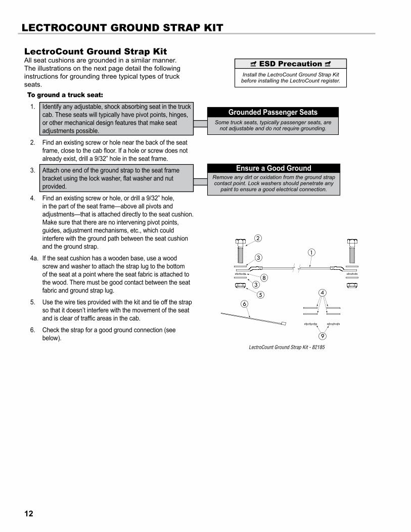
single stage systemsliquid Controls’ valves overviewWhen ordered as part of a meter system with a LCR-II, Liquid Control’s control valves are bolted onto the meter and wired to the LCR-II at the factory. Electronic control valves can also be ordered separately and retrofit onto meter systems already in service. These valves will need to be piped and wired in the field. For piping instructions, refer to the valve manual. This manual includes wiring instructions for the valves.
In order to control flow, the LCR-II energizes and de-energizes solenoid-operated valves on external bypass piping routed off the main product flow. The solenoid operated valves close off and open the bypass pipes. The bypass pipes redirect some of the product flow in order to open and close the control valve. These solenoid-operated valves must be wired to the LCR-II CPU board during installation.
Liquid Controls offers single stage and two stage electronic valves. Single stage valves have one solenoid valve (S1) and two positions—an open position and a closed position. Two stage valves have two solenoid valves (S1 & S2) and three positions—open, closed, and dwell flow. Dwell flow is a low flow rate setting controlled by the S2 solenoid and initiated shortly before the register reaches a preset value.
sInGle sTaGe valvesThe three most common Liquid Controls meter systems with single stage valves include a block valve with a S1 solenoid-operated valve fitted onto external piping (A2847-11), a block valve (A2843) with a 3-way solenoid, and an electro-pnuematic valve with an S1 solenoid.
A2847-11ValveThis single stage control valve has a S1 solenoid-operated valve located at the meeting point of three external pipes: one pipe from the inlet side of the valve, one from the top of the block valve, and one from the outlet side of the valve. This valve is typically used in refined fuels applications.
A2843Valveand3-WaySolenoidThe 3-way solenoid-operated valve—mounted directly to the top center port on the back of the LectroCount LCR-II—serves as a S1 solenoid-operated valve. The 3-way solenoid-operated valve is located at the meeting point of two pipes from the vapor eliminator (one for eliminated vapor and one leading to the spit tank) and one pipe to the top of the block valve. 3-way solenoid-operated valves are typically specified for products that hold vapor in the line such as LPG and NH3.
The LCR-II is also compatible with many other brands and types of valves.

20
valves
Two Stage 3-Way Valve with (S2) Block Valve
S1 Solenoid
E-7 Valve
S2 Solenoid
LectroCount LCR-II
Gallons
Two Stage (S1 and S2) E-7 Valve
S1 SolenoidS2 Solenoid
LectroCount LCR-II
Gallons
Two Stage (S1 and S2) Block Valve
Two stage systems
2
A2859-11 Solenoid-Operated
Block Valve and 3-Way Solenoid
E-7 Valve
A2848-11 Solenoid-Operated
Block Valve
TWo sTaGe valvesThe three most common Liquid Controls meter systems with two stage valves are: a block valve with a S1 and a S2 solenoid-operated valve fitted onto external piping (A2848-11), a block valve with a S2 solenoid-operated valve (A2859-11) and a 3-way solenoid on the LCR-II, and an E-7 valve with a S1 and a S2 solenoid-operated valve.
A2848-11ValveThis two stage control valve has a S1 and a S2 solenoid-operated valve. The S1 solenoid-operated valve is located at the meeting point of three bypass pipes: one pipe from the inlet side of the valve, one from the top of the block valve, and one from the outlet side of the valve. The S2 solenoid valve is located on a bypass pipe that connects the inlet and outlet sides of the control valve. It opens while the control valve is closed to supply the dwell flow. This valve is typically used in refined fuels applications.
A2859-11Valveand3-WaySolenoidA two stage valve with a S2 solenoid-operated valve and a 3-way solenoid valve attached to the back of the LectroCount LCR-II. The 3-way solenoid-operated valve is located at the meeting point of two pipes from the vapor eliminator (one for eliminated vapor and one leading to the spit tank) and one pipe to the top of the block valve. The S2 solenoid valve is located on a bypass pipe that connects the inlet and outlet sides of the control valve. It opens while the control valve is closed to supply the dwell flow. This configuration is typically specified for products that hold vapor in the line such as LPG and NH3.
E-7ValvesA two stage valve with a S1 and a S2 solenoid-operated valve. The E-7 valve is fitted with one external pipe to divert product flow to the closing mechanism. To supply a dwell flow, the E-7 redirects the product around the closed valve using channels molded into its housing. This valve is typically used in refined fuels applications.
single stage valves (cont.)
A2700SeriesElectro-PnuematicValveElectro-pnuematic valves use a S1 solenoid-operated valve mounted to a pneumatic actuator to open and close a V-7 valve. These valves are typically used in high viscosity applications like lube oil.

21
valves
Solenoid 1 Wiring for Single Stage Valves
Solenoid 1 and Solenoid 2 Wiring for A2859-11 and 3-Way Two Stage, 2848-11 Two Stage,
E7 Two Stage Wiring
valve Installation If installing the valve yourself, please refer to the valve’s installation and operation manual for mechanical installation. Instructions for wiring Liquid Controls valves to the LCR-II are on the following two pages.
Materials needed for wiring valves: not supplied with the valve• 20 AWG stranded wire (3 per solenoid). Not necessary for
3-Way solenoid valves. Only 2 needed for E7 solenoids.
• Weatherproof flexible conduit, ½" diameter and ½" NPT conduit connectors or cable glands
• PTFE tape or pipe sealant
To wire valves to the lCR-II:
1. Attach cable glands and/or conduit connectors to the solenoid valve(s) and the LCR-II port(s).
2. Thread the wires through piece of weatherproof conduit that is cut-to-length from the solenoid to a LCR-II port.
3. Run the weatherproof conduit between the solenoid-operated valve(s) and the LCR-II housing, pull the wires through the ports, and tighten the connectors.
4. Connect the S1 solenoid-operated valve wires to terminals 14 and 15 on the j13 terminal block of the LCR-II CPU board.
5. Connect the S2 solenoid-operated valve wires to terminals 17 and 18 on the j13 terminal block of the LCR-II CPU board.
To wire a single stage valves for presetting:
1. Wire the S1 solenoid as instructed above.
2. Run a jumper wire from Terminal 15 to Terminal 18.
Disconnect the power before working on the CPU board.
DisconnectPower
Solenoid operated valve 81527 (3-way LPG solenoid) has 3 cables potted into the housing. All other
solenoid operated valves on Liquid Controls valves use cable assembly 81859, which has 2 cables.
SolenoidOperatedValveCables
The Earth grounds for Terminals 16 & 19 are optional. The solenoid operated valves are grounded through
the component they are mounted on.
EarthGroundsforSolenoidValves

22
valves
valves WITh 110vaC solenoIdsIn order for the LectroCount LCR-II to control valves with solenoids on 110 VAC circuits, you must install a relay switch on the positive leg of the solenoid’s circuit.
Relay switch specifications:
Switch: SPST (single pole, single throw)SwitchPosition: Normally openContactRating: Greater than maximum current of solenoidVoltage: +12 VDC
Materials needed for wiring valves with 110 vaC solenoids: not supplied with the valve• SPST relay switch (1 per solenoid)
• 20 AWG stranded wire (2 per solenoid)
• Weatherproof flexible conduit, ½" diameter and ½" NPT conduit connectors or cable glands
• PTFE tape or pipe sealant
To wire 110 vaC solenoids to the lCR-II:
1. Turn off all 100 VAC circuits before beginning the installation.
2. Install the specified relay switch(es) onto one leg of the 110 solenoid power supply circuit.
3. Connect the relay switch on the S1 power supply circuit to terminals 15 and 16 on block j13.
4. Connect the relay switch on the S2 power supply circuit to terminals 17 and 18 on block j13.
Turn off all 110VAC circuits before beginning the installation.
DisconnectPower(110VAC)
23
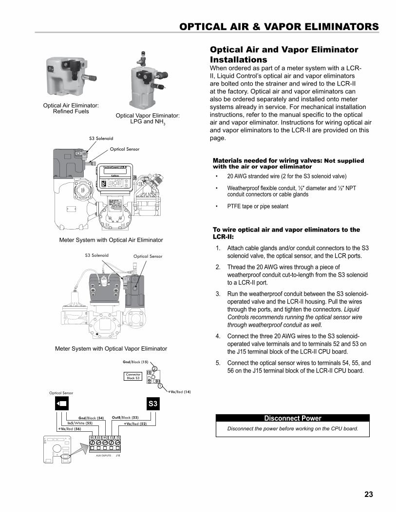
oPTICal aIR & vaPoR elIMInaToRs
Optical Air Eliminator: Refined Fuels
Optical Vapor Eliminator: LPG and NH3
S3
S3 Solenoid
Optical Sensor
LectroCount LCR-II
Gallons
Meter System with Optical Vapor Eliminator
Meter System with Optical Air Eliminator
optical air and vapor eliminator InstallationsWhen ordered as part of a meter system with a LCR-II, Liquid Control’s optical air and vapor eliminators are bolted onto the strainer and wired to the LCR-II at the factory. Optical air and vapor eliminators can also be ordered separately and installed onto meter systems already in service. For mechanical installation instructions, refer to the manual specific to the optical air and vapor eliminator. Instructions for wiring optical air and vapor eliminators to the LCR-II are provided on this page.
Materials needed for wiring valves: not supplied with the air or vapor eliminator• 20 AWG stranded wire (2 for the S3 solenoid valve)
• Weatherproof flexible conduit, ½" diameter and ½" NPT conduit connectors or cable glands
• PTFE tape or pipe sealant
To wire optical air and vapor eliminators to the lCR-II:
1. Attach cable glands and/or conduit connectors to the S3 solenoid valve, the optical sensor, and the LCR ports.
2. Thread the 20 AWG wires through a piece of weatherproof conduit cut-to-length from the S3 solenoid to a LCR-II port.
3. Run the weatherproof conduit between the S3 solenoid-operated valve and the LCR-II housing. Pull the wires through the ports, and tighten the connectors. Liquid Controls recommends running the optical sensor wire through weatherproof conduit as well.
4. Connect the three 20 AWG wires to the S3 solenoid-operated valve terminals and to terminals 52 and 53 on the j15 terminal block of the LCR-II CPU board.
5. Connect the optical sensor wires to terminals 54, 55, and 56 on the j15 terminal block of the LCR-II CPU board.
Disconnect the power before working on the CPU board.
DisconnectPower

24
PUlse oUTPUT devICe (Pod)
Pulse Output Device (POD)
Port
LectroCount LCR-II
Gallons
Meter System with Pulse Output Device
Pulse output device (Pod) InstallationWhen ordered as part of a meter system with a LCR-II, Liquid Control’s Pulse Output Device (POD) is installed onto the meter and wired to the LCR-II at the factory. The POD can also be ordered separately and installed onto meter systems already in service. For mechanical installation instructions, refer to the POD manual. Instructions for wiring the POD to the LCR-II are provided on this page.
Materials needed for wiring valves: not supplied with the Pod• 22 AWG stranded wire (4)
• Weatherproof flexible conduit, ½" diameter and ½" NPT conduit connectors or cable glands
• PTFE tape or pipe sealant
To wire a Pod to the lCR-II:
1. Attach cable glands and/or conduit connectors to the POD and the LCR-II port(s).
2. Thread the wires through a piece of weatherproof conduit cut-to-length from the POD port to a LCR-II port.
3. Run the weatherproof conduit between the POD and the LCR-II housing, pull the wires through the ports, and tighten the connectors.
4. Connect the four POD terminals to four terminals on the j18 terminal block of the LCR-II CPU board.
• POD terminal 20 to LCR-II terminal 31 • POD terminal 21 to LCR-II terminal 34 • POD terminal 22 to LCR-II terminal 33 • POD terminal 23 to LCR-II terminal 37
single Channel Pulse InputsThe LCR-II is compatible with the many single channel pulsers and amplifiers, for example, the SP714 pulse amplifier.
To a single channel pulse output to the lCR-II
1. Slide the jumper over pins 2 & 3 (counting down from the top) of j17. The jumper fits over the pins and under the plastic casing.
3. Wire the single channel pulser to the j8 terminal of the 81920 CPU board. Schematic on the right shows wiring to a Sponsler SP714.
Disconnect the power before working on the CPU board.
DisconnectPower
This wiring schematic applies to pulse output devices 1 through 4 only.
PulseOutputDevices1,2,3,&4Only

25
dIffeRenTIal PRessURe (∆P) TRansdUCeR
differential Pressure (∆P) Transducer InstallationWhen ordered as part of a meter system with a LCR-II, Liquid Control’s ∆P transducer is wired to the LCR-II at the factory. The ∆P transducer can also be ordered separately and installed onto a meter system already in service. Refer to the ∆P transducer manual for complete installation instructions. Instructions for wiring the ∆P transducer to the LCR-II are provided on this page.
The ∆P Transducer requires an additional board (PN 81944) that mounts directly to the LCR-II CPU board. Typically, a ∆P transducer operates in conjuction with a shutdown device, such as a valve or a dead-man. The shutdown control must be wired to the LCR-II and should draw no more than 1 A.
To wire ∆P Transducer to the lCR-II:
1. Unplug the j1, j2, and j3 terminal blocks from the LCR-II CPU board. Leave the wires in the terminals.
2. Remove the screw at the top left corner of the LCR-II CPU board.
3. Plug the 81944 board into the j1 connectors on the LCR-II CPU board.
4. Fasten the top left side of both boards to the housing with the screw provided.
5. Plug terminal block j1 into the 81944 board. Plug j2 and j3 back into the LCR-II CPU board
6. Plug terminal j16 into the 81944 board.
7. Route the ∆P transducer cable through a cable gland in a port on the back of the LCR-II. Secure the cable gland. LC recommends running the cable through weatherproof conduit.
8. Connect the four ∆P transducer wires to terminals j3 on the LCR-II CPU board and j16 on the 81944 board.
• Black to j3 terminal 46 • White to j3 terminal 51 • Yellow to j16 terminal 57 • Blue to j16 terminal 58 • Red to j16 terminal 59
9. Run the red jumper wire (provided with the ∆P transducer kit) from the j8 terminal 32 to j16 terminal 59 (+5 V).
10. Route a two wire cable from the shutdown control device through a cable gland in a port on the back of the LCR-II. Secure the cable gland. LC recommends running the cable through weatherproof conduit.
11. Connect the two wires from the shutdown control device to terminal block j13, terminals 14 and 15.
The shutdown device should draw no more than 1 A.
When removing the J1 or J16
terminal from the 81944 board, hold
down the right end of the main CPU board to
prevent flexing.
BeCarefulwiththeCPUBoard
111213
PRINTER SERIAL 485 TERMINAL
POWER
COUNTER
MH1 CTS RXD TXD RTS GNDGND 485+A485-B CTS RXD TXD RTS +VP
EART
H
GND
GND
IN 1
IN 2
IN 3
IN 4
+5V
OUT
+VP
GND +12-
24V
MH4
J20
J6
J3J2J1
J7J7
C2
2425
∆P Transducer
+5V(Out)/Jumper (59 to 32)A/Blue (58)
+5V/Red (59)
B/Yellow (57)
GND/White (51)
+VP/Black (46)
B

26
ReMoTe dIsPlay and aUxIlIaRy oUTPUTs
auxiliary outputsThe LCR-II provides three open drain transistor auxiliary outputs for different external devices such as pump controls and additive injectors. The schematic to the right identifies the j13 terminals where the auxiliary outputs can be connected to the LCR-II.
AuxiliaryOutput1(Out1)This signal has four output settings: Off, On, On During Delivery, and Monitor Flowrate.
AuxiliaryOutput2(Out2)This signal has three output settings: Off, On, On During Delivery, and Flow Direction.
PulseOutput(Out3)This output represents the gross delivery quantity for uncompensated deliveries or the net delivery quantity (for compensated deliveries). This output is a real time 50/50 duty cycle representing the least significant digit of the LCR-II totalizers.
auxiliary outputs 4 & 5 (lectroCount Remote display)Auxiliary ouputs 4 & 5 are typically used for the 2¼" E1610 Large Remote Display, but they can also be used with other types of displays. Signals from these outputs duplicate the volume data sent to the LCR-II display. Refer to the LectroCount remote display manual for complete installation instructions.
To wire the 2¼" e1610 large Remote display to the lCR-II:
1. Attach cable glands and/or conduit connectors to the display and the LCR-II port(s).
2. Thread the wires through a piece of weatherproof conduit cut-to-length from the display port to a LCR-II port.
3. Run the weatherproof conduit between the display and the LCR-II housing, pull the wires through the ports, and tighten the connectors.
4. Connect the four display terminals to four terminals on the j18 terminal block of the LCR-II CPU board.
• Remote display terminal 20 to LCR-II terminal 45 • Remote display terminal 21 to LCR-II terminal 39 • Remote display terminal 22 to LCR-II terminal 40 • Remote display terminal 23 to LCR-II terminal 41
To select the Auxiliary Output settings, refer to the LectroCount LCR-II Setup and Operation manual.
Disconnect the power before working on the CPU board.
DisconnectPower
27
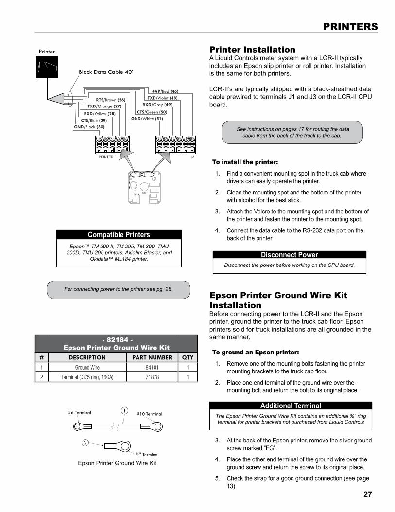
Printer InstallationA Liquid Controls meter system with a LCR-II typically includes an Epson slip printer or roll printer. Installation is the same for both printers.
LCR-II’s are typically shipped with a black-sheathed data cable prewired to terminals j1 and j3 on the LCR-II CPU board.
To install the printer:
1. Find a convenient mounting spot in the truck cab where drivers can easily operate the printer.
2. Clean the mounting spot and the bottom of the printer with alcohol for the best stick.
3. Attach the Velcro to the mounting spot and the bottom of the printer and fasten the printer to the mounting spot.
4. Connect the data cable to the RS-232 data port on the back of the printer.
PRInTeRs
Disconnect the power before working on the CPU board.
DisconnectPowerEpson™ TM 290 II, TM 295, TM 300, TMU
200D, TMU 295 printers, Axiohm Blaster, and Okidata™ ML184 printer.
CompatiblePrinters
For connecting power to the printer see pg. 28.
See instructions on pages 17 for routing the data cable from the back of the truck to the cab.
epson Printer Ground Wire Kit InstallationBefore connecting power to the LCR-II and the Epson printer, ground the printer to the truck cab floor. Epson printers sold for truck installations are all grounded in the same manner.
To ground an epson printer:
1. Remove one of the mounting bolts fastening the printer mounting brackets to the truck cab floor.
2. Place one end terminal of the ground wire over the mounting bolt and return the bolt to its original place.
3. At the back of the Epson printer, remove the silver ground screw marked “FG”.
4. Place the other end terminal of the ground wire over the ground screw and return the screw to its original place.
5. Check the strap for a good ground connection (see page 13).
The Epson Printer Ground Wire Kit contains an additional ⅜" ring terminal for printer brackets not purchased from Liquid Controls
AdditionalTerminal
- 82184 - epson Printer Ground Wire Kit
# Description part number Qty
1 Ground Wire 84101 1
2 Terminal (.375 ring, 16GA) 71878 1
1#6 Terminal #10 Terminal
³⁄₈" Terminal
2
Epson Printer Ground Wire Kit

28
PoWeR InsTallaTIon
Power Installation overview When you have made all of the data connections and finished installing all of the components, connect the power to the LCR-II and the Epson printer. But before making the power connections, go through the vehicle system checklist below, and ensure that the electrical system of the truck meets the minimum requirements for powering the LCR-II and the Epson printer.
vehicle system Checklist
Clean any corrosion from the battery terminals and battery cable to guarantee a solid, tight connection.
Charge the battery in accordance with the manufacturer’s specifications.
Ensure the alternator is large enough to meet the total demands of the truck, including the LCR-II. The LCR-II requires a minimum of 5 A for proper operation. Run the truck at low idle with all accessories on (including hose reel), and check the voltage with a multi-meter. The voltage should not drop below 11 V.
Inspect the electrical equipment on the vehicle, and ensure it is properly installed and operating correctly.
Determine whether the vehicle is grounded positively or negatively. Consult Liquid Controls if the vehicle has a positive ground.
Make sure that any radio antennas are installed in accordance with the manufacturer’s specification to prevent RF interference.
Connect the PowerAll LCR-II shipments typically include a 40' gray power cable (100', and 300' are also available) and a 7.5A fuse.
40’ GRay PoWeR Cable The gray power cable (PN 84046) is prewired to the j6 terminal on the CPU board at the factory. It includes two 16AWG wires and a ground drain wire. The 7.5A fuse should be spliced into the red 16AWG wire as close to the power source as possible.
ePson PRInTeR PoWeRPower must be supplied to the Epson printer as well. A 15' cable with a 12/24VDC converter (825001) for printer power supply is also available. The red wire of this cable must be spliced into the red wire of the gray power cable on the LCR-II side of the 7.5A fuse.
To connect power to the lCR-II and the epson printer:
1. Route the gray power cable to the accessory panel. See page 17.
2. Splice the red wire from the printer power cable into the red wire of the gray power cable.
3. Splice the 7.5A fuse into the red wire. Make the splice close to the direct power terminal connection in the accessory panel and on the power side of the splice made with the printer power cable.
4. Connect the red wire to the direct power supply terminal in the accessory panel.
5. Connect the black wire of the gray power cable to a reliable DC ground.
6. Connect the black wire of the printer power to a reliable DC ground.
7. Tape the green drain wire of the gray power cable back against the power cable.
Page 17 describes the best practices for routing the gray power cable to the truck cab’s accessory panel.

29
Power CheckAfter the LCR-II has been installed, check to make sure that it powers up correctly. The LCR-II display and the printer power light should come on when the truck’s ignition is turned to the ON or to the ACC position. Make sure the printer power switch is on. If the LCR-II or the printer does not power up, check the wiring and the connections on the LCR-II CPU board against the manual.
PoWeR InsTallaTIon
epson Printer Power Connections
lectroCount lCR-II Power Connections

30
Close and seal the UnitOnce the unit has been setup and tested, finish the installation by closing and sealing the housing. The LCR-II must be environmentally sealed to protect the electronics against the elements. The LCR-II must also be sealed by a Weights & Measures representative to guarantee the register is operating at the proper regulatory standards.
1. Secure the cables behind the LCR-II and the cables in the cab with cable ties.
2. If conduit was used during the installation, fill the conduit end inside the LCR-II with silicon RTV (provided with shipment, PN 82575). ReadandfollowthedirectionsoftheEnvironmentalSealingGuidelinesbelow.
3. Tighten the cover bolt using a large flat-tip screwdriver or a 7/16” socket. Completely close the gap between the cover and the housing tab. ReadandfollowthedirectionsoftheEnvironmentalSealingGuidelinesbelow.
4. Seal the cover bolt and the switch plate bolts with a wire/lead seal.SeeWeights&MeasuresSealsonpg.31.
After the LCR-II is powered correctly, continue on to the LectroCount LCR-II Setup and Operation manual to setup the LCR-II for operation. You will want to setup and test the LCR-II before closing and sealing the unit.
IMPoRTanT: before sealing the lCR-II
PosT InsTallaTIon
31
environmental sealing GuidelinesThe LCR-II includes sensitive electronic components, including a micro-controller that can be damaged by the presence of moisture. Therefore, it is essential that all conduit ports, the cover, and the shaft seals be adequately sealed by the installer to ensure watertight integrity. The conformal coating on the board and a moisture-absorbing desiccant inside the enclosure mitigates the problem of corrosion due to moisture, but these measures only protect the board from small amounts of moisture trapped inside when the lid is closed in humid conditions. They are not adequate in protecting the unit over time if a continuous leak is present in the enclosure.
1. ConduitEntrances The LCR-II housing has seven conduit entrances, five ½" NPT female threads and two ¾" NPT. Use only ½" or ¾" NPT male
threaded fittings on the conduit entrances. Pressed in Caplugs and straight (rather than tapered) threads are inadequate as seals for these entrances. Acceptable fittings are either metal or plastic conduit, pipe plugs, or cable glands. Threads should be treated with PTFE-based “pipe dope” or a minimum of two revolutions of PTFE tape prior to installation. Threads should be engaged a minimum of four full turns. When using cable glands, be sure the gland is sized properly for the outside diameter of the cable and the elastometric seal around the cable sheath is compressed onto the cable. Use only one cable per cable gland unless the gland is designed for multiple cables. When using conduit or Liquid-Tite, make sure that the opposite end is connected to an environmentally sealed device. If the conduit is not sealed at the other device, fill the interior of the conduit at the LCR-II with a silicone rubber sealant, such as RTV, to prevent moisture from running down the conduit into the enclosure.
2. CoverSeals To seal the LCR-II cover properly, ensure that the O-ring surrounding the cover is fit snug inside the groove, and tighten the
cover screw securely.3. ShaftSeals Units with internal pulsers have an O-ring around the pulse encoder drive shaft that extends through the bottom of the LCR
housing. If a drive shaft adapter was attached at installation, make sure the O-ring around the shaft is securely seated in the counter bore of the casting, covered with the flat washer provided, and held in place with the cotter pin provided. The control switch on the front of the LCR-II is also sealed with an O-ring and held in place by a bushing secured with three socket head cap screws. When replacing a control switch in the field, make sure the O-ring is in place on the switch shaft before reinstalling the switch bushing.
Any water or moisture damage to the LCR-II as result of improper sealing will not be covered under the product warranty.
SealingtheLCR-IIistheResponsibilityoftheInstaller
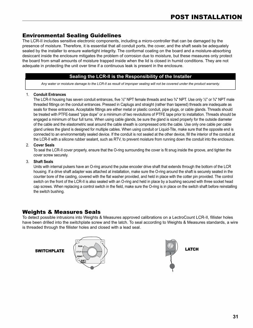
Weights & Measures sealsTo detect possible intrusions into Weights & Measures approved calibrations on a LectroCount LCR-II, fillister holes have been drilled into the switchplate screw and the latch. To seal according to Weights & Measures standards, a wire is threaded through the fillister holes and closed with a lead seal.
sWITChPlaTe laTCh
PosT InsTallaTIon
32
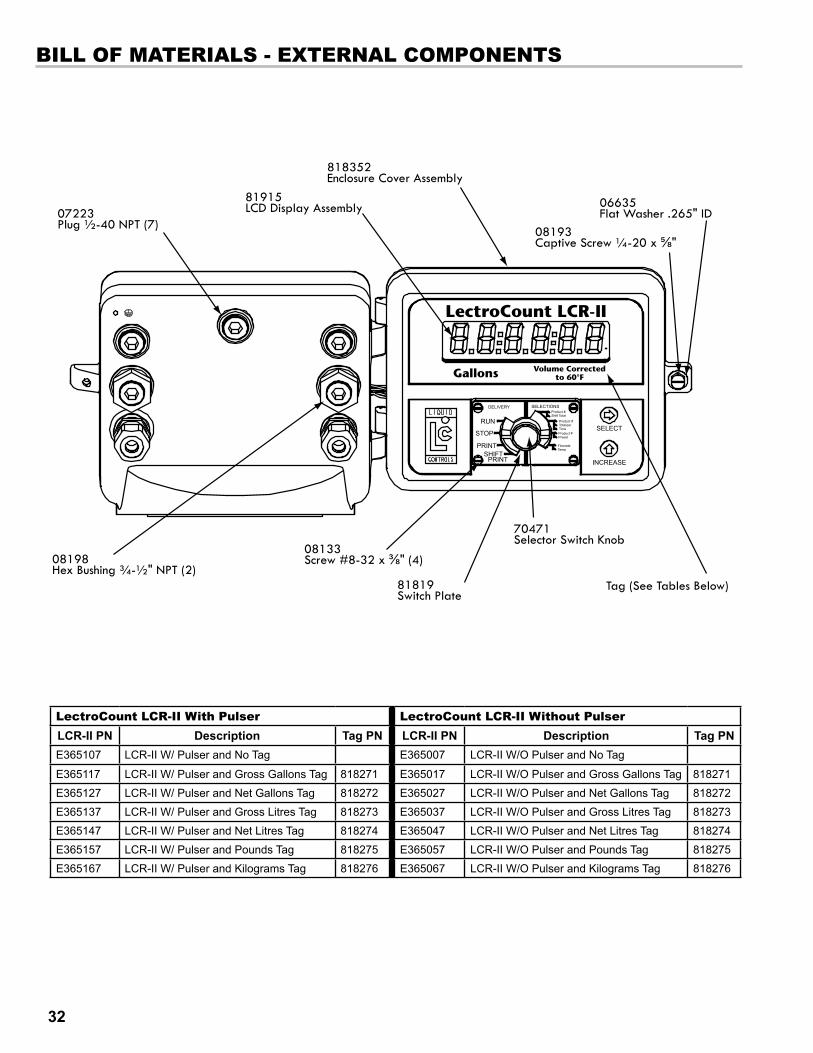
bIll of MaTeRIals - exTeRnal CoMPonenTs
lectroCount lCR-II With Pulser lectroCount lCR-II Without PulserLCR-IIPN Description TagPN LCR-IIPN Description TagPNE365107 LCR-II W/ Pulser and No Tag E365007 LCR-II W/O Pulser and No Tag
E365117 LCR-II W/ Pulser and Gross Gallons Tag 818271 E365017 LCR-II W/O Pulser and Gross Gallons Tag 818271
E365127 LCR-II W/ Pulser and Net Gallons Tag 818272 E365027 LCR-II W/O Pulser and Net Gallons Tag 818272
E365137 LCR-II W/ Pulser and Gross Litres Tag 818273 E365037 LCR-II W/O Pulser and Gross Litres Tag 818273
E365147 LCR-II W/ Pulser and Net Litres Tag 818274 E365047 LCR-II W/O Pulser and Net Litres Tag 818274
E365157 LCR-II W/ Pulser and Pounds Tag 818275 E365057 LCR-II W/O Pulser and Pounds Tag 818275
E365167 LCR-II W/ Pulser and Kilograms Tag 818276 E365067 LCR-II W/O Pulser and Kilograms Tag 818276
08198Hex Bushing ¾-½" NPT (2)
07223Plug ½-40 NPT (7)
81915LCD Display Assembly
818352Enclosure Cover Assembly
06635Flat Washer .265" ID
08193Captive Screw ¼-20 x ⅝"
08133Screw #8-32 x ⅜" (4)
81819Switch Plate
70471Selector Switch Knob
Tag (See Tables Below)
LectroCount LCR-II
Gallons Volume Correctedto 60°F

33
bIll of MaTeRIals - InTeRnal CoMPonenTs
optional Items (not shown)
description Part numberPrinter Extension Cable 71237
Flash Cable 81885Lap Pad Adapter 81514
Lap Pad E40301Lap Pad with Adapter E403012
This manual applies to LCR-II’s with 81920 and 81547-2 CPU boards only.
If your LCR-II has a 84040 CPU board, please refer to the EM150-11 LectroCount LCR-II (E3655/E3656 Series) Installation Manual. The 84040 board is blue. Calibration tickets from 84040 boards will have a “SR26x” in the FIRMWARE field instead of the “SR21x” of 81920 and 81547-2 boards.
PN. 82597: Pulser Field Install Kit
PN. 08201: O-Ring (2)
Cotter Pin
PN. 08189: Flat Washer
Pulser, 100 PPR
PN. 81833: Hollow O-Ring Seal
PN. 81330: Cable, Coiled Handset
PN. 81839: Membrane Switch Harness Assembly
PN. 81832: Rotary Switch & Harness Assembly
PN. 81836: Ground Strap (1) w/ Screw & Washer (2)
PN. 81513040: Cable Assembly Lap Pad & Printer
PN. 81512: Cable Assembly Power Input
PN. 71319: Desiccant
PN. 81840: Enclosure, Base Assembly w/o PulserPN. 81841: Enclosure, Base Assembly w/ Pulser
PN. 08158: Screw, #6-32 x 1/2” (4)
PN. 07677: Ground Screw, #8-32 x 1/4”
PN. 81547-2: PC Board Assemblyor PN. 81920: PC Board Assembly
PN. 08209: O-RingPN. 09380: Nylon Washer (2)

34
bIll of MaTeRIals - CPU boaRds
81324J1–5-Pin Connector
81323J2–2-Pin Connector 81456
J3–6-Pin Connector
81320J6–3-Pin Connector
81392J8–8-Pin Connector
81391J12–7-Pin Connector
81321J13–6-Pin Connector81322
J14–4-Pin Connector
81324J1–5-Pin Connector
81323J2–2-Pin Connector
81456J3–6-Pin Connector
81320J6–3-Pin Connector
81392J8–8-Pin Connector
81391J12–7-Pin Connector
81321J13–6-Pin Connector
81837J15–5-Pin Connector
81322J14–4-Pin Connector
81920 CPU board
81547-2 CPU board
81547-2 is obsolete. CPU board shown here for maintenance reference


Wiring TablesThis appendix provides a tabular description of the wiring connections made to each LCR-II terminal block. It should be referenced in the event wiring is inadvertently mis-routed in the field, or for general troubleshooting in the event of a problem.
Jumper J10 on LCR-II circuit board must be set for RS-232 communication protocol.
* For a standard RS-232 terminal (other than the Lap Pad), the red wire is connected to J3-47.
Jumper J10 on LCR circuit board must be set for RS-485 communication protocol.
The drain wire must be connected to Pin 13 of terminal J6 in the LCR-II. It must not be connected in the cab. Trim the drain wire from the cable end in the cab.
The LCR-II Power cable kit includes a fuse holder and fuse to protect the system in the event of a short circuit in the cable. Liquid Controls recommends that this fuse be used in all installations not having a fused accessory block to protect the truck in the event of cable faults.
PRInTeR ConneCTIon (j1)
Terminal Pin signalWire Color Cable
#81513Route To
J1-30 GND Black Printer, Pin 729 CTS Blue Printer, Pin 2028 RXD Yellow Printer, Pin 227 TXD Orange Printer, Pin 326 RTS Brown Printer, Pin 6
PoWeR ConneCTIon (j6)Terminal Pin signal Wire Color Route To
J6-13 Earth Drain/Green Wire No Connection12 GND Black DC Ground
11 +12V In or +24V In Red +12VDC or
+24VDC
PRInTeR ConneCTIon (j1)Terminal
Pin signal Wire Color Cable #81513 Route To
J3-51 GND White Ground, Pin 550 CTS Green RTS Terminal, Pin 449 RXD Gray TXD Terminal, Pin 348 TXD Violet TXD Terminal, Pin 247 RTS * CTS Terminal, Pin 846 +Vo Red Lap Pad +12, Pin 8
fRonT CoveR PUsh bUTTons &InTeRnal PUlseR ConneCTIon (j8)
Terminal Pin signal Wire Color
Cable #81513 Route To
J8-38 GND Black Internal Pulser GND37 GND Black Push Button GND36 In 1 Violet INCREASE Button35 In 2 Gray SELECT Button34 In 3 Green Int. Pulser “B”33 In 4 White Int. Pulser “A”32 +5V Out Red Int. Pulser “+”31 +Vo
lIQUId ConTRols Pod (j8)Terminal
Pin signal Wire Color Cable #81513 Route To
J8-3837 GND Black Pulser Signal GND363534 In 3 Green Channel B Output33 In 4 White Channel A Output3231 +Vo Red +V Input
TeRMInal ConneCTIon Rs-485 (j2)Terminal
Pin signalWire Color Route
ToCable #81572 Cable #81513
J2-25 485-B Black Violet Terminal24 485+A Red Red Terminal
36
Appendix

Wiring TablesThis appendix provides a tabular description of the wiring connections made to each LCR-II terminal block. It should be referenced in the event wiring is inadvertently mis-routed in the field, or for general troubleshooting in the event of a problem.
Pull-down resistors of 300 Ω needs to be connected between CHAN B and GND, and CHAN A and GND.
To operate a single channel pulser, a jumper is required between pins 2 and 3 on J4.
sInGle Channel PUlseR (j8)Terminal
Pin signal Wire Color Route To
J8-3837 GND N/A Pulser Signal GND36353433 In 4 N/A Pulse Output3231 +Vo Red +V Input
veedeR RooT solId sTaTe QUad PUlseR (j8)
Terminal Pin signal Wire Color Route To
J8-3837 GND White Pulser Signal GND363534 In 3 Orange Channel B Output33 In 4 Black Channel A Output3231 +Vo Red +V Input
aUxIlIaRy oUTPUTs (j12)Terminal
Pin signal Wire Color Route To
J12-45 +Vo N/A
44 Out 1 Aux. 1 N/A Pump or Aux. Control
43 Out 2 Aux. 2 N/A Flow Direction
42 Out 3 N/A Pulse Input for Aux. System
41 GND N/A40 Out 4 N/A Display Input39 Out 5 N/A Display Input
valve solenoId ConneCTIon (j13)Terminal
Pin signal Wire Color Route To
J13-19 Earth Green Solenoid 2 Case Ground
18 Out 6 Black or Red Solenoid 217 +Vo Black or Red Solenoid 2
16 Earth Green Solenoid 1 Case Ground
15 Out 7 Black or Red Solenoid 114 +Vo Black or Red Solenoid 1
RTd TeMP. PRobe ConneCTIon (j14)Terminal
Pin signal Wire Color Route To
J14-23 RTD-D Red RTD22 RTD-S Red RTD21 RTD+D White RTD20 RTD+S White RTD
oPTICal aIR elIMInaToR (j15)Terminal
Pin signal Wire Color Route To
J15-56 +Vo Red Optical Sensor55 In 5 White Optical Sensor54 GND Black Optical Sensor53 Out 8 Black Solenoid 352 +Vo Red Solenoid 3
37
Appendix

Lap Pad Connection
setup and lap PadBefore the LCR-II the register can be setup and calibrated, the initial settings must be entered. To do this, you will need to use a lap pad. The lap pad is connects to a 9-pin female connector on a lap pad adapter. The lap pad adapter connects to the printer and data cable.
Instructions for the setup and calibration of the LCR-II are in manual EM100-11, LectroCount LCR-II Setup & Operation.
obsolete Products - e1600x2 1" large Remote display Auxiliary ouputs 4 & 5 can also be used for the, now obsolete, E1600X2 1” Large Remote Display.
To wire an e1600x2 1" large Remote display to the lCR-II:
1. Attach cable glands and/or conduit connectors to the display and the LCR-II port(s).
2. Thread the wires through a piece of weatherproof conduit cut-to-length from the display port to a LCR-II port.
3. Run the weatherproof conduit between the display and the LCR-II housing, pull the wires through the ports, and tighten the connectors.
4. Connect the four display terminals to four terminals on the j18 terminal block of the LCR-II CPU board.
• Remote display terminal 20 to LCR-II terminal 39 • Remote display terminal 21 to LCR-II terminal 45 • Remote display terminal 22 to LCR-II terminal 40 • Remote display terminal 23 to LCR-II terminal 41
LapPadDataCommunicationTo operate the lap pad, terminal j10 must have the
jumper in the RS-232 position.
38
Appendix

obsolete Products - hand held ComputerThe hand held computer is connected to the LCR-II through the RS-485 port. For this reason, an extra cable must be run from the register (j2) to the Power Supply unit installed in the truck cab. For more detailed information on the setup and operation of the hand held computer, refer to publication number 500096.
To connect the lCR-II to the hand held Computer:
1. With the power to the LCR-II OFF, move the j10 jumper to the RS-485 position on the LCR-II board.
2. Connect the two-conductor RS-485 data cable to connector j2 on the LCR-II board. Run the other end of the data cable to the front side of the power supply.
3. Connect the LCR-II power cable to the front side of the power supply in the cab.
4. Run the LCR-II printer cable to the cab and connect directly into the back of the printer.
5. Connect the main power supply cable to the power supply. Connect the other end to the fuse panel on an accessories circuit.
6. Connect the coiled cable provided to the bottom connection of the hand held computer. Connect the other end of the cable to the back side of the power supply.
7. Connect the printer power cable to the back of the printer. Connect the other end of this cable to the front side of the power supply.
39
Appendix

©2006LiquidControlsPub.No.500301
(12/2012)
105 Albrecht DriveLake Bluff, IL 60044-22421.800.458.5262 • 847.295.1050Fax: 847.295.1057www.lcmeter.com
TopTech SySTemS1124 Florida Central ParkwayLongwood, FL 32750(407) 332-1774
Nateus Business ParkNieuwe Weg 1-Haven 1053B-2070 Zwijndrecht (Antwerp), Belguim+32 (0)3 250 60 60
Liquid conTroLS105 Albrecht DriveLake Bluff, IL 60044(847) 295-1050
Liquid conTroLS europe/SAmpiVia Amerigo Vespucci 155011 Altopascio (Lucca), Italy+39 0583 24751
ideX FLuid And meTering pvT. LTd.Survey No. 256, AlindraSavli GIDC, ManjusarDist. Vadodara 391 770Gujarat, India+91 265 2631855
Liquid conTroLS SponSLer105 Albrecht DriveLake Bluff, IL 60044(847) 295-1050
FAure hermAnRoute de Bonnetable B.P. 2015472406 La Ferté-Bernard Cedex, France+33 (0)2 43 60 28 60
6961 Brookhollow West DriveHouston, TX 77040(713) 623-0808
corken3805 Northwest 36th St.Oklahoma City, OK 73112(405) 946-5576