Embed Size (px)
Citation preview

Galaxy 30010–40 kVA 3:1 and 3:3
Installation
380/400/415 V
01/2016
www.schneider-electric.com

Legal InformationThe Schneider Electric brand and any registered trademarks of Schneider ElectricIndustries SAS referred to in this guide are the sole property of Schneider ElectricSA and its subsidiaries. They may not be used for any purpose without the owner'spermission, given in writing. This guide and its content are protected, within themeaning of the French intellectual property code (Code de la propriétéintellectuelle français, referred to hereafter as "the Code"), under the laws ofcopyright covering texts, drawings and models, as well as by trademark law. Youagree not to reproduce, other than for your own personal, noncommercial use asdefined in the Code, all or part of this guide on any medium whatsoever withoutSchneider Electric's permission, given in writing. You also agree not to establishany hypertext links to this guide or its content. Schneider Electric does not grantany right or license for the personal and noncommercial use of the guide or itscontent, except for a non-exclusive license to consult it on an "as is" basis, at yourown risk. All other rights are reserved.
Electrical equipment should be installed, operated, serviced, and maintained onlyby qualified personnel. No responsibility is assumed by Schneider Electric for anyconsequences arising out of the use of this material.
As standards, specifications, and designs change from time to time, please ask forconfirmation of the information given in this publication.
10–40 kVA 3:1 and 3:3
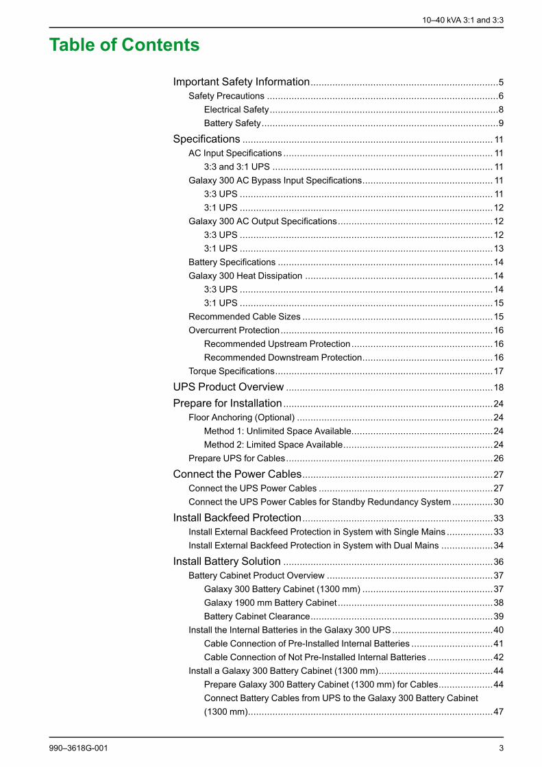
Table of Contents
Important Safety Information.....................................................................5Safety Precautions .....................................................................................6
Electrical Safety....................................................................................8Battery Safety.......................................................................................9
Specifications ............................................................................................ 11AC Input Specifications ............................................................................. 11
3:3 and 3:1 UPS ................................................................................. 11Galaxy 300 AC Bypass Input Specifications................................................ 11
3:3 UPS ............................................................................................. 113:1 UPS .............................................................................................12
Galaxy 300 AC Output Specifications.........................................................123:3 UPS .............................................................................................123:1 UPS .............................................................................................13
Battery Specifications ...............................................................................14Galaxy 300 Heat Dissipation .....................................................................14
3:3 UPS .............................................................................................143:1 UPS .............................................................................................15
Recommended Cable Sizes ......................................................................15Overcurrent Protection..............................................................................16
Recommended Upstream Protection....................................................16Recommended Downstream Protection................................................16
Torque Specifications................................................................................17
UPS Product Overview ............................................................................18
Prepare for Installation .............................................................................24Floor Anchoring (Optional) ........................................................................24
Method 1: Unlimited Space Available....................................................24Method 2: Limited Space Available.......................................................24
Prepare UPS for Cables............................................................................26
Connect the Power Cables......................................................................27Connect the UPS Power Cables ................................................................27Connect the UPS Power Cables for Standby Redundancy System...............30
Install Backfeed Protection......................................................................33Install External Backfeed Protection in System with Single Mains .................33Install External Backfeed Protection in System with Dual Mains ...................34
Install Battery Solution .............................................................................36Battery Cabinet Product Overview .............................................................37
Galaxy 300 Battery Cabinet (1300 mm) ................................................37Galaxy 1900 mm Battery Cabinet .........................................................38Battery Cabinet Clearance...................................................................39
Install the Internal Batteries in the Galaxy 300 UPS.....................................40Cable Connection of Pre-Installed Internal Batteries ..............................41Cable Connection of Not Pre-Installed Internal Batteries ........................42
Install a Galaxy 300 Battery Cabinet (1300 mm)..........................................44Prepare Galaxy 300 Battery Cabinet (1300 mm) for Cables....................44Connect Battery Cables from UPS to the Galaxy 300 Battery Cabinet(1300 mm)..........................................................................................47
990–3618G-001 3

10–40 kVA 3:1 and 3:3
Connect External Battery Temperature (ATIZ) and External BatteryBreaker Signal between the UPS and the Galaxy 300 Battery Cabinet(1300 mm)..........................................................................................48Connect Battery and Signal Cables from the Galaxy 300 BatteryCabinet (1300 mm) to a Running UPS ..................................................50
Install a Galaxy 1900 mm Battery Cabinet ..................................................53Prepare Galaxy 1900 mm Battery Cabinet for Cables ............................53Connect Battery Cables from the UPS to the Galaxy 1900 mm BatteryCabinet ..............................................................................................56Install External Battery Temperature (ATIZ) and External BatteryBreaker Signal between the UPS and the Galaxy 1900 mm BatteryCabinet ..............................................................................................57
Connect Battery and Signal Cables to Third Party Battery Solution...............60
Connect the UPS Signal Cables.............................................................63Connect the Signal Cables to the UPS .......................................................63Connect the EPO Cable to the UPS ...........................................................65Connect the Optional Signal Cables...........................................................67
Checklist after Installation........................................................................68
4 990–3618G-001
Important Safety Information 10–40 kVA 3:1 and 3:3
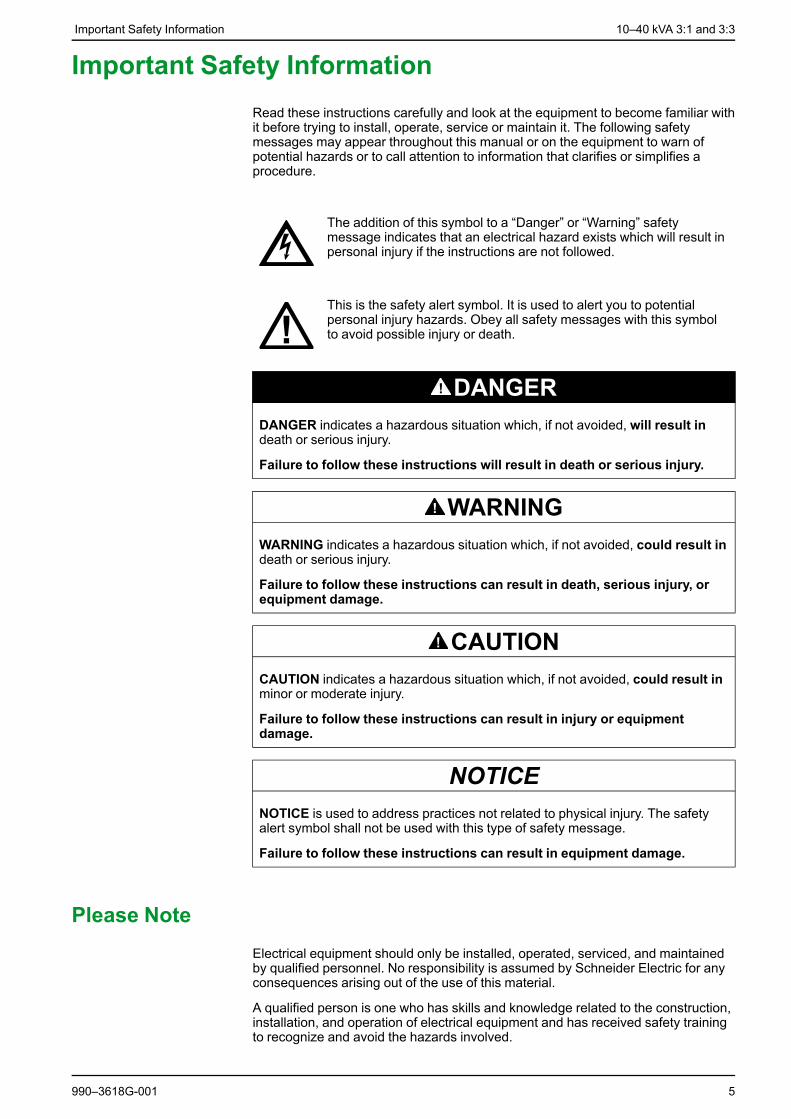
Important Safety InformationRead these instructions carefully and look at the equipment to become familiar withit before trying to install, operate, service or maintain it. The following safetymessages may appear throughout this manual or on the equipment to warn ofpotential hazards or to call attention to information that clarifies or simplifies aprocedure.
The addition of this symbol to a “Danger” or “Warning” safetymessage indicates that an electrical hazard exists which will result inpersonal injury if the instructions are not followed.
This is the safety alert symbol. It is used to alert you to potentialpersonal injury hazards. Obey all safety messages with this symbolto avoid possible injury or death.
DANGERDANGER indicates a hazardous situation which, if not avoided, will result indeath or serious injury.
Failure to follow these instructions will result in death or serious injury.
WARNINGWARNING indicates a hazardous situation which, if not avoided, could result indeath or serious injury.
Failure to follow these instructions can result in death, serious injury, orequipment damage.
CAUTIONCAUTION indicates a hazardous situation which, if not avoided, could result inminor or moderate injury.
Failure to follow these instructions can result in injury or equipmentdamage.
NOTICENOTICE is used to address practices not related to physical injury. The safetyalert symbol shall not be used with this type of safety message.
Failure to follow these instructions can result in equipment damage.
Please NoteElectrical equipment should only be installed, operated, serviced, and maintainedby qualified personnel. No responsibility is assumed by Schneider Electric for anyconsequences arising out of the use of this material.
A qualified person is one who has skills and knowledge related to the construction,installation, and operation of electrical equipment and has received safety trainingto recognize and avoid the hazards involved.
990–3618G-001 5

10–40 kVA 3:1 and 3:3 Important Safety Information
Safety Precautions
DANGERHAZARD OF ELECTRIC SHOCK, EXPLOSION, OR ARC FLASH
All safety instructions in this document must be read, understood and followed.
Failure to follow these instructions will result in death or serious injury.
DANGERHAZARD OF ELECTRIC SHOCK, EXPLOSION, OR ARC FLASH
Read all instructions in the Installation Manual before installing or working on thisUPS system.
Failure to follow these instructions will result in death or serious injury.
DANGERHAZARD OF ELECTRIC SHOCK, EXPLOSION, OR ARC FLASH
Do not install the UPS system until all construction work has been completedand the installation room has been cleaned.
Failure to follow these instructions will result in death or serious injury.
DANGERHAZARD OF ELECTRIC SHOCK, EXPLOSION, OR ARC FLASH• The product must be installed according to the specifications and
requirements as defined by Schneider Electric. It concerns in particular theexternal and internal protections (upstream breakers, battery breakers,cabling, etc.) and environmental requirements. No responsibility is assumedby Schneider Electric if these requirements are not respected.
• After the UPS system has been electrically wired, do not start up the system.Startup must only be performed by Schneider Electric.
Failure to follow these instructions will result in death or serious injury.
DANGERHAZARD OF ELECTRIC SHOCK, EXPLOSION, OR ARC FLASH
The UPS System must be installed according to local and national regulations.Install the UPS according to:• IEC 60364 (including 60364–4–41- protection against electric shock, 60364–
4–42 - protection against thermal effect, and 60364–4–43 - protection againstovercurrent), or
• NEC NFPA 70, or• Canadian Electrical Code (C22.1, Part 1)depending on which one of the standards apply in your local area.
Failure to follow these instructions will result in death or serious injury.
6 990–3618G-001

Important Safety Information 10–40 kVA 3:1 and 3:3
DANGERHAZARD OF ELECTRIC SHOCK, EXPLOSION, OR ARC FLASH• Install the UPS system in a temperature controlled indoor environment free of
conductive contaminants and humidity.• Install the UPS system on a non-flammable, level and solid surface (e.g.
concrete) that can support the weight of the system.Failure to follow these instructions will result in death or serious injury.
DANGERHAZARD OF ELECTRIC SHOCK, EXPLOSION, OR ARC FLASH
The UPS is not designed for and must therefore not be installed in the followingunusual operating environments:• Damaging fumes• Explosive mixtures of dust or gases, corrosive gases, or conductive or radiant
heat from other sources• Moisture, abrasive dust, steam or in an excessively damp environment• Fungus, insects, vermin• Salt-laden air or contaminated cooling refrigerant• Pollution degree higher than 2 according to IEC 60664-1• Exposure to abnormal vibrations, shocks, and tilting• Exposure to direct sunlight, heat sources, or strong electromagnetic fieldsFailure to follow these instructions will result in death or serious injury.
DANGERHAZARD OF ELECTRIC SHOCK, EXPLOSION, OR ARC FLASH
Do not drill or cut holes for cables or conduits with the gland plates installed anddo not drill or cut holes in close proximity to the UPS.
Failure to follow these instructions will result in death or serious injury.
WARNINGHAZARD OFARC FLASH
Do not make mechanical changes to the product (including removal of cabinetparts or drilling/cutting of holes) that are not described in the Installation Manual.
Failure to follow these instructions can result in death, serious injury, orequipment damage.
WARNINGHAZARD OF OVERHEATING
Respect the space requirements around the UPS system and do not cover theproduct’s ventilation openings when the UPS system is in operation.
Failure to follow these instructions can result in death, serious injury, orequipment damage.
990–3618G-001 7
10–40 kVA 3:1 and 3:3 Important Safety Information
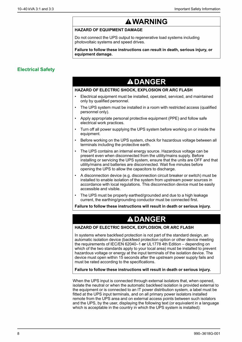
WARNINGHAZARD OF EQUIPMENT DAMAGE
Do not connect the UPS output to regenerative load systems includingphotovoltaic systems and speed drives.
Failure to follow these instructions can result in death, serious injury, orequipment damage.
Electrical Safety
DANGERHAZARD OF ELECTRIC SHOCK, EXPLOSION OR ARC FLASH• Electrical equipment must be installed, operated, serviced, and maintained
only by qualified personnel.• The UPS system must be installed in a room with restricted access (qualified
personnel only).• Apply appropriate personal protective equipment (PPE) and follow safe
electrical work practices.• Turn off all power supplying the UPS system before working on or inside the
equipment.• Before working on the UPS system, check for hazardous voltage between all
terminals including the protective earth.• The UPS contains an internal energy source. Hazardous voltage can be
present even when disconnected from the utility/mains supply. Beforeinstalling or servicing the UPS system, ensure that the units are OFF and thatutility/mains and batteries are disconnected. Wait five minutes beforeopening the UPS to allow the capacitors to discharge.
• A disconnection device (e.g. disconnection circuit breaker or switch) must beinstalled to enable isolation of the system from upstream power sources inaccordance with local regulations. This disconnection device must be easilyaccessible and visible.
• The UPS must be properly earthed/grounded and due to a high leakagecurrent, the earthing/grounding conductor must be connected first.
Failure to follow these instructions will result in death or serious injury.
DANGERHAZARD OF ELECTRIC SHOCK, EXPLOSION, OR ARC FLASH
In systems where backfeed protection is not part of the standard design, anautomatic isolation device (backfeed protection option or other device meetingthe requirements of IEC/EN 62040–1 or UL1778 4th Edition – depending onwhich of the two standards apply to your local area) must be installed to preventhazardous voltage or energy at the input terminals of the isolation device. Thedevice must open within 15 seconds after the upstream power supply fails andmust be rated according to the specifications.
Failure to follow these instructions will result in death or serious injury.
When the UPS input is connected through external isolators that, when opened,isolate the neutral or when the automatic backfeed isolation is provided external tothe equipment or is connected to an IT power distribution system, a label must befitted at the UPS input terminals, and on all primary power isolators installedremote from the UPS area and on external access points between such isolatorsand the UPS, by the user, displaying the following text (or equivalent in a languagewhich is acceptable in the country in which the UPS system is installed):
8 990–3618G-001

Important Safety Information 10–40 kVA 3:1 and 3:3
DANGERHAZARD OF ELECTRIC SHOCK, EXPLOSION, OR ARC FLASH
Risk of Voltage Backfeed. Before working on this circuit: Isolate the UPS andcheck for hazardous voltage between all terminals including the protective earth.
Failure to follow these instructions will result in death or serious injury.
Battery Safety
DANGERHAZARD OF ELECTRIC SHOCK, EXPLOSION, OR ARC FLASH• Battery circuit breakers must be installed according to the specifications and
requirements as defined by Schneider Electric.• Servicing of batteries must only be performed or supervised by qualified
personnel knowledgeable of batteries and the required precautions. Keepunqualified personnel away from batteries.
• Disconnect charging source prior to connecting or disconnecting batteryterminals.
• Do not dispose of batteries in a fire as they can explode.• Do not open, alter, or mutilate batteries. Released electrolyte is harmful to the
skin and eyes. It may be toxic.Failure to follow these instructions will result in death or serious injury.
DANGERHAZARD OF ELECTRIC SHOCK, EXPLOSION, OR ARC FLASH
Batteries can present a risk of electric shock and high short-circuit current. Thefollowing precautions must be observed when working on batteries• Remove watches, rings, or other metal objects.• Use tools with insulated handles.• Wear protective glasses, gloves and boots.• Do not lay tools or metal parts on top of batteries.• Disconnect the charging source prior to connecting or disconnecting battery
terminals.• Determine if the battery is inadvertently grounded. If inadvertently grounded,
remove source from ground. Contact with any part of a grounded battery canresult in electric shock. The likelihood of such shock can be reduced if suchgrounds are removed during installation and maintenance (applicable toequipment and remote battery supplies not having a grounded supply circuit).
Failure to follow these instructions will result in death or serious injury.
DANGERHAZARD OF ELECTRIC SHOCK, EXPLOSION, OR ARC FLASH
When replacing batteries, always replace with the same type and number ofbatteries or battery packs.
Failure to follow these instructions will result in death or serious injury.
990–3618G-001 9

10–40 kVA 3:1 and 3:3 Important Safety Information
CAUTIONRISK OF EQUIPMENT DAMAGE• Wait until the system is ready to be powered up before installing batteries in
the system. The time duration from battery installation until the UPS systemis powered up must not exceed 72 hours or 3 days.
• Batteries must not be stored more than six months due to the requirement ofrecharging. If the UPS system remains de-energized for a long period, werecommend that you energize the UPS system for a period of 24 hours atleast once every month. This charges the batteries, thus avoiding irreversibledamage.
Failure to follow these instructions can result in injury or equipmentdamage.
10 990–3618G-001

Specifications 10–40 kVA 3:1 and 3:3
Specifications
AC Input Specifications
3:3 and 3:1 UPS
10 kVA 15 kVA 20 kVA
Voltage 380 400 415 380 400 415 380 400 415
Connection type 3PH + N + PE
Input frequency (Hz) 45–65
THDI < 9% at full load
Nom. input current (A)1 13 12.5 12 20 19 18 26 25 24
Max. input current (A)2 15.5 15 14.5 22.5 21.5 20.5 29 28 27
Input current limitation (A)3 17.5 17 16 25 24 22.5 32 31 30
Input power factor correction > 0.97 at load > 50%
30 kVA 40 kVA4
Voltage 380 400 415 380 400 415
Connection type 3PH + N + PE
Input frequency (Hz) 45–65
THDI < 9% at full load
Nom. input current (A)1 39.5 38 36 53 50 48
Max. input current (A)2 42 40.5 38.5 56 53 51
Input current limitation (A)3 47 45 42.5 61 59 56
Input power factor correction > 0.97 at load > 50%
Galaxy 300 AC Bypass Input Specifications
3:3 UPS
10 kVA 15 kVA 20 kVA
Voltage 380 400 415 380 400 415 380 400 415
Connection type 3PH + N + PE
Input frequency (Hz) 50/60 ±8%
Nom. bypass current (A) 15 14.5 14 23 22 21 30 29 27
30 kVA 40 kVA
Voltage 380 400 415 380 400 415
Connection type 3PH + N + PE
990–3618G-001 11
1. Input current based on rated load and batteries fully charged.2. Input current based on full battery recharge, nominal voltage, and rated load.3. Current limitation through electronic current limiting is based on full battery recharge and -15% input voltage.4. Only available in 3:3 versions.

10–40 kVA 3:1 and 3:3 Specifications
30 kVA 40 kVA
Voltage 380 400 415 380 400 415
Input frequency (Hz) 50/60 ±8%
Nom. bypass current (A) 45 43 41.5 60 58 55
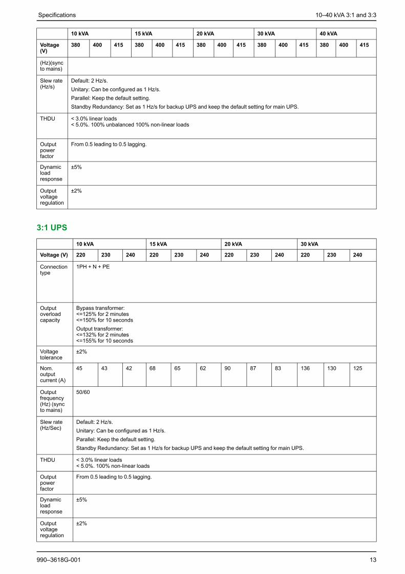
3:1 UPS
10 kVA 15 kVA
Voltage 220 230 240 220 230 240
Connection type 1PH + N + PE
Input frequency (Hz) 50/60 ±8%
Nom. bypass current (A) 45 43.5 41.5 68 65 62
20 kVA 30 kVA
Voltage 220 230 240 220 230 240
Connection type 1PH + N + PE
Input frequency (Hz) 50/60 ±8%
Nom. bypass current (A) 90 87 83 136 130 125
Galaxy 300 AC Output Specifications3:3 UPS: 380, 400, 415 V (400 V 50 Hz is standard but 60 Hz is also possible).Operation at 415 V/60 Hz is not possible and does not correspond to any knownneeds. For all other voltages or voltage combinations, voltage-matchingtransformers are required.
3:1 UPS: 220, 230, 240 V (230 V is standard).
The operating voltage is set via the personalization procedures. The setting mayresult in an overload if the output voltage is +3% and the current is at its rated level.
NOTE: In battery operation overload is not supported.
3:3 UPS
10 kVA 15 kVA 20 kVA 30 kVA 40 kVA
Voltage(V)
380 400 415 380 400 415 380 400 415 380 400 415 380 400 415
Connec-tion type
3PH + N + PE
Outputoverloadcapacity
Bypass transformer:<=125% for 2 minutes<=150% for 10 secondsOutput transformer:<=132% for 2 minutes<=155% for 10 seconds
Voltagetolerance
±2%
Nom.outputcurrent(A)
15 14.5 14 23 22 21 30 29 27 45 43 41.5 60 58 55
Outputfrequency
50/60
12 990–3618G-001
Specifications 10–40 kVA 3:1 and 3:3
10 kVA 15 kVA 20 kVA 30 kVA 40 kVA
Voltage(V)
380 400 415 380 400 415 380 400 415 380 400 415 380 400 415
(Hz)(syncto mains)
Slew rate(Hz/s)
Default: 2 Hz/s.Unitary: Can be configured as 1 Hz/s.Parallel: Keep the default setting.Standby Redundancy: Set as 1 Hz/s for backup UPS and keep the default setting for main UPS.
THDU < 3.0% linear loads< 5.0%. 100% unbalanced 100% non-linear loads
Outputpowerfactor
From 0.5 leading to 0.5 lagging.
Dynamicloadresponse
±5%
Outputvoltageregulation
±2%
3:1 UPS
10 kVA 15 kVA 20 kVA 30 kVA
Voltage (V) 220 230 240 220 230 240 220 230 240 220 230 240
Connectiontype
1PH + N + PE
Outputoverloadcapacity
Bypass transformer:<=125% for 2 minutes<=150% for 10 secondsOutput transformer:<=132% for 2 minutes<=155% for 10 seconds
Voltagetolerance
±2%
Nom.outputcurrent (A)
45 43 42 68 65 62 90 87 83 136 130 125
Outputfrequency(Hz) (syncto mains)
50/60
Slew rate(Hz/Sec)
Default: 2 Hz/s.Unitary: Can be configured as 1 Hz/s.Parallel: Keep the default setting.Standby Redundancy: Set as 1 Hz/s for backup UPS and keep the default setting for main UPS.
THDU < 3.0% linear loads< 5.0%. 100% non-linear loads
Outputpowerfactor
From 0.5 leading to 0.5 lagging.
Dynamicloadresponse
±5%
Outputvoltageregulation
±2%
990–3618G-001 13

10–40 kVA 3:1 and 3:3 Specifications
Battery Specifications
10 kVA 15 kVA 20 kVA 30 kVA 40 kVA
Type VRLA (Valve-Regulated Lead Acid) Battery
Nom. voltage (16blocks/15 blocks)(VDC)
± 192 / ±180
Float voltage (16blocks/15 blocks)(VDC)
± 218 / ±204
End of dischargevoltage (VDC) at100% load
± 158 / ±148
Max. chargingpower for UPS withstandard charger(may drop to lowervalues at low ACinput)5
10-40 kVA: 1744 W
Max. chargingpower for UPS withCLA charger (maydrop to lower valuesat low AC input)6
3052 W 3052 W 3052 W 6104 W 6104 W
Typical rechargetime
Internal charger: (for integrated battery configuration)10 hours - to 90% ±5% capacity after full discharge at min. Config.CLA: (for external battery configuration)24 hours - to 90% ±5% capacity after full discharge at min. Config.
Nom. voltage (V) 12 V/block
End voltage (V) 9.9 V/block (varies from 11.4 V to 9.9 V corresponding to load percentage from low to high)
INom discharge7(A)(15 blocks)
25 37 50 74 99
IMax discharge8(A)(15 blocks)
30 45 60 90 120
Galaxy 300 Heat Dissipation
3:3 UPS
Heat dissipation9 10 kVA 15 kVA 20 kVA
Load (%) 100 75 50 100 75 50 100 75 50
Heat dissipation (Watt) 656 514 420 937 712 514 1260 937 656
Heat dissipation9 30 kVA 40 kVA
Load (%) 100 75 50 100 75 50
Heat dissipation (Watt) 1804 1313 945 2479 1804 1195
14 990–3618G-001
5. UPS with standard charger is to be used with internal batteries ONLY.6. UPS with CLA charger is to be used with external batteries ONLY.7. Nominal battery discharge current based on rated load and nominal battery voltage.8. Maximum battery discharge current based on rated load at the end of the discharge.9. Batteries fully charged.

Specifications 10–40 kVA 3:1 and 3:3
3:1 UPS
Heat dissipation10 10 kVA 15 kVA
Load (%) 100 75 50 100 75 50
Heat dissipation (Watt) 707 577 463 1045 786 577
Heat dissipation10 20 kVA 30 kVA
Load (%) 100 75 50 100 75 50
Heat dissipation (Watt) 1212 888 612 1876 1417 1029
Recommended Cable SizesAll wiring must comply with all applicable national and/or electrical codes. Thebelow specifications are recommendations only.
AC cable sizes are determined for:- the TNS system for copper, single-core cables, type U1000 R02V, 100 m longwith a line voltage drop <3%, installed on perforated cable trays, XLPE-typeinsulation, single-layer trefoil formation, THDI between 15% and 33%, 35° C at 400V, grouped in four touching cables.
Battery cable sizes are determined for:- copper, single-core cables, type U1000 R02V, maximum length 25 m with a linevoltage drop <1%.
3:3 UPS
3:3 UPS – Single mains 10 kVA 15 kVA 20 kVA 30 kVA 40 kVA
min max min max min max min max min max
Mains input (mm2) 10 35 10 35 10 35 16 35 25 35
AC output (mm2) 10 35 10 35 10 35 16 35 25 35
Battery input (mm2) 70° C 10 35 10 35 16 35 25 35 35 35
3:3 UPS – Dual mains 10 kVA 15 kVA 20 kVA 30 kVA 40 kVA
min max min max min max min max min max
Mains input (mm2) 10 35 10 35 10 35 16 35 25 35
AC output (mm2) 10 35 10 35 10 35 16 35 25 35
Battery input (mm2) 70° C 10 35 10 35 16 35 25 35 35 35
Bypass (mm2) 10 35 10 35 10 35 16 35 25 35
3:1 UPS
3:1 UPS – Single mains 10 kVA 15 kVA 20 kVA 30 kVA
min max min max min max min max
Mains input (mm2) 16 35 25 35 35 90 70 90
AC output (mm2) 16 35 25 35 35 90 70 90
Battery input (mm2) 70° C 10 35 10 35 16 35 25 35
990–3618G-001 15
10. Batteries fully charged.
10–40 kVA 3:1 and 3:3 Specifications
3:1 UPS – Dual mains 10 kVA 15 kVA 20 kVA 30 kVA
min max min max min max min max
Mains input (mm2) 10 35 10 35 35 90 35 90
AC output (mm2) 16 35 25 35 35 90 70 90
Battery input (mm2) 70° C 10 35 10 35 16 35 25 35
Bypass (mm2) 16 35 25 35 35 90 70 90
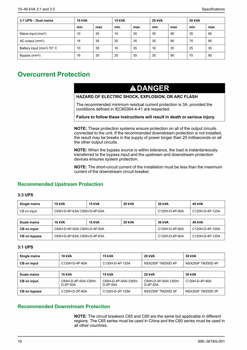
Overcurrent Protection
DANGERHAZARD OF ELECTRIC SHOCK, EXPLOSION, OR ARC FLASH
The recommended minimum residual current protection is 3A, provided theconditions defined in IEC60364-4-41 are respected.
Failure to follow these instructions will result in death or serious injury.
NOTE: These protection systems ensure protection on all of the output circuitsconnected to the unit. If the recommended downstream protection is not installed,the result may be breaks in the supply of power longer than 20 milliseconds on allthe other output circuits.
NOTE:When the bypass source is within tolerance, the load is instantaneouslytransferred to the bypass input and the upstream and downstream protectiondevices ensures system protection.
NOTE: The short-circuit current of the installation must be less than the maximumcurrent of the downstream circuit breaker.
Recommended Upstream Protection
3:3 UPS
Single mains 10 kVA 15 kVA 20 kVA 30 kVA 40 kVA
CB on input C65H-D-4P-63A/ C60H-D-4P-63A C120H-D-4P-80A C120H-D-4P-125A
Duals mains 10 kVA 15 kVA 20 kVA 30 kVA 40 kVA
CB on input C65H-D-4P-50A/ C60H-D-4P-50A C120H-D-4P-80A C120H-D-4P-100A
CB on bypass C65H-D-4P-63A/ C60H-D-4P-63A C120H-D-4P-80A C120H-D-4P-125A
3:1 UPS
Single mains 10 kVA 15 kVA 20 kVA 30 kVA
CB on input C120H-D-4P-80A C120H-D-4P-125A NSX250F TM200D 4P NSX250F TM250D 4P
Duals mains 10 kVA 15 kVA 20 kVA 30 kVA
CB on input C65H-D-4P-50A/ C60H-D-4P-50A
C65H-D-4P-50A/ C60H-D-4P-50A
C65H-D-4P-50A/ C60H-D-4P-50A
C120H-D-4P-80A
CB on bypass C120H-D-2P-80A C120H-D-2P-125A NSX250F TM200D 3P NSX250F TM250D 3P
Recommended Downstream Protection
NOTE: The circuit breakers C65 and C60 are the same but applicable in differentregions. The C65 series must be used in China and the C60 series must be used inall other countries.
16 990–3618G-001

Specifications 10–40 kVA 3:1 and 3:3
3:3 UPS
10 kVA 15 kVA 20 kVA 30 kVA 40 kVA
Downstream CB C65N-B–4P-10A/C60N-B-4P-10AC65N-B-4P-10A/C60N-C-4P-6A
C65N-B-4P-16A/C60N-B-4P-16AC65N-C-4P-10A/C60N-C-4P-10A
C65N-B-4P-20A/C60N-B-4P-20AC65N-C-4P-10A/C60N-C-4P-10A
3:1 UPS
10 kVA 15 kVA 20 kVA 30 kVA
Downstream CB C65N-B-2P-25A/C60N-B-2P-25AC65N-C-2P-10A/C60N-C-2P-10A
C65N-B-2P-32A/C60N-B-2P-32AC65N-C-2P-16A/C60N-C-2P-16A
C65N-B-2P-50A/C60N-B-2P-50AC65N-C-2P-25A/C60N-C-2P-25A
Torque Specifications
Bolt size Torque
M3 1 Nm
M4 1.2 Nm – 2 Nm
M5 3.5 Nm – 4.5 Nm
M6 4.5 Nm – 6 Nm
For batteries: Use the torque recommended by Schneider Electric or by the third party batteryvendor.
990–3618G-001 17

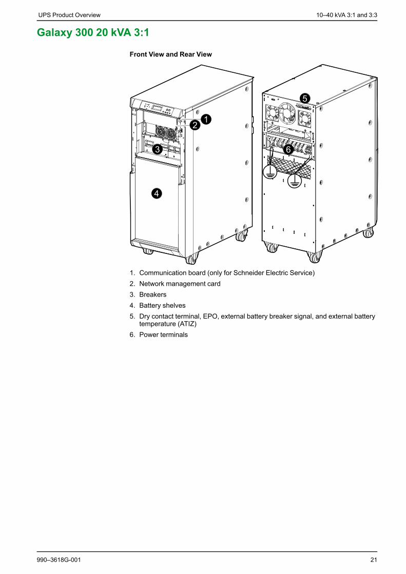
10–40 kVA 3:1 and 3:3 UPS Product Overview
UPS Product OverviewThe communication board, network management card, breakers, and batteryshelves are located behind the front door and accessed by pushing the white doton the right side of the door. The connectors and power terminals are accessedfrom the rear.
Galaxy 300 30 kVA/ 40 kVA 3:3
Front View and Rear View
1. Communication board (only for Schneider Electric Service)2. Network management card3. Breakers4. Battery shelves
18 990–3618G-001

UPS Product Overview 10–40 kVA 3:1 and 3:3
5. Dry contact terminal, EPO, external battery breaker signal, and external batterytemperature (ATIZ)
6. Power terminals
Galaxy 300 30 kVA 3:1
Front View and Rear View
1. Communication board (only for Schneider Electric Service)2. Network management card3. Breakers4. Battery shelves5. Dry contact terminal, EPO, external battery breaker signal, and external battery
temperature (ATIZ)6. Power terminals
990–3618G-001 19

10–40 kVA 3:1 and 3:3 UPS Product Overview
Galaxy 300 10 kVA/ 15 kVA/ 20 kVA 3:3
Front View and Rear View
1. Communication board (only for Schneider Electric Service)2. Network management card3. Breakers4. Battery shelves5. Dry contact terminal, EPO, external battery breaker signal, and external battery
temperature (ATIZ)6. Power terminals
20 990–3618G-001
UPS Product Overview 10–40 kVA 3:1 and 3:3
Galaxy 300 20 kVA 3:1
Front View and Rear View
1. Communication board (only for Schneider Electric Service)2. Network management card3. Breakers4. Battery shelves5. Dry contact terminal, EPO, external battery breaker signal, and external battery
temperature (ATIZ)6. Power terminals
990–3618G-001 21

10–40 kVA 3:1 and 3:3 UPS Product Overview
Galaxy 300 10 kVA/ 15 kVA 3:1
Front View and Rear View
1. Communication board (only for Schneider Electric Service)2. Network management card3. Breakers4. Battery shelves5. Dry contact terminal, EPO, external battery breaker signal, and external battery
temperature (ATIZ)6. Power terminals
Parallel SystemThe UPS can be installed in parallel with a maximum of two UPS units. Install bothUPS units separately as instructed in this manual. The parallel connection betweenthe two UPS units can only be carried out by a Schneider Electric Field ServiceEngineer using the parallel kit bought separately.
22 990–3618G-001

UPS Product Overview 10–40 kVA 3:1 and 3:3
UPS Cabinet ClearanceNOTE: Clearance dimensions are published for airflow and service access only.Consult with the local safety codes and standards for additional requirements inyour local area.
NOTE: 500 mm rear service clearance is recommended.
990–3618G-001 23

10–40 kVA 3:1 and 3:3 Prepare for Installation
Prepare for Installation
Floor Anchoring (Optional)
CAUTIONHAZARD OF TILTING
A UPS configuration without internal batteries must be anchored to the floorbecause it is top-heavy.
Failure to follow these instructions can result in injury or equipmentdamage.
NOTE: For parallel systems the distance between the UPS cabinets is limited. Theparallel kit includes two cables (5 and 15 meters). The maximum distance betweentwo UPS cabinets is 2 m for the 5 m cable and 12 m for the 15 m cable.
NOTE: The UPS system and battery cabinet must be installed on a non-inflammable, level, and solid floor.
NOTE: The UPS can be anchored to the floor in two ways depending on theavailable floor space.
Method 1: Unlimited Space Available
1. Mount the four brackets on the UPS as shown.
Front View
Method 2: Limited Space Available
1. Drill four holes according to the UPS footprint (see illustration) and install fourM8 bolts into the floor for anchoring.
24 990–3618G-001

Prepare for Installation 10–40 kVA 3:1 and 3:3
2. Tighten the bolts.
3. Push the UPS in between the four floor bolts.
4. Mount the four brackets on the UPS.
Front View
5. Make sure that the slots on each bracket grasp the floor bolts.
6. Lock the two front wheels by tightening the screws.
Front View
990–3618G-001 25
10–40 kVA 3:1 and 3:3 Prepare for Installation
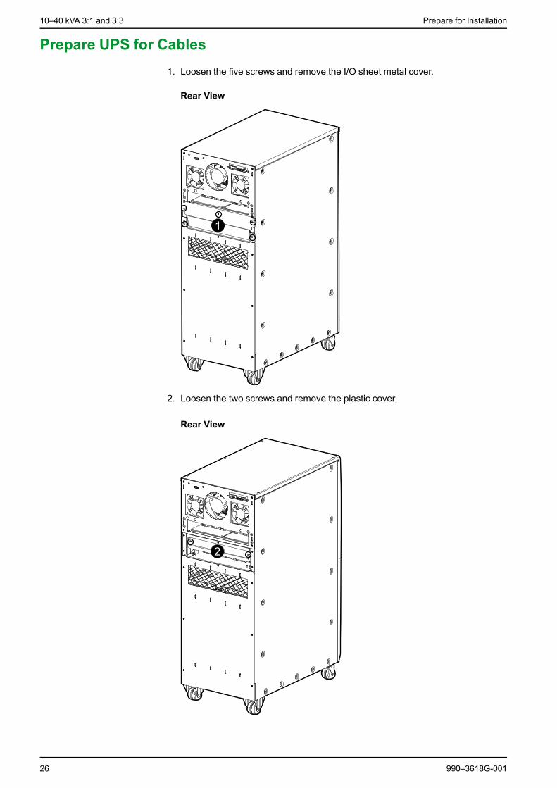
Prepare UPS for Cables1. Loosen the five screws and remove the I/O sheet metal cover.
Rear View
2. Loosen the two screws and remove the plastic cover.
Rear View
26 990–3618G-001

Connect the Power Cables 10–40 kVA 3:1 and 3:3
Connect the Power CablesNOTE: For installation of backfeed protection, see Install Backfeed Protection,page 33.
Connect the UPS Power Cables
DANGERHAZARD OF ELECTRIC SHOCK, EXPLOSION, OR ARC FLASH
In frequency converter operation mode the maintenance bypass breaker (Q3BP)and the static bypass breaker (QM2) must be in the OFF (opened) position.
Failure to follow these instructions will result in death or serious injury.
NOTICERISK OF ERRATIC SYSTEM OPERATION
If the neutral line connection is not reliable, the system will work abnormally.
Failure to follow these instructions can result in equipment damage.
NOTE: A padlock is available from Schneider Electric and is advisable for thefrequency converter mode (padlock catalog number: 26970).
990–3618G-001 27

10–40 kVA 3:1 and 3:3 Connect the Power Cables
Rear View of the UPS
1. Connect the PE-cables for input, for bypass, and for the load.
2. Connect the input cables (N, L1, L2, L3) to the input terminals starting with N.
NOTE: For single mains systems, move to step 5.3. Dual mains systems only: Remove the cable(s) between the bypass and the
input terminals.
28 990–3618G-001

Connect the Power Cables 10–40 kVA 3:1 and 3:3
4. Dual mains systems only: If you want the option of turning the UPS intofrequency converter operation (as described in the operation manual),you must ignore this step and move to step 5. Otherwise, you must connectthe bypass cables to the bypass terminals. 3:3 (N, L1, L2, L3), 3:1 (N, L1).
5. Connect the cables from the critical load to the output terminals. 3:3 (N, L1, L2,L3), 3:1 (N and L1).
6. External battery solution only: Connect the battery cables (BAT+, N, BAT-) tothe battery terminals. The battery cables will be connected to the externalbattery solution later.
7. Reinstall the plastic cover and the I/O sheet metal cover removed in PrepareUPS for Cables, page 26.
DANGERHAZARD OF ELECTRIC SHOCK, EXPLOSION, OR ARC FLASH
The I/O sheet metal cover must be fixed in the lowest position for safetyreasons.
Failure to follow these instructions will result in death or serious injury.
8. Bundle the input cables, the bypass cables, the battery cables (if present) andthe output cables as four separate groups of cables.
9. Attach all cables to the fixtures (shown below) with cable ties.
990–3618G-001 29

10–40 kVA 3:1 and 3:3 Connect the Power Cables
10.If the frequency converter option was made available by ignoring step 4, apadlock from Schneider Electric must now be installed on the static bypassbreaker (QM2) and the maintenance bypass breaker (Q3BP) in the OFF(opened) position.
Front View of 3:3 30–40 kVA, and 3:1 20–30 kVA
Front View of 3:3 10–20 kVA, and 3:1 10–15 kVA
Connect the UPS Power Cables for Standby Redundancy System
NOTICERISK OF ERRATIC SYSTEM OPERATION
If the neutral line connection is not reliable, the system will work abnormally.
Failure to follow these instructions can result in equipment damage.
NOTE: Only two UPS units can be installed in a standby redundancy system. Bothunits must have the same power rating and topology (both 3:3 or both 3:1).
30 990–3618G-001

Connect the Power Cables 10–40 kVA 3:1 and 3:3
Rear View of the UPS
1. Connect the PE cables for input, for bypass, and for the load.
2. Connect the input cables (N, L1, L2, L3) to the input terminals starting with N onUPS 1.
3. For Dual mains systems only: Remove the cable(s) between the input andthe bypass terminals on UPS 1.
4. For Dual mains systems only:Connect the bypass cables to the bypassterminals (3:3 (N, L1, L2, L3), 3:1 (N, L1)) on UPS 1.
5. Connect input cables on UPS 2.
990–3618G-001 31

10–40 kVA 3:1 and 3:3 Connect the Power Cables
6. Remove the cable(s) between input and bypass terminals on UPS 2.
7. Connect output (3:3 (N, L1, L2, L3), 3:1 (N and L1)) from UPS 1 to the bypasson UPS 2.
8. Connect the cables from the critical load to the output terminals (3:3 (N, L1, L2,L3), 3:1 (N and L1)) on UPS 2.
9. External battery solution only: Connect the battery cables (BAT+, N, BAT-) tothe battery terminals. The battery cables will be connected to the externalbattery solution later.
10.Reinstall the plastic cover and the I/O sheet metal cover removed whilepreparing the UPS for cables.
DANGERHAZARD OF ELECTRIC SHOCK, EXPLOSION, OR ARC FLASH
The I/O sheet metal cover must be fixed in the lowest position for safetyreasons.
Failure to follow these instructions will result in death or serious injury.
11.Bundle the input cables, the bypass cables, the battery cables (if present), andthe output cables as four separate groups of cables.
12.Attach all cables to the fixtures (shown below) with cable ties.
32 990–3618G-001
Install Backfeed Protection 10–40 kVA 3:1 and 3:3
Install Backfeed ProtectionNOTE: The presence of a backfeed on each input mains (Input and Bypass input),is mandatory according to IEC 62040-1.
An additional external isolation device must be installed in the UPS system. Amagnetic contactor or a circuit breaker with UVR (Under Voltage Release)functionality can be used for this purpose. In the shown examples, the isolationdevice is a magnetic contactor (marked with a C1 for single feed configurationsand marked with a C1 and C2 for dual feed configurations).
The isolation device must be able to carry the UPS input current, check with therelevant input current of the UPS specifications.
NOTE: The 24 V source should be generated from the input source in single mainsconfigurations and from the bypass source in dual mains configurations.
NOTE: The examples shown in the backfeed protection instructions are for TNearthing systems. For other earthing systems, the external isolation deviceschematics are similar; refer to Galaxy 300 Earthing Manual. In case of an ITearthing system installation, where the upstream protection is a 4 pole device, theexternal isolation device must also be 4 pole.
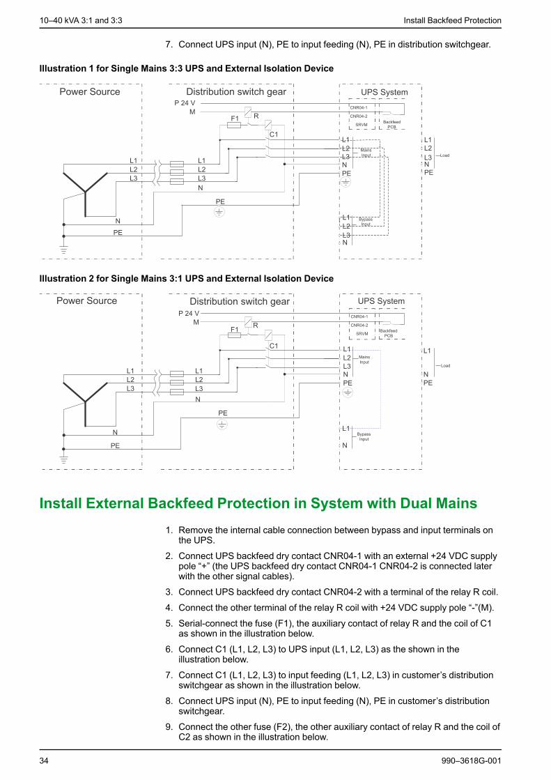
If the UPS is fed by single mains, connect the backfeed protection as instructed inInstall External Backfeed Protection in System with Single Mains, page 33.
If the UPS is fed by dual mains only, connect the backfeed protection as instructedin Install External Backfeed Protection in System with Dual Mains, page 34.
Install External Backfeed Protection in System with Single Mains1. Connect UPS backfeed dry contact CNR04-1 with an external +24 VDC supply
pole “+” (the UPS backfeed dry contact CNR04-1 CNR04-2 is connected laterwith the other signal cables).
2. Connect UPS backfeed dry contact CNR04-2 with a terminal of the relay R coil.
3. Connect the other terminal of the relay R coil with +24 VDC supply pole “-”(M).
4. Serial-connect the fuse (F1), the auxiliary contact of relay R and the coil of C1as shown in the illustration below.
5. Connect C1 (L1, L2, L3) to UPS input (L1, L2, L3) as shown in the illustrationbelow.
6. Connect C1 (L1, L2, L3) to input feeding (L1, L2, L3) in distribution switchgearas shown in the illustration below.
990–3618G-001 33
10–40 kVA 3:1 and 3:3 Install Backfeed Protection
7. Connect UPS input (N), PE to input feeding (N), PE in distribution switchgear.
Illustration 1 for Single Mains 3:3 UPS and External Isolation Device
Illustration 2 for Single Mains 3:1 UPS and External Isolation Device
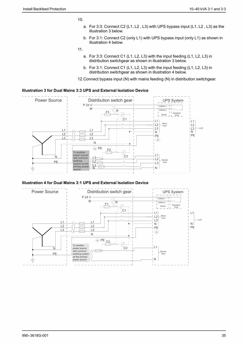
Install External Backfeed Protection in System with Dual Mains1. Remove the internal cable connection between bypass and input terminals on
the UPS.
2. Connect UPS backfeed dry contact CNR04-1 with an external +24 VDC supplypole “+” (the UPS backfeed dry contact CNR04-1 CNR04-2 is connected laterwith the other signal cables).
3. Connect UPS backfeed dry contact CNR04-2 with a terminal of the relay R coil.
4. Connect the other terminal of the relay R coil with +24 VDC supply pole “-”(M).
5. Serial-connect the fuse (F1), the auxiliary contact of relay R and the coil of C1as shown in the illustration below.
6. Connect C1 (L1, L2, L3) to UPS input (L1, L2, L3) as the shown in theillustration below.
7. Connect C1 (L1, L2, L3) to input feeding (L1, L2, L3) in customer’s distributionswitchgear as shown in the illustration below.
8. Connect UPS input (N), PE to input feeding (N), PE in customer’s distributionswitchgear.
9. Connect the other fuse (F2), the other auxiliary contact of relay R and the coil ofC2 as shown in the illustration below.
34 990–3618G-001
Install Backfeed Protection 10–40 kVA 3:1 and 3:3
10.
a. For 3:3: Connect C2 (L1, L2 , L3) with UPS bypass input (L1, L2 , L3) as theillustration 3 below.
b. For 3:1: Connect C2 (only L1) with UPS bypass input (only L1) as shown inillustration 4 below.
11.
a. For 3:3: Connect C1 (L1, L2, L3) with the input feeding (L1, L2, L3) indistribution switchgear as shown in illustration 3 below.
b. For 3:1: Connect C1 (L1, L2, L3) with the input feeding (L1, L2, L3) indistribution switchgear as shown in illustration 4 below.
12.Connect bypass input (N) with mains feeding (N) in distribution switchgear.
Illustration 3 for Dual Mains 3:3 UPS and External Isolation Device
Illustration 4 for Dual Mains 3:1 UPS and External Isolation Device
990–3618G-001 35
10–40 kVA 3:1 and 3:3 Install Battery Solution
Install Battery Solution
DANGERHAZARD OF ELECTRIC SHOCK, EXPLOSION, OR ARC FLASH
The Galaxy 300 UPS can be used with EITHER internal or external batteries. AUPS unit containing internal batteries CANNOT be used with external batteries.Remove internal batteries before connecting external batteries to the UPS.
Failure to follow these instructions will result in death or serious injury.
DANGERHAZARD OF ELECTRIC SHOCK, EXPLOSION, OR ARC FLASH• Make sure that the battery breaker is open before starting.• Check the DC voltages with a DC voltage multimeter versus the battery
voltage before continuing.Failure to follow these instructions will result in death or serious injury.
Depending on your chosen solution, follow the appropriate steps in this chapter.Solutions described:• Internal batteries for the UPS – See Install the Internal Batteries in the Galaxy
300 UPS, page 40.• Galaxy 300 battery cabinet (1300 mm) – See Install a Galaxy 300 Battery
Cabinet (1300 mm), page 44.• 1900 mm battery cabinet – See Install a Galaxy 1900 mm Battery Cabinet,
page 53.• Third party battery solution – See Connect Battery and Signal Cables to
Third Party Battery Solution, page 60.
36 990–3618G-001

Install Battery Solution 10–40 kVA 3:1 and 3:3
Battery Cabinet Product Overview
Galaxy 300 Battery Cabinet (1300 mm)
A. Battery shelvesB. Battery circuit breakerC. Ground cable connection (from the UPS)D. Battery temperature sensor (ATIZ)E. Connection terminal (for ATIZ, circuit breaker detection and power supply)
Front View
990–3618G-001 37
10–40 kVA 3:1 and 3:3 Install Battery Solution
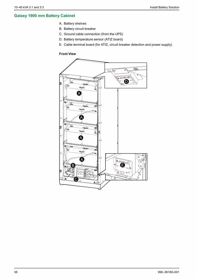
Galaxy 1900 mm Battery Cabinet
A. Battery shelvesB. Battery circuit breakerC. Ground cable connection (from the UPS)D. Battery temperature sensor (ATIZ board)E. Cable terminal board (for ATIZ, circuit breaker detection and power supply)
Front View
38 990–3618G-001

Install Battery Solution 10–40 kVA 3:1 and 3:3
Battery Cabinet Clearance
NOTE: Clearance dimensions are published for airflow and service access only.Consult with the local safety codes and standards for additional requirements inyour local area.
NOTE: 500 mm rear service clearance is recommended.
990–3618G-001 39
10–40 kVA 3:1 and 3:3 Install Battery Solution
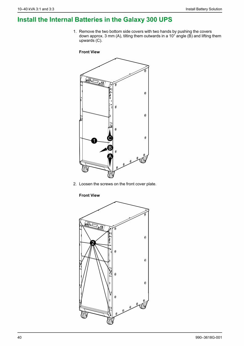
Install the Internal Batteries in the Galaxy 300 UPS1. Remove the two bottom side covers with two hands by pushing the covers
down approx. 3 mm (A), tilting them outwards in a 10° angle (B) and lifting themupwards (C).
Front View
2. Loosen the screws on the front cover plate.
Front View
40 990–3618G-001

Install Battery Solution 10–40 kVA 3:1 and 3:3
3. Tilt out the front cover and disconnect the flat cable between the display and theUPS cabinet.
4. Remove the front cover.
Side View
5. Remove the bolt on each side of all shelves where necessary.
Front View
Cable Connection of Pre-Installed Internal Batteries
1. Remove all strapping and cardboard from the batteries.
2. Interconnect the shelves according to the labels in the cabinet or the diagramsinside the battery cabinet (cables are provided).
990–3618G-001 41

10–40 kVA 3:1 and 3:3 Install Battery Solution
3. Remove the plate and connect the battery cable from the shelves to the batterybreaker according to the labels in the cabinet or the diagrams inside the batterycabinet (cables are provided).
Front View
4. Reattach the bolt on each side of all shelves where necessary.
Front View
5. Lift up the front cover and reconnect the flat cable between the display and theUPS.
6. Reinstall the front cover with the screws.
Cable Connection of Not Pre-Installed Internal Batteries
1. Pull out the required number of shelves needed for the batteries.
2. Place the batteries on the shelves and interconnect the batteries (cables arenot provided). Secure the cables with cable ties.
3. Push the battery shelves into the cabinet.
4. Interconnect the shelves according to the diagrams inside the battery cabinet(cables are not provided).
42 990–3618G-001
Install Battery Solution 10–40 kVA 3:1 and 3:3
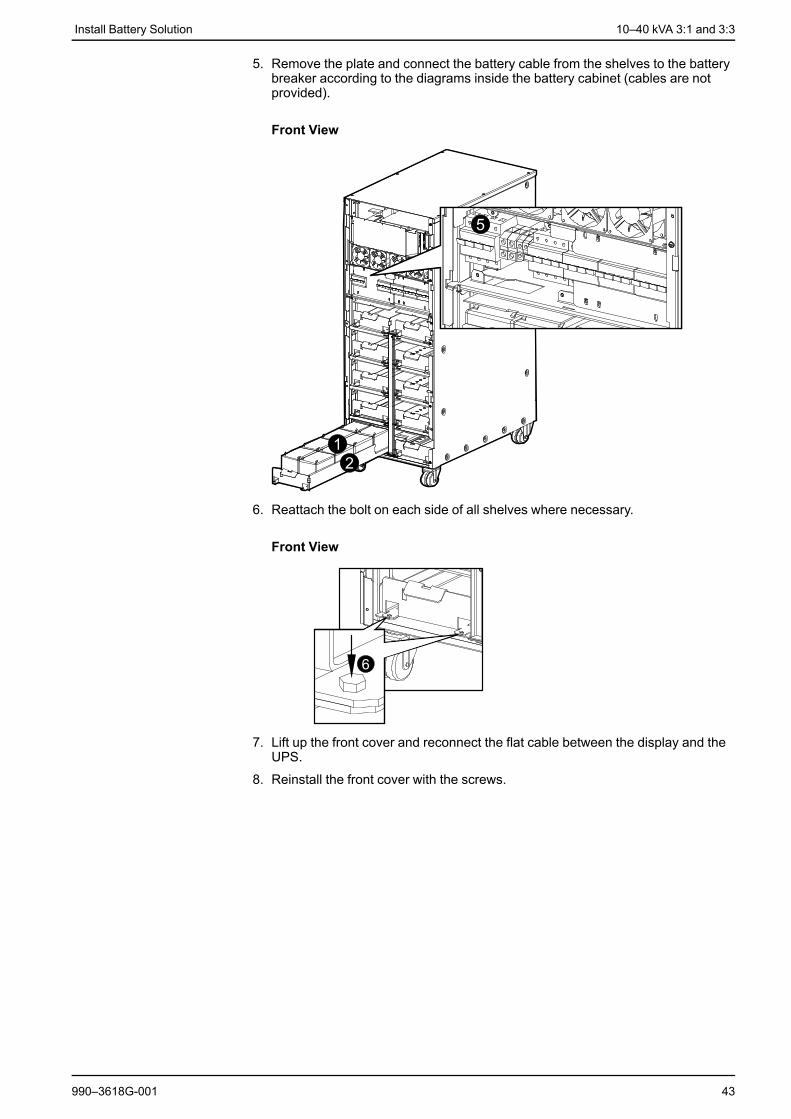
5. Remove the plate and connect the battery cable from the shelves to the batterybreaker according to the diagrams inside the battery cabinet (cables are notprovided).
Front View
6. Reattach the bolt on each side of all shelves where necessary.
Front View
7. Lift up the front cover and reconnect the flat cable between the display and theUPS.
8. Reinstall the front cover with the screws.
990–3618G-001 43

10–40 kVA 3:1 and 3:3 Install Battery Solution
Install a Galaxy 300 Battery Cabinet (1300 mm)
Prepare Galaxy 300 Battery Cabinet (1300 mm) for Cables
1. Lock the two front wheels by tightening the screws.
2. Open the unlocked front door.
NOTE: The key to the door can be found in the accessories package located inthe cabinet.
Front View
3. Remove both side panels.
Front View
44 990–3618G-001

Install Battery Solution 10–40 kVA 3:1 and 3:3
Connect Internal Cables in Galaxy 300 Battery Cabinet (1300mm) with Pre-Installed Batteries
DANGERHAZARD OF ELECTRIC SHOCK, EXPLOSION, OR ARC FLASH
Remove all cardboard pieces, which are used to protect the batteries duringtransport. Make sure that cables and copper busbars are separated.
Failure to follow these instructions will result in death or serious injury.
NOTE: A maximum of two battery cabinets can be connected to the UPS (onebattery cabinet with a circuit breaker plus one cabinet without a circuit breaker) bya batch cable between the UPS and the circuit breaker in the battery cabinet.
1. Remove the left and right plastic cover from the battery breaker by removing thefour screws (two on each plastic cover).
Front View
2. Cut off the belts to remove the carton paper.
3. Run the cables inside each shelf and connect to the batteries.
4. Run the cables between the shelves.
990–3618G-001 45

10–40 kVA 3:1 and 3:3 Install Battery Solution
5. Run the cables between the shelves and the circuit breaker.
NOTE: If the cables have more than one terminal, then the unconnectedterminals must be isolated with insulation tape before connecting the otherterminal.
Front View
Connect Internal Cables in Galaxy 300 Battery Cabinet (1300mm) without Pre-Installed Batteries
DANGERHAZARD OF ELECTRIC SHOCK, EXPLOSION, OR ARC FLASH
Schneider Electric is not responsible for the wiring of external third partybatteries. Follow the instructions from the battery manufacturer.
Failure to follow these instructions will result in death or serious injury.
DANGERHAZARD OF ELECTRIC SHOCK, EXPLOSION, OR ARC FLASH
Remove all cardboard pieces, which are used to protect the batteries duringtransport. Make sure that cables and copper busbars are separated.
Failure to follow these instructions will result in death or serious injury.
NOTE: Before the installation of batteries, you must select and follow the diagramsinside the battery cabinet which apply to your configuration.
NOTE: The maximum load capacity of each battery shelf is 155 kg.
NOTE: A maximum of four battery shelves can be installed.
NOTE: A maximum of two battery cabinets can be connected to the UPS (onebattery cabinet with a circuit breaker plus one cabinet without a circuit breaker) bya batch cable between the UPS and the circuit breaker in the battery cabinet.
1. Insert the batteries on the shelves starting from the bottom according to therelevant diagram inside the battery cabinet.
46 990–3618G-001

Install Battery Solution 10–40 kVA 3:1 and 3:3
2. Install a battery breaker.
3. Cut off the belts to remove the carton paper.
4. Run the cables inside each shelf and connect to the batteries.
5. Run the cables between the shelves.
6. Run the cables between the shelves and the circuit breaker.
NOTE: If the cables have more than one terminal, then the unconnectedterminals must be isolated with insulation tape before connecting the otherterminal.
Front View
Connect Battery Cables from UPS to the Galaxy 300 Battery Cabinet (1300 mm)
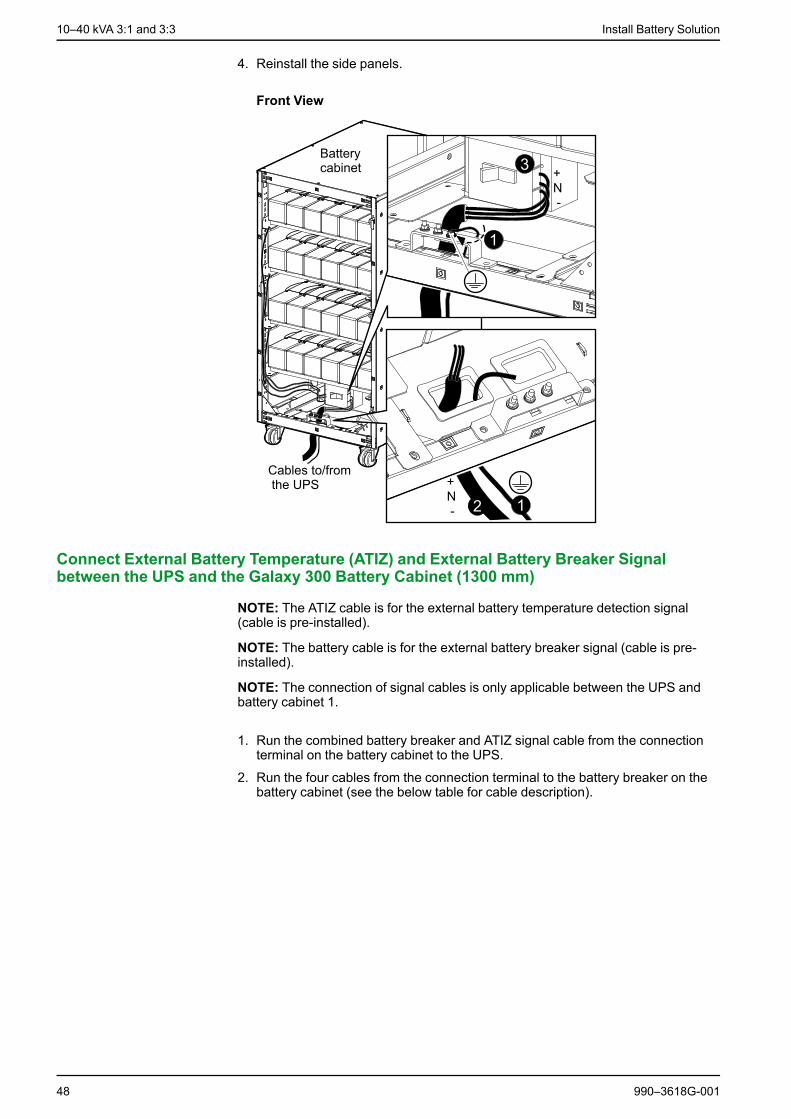
1. Run the Protective Earth (PE) cable from the UPS up through the bottom fronthole of the battery cabinet and connect it to the busbar.
2. Run the battery cables (BAT+, N, and BAT-) from the UPS up through thebottom front hole.
3. Attach the cables to the right side of the battery breaker.
990–3618G-001 47
10–40 kVA 3:1 and 3:3 Install Battery Solution
4. Reinstall the side panels.
Front View
Connect External Battery Temperature (ATIZ) and External Battery Breaker Signalbetween the UPS and the Galaxy 300 Battery Cabinet (1300 mm)
NOTE: The ATIZ cable is for the external battery temperature detection signal(cable is pre-installed).
NOTE: The battery cable is for the external battery breaker signal (cable is pre-installed).
NOTE: The connection of signal cables is only applicable between the UPS andbattery cabinet 1.
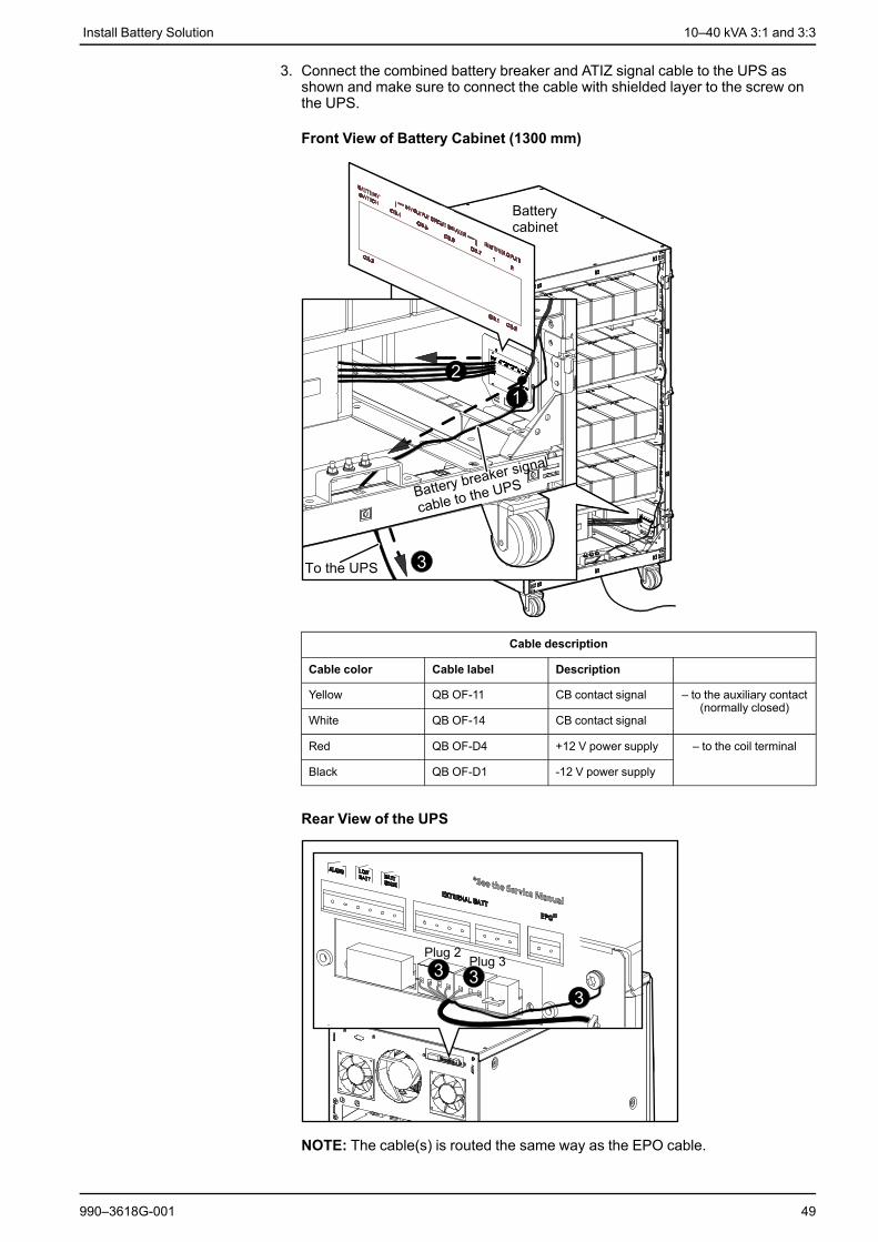
1. Run the combined battery breaker and ATIZ signal cable from the connectionterminal on the battery cabinet to the UPS.
2. Run the four cables from the connection terminal to the battery breaker on thebattery cabinet (see the below table for cable description).
48 990–3618G-001
Install Battery Solution 10–40 kVA 3:1 and 3:3
3. Connect the combined battery breaker and ATIZ signal cable to the UPS asshown and make sure to connect the cable with shielded layer to the screw onthe UPS.
Front View of Battery Cabinet (1300 mm)
Cable description
Cable color Cable label Description
Yellow QB OF-11 CB contact signal – to the auxiliary contact(normally closed)
White QB OF-14 CB contact signal
Red QB OF-D4 +12 V power supply – to the coil terminal
Black QB OF-D1 -12 V power supply
Rear View of the UPS
NOTE: The cable(s) is routed the same way as the EPO cable.
990–3618G-001 49

10–40 kVA 3:1 and 3:3 Install Battery Solution
Connect Battery and Signal Cables from the Galaxy 300 Battery Cabinet (1300 mm) to aRunning UPS
DANGERHAZARD OF ELECTRIC SHOCK, EXPLOSION, OR ARC FLASH
This procedure describes how to connect a battery cabinet to a UPS running innormal operation. Do not connect a battery cabinet to a running UPS withinternal batteries – Remove all internal batteries first.
Failure to follow these instructions will result in death or serious injury.
NOTE: A maximum of two battery cabinets can be connected to the UPS (onebattery cabinet with a circuit breaker plus one cabinet without a circuit breaker) bya batch cable between the UPS and the circuit breaker in the battery cabinet.
NOTE: Before carrying out the below procedure, make sure that the UPS isrunning in normal operation with no internal UPS faults displayed. In normaloperation four breakers (QM1,QFB,QM2,QOP) must be in the ON (closed)position and two breakers (Q3BP,QB) must be in the OFF (opened) position.
1. Turn the UPS into maintenance bypass operation:
a. Press the Inverter OFF button for three seconds and then turn the inputbreaker (QM1) to the OFF (opened) position.
b. Turn the maintenance bypass breaker (Q3BP) to the ON (closed) position.c. Turn the static bypass breaker (QM2) to the OFF (opened) position.d. Turn the output breaker (QOP) to the OFF (opened) position.
2. Isolate the batteries by turning the UPS battery cabinet breaker (QFB) to theOFF (opened) position.
DANGERHAZARD OF ELECTRIC SHOCK, EXPLOSION, OR ARC FLASH
Check the DC voltages with a DC voltage multimeter versus the batteryvoltage before continuing.
Failure to follow these instructions will result in death or serious injury.
3. Run a Protective Earth (PE) cable from the UPS up through the bottom fronthole of the battery cabinet and connect it to the busbar.
4. Run the battery cables (BAT+, N, and BAT-) from the UPS up through thebottom front hole.
5. Attach the cables to the right side of the battery breaker.
50 990–3618G-001

Install Battery Solution 10–40 kVA 3:1 and 3:3
6. Reinstall the side panels.
Front View of Battery Cabinet (1300 mm)
7. Reinstall the plastic cover and the I/O sheet metal cover removed on the UPS –these covers were removed while preparing the UPS for cables.
DANGERHAZARD OF ELECTRIC SHOCK, EXPLOSION, OR ARC FLASH
The I/O sheet metal cover must be fixed in the lowest position for safetyreasons.
Failure to follow these instructions will result in death or serious injury.
990–3618G-001 51

10–40 kVA 3:1 and 3:3 Install Battery Solution
8. Connect the combined battery breaker and ATIZ signal cable to the UPS asshown and make sure to connect the cable with shielded layer to the screw onthe UPS.
NOTE: See Connect External Battery Temperature (ATIZ) and External BatteryBreaker Signal between the UPS and the Galaxy 300 Battery Cabinet (1300mm), page 48 for information on how to route the cable(s)
Rear View of the UPS
9. Turn the UPS back into normal operation:
a. Turn the output breaker (QOP) to the ON (closed) position.b. Turn the static bypass breaker (QM2) to the ON (closed) position.c. Wait a minute for the static bypass breaker LED and the output breaker LED
to turn green.
d. Turn the maintenance bypass breaker (Q3BP) to the OFF (opened)position.
e. Turn the battery cabinet breaker (QFB) to the ON (closed) position.f. Turn the input breaker (QM1) to the ON (closed) position.g. When the soft start has finished, press the INVERTER ON button.
10.Check the LEDs to see if the UPS is running in normal operation:• PFC LED: green• INVERTER LED: green• LOAD LED: green• LOAD PROTECTED LED: green• Other LEDs: OFF
52 990–3618G-001
Install Battery Solution 10–40 kVA 3:1 and 3:3
Install a Galaxy 1900 mm Battery Cabinet
Prepare Galaxy 1900 mm Battery Cabinet for Cables
Install Shelves in Galaxy 1900 mm Battery Cabinet
CAUTIONHAZARD OF INJURY OR EQUIPMENT DAMAGE
Assembly of the battery cabinet must be carried out by certified personnel(standard EN 50091–1–2). The minimum clearance between the top of thebattery cells and the next shelf above them is 150 mm.
Failure to follow these instructions can result in injury or equipmentdamage.
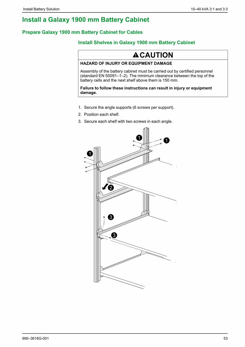
1. Secure the angle supports (6 screws per support).
2. Position each shelf.
3. Secure each shelf with two screws in each angle.
990–3618G-001 53
10–40 kVA 3:1 and 3:3 Install Battery Solution
Install Battery Circuit Breaker Kit in Galaxy 1900 mm BatteryCabinet
DANGERHAZARD OF ELECTRIC SHOCK, EXPLOSION, OR ARC FLASH
It is mandatory to protect the battery circuit with a circuit breaker equipped with acoil terminal and an auxiliary contact (min. 24 VDC).
Failure to follow these instructions will result in death or serious injury.
NOTE: For several battery cabinets installed, only one battery circuit breaker isnecessary. Temperature sensors must be installed to obtain battery warranty andto optimize battery lifetime.
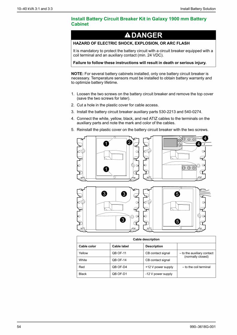
1. Loosen the two screws on the battery circuit breaker and remove the top cover(save the two screws for later).
2. Cut a hole in the plastic cover for cable access.
3. Install the battery circuit breaker auxiliary parts 530-2213 and 540-0274.
4. Connect the white, yellow, black, and red ATIZ cables to the terminals on theauxiliary parts and note the mark and color of the cables.
5. Reinstall the plastic cover on the battery circuit breaker with the two screws.
Cable description
Cable color Cable label Description
Yellow QB OF-11 CB contact signal – to the auxiliary contact(normally closed)
White QB OF-14 CB contact signal
Red QB OF-D4 +12 V power supply – to the coil terminal
Black QB OF-D1 -12 V power supply
54 990–3618G-001
Install Battery Solution 10–40 kVA 3:1 and 3:3
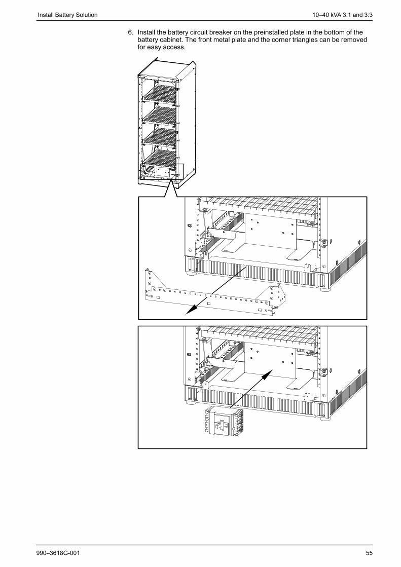
6. Install the battery circuit breaker on the preinstalled plate in the bottom of thebattery cabinet. The front metal plate and the corner triangles can be removedfor easy access.
990–3618G-001 55
10–40 kVA 3:1 and 3:3 Install Battery Solution
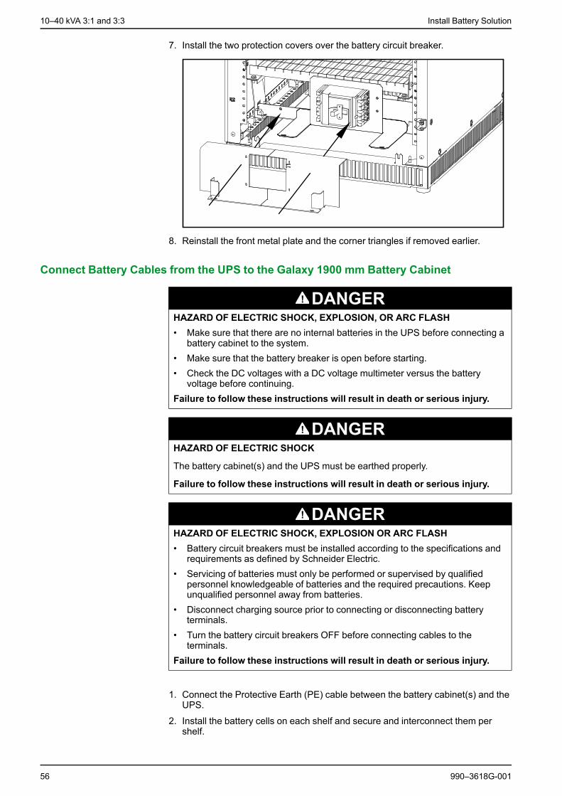
7. Install the two protection covers over the battery circuit breaker.
8. Reinstall the front metal plate and the corner triangles if removed earlier.
Connect Battery Cables from the UPS to the Galaxy 1900 mm Battery Cabinet
DANGERHAZARD OF ELECTRIC SHOCK, EXPLOSION, OR ARC FLASH• Make sure that there are no internal batteries in the UPS before connecting a
battery cabinet to the system.• Make sure that the battery breaker is open before starting.• Check the DC voltages with a DC voltage multimeter versus the battery
voltage before continuing.Failure to follow these instructions will result in death or serious injury.
DANGERHAZARD OF ELECTRIC SHOCK
The battery cabinet(s) and the UPS must be earthed properly.
Failure to follow these instructions will result in death or serious injury.
DANGERHAZARD OF ELECTRIC SHOCK, EXPLOSION OR ARC FLASH• Battery circuit breakers must be installed according to the specifications and
requirements as defined by Schneider Electric.• Servicing of batteries must only be performed or supervised by qualified
personnel knowledgeable of batteries and the required precautions. Keepunqualified personnel away from batteries.
• Disconnect charging source prior to connecting or disconnecting batteryterminals.
• Turn the battery circuit breakers OFF before connecting cables to theterminals.
Failure to follow these instructions will result in death or serious injury.
1. Connect the Protective Earth (PE) cable between the battery cabinet(s) and theUPS.
2. Install the battery cells on each shelf and secure and interconnect them pershelf.
56 990–3618G-001

Install Battery Solution 10–40 kVA 3:1 and 3:3
3. Interconnect all the battery shelves and then connect the battery cables (BAT+,BAT-, N) from the overall battery assembly to the battery circuit breaker in thebattery cabinet as shown in the illustration.
4. If more than one battery cabinet is installed: Connect the BAT+, BAT-, and Ncables (not provided) between the battery cabinets in a daisy chain.
5. Connect the battery cables (BAT+, BAT-, N) from the UPS to the battery circuitbreaker in the battery cabinet that will be connected to the UPS.
Front View of the Battery Cabinet
Install External Battery Temperature (ATIZ) and External Battery Breaker Signal betweenthe UPS and the Galaxy 1900 mm Battery Cabinet
NOTE: The ATIZ cable is for the external battery temperature detection signal.
NOTE: The battery cable is for the external battery breaker signal.
NOTE: The connection of signal cables is only applicable between the UPS andbattery cabinet 1.
1. Remove the right bottom protection cover on the classic battery cabinet.
2. Connect the cable terminal board to the supplied support sheet metal plate.
990–3618G-001 57
10–40 kVA 3:1 and 3:3 Install Battery Solution
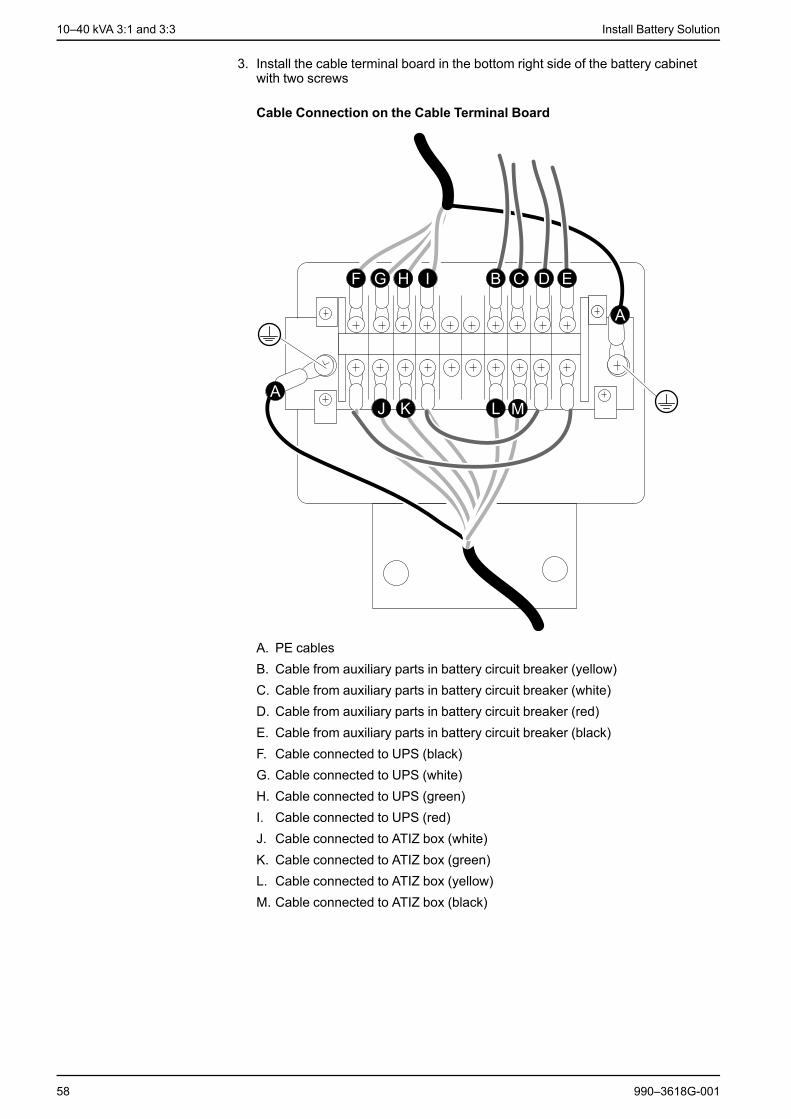
3. Install the cable terminal board in the bottom right side of the battery cabinetwith two screws
Cable Connection on the Cable Terminal Board
A. PE cablesB. Cable from auxiliary parts in battery circuit breaker (yellow)C. Cable from auxiliary parts in battery circuit breaker (white)D. Cable from auxiliary parts in battery circuit breaker (red)E. Cable from auxiliary parts in battery circuit breaker (black)F. Cable connected to UPS (black)G. Cable connected to UPS (white)H. Cable connected to UPS (green)I. Cable connected to UPS (red)J. Cable connected to ATIZ box (white)K. Cable connected to ATIZ box (green)L. Cable connected to ATIZ box (yellow)M. Cable connected to ATIZ box (black)
58 990–3618G-001

Install Battery Solution 10–40 kVA 3:1 and 3:3
4. Connect the four cables from the two auxiliary parts in the circuit breaker to thecable terminal board.
Cable description
Cable color Cable label Description
Yellow QB OF-11 CB contact signal – to the auxiliary contact(normally closed)
White QB OF-14 CB contact signal
Red QB OF-D4 +12 V power supply – to the coil terminal
Black QB OF-D1 -12 V power supply
5. Open the ATIZ board box and install it on the supplied support sheet metal platewith two screws.
6. Connect the four cables and the PE-cable from the cable terminal board to theATIZ board. Secure the joining cable with a cable tie.
Cable Connection in the ATIZ Board Box
7. Close the ATIZ board box.
8. Install the ATIZ board box in the top right side of the battery cabinet with twoscrews and secure the cable with cable ties down along the inside of the batterycabinet.
9. Run the combined battery breaker and ATIZ signal cable from the cableterminal board in the battery cabinet to the UPS.
990–3618G-001 59

10–40 kVA 3:1 and 3:3 Install Battery Solution
10.Connect the combined battery breaker and ATIZ signal cable to the UPS asshown and make sure to connect the cable with shielded layer to the screw onthe UPS.
NOTE: The cable(s) is routed the same way as the EPO cable.
Rear View of the UPS
11.Reinstall the right bottom protection cover on the battery cabinet.
Connect Battery and Signal Cables to Third Party Battery Solution
DANGERHAZARD OF ELECTRIC SHOCK, EXPLOSION, OR ARC FLASH• You must only use the UPS unit version intended for external batteries. A
third party battery solution must ONLY be used for a UPS configured withlong backup time charger (CLA).
• Before carrying out any of the below steps, you must make sure that the UPSunit and battery unit are powered off. See the operation manual (990-3619)shipped with the UPS unit on how to power off the UPS via the display.
• The external battery temperature detection kit (ATIZ) and the breaker signalmust be installed to ensure that the battery works normally. If the ATIZ kit isnot installed, the UPS will report a temperature fault with a permanent alarm.Only a Schneider Electric field service engineer can disable this alarm. Theconsequence of not installing the ATIZ kit is that the unit does not have atemperature compensation function, and this will also affect the battery life, ifthe battery is installed in a room that is not appropriately air-cooled.
• The cables must have shielded layer, and they must be connected to theUPS and the external third party battery solution. If not, the unit will face EMCand shutdown problems.
• The battery breaker must be equipped with a coil terminal and an auxiliarycontact (min. 24 VDC).
• Schneider Electric is not responsible for the wiring of external third partybatteries.
Failure to follow these instructions will result in death or serious injury.
60 990–3618G-001

Install Battery Solution 10–40 kVA 3:1 and 3:3
NOTE: A maximum of two battery cabinets can be connected to the UPS (onebattery cabinet with a circuit breaker plus one cabinet without a circuit breaker, asonly one breaker is supported) by a batch cable between the UPS and the circuitbreaker in the battery cabinet.
1. Prepare one or two shielded cables with 4 twisted pairs for the ATIZ contact andthe battery circuit breaker. All shielded cables must be wound three timesaround a High permeability NiZn Ferrite placed as close to the UPS as possible.
NOTE: +/-12 V power supply is common for ATIZ and the auxiliary coil of thebattery circuit breaker.
Rear View of the UPS
2. Install the ATIZ signal board in the third party battery solution.
3. Connect the ATIZ signal cable to the ATIZ board in the third party batterysolution (see the below table for cable description).
Cable description
Cable color Cable label Description
Black -12 -12 V power supply – to the ATIZ contact
White BC- BC- (ATIZ signal)
Green BC+ BC+ (ATIZ signal)
Red +12 +12 V power supply
Green-yellow Grounding
NOTE: If a battery breaker has not been installed in the third party batterysolution, install one now. The battery breaker must be equipped with a coilterminal and an auxiliary contact (min. 24 VDC). If there is no undervoltage coilterminal in the battery circuit breaker, then the UPS cannot open the batterycircuit breaker when necessary (EPO). If there is no auxiliary contact in thebattery circuit breaker, then the UPS will report a battery circuit breaker openfault with a permanent alarm.
DANGERHAZARD OF ELECTRIC SHOCK, EXPLOSION, OR ARC FLASH
The battery circuit breaker must be open (in the OFF position) before youconnect the cables.
Failure to follow these instructions will result in death or serious injury.
990–3618G-001 61
10–40 kVA 3:1 and 3:3 Install Battery Solution
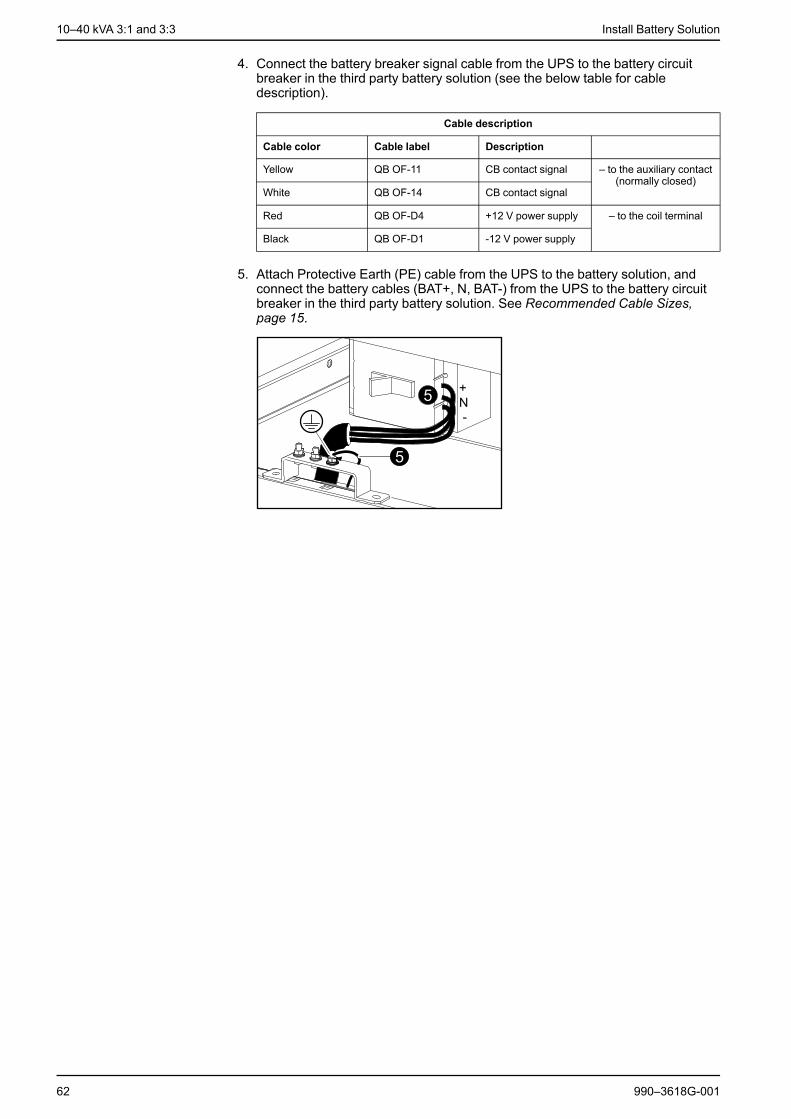
4. Connect the battery breaker signal cable from the UPS to the battery circuitbreaker in the third party battery solution (see the below table for cabledescription).
Cable description
Cable color Cable label Description
Yellow QB OF-11 CB contact signal – to the auxiliary contact(normally closed)
White QB OF-14 CB contact signal
Red QB OF-D4 +12 V power supply – to the coil terminal
Black QB OF-D1 -12 V power supply
5. Attach Protective Earth (PE) cable from the UPS to the battery solution, andconnect the battery cables (BAT+, N, BAT-) from the UPS to the battery circuitbreaker in the third party battery solution. See Recommended Cable Sizes,page 15.
62 990–3618G-001
Connect the UPS Signal Cables 10–40 kVA 3:1 and 3:3
Connect the UPS Signal Cables
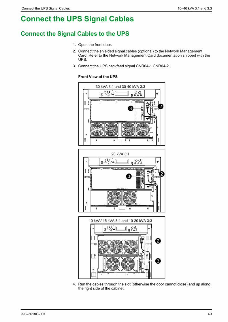
Connect the Signal Cables to the UPS1. Open the front door.
2. Connect the shielded signal cables (optional) to the Network ManagementCard. Refer to the Network Management Card documentation shipped with theUPS.
3. Connect the UPS backfeed signal CNR04-1 CNR04-2.
Front View of the UPS
4. Run the cables through the slot (otherwise the door cannot close) and up alongthe right side of the cabinet.
990–3618G-001 63
10–40 kVA 3:1 and 3:3 Connect the UPS Signal Cables
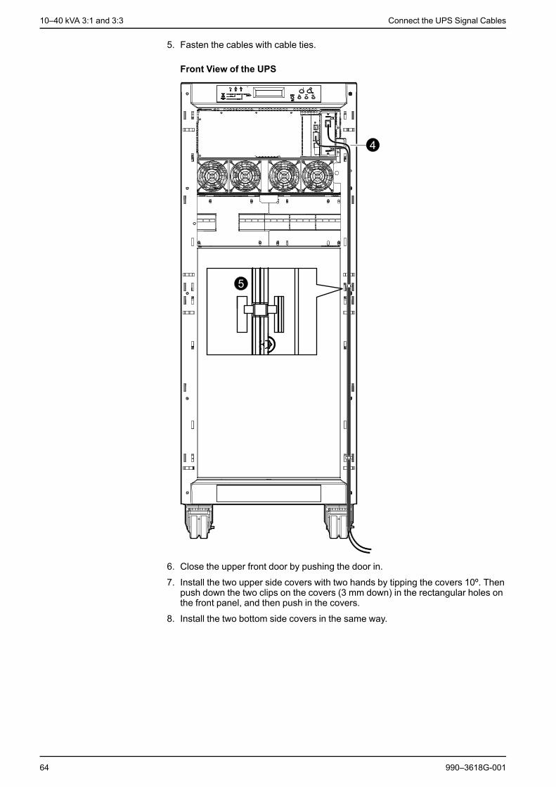
5. Fasten the cables with cable ties.
Front View of the UPS
6. Close the upper front door by pushing the door in.
7. Install the two upper side covers with two hands by tipping the covers 10º. Thenpush down the two clips on the covers (3 mm down) in the rectangular holes onthe front panel, and then push in the covers.
8. Install the two bottom side covers in the same way.
64 990–3618G-001

Connect the UPS Signal Cables 10–40 kVA 3:1 and 3:3
9. Connect the cables to your computer interface network.
Front View of the UPS
Connect the EPO Cable to the UPS
DANGERHAZARD OF ELECTRIC SHOCK, EXPLOSION, OR ARC FLASH
The cables must have a shielded layer, and the shielded layer must beconnected to grounding on both the UPS side and the customer side.
Failure to follow these instructions will result in death or serious injury.
NOTE: A jumper must be added if no EPO cable is connected.
990–3618G-001 65
10–40 kVA 3:1 and 3:3 Connect the UPS Signal Cables
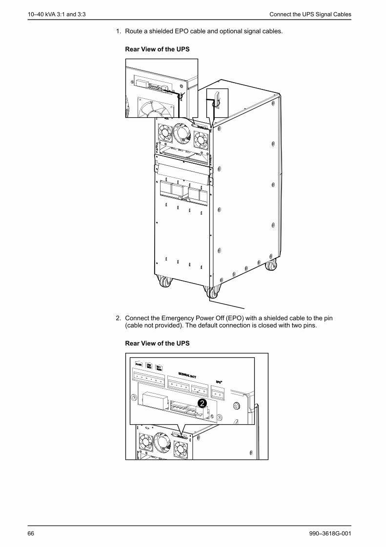
1. Route a shielded EPO cable and optional signal cables.
Rear View of the UPS
2. Connect the Emergency Power Off (EPO) with a shielded cable to the pin(cable not provided). The default connection is closed with two pins.
Rear View of the UPS
66 990–3618G-001
Connect the UPS Signal Cables 10–40 kVA 3:1 and 3:3
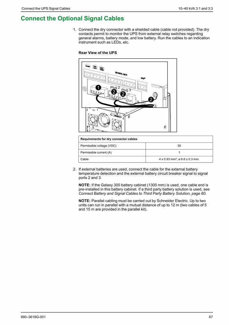
Connect the Optional Signal Cables1. Connect the dry connector with a shielded cable (cable not provided). The dry
contacts permit to monitor the UPS from external relay switches regardinggeneral alarms, battery mode, and low battery. Run the cables to an indicationinstrument such as LEDs, etc.
Rear View of the UPS
Requirements for dry connector cables
Permissible voltage (VDC) 30
Permissible current (A) 1
Cable 4 x 0.93 mm², ø 6.6 ± 0.3 mm.
2. If external batteries are used, connect the cable for the external batterytemperature detection and the external battery circuit breaker signal to signalports 2 and 3.
NOTE: If the Galaxy 300 battery cabinet (1300 mm) is used, one cable end ispre-installed in this battery cabinet. If a third party battery solution is used, seeConnect Battery and Signal Cables to Third Party Battery Solution, page 60.
NOTE: Parallel cabling must be carried out by Schneider Electric. Up to twounits can run in parallel with a mutual distance of up to 12 m (two cables of 5and 15 m are provided in the parallel kit).
990–3618G-001 67

10–40 kVA 3:1 and 3:3 Checklist after Installation
Checklist after Installation
UPS• Check that the power wiring is torqued correctly.• Verify clockwise phase-rotation (L1, L2, L3) and make sure that a neutral
connection is present.• Leave a wiring diagram on site for service personnel.• Reinstall all wiring access panels.• Make sure that all battery breakers on the UPS unit are in the OFF (opened)
position.
Battery Solution• Check that the power wiring is torqued as recommended by the battery vendor.• Verify the polarity of battery cable connection (BAT+, N and BAT-).• Leave a wiring diagram on site for service personnel.• Reinstall all wiring access panels.• Make sure that all battery breakers on the battery solution are in the OFF
(opened) position.• Install the two protection covers over the battery circuit breaker on the Galaxy
1900 mm battery cabinet.
68 990–3618G-001


Printed in.Schneider Electric
Schneider Electric35 rue Joseph Monier92500 Rueil MalmasonFrance
+ 33 (0) 1 41 29 70 00
www.schneider-electric.com
As standards, specifications, and design change from time to time,please ask for confirmation of the information given in this publication.
© 2012 – 2016 Schneider Electric. All rights reserved.
990–3618G-001


![Mugen Power 2000mAh Extended Battery for Samsung Galaxy Nexus (GT-i9250) [HLI-i9250SL]](https://img.pdfslide.us/doc/110x75/55ce6710bb61eb33358b464a/mugen-power-2000mah-extended-battery-for-samsung-galaxy-nexus-gt-i9250-hli-i9250sl.jpg)