Embed Size (px)
Citation preview

ISSUE 005
GainJet Aviation Flight Safety Magazine
Editorial
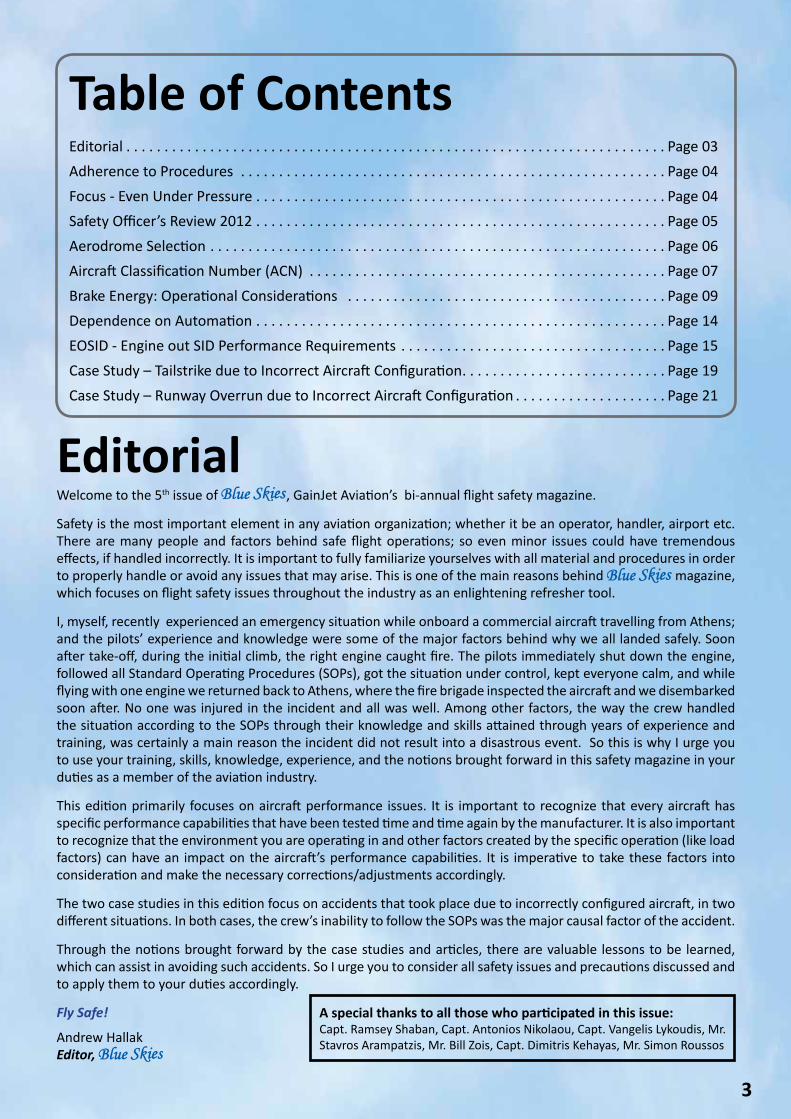
Table of Contents
Welcome to the 5th issue of , GainJet Aviation’s bi-annual flight safety magazine.
Safety is the most important element in any aviation organization; whether it be an operator, handler, airport etc. There are many people and factors behind safe flight operations; so even minor issues could have tremendous effects, if handled incorrectly. It is important to fully familiarize yourselves with all material and procedures in order to properly handle or avoid any issues that may arise. This is one of the main reasons behind magazine, which focuses on flight safety issues throughout the industry as an enlightening refresher tool.
I, myself, recently experienced an emergency situation while onboard a commercial aircraft travelling from Athens; and the pilots’ experience and knowledge were some of the major factors behind why we all landed safely. Soon after take-off, during the initial climb, the right engine caught fire. The pilots immediately shut down the engine, followed all Standard Operating Procedures (SOPs), got the situation under control, kept everyone calm, and while flying with one engine we returned back to Athens, where the fire brigade inspected the aircraft and we disembarked soon after. No one was injured in the incident and all was well. Among other factors, the way the crew handled the situation according to the SOPs through their knowledge and skills attained through years of experience and training, was certainly a main reason the incident did not result into a disastrous event. So this is why I urge you to use your training, skills, knowledge, experience, and the notions brought forward in this safety magazine in your duties as a member of the aviation industry.
This edition primarily focuses on aircraft performance issues. It is important to recognize that every aircraft has specific performance capabilities that have been tested time and time again by the manufacturer. It is also important to recognize that the environment you are operating in and other factors created by the specific operation (like load factors) can have an impact on the aircraft’s performance capabilities. It is imperative to take these factors into consideration and make the necessary corrections/adjustments accordingly.
The two case studies in this edition focus on accidents that took place due to incorrectly configured aircraft, in two different situations. In both cases, the crew’s inability to follow the SOPs was the major causal factor of the accident.
Through the notions brought forward by the case studies and articles, there are valuable lessons to be learned, which can assist in avoiding such accidents. So I urge you to consider all safety issues and precautions discussed and to apply them to your duties accordingly.
Fly Safe!
Andrew HallakEditor,
Editorial . . . . . . . . . . . . . . . . . . . . . . . . . . . . . . . . . . . . . . . . . . . . . . . . . . . . . . . . . . . . . . . . . . . . . . . Page 03Adherence to Procedures . . . . . . . . . . . . . . . . . . . . . . . . . . . . . . . . . . . . . . . . . . . . . . . . . . . . . . . . Page 04Focus - Even Under Pressure . . . . . . . . . . . . . . . . . . . . . . . . . . . . . . . . . . . . . . . . . . . . . . . . . . . . . . Page 04Safety Officer’s Review 2012 . . . . . . . . . . . . . . . . . . . . . . . . . . . . . . . . . . . . . . . . . . . . . . . . . . . . . . Page 05Aerodrome Selection . . . . . . . . . . . . . . . . . . . . . . . . . . . . . . . . . . . . . . . . . . . . . . . . . . . . . . . . . . . . Page 06Aircraft Classification Number (ACN) . . . . . . . . . . . . . . . . . . . . . . . . . . . . . . . . . . . . . . . . . . . . . . . Page 07Brake Energy: Operational Considerations . . . . . . . . . . . . . . . . . . . . . . . . . . . . . . . . . . . . . . . . . . Page 09Dependence on Automation . . . . . . . . . . . . . . . . . . . . . . . . . . . . . . . . . . . . . . . . . . . . . . . . . . . . . . Page 14EOSID - Engine out SID Performance Requirements . . . . . . . . . . . . . . . . . . . . . . . . . . . . . . . . . . . Page 15Case Study – Tailstrike due to Incorrect Aircraft Configuration. . . . . . . . . . . . . . . . . . . . . . . . . . . Page 19Case Study – Runway Overrun due to Incorrect Aircraft Configuration . . . . . . . . . . . . . . . . . . . . Page 21
3
A special thanks to all those who participated in this issue:Capt. Ramsey Shaban, Capt. Antonios Nikolaou, Capt. Vangelis Lykoudis, Mr. Stavros Arampatzis, Mr. Bill Zois, Capt. Dimitris Kehayas, Mr. Simon Roussos
As a pilot for so many years, I’ve had my fair share of experiences and lessons learned – but that’s what makes us better. While flying for a previous VIP operation, I recall one particular lesson I learned when departing out of Santiago, Spain. We were two Captains on this particular flight travelling with a prominent VIP passenger. It all started when our VIP passengers decided to arrive to the aircraft earlier than planned and before we had even started our pre-flight work.
Due to the nature of the flight and the urgency to depart quickly, I requested from the other Captain (who was acting as a co-pilot on this sector) to complete the walk around and remove all pins and covers. We completed the pre-flight and managed to start up and taxi within a very short time. Take off role was normal until we reached 80 knots, our cross speed check point. The co-pilot announced his
speed was reading much less and was not increasing. So we decided to abandon take off. While still taxing, we reviewed quickly what could have gone wrong and decided to check the number of our pitot covers. It quickly became evident that one was missing and it was the culprit for losing our speed indication on the right side! Embarrassingly, the cover was removed and the flight departed normally. Fortunately the lesson learned the hard way but with little damage was: never be rushed into doing your check list procedures!
Adherence to Procedures
Focus – Even Under PressureI would first like to introduce myself as the new Accountable Manager at GainJet. My background as an aviator dates back to the early 70’s. During my career I have witnessed major technological advances, from B707 and B747 AFM graphs to applying modern Airbus and Gulfstream optimized performance software. Stress is a key contributing factor for errors and mistakes. Even with modern electronic flight bags and flight management computers, the threat of human error still exists. Erroneous data entries will not be rejected as long as they fall within certain tolerances. These errors may later become a contributing factor to a serious incident.
On one occasion, I can recall ATC advising us to expedite our start while ground staff was informing us about a missing passenger; and as the Captain was reviewing the load sheet figures, the ramp agent was asking for the delay code. During this occasion, it was also necessary to make last minute adjustments for contaminated runway conditions. Operating under the so called “Rush Syndrome” has been a contributing factor to several serious incidents
and accidents. Pilots are expected to typically increase the rate of information processing in a short amount of time – this decreases the amount of time spent evaluating response options. To cope with high time pressure contexts, pilots engage in excessive information shedding, inefficient information processing, random response choices based on temporary salient characteristics, and overlooking relevant information. Consequently, the pilot’s performance suffers. Therefore in pre-flight and taxi-out phases, where there are high workload operations, hurry-up errors were seen to most likely occur. Remember:Performance planning is vital, and allowing oneself to be rushed increases chances for mistakes to happen and go unnoticed.
By Captain Antonios NikolaouAccountable ManagerGainJet Aviation S.A
By Captain Ramsey ShabanPresidentGainJet Aviation S.A
4
Safety Officer’s Review 2012It’s a known fact that the majority of incidents and accidents are caused by human error or negligence. So we’ve targeted this specific factor in our training and focus.
GainJet’s Safety and Flight Ops departments are constantly collaborating together in order to minimize the chances of an occurrence, especially that associated with human factors.
We have put an emphasis on Crew Recourse Management (CRM), which aims to create better cooperation between flight crew, cabin crew, ground staff, and ATC.
Using past safety studies and modern safety training tactics we have created a highly efficient
training programme, which aims to reduce such incidents.
We have also introduced a Safety Management System, which allows us to assess and mitigate any risks, thus ensuring safer flight operations.
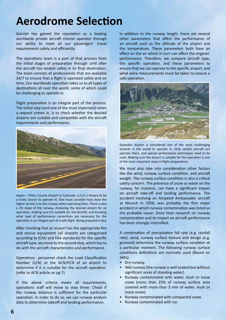
Through this intensified focus on CRM, GainJet has been able to minimize the number of incidents based on human factors; as can be seen by the comparison of the below incident charts for 2011-2012.
As you can see from the charts below, human related incidents have decreased, as GainJet focuses its training on CRM and SOP adherence.
Please always remember that safety is our top priority.
By Captain Vangelis LykoudisFlight Safety Officer
5
2012 2011
MONTH TYPE OF INCIDENT MONTH TYPE OF INCIDENT
Jan Human May TechnicalJan Weather May Human
Jan Human May Human
Jan Technical November Human
May Technical December Human
Sep Technical December Human
Nov Human December Technical
0
1
2
3
4
5
6
HUMAN
TECHNICAL
OTHER
2011 2012
Aerodrome Selection
6
GainJet has gained the reputation as a leading worldwide private aircraft charter operator through our ability to meet all our passengers’ travel requirements safely and efficiently. The operations team is a part of that process from the initial stages of preparation through until after the aircraft has landed safely in its final destination. The team consists of professionals that are available 24/7 to ensure that a flight is operated safely and on time. Our worldwide operation takes us to all types of destinations all over the world, some of which could be challenging to operate in. Flight preparation is an integral part of the process. The initial step (and one of the most important) when a request comes in, is to check whether the desired airports are suitable and compatible with the aircraft requirements and performance.
In addition to the runway length, there are several other parameters that affect the performance of an aircraft such as the altitude of the airport and the temperature. These parameters both have an effect on the air which in turn can affect the engines’ performance. Therefore, we compare aircraft type, the specific operation, and these parameters to ensure that we can operate to the specific airport, and what extra measurements must be taken to ensure a safe operation.
After checking that an airport has the appropriate fire and rescue equipment (all airports are categorized according to ICAO and FAA standards) for the specific aircraft type, we move to the second step, which has to do with the aircraft characteristics and performance. Operations personnel check the Load Classification Number (LCN) or the ACN/PCN of an airport to determine if it is suitable for the aircraft operation. (refer to ACN article on pg 7) If the above criteria meets all requirements, operations staff will move to step three: Check if the runway distance is sufficient for the particular operation. In order to do so, we use runway analysis data to determine takeoff and landing performance.
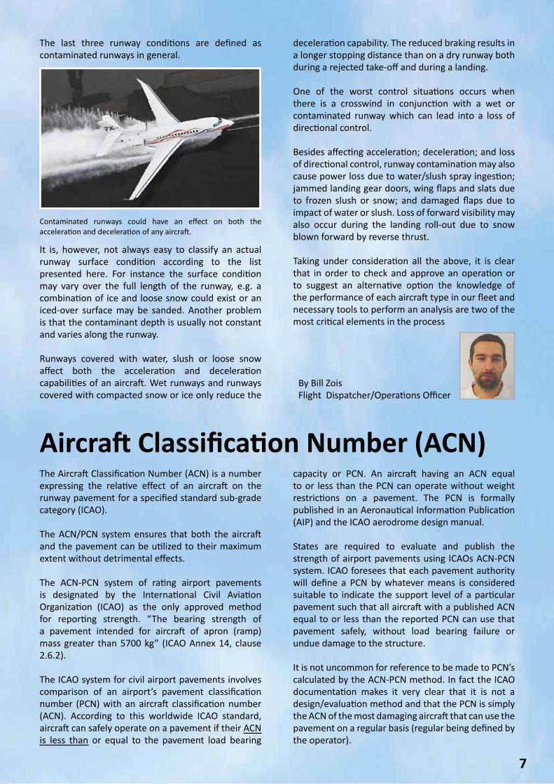
Aspen – Pitkin County Airport in Colorado, U.S.A is known to be a tricky airport to operate in. One must consider how close the higher terrain is to the runway when operating here. There is also a 2% slope of the runway. Analyzing the desired airport for an operation, making sure it’s suitable for the aircraft, and knowing what type of performance corrections are necessary for the operation is an integral part of a safe flight. Being prepared is key.
Samedan Airport is considered one of the most challenging airports in the world to operate in. Only certain aircraft can operate there, and special performance techniques need to be used. Making sure the airport is suitable for the operation is one of the most important steps in flight preparations.
We must also take into consideration other factors like the wind, runway surface condition, and aircraft weight. The runway surface condition is also a critical safety concern. The presence of snow or water on the runway, for instance, can have a significant impact on aircraft take-off and landing performance. The accident involving an Airspeed Ambassador aircraft at Munich in 1958, was probably the first major accident in which runway contamination was listed as the probable cause. Since then research on runway contamination and its impact on aircraft performance has been strongly intensified. A combination of precipitation fall rate (e.g. rainfall rate), wind, runway surface texture and design (e.g. grooved) determine the runway surface condition at a particular moment. The following runway surface conditions definitions are normally used (Based on JARs):• Dry runway.• Wet runway (the runway is well soaked but without
significant areas of standing water).• Runway contaminated with water, slush or loose
snow (more than 25% of runway surface area covered with more than 3 mm of water, slush or loose snow).
• Runway contaminated with compacted snow.• Runway contaminated with ice.
Aircraft Classification Number (ACN)
7
The Aircraft Classification Number (ACN) is a number expressing the relative effect of an aircraft on the runway pavement for a specified standard sub-grade category (ICAO).
The ACN/PCN system ensures that both the aircraft and the pavement can be utilized to their maximum extent without detrimental effects.
The ACN-PCN system of rating airport pavements is designated by the International Civil Aviation Organization (ICAO) as the only approved method for reporting strength. “The bearing strength of a pavement intended for aircraft of apron (ramp) mass greater than 5700 kg” (ICAO Annex 14, clause 2.6.2).
The ICAO system for civil airport pavements involves comparison of an airport’s pavement classification number (PCN) with an aircraft classification number (ACN). According to this worldwide ICAO standard, aircraft can safely operate on a pavement if their ACN is less than or equal to the pavement load bearing
capacity or PCN. An aircraft having an ACN equal to or less than the PCN can operate without weight restrictions on a pavement. The PCN is formally published in an Aeronautical Information Publication (AIP) and the ICAO aerodrome design manual.
States are required to evaluate and publish the strength of airport pavements using ICAOs ACN-PCN system. ICAO foresees that each pavement authority will define a PCN by whatever means is considered suitable to indicate the support level of a particular pavement such that all aircraft with a published ACN equal to or less than the reported PCN can use that pavement safely, without load bearing failure or undue damage to the structure.
It is not uncommon for reference to be made to PCN’s calculated by the ACN-PCN method. In fact the ICAO documentation makes it very clear that it is not a design/evaluation method and that the PCN is simply the ACN of the most damaging aircraft that can use the pavement on a regular basis (regular being defined by the operator).
Contaminated runways could have an effect on both the acceleration and deceleration of any aircraft.
The last three runway conditions are defined as contaminated runways in general.
deceleration capability. The reduced braking results in a longer stopping distance than on a dry runway both during a rejected take-off and during a landing.
One of the worst control situations occurs when there is a crosswind in conjunction with a wet or contaminated runway which can lead into a loss of directional control.
Besides affecting acceleration; deceleration; and loss of directional control, runway contamination may also cause power loss due to water/slush spray ingestion; jammed landing gear doors, wing flaps and slats due to frozen slush or snow; and damaged flaps due to impact of water or slush. Loss of forward visibility may also occur during the landing roll-out due to snow blown forward by reverse thrust. Taking under consideration all the above, it is clear that in order to check and approve an operation or to suggest an alternative option the knowledge of the performance of each aircraft type in our fleet and necessary tools to perform an analysis are two of the most critical elements in the process
By Bill ZoisFlight Dispatcher/Operations Officer
It is, however, not always easy to classify an actual runway surface condition according to the list presented here. For instance the surface condition may vary over the full length of the runway, e.g. a combination of ice and loose snow could exist or an iced-over surface may be sanded. Another problem is that the contaminant depth is usually not constant and varies along the runway. Runways covered with water, slush or loose snow affect both the acceleration and deceleration capabilities of an aircraft. Wet runways and runways covered with compacted snow or ice only reduce the
8
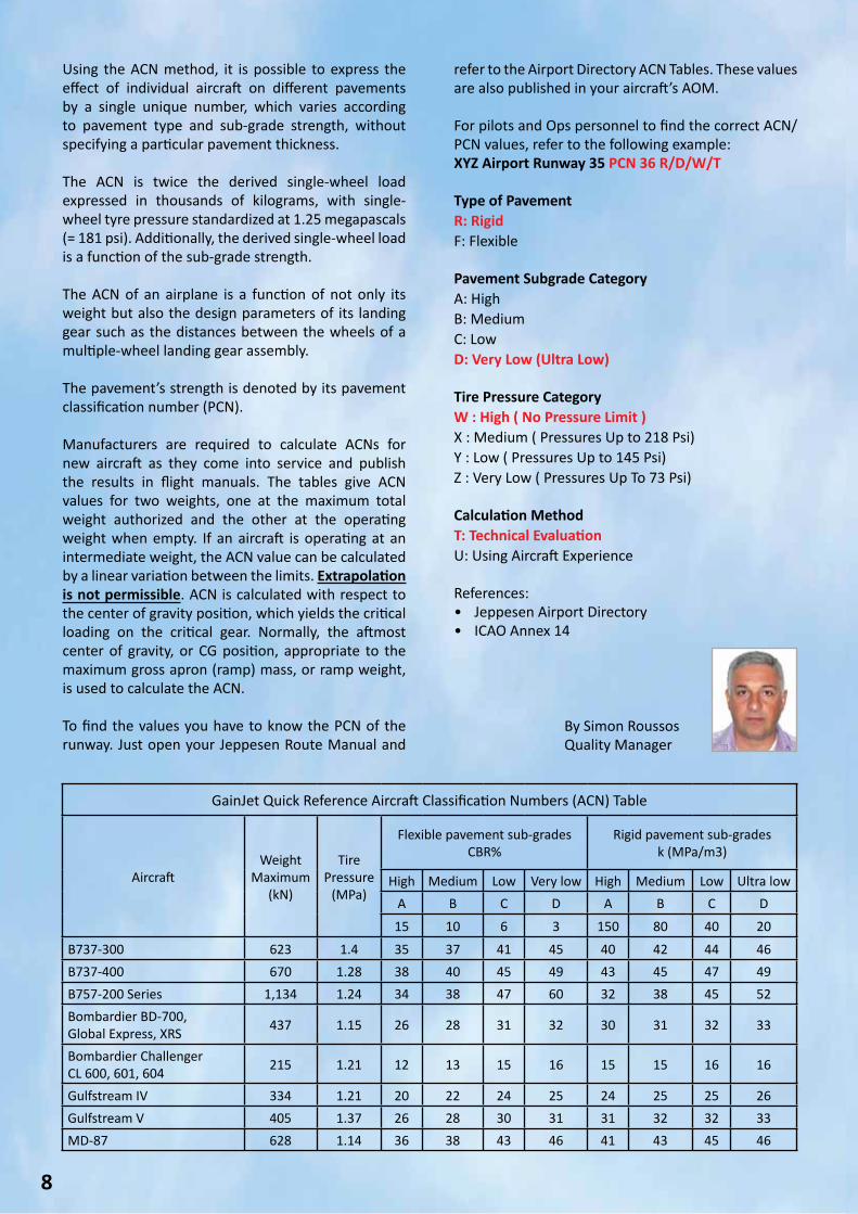
Using the ACN method, it is possible to express the effect of individual aircraft on different pavements by a single unique number, which varies according to pavement type and sub-grade strength, without specifying a particular pavement thickness.
The ACN is twice the derived single-wheel load expressed in thousands of kilograms, with single-wheel tyre pressure standardized at 1.25 megapascals (= 181 psi). Additionally, the derived single-wheel load is a function of the sub-grade strength.
The ACN of an airplane is a function of not only its weight but also the design parameters of its landing gear such as the distances between the wheels of a multiple-wheel landing gear assembly.
The pavement’s strength is denoted by its pavement classification number (PCN).
Manufacturers are required to calculate ACNs for new aircraft as they come into service and publish the results in flight manuals. The tables give ACN values for two weights, one at the maximum total weight authorized and the other at the operating weight when empty. If an aircraft is operating at an intermediate weight, the ACN value can be calculated by a linear variation between the limits. Extrapolation is not permissible. ACN is calculated with respect to the center of gravity position, which yields the critical loading on the critical gear. Normally, the aftmost center of gravity, or CG position, appropriate to the maximum gross apron (ramp) mass, or ramp weight, is used to calculate the ACN.
To find the values you have to know the PCN of the runway. Just open your Jeppesen Route Manual and
refer to the Airport Directory ACN Tables. These values are also published in your aircraft’s AOM.
For pilots and Ops personnel to find the correct ACN/PCN values, refer to the following example:XYZ Airport Runway 35 PCN 36 R/D/W/T
Type of PavementR: RigidF: Flexible
Pavement Subgrade CategoryA: HighB: MediumC: LowD: Very Low (Ultra Low)
Tire Pressure CategoryW : High ( No Pressure Limit )X : Medium ( Pressures Up to 218 Psi) Y : Low ( Pressures Up to 145 Psi) Z : Very Low ( Pressures Up To 73 Psi)
Calculation MethodT: Technical EvaluationU: Using Aircraft Experience
References:• Jeppesen Airport Directory• ICAO Annex 14
By Simon RoussosQuality Manager
GainJet Quick Reference Aircraft Classification Numbers (ACN) Table
AircraftWeight
Maximum (kN)
Tire Pressure
(MPa)
Flexible pavement sub-gradesCBR%
Rigid pavement sub-gradesk (MPa/m3)
High Medium Low Very low High Medium Low Ultra lowA B C D A B C D
15 10 6 3 150 80 40 20
B737-300 623 1.4 35 37 41 45 40 42 44 46B737-400 670 1.28 38 40 45 49 43 45 47 49B757-200 Series 1,134 1.24 34 38 47 60 32 38 45 52Bombardier BD-700,Global Express, XRS 437 1.15 26 28 31 32 30 31 32 33
Bombardier ChallengerCL 600, 601, 604 215 1.21 12 13 15 16 15 15 16 16
Gulfstream IV 334 1.21 20 22 24 25 24 25 25 26Gulfstream V 405 1.37 26 28 30 31 31 32 32 33MD-87 628 1.14 36 38 43 46 41 43 45 46
9
Brake Energy: Operational ConsiderationsIntroductionBrake energy considerations are a factor in a relatively small number of takeoff and landing situations. New airplanes have improved certification methods for wheels, tyres, and brakes. They have additional protections, which older airplane certifications did not include. Brake energy limitations are not well understood by many engineers, pilots, and dispatchers. Unfortunately, incidents continue to occur, indicating less than complete understanding of this issue. BrakesThe primary function of a brake is to generate stopping force.
Braking force is generated when the rotors and stators are squeezed together by application of hydraulic pressure to create friction. Hydraulic pressure is applied to the brakes either by the auto-brake system or manually when the flight crew pushes the brake pedals (tops of the rudder pedals). Left and right brakes can be applied independently, if desired by the flight crew, to aid in directional control.
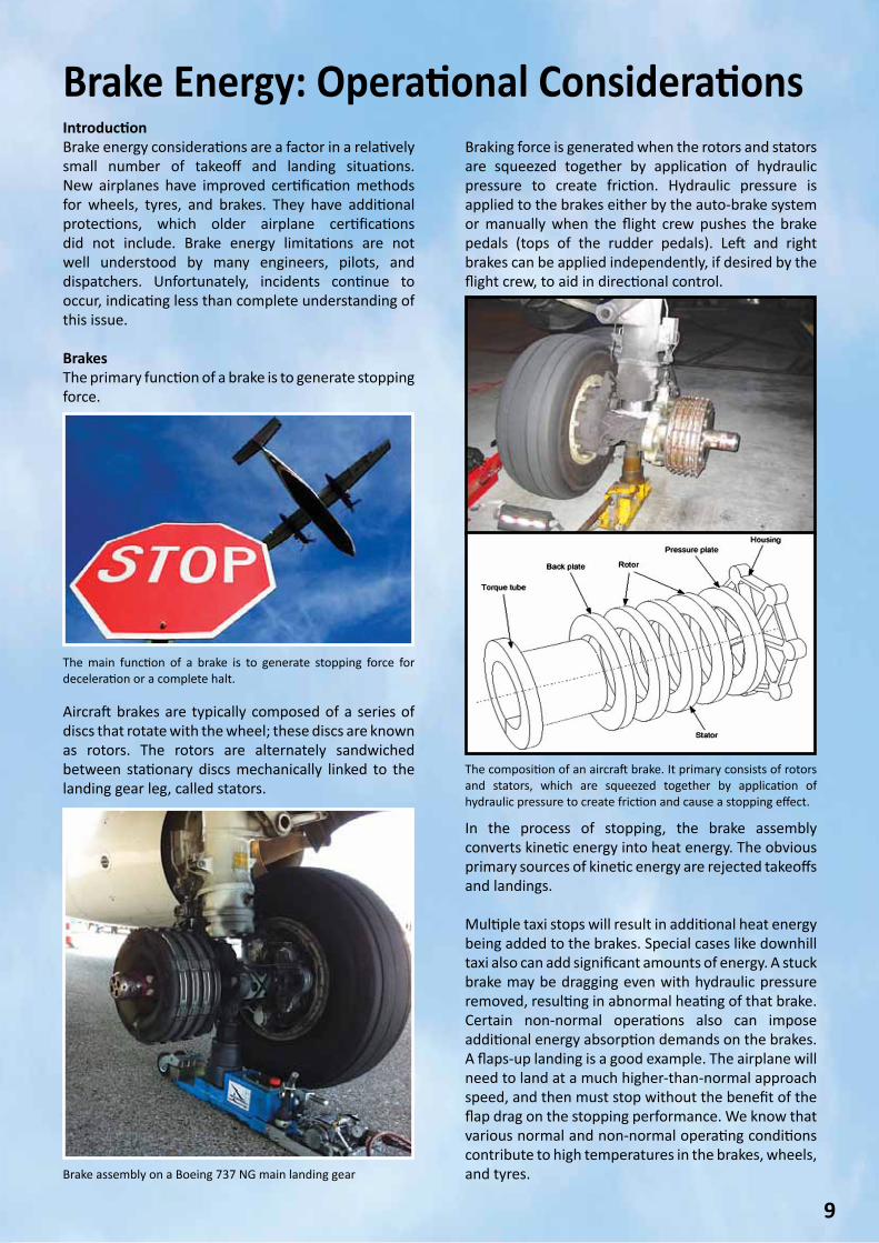
The composition of an aircraft brake. It primary consists of rotors and stators, which are squeezed together by application of hydraulic pressure to create friction and cause a stopping effect.
The main function of a brake is to generate stopping force for deceleration or a complete halt.
Brake assembly on a Boeing 737 NG main landing gear
In the process of stopping, the brake assembly converts kinetic energy into heat energy. The obvious primary sources of kinetic energy are rejected takeoffs and landings. Multiple taxi stops will result in additional heat energy being added to the brakes. Special cases like downhill taxi also can add significant amounts of energy. A stuck brake may be dragging even with hydraulic pressure removed, resulting in abnormal heating of that brake. Certain non-normal operations also can impose additional energy absorption demands on the brakes. A flaps-up landing is a good example. The airplane will need to land at a much higher-than-normal approach speed, and then must stop without the benefit of the flap drag on the stopping performance. We know that various normal and non-normal operating conditions contribute to high temperatures in the brakes, wheels, and tyres.
Aircraft brakes are typically composed of a series of discs that rotate with the wheel; these discs are known as rotors. The rotors are alternately sandwiched between stationary discs mechanically linked to the landing gear leg, called stators.
10
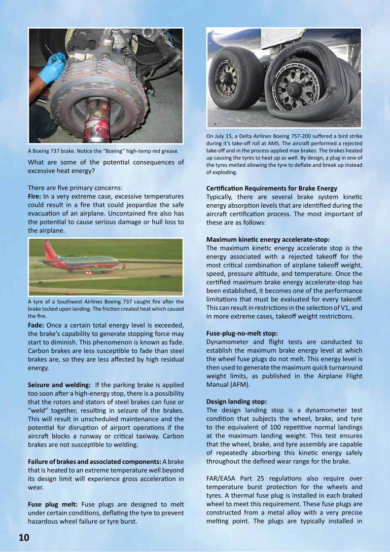
A Boeing 737 brake. Notice the “Boeing” high-temp red grease.
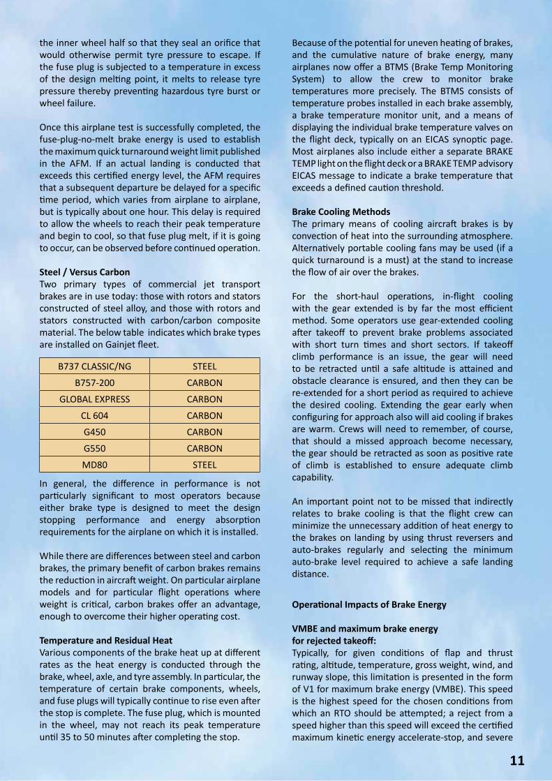
A tyre of a Southwest Airlines Boeing 737 caught fire after the brake locked upon landing. The friction created heat which caused the fire.
On July 15, a Delta Airlines Boeing 757-200 suffered a bird strike during it’s take-off roll at AMS. The aircraft performed a rejected take-off and in the process applied max brakes. The brakes heated up causing the tyres to heat up as well. By design, a plug in one of the tyres melted allowing the tyre to deflate and break up instead of exploding.
What are some of the potential consequences of excessive heat energy?
There are five primary concerns:Fire: In a very extreme case, excessive temperatures could result in a fire that could jeopardize the safe evacuation of an airplane. Uncontained fire also has the potential to cause serious damage or hull loss to the airplane.
Certification Requirements for Brake EnergyTypically, there are several brake system kinetic energy absorption levels that are identified during the aircraft certification process. The most important of these are as follows: Maximum kinetic energy accelerate-stop: The maximum kinetic energy accelerate stop is the energy associated with a rejected takeoff for the most critical combination of airplane takeoff weight, speed, pressure altitude, and temperature. Once the certified maximum brake energy accelerate-stop has been established, it becomes one of the performance limitations that must be evaluated for every takeoff. This can result in restrictions in the selection of V1, and in more extreme cases, takeoff weight restrictions. Fuse-plug-no-melt stop: Dynamometer and flight tests are conducted to establish the maximum brake energy level at which the wheel fuse plugs do not melt. This energy level is then used to generate the maximum quick turnaround weight limits, as published in the Airplane Flight Manual (AFM). Design landing stop: The design landing stop is a dynamometer test condition that subjects the wheel, brake, and tyre to the equivalent of 100 repetitive normal landings at the maximum landing weight. This test ensures that the wheel, brake, and tyre assembly are capable of repeatedly absorbing this kinetic energy safely throughout the defined wear range for the brake.
FAR/EASA Part 25 regulations also require over temperature burst protection for the wheels and tyres. A thermal fuse plug is installed in each braked wheel to meet this requirement. These fuse plugs are constructed from a metal alloy with a very precise melting point. The plugs are typically installed in
Fade: Once a certain total energy level is exceeded, the brake’s capability to generate stopping force may start to diminish. This phenomenon is known as fade. Carbon brakes are less susceptible to fade than steel brakes are, so they are less affected by high residual energy.
Seizure and welding: If the parking brake is applied too soon after a high-energy stop, there is a possibility that the rotors and stators of steel brakes can fuse or “weld” together, resulting in seizure of the brakes. This will result in unscheduled maintenance and the potential for disruption of airport operations if the aircraft blocks a runway or critical taxiway. Carbon brakes are not susceptible to welding.
Failure of brakes and associated components: A brake that is heated to an extreme temperature well beyond its design limit will experience gross acceleration in wear.
Fuse plug melt: Fuse plugs are designed to melt under certain conditions, deflating the tyre to prevent hazardous wheel failure or tyre burst.
11
the inner wheel half so that they seal an orifice that would otherwise permit tyre pressure to escape. If the fuse plug is subjected to a temperature in excess of the design melting point, it melts to release tyre pressure thereby preventing hazardous tyre burst or wheel failure.
Once this airplane test is successfully completed, the fuse-plug-no-melt brake energy is used to establish the maximum quick turnaround weight limit published in the AFM. If an actual landing is conducted that exceeds this certified energy level, the AFM requires that a subsequent departure be delayed for a specific time period, which varies from airplane to airplane, but is typically about one hour. This delay is required to allow the wheels to reach their peak temperature and begin to cool, so that fuse plug melt, if it is going to occur, can be observed before continued operation.
Steel / Versus CarbonTwo primary types of commercial jet transport brakes are in use today: those with rotors and stators constructed of steel alloy, and those with rotors and stators constructed with carbon/carbon composite material. The below table indicates which brake types are installed on Gainjet fleet.
In general, the difference in performance is not particularly significant to most operators because either brake type is designed to meet the design stopping performance and energy absorption requirements for the airplane on which it is installed. While there are differences between steel and carbon brakes, the primary benefit of carbon brakes remains the reduction in aircraft weight. On particular airplane models and for particular flight operations where weight is critical, carbon brakes offer an advantage, enough to overcome their higher operating cost. Temperature and Residual HeatVarious components of the brake heat up at different rates as the heat energy is conducted through the brake, wheel, axle, and tyre assembly. In particular, the temperature of certain brake components, wheels, and fuse plugs will typically continue to rise even after the stop is complete. The fuse plug, which is mounted in the wheel, may not reach its peak temperature until 35 to 50 minutes after completing the stop.
B737 CLASSIC/NG STEEL
B757-200 CARBON
GLOBAL EXPRESS CARBON
CL 604 CARBON
G450 CARBON
G550 CARBON
MD80 STEEL
Because of the potential for uneven heating of brakes, and the cumulative nature of brake energy, many airplanes now offer a BTMS (Brake Temp Monitoring System) to allow the crew to monitor brake temperatures more precisely. The BTMS consists of temperature probes installed in each brake assembly, a brake temperature monitor unit, and a means of displaying the individual brake temperature valves on the flight deck, typically on an EICAS synoptic page. Most airplanes also include either a separate BRAKE TEMP light on the flight deck or a BRAKE TEMP advisory EICAS message to indicate a brake temperature that exceeds a defined caution threshold.
Brake Cooling MethodsThe primary means of cooling aircraft brakes is by convection of heat into the surrounding atmosphere. Alternatively portable cooling fans may be used (if a quick turnaround is a must) at the stand to increase the flow of air over the brakes. For the short-haul operations, in-flight cooling with the gear extended is by far the most efficient method. Some operators use gear-extended cooling after takeoff to prevent brake problems associated with short turn times and short sectors. If takeoff climb performance is an issue, the gear will need to be retracted until a safe altitude is attained and obstacle clearance is ensured, and then they can be re-extended for a short period as required to achieve the desired cooling. Extending the gear early when configuring for approach also will aid cooling if brakes are warm. Crews will need to remember, of course, that should a missed approach become necessary, the gear should be retracted as soon as positive rate of climb is established to ensure adequate climb capability. An important point not to be missed that indirectly relates to brake cooling is that the flight crew can minimize the unnecessary addition of heat energy to the brakes on landing by using thrust reversers and auto-brakes regularly and selecting the minimum auto-brake level required to achieve a safe landing distance.
Operational Impacts of Brake Energy VMBE and maximum brake energyfor rejected takeoff: Typically, for given conditions of flap and thrust rating, altitude, temperature, gross weight, wind, and runway slope, this limitation is presented in the form of V1 for maximum brake energy (VMBE). This speed is the highest speed for the chosen conditions from which an RTO should be attempted; a reject from a speed higher than this speed will exceed the certified maximum kinetic energy accelerate-stop, and severe
12
brake problems could result. The takeoff must be scheduled with a V1 equal to or less than this value, and if other conditions (field length or obstacles) do not permit scheduling a lower V1 to meet this limitation, then takeoff weight must be reduced. The VMBE limitation protects against a failure of the brakes that would compromise the airplane’s ability to stop in the available accelerate-stop distance following a worst case RTO. It also protects against the possibility of a severe fire that would jeopardize the ability to safely evacuate an airplane immediately following the stop. Remember, however, that the energy associated with VMBE exceeds the certified wheel fuse plug melt energy (design landing energy). It should be anticipated that wheel fuse plug melt will likely result from a high-speed RTO of this type. It also is likely that brake, tyre, and wheel damage could result, which would preclude further operations without maintenance.
For all new airplane certifications, before initiation of the RTO, the brakes are assumed nominally to have the residual heat energy associated with three miles of taxi with all engines operating and three full taxi stops, using normal braking. Older models may have used slightly different criteria, but the fact remains that the brakes are assumed to have essentially minimal residual energy before initiation of the RTO. Maximum quick turnaround weight: The certified fuse-plug- no-melt brake energy defines the maximum quick turnaround weight limit that is presented in the Airplane Flight Manual (AFM), and, following a landing that exceeds this weight, a subsequent takeoff must be delayed for the mandatory waiting period specified in the AFM. In the AFM, maximum quick turnaround weight is presented as a function of landing flap, outside air temperature, altitude, runway slope, and wind. The primary intent of the maximum quick turnaround weight limit is to ensure that fuse plugs do not melt during a subsequent flight as a result of energy added by the landing (i.e., fuse plugs melt during the subsequent taxi-out, takeoff roll, or even in the wheel well after gear is retracted). It does not specifically protect the ability to conduct a maximum energy RTO immediately following the landing. It also does not ensure that the brakes are completely cool after delaying the takeoff for the specified time. In fact, from our previous look at brake cooling characteristics, we know that the brakes will retain substantial residual energy after an hour of ground cooling in this case. The time limit is intended merely to provide sufficient time for the temperature to peak and start to decrease, to ensure that fuse plugs will not melt after this time, if they have not already melted. Landing at any gross weight beneath the maximum quick turnaround weight means that no mandatory waiting period is imposed, and immediate takeoff may be legally scheduled. It is
important to understand the assumptions inherent in the maximum quick turnaround limit (Boeing airplanes but not limited to):
• Landing speed (at brake application) is assumed to be VREF.
• Braking level is assumed to be maximum braking with antiskid operative.
• No credit is permitted for use of reverse thrust.
• No accountability for the effect of worn (as opposed to new) brakes is included.
• Before initiation of the fuse-plug-no-melt brake energy demonstration, the brakes are assumed nominally to have the residual energy associated with three miles of taxi with all engines operating, and three full taxi stops, using normal braking.
• After completion of the fuse-plug-no-melt brake energy demonstration, newer airplane certifications required that the brakes be subjected to an additional three miles of taxi with all engines operating, and three full taxi stops, using normal braking.
Recommended brake cooling schedule: Boeing in addition to AFM provides an advisory “Brake Cooling Schedule” in the Operations Manual Quick Reference Handbook. The “Brake Cooling Schedule” also is included in the Flight Planning and Performance Manual for the benefit of performance engineers and dispatchers. The intent of this advisory information is to provide more detailed guidance on the possibility of fuse plug melt. It is intended to augment, not replace, the maximum quick turnaround weight limit information in the AFM, and use of the “Brake Cooling Schedule” is not mandatory.
Bombardier includes all required information in the AFM, under performance: Global Express section 06-03 titled Maximum Allowable Brake Temperature for Take-off & CL 604 section 06-08, titled Turn–Around Time.
Gulfstream includes all required information in the AFM, under performance section 05-04-01.
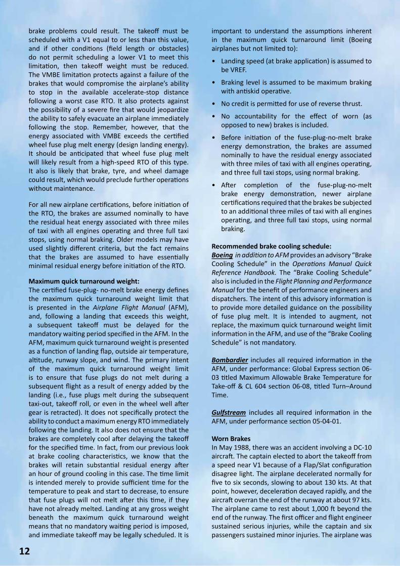
Worn BrakesIn May 1988, there was an accident involving a DC-10 aircraft. The captain elected to abort the takeoff from a speed near V1 because of a Flap/Slat configuration disagree light. The airplane decelerated normally for five to six seconds, slowing to about 130 kts. At that point, however, deceleration decayed rapidly, and the aircraft overran the end of the runway at about 97 kts. The airplane came to rest about 1,000 ft beyond the end of the runway. The first officer and flight engineer sustained serious injuries, while the captain and six passengers sustained minor injuries. The airplane was
13
By Stavros ArampatzisMaintenance Manager
declared a hull loss. The post-accident investigation revealed that the flaps and slats were in fact in a normal symmetric configuration and the Flap/Slat disagree warning was erroneously generated by an out-of-tolerance slat position sensor. Of much greater concern to the National Transportation Safety Board, however, was the discovery that 8 of the 10 brakes failed during the RTO. Two of the 10 brakes were almost new, and they operated normally during the RTO. All of the remaining brakes were at or near their wear limits before the RTO. The accident investigation revealed that the airplane’s maximum brake energy absorption capability was reduced, relative to the certified level, because of the advanced wear state of 8 of the 10 brakes, and that this reduction in brake energy absorption capability contributed to the brake failures during the stop.
One primary indicator of a brake’s ability to absorb energy is its mass. The brake’s “heat sink” mass, the combined mass of rotors and stators, may decrease by as much as 30% between a new brake assembly and a brake in the fully worn state. Up to 1988, airworthiness standards did not impose any requirement to demonstrate energy absorption or accelerate-stop capability with fully worn brakes.
There was a flurry of regulatory activity for several years following this accident investigation. The Federal Aviation Administration eventually issued
The American Airlines McDonnell Douglas DC-10-30 overran the runway during an aborted takeoff at Dallas. Investigation showed that the majority of the brakes were worn down below acceptable levels, resulting in the longer stopping distance.
airworthiness directives against all in-service transport category airplanes with maximum takeoff weights in excess of 75000 lb (34000 kg), reducing brake wear limits to account for the effect of worn brakes on energy absorption capability. While revised wear limits were viewed as an adequate answer for worn-brake accountability on in-service models, the FAA, JAA, and manufacturers worked together to re- write certification regulations and guidelines for new aircraft types to ensure that certified brake performance adequately addresses worn brake accountability from the start. All airplanes certified after the adoption of Amendment 25-92, effective 20 March 1998, and some airplanes certified before this time by special agreement, have included full worn-brake accountability in their certification. SummaryVarious operational situations have been identified where brake energy can be an important consideration. Thorough understanding of the issues, proper preflight inspection (PFI), and appropriate crew technique combine to minimize the risk of brake-related problems in these situations. It is important for all of us to recognize these situations and properly use all resources to ensure that operations are not only legal, but safe and efficient as well. The good news is that modern brake technology and improved testing and certification procedures provide an additional margin of safety not present in the past. References:• FAA/EASA PART 25 (SECTION 92) AIRPLANE
CERTIFICATION REQUIREMENTS • BOEING SERVICE LETTERS• GAINJET FLEET AIRPLANE FLIGHT MANUALS
14
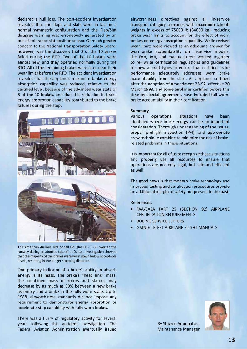
Industrial robots being used at a auto manufacturer factory.
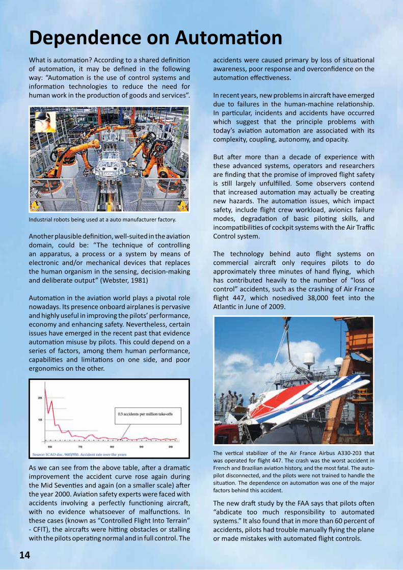
The vertical stabilizer of the Air France Airbus A330-203 that was operated for flight 447. The crash was the worst accident in French and Brazilian aviation history, and the most fatal. The auto-pilot disconnected, and the pilots were not trained to handle the situation. The dependence on automation was one of the major factors behind this accident.
Dependence on AutomationWhat is automation? According to a shared definition of automation, it may be defined in the following way: “Automation is the use of control systems and information technologies to reduce the need for human work in the production of goods and services”.
accidents were caused primary by loss of situational awareness, poor response and overconfidence on the automation effectiveness. In recent years, new problems in aircraft have emerged due to failures in the human-machine relationship. In particular, incidents and accidents have occurred which suggest that the principle problems with today’s aviation automation are associated with its complexity, coupling, autonomy, and opacity.
But after more than a decade of experience with these advanced systems, operators and researchers are finding that the promise of improved flight safety is still largely unfulfilled. Some observers contend that increased automation may actually be creating new hazards. The automation issues, which impact safety, include flight crew workload, avionics failure modes, degradation of basic piloting skills, and incompatibilities of cockpit systems with the Air Traffic Control system.
The technology behind auto flight systems on commercial aircraft only requires pilots to do approximately three minutes of hand flying, which has contributed heavily to the number of “loss of control” accidents, such as the crashing of Air France flight 447, which nosedived 38,000 feet into the Atlantic in June of 2009.
Another plausible definition, well-suited in the aviation domain, could be: “The technique of controlling an apparatus, a process or a system by means of electronic and/or mechanical devices that replaces the human organism in the sensing, decision-making and deliberate output” (Webster, 1981) Automation in the aviation world plays a pivotal role nowadays. Its presence onboard airplanes is pervasive and highly useful in improving the pilots’ performance, economy and enhancing safety. Nevertheless, certain issues have emerged in the recent past that evidence automation misuse by pilots. This could depend on a series of factors, among them human performance, capabilities and limitations on one side, and poor ergonomics on the other.
As we can see from the above table, after a dramatic improvement the accident curve rose again during the Mid Seventies and again (on a smaller scale) after the year 2000. Aviation safety experts were faced with accidents involving a perfectly functioning aircraft, with no evidence whatsoever of malfunctions. In these cases (known as “Controlled Flight Into Terrain” - CFIT), the aircrafts were hitting obstacles or stalling with the pilots operating normal and in full control. The
The new draft study by the FAA says that pilots often “abdicate too much responsibility to automated systems.” It also found that in more than 60 percent of accidents, pilots had trouble manually flying the plane or made mistakes with automated flight controls.
15
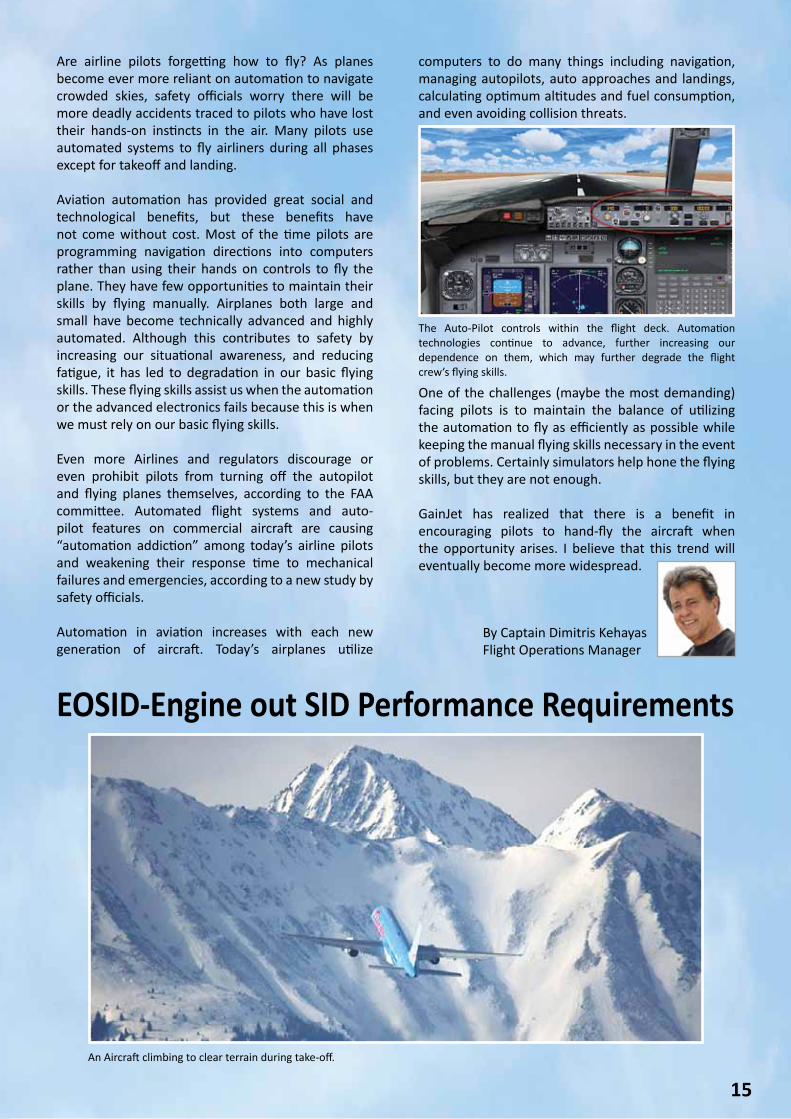
An Aircraft climbing to clear terrain during take-off.
The Auto-Pilot controls within the flight deck. Automation technologies continue to advance, further increasing our dependence on them, which may further degrade the flight crew’s flying skills.
By Captain Dimitris KehayasFlight Operations Manager
EOSID-Engine out SID Performance Requirements
Are airline pilots forgetting how to fly? As planes become ever more reliant on automation to navigate crowded skies, safety officials worry there will be more deadly accidents traced to pilots who have lost their hands-on instincts in the air. Many pilots use automated systems to fly airliners during all phases except for takeoff and landing.
Aviation automation has provided great social and technological benefits, but these benefits have not come without cost. Most of the time pilots are programming navigation directions into computers rather than using their hands on controls to fly the plane. They have few opportunities to maintain their skills by flying manually. Airplanes both large and small have become technically advanced and highly automated. Although this contributes to safety by increasing our situational awareness, and reducing fatigue, it has led to degradation in our basic flying skills. These flying skills assist us when the automation or the advanced electronics fails because this is when we must rely on our basic flying skills. Even more Airlines and regulators discourage or even prohibit pilots from turning off the autopilot and flying planes themselves, according to the FAA committee. Automated flight systems and auto-pilot features on commercial aircraft are causing “automation addiction” among today’s airline pilots and weakening their response time to mechanical failures and emergencies, according to a new study by safety officials.
Automation in aviation increases with each new generation of aircraft. Today’s airplanes utilize
computers to do many things including navigation, managing autopilots, auto approaches and landings, calculating optimum altitudes and fuel consumption, and even avoiding collision threats.
One of the challenges (maybe the most demanding) facing pilots is to maintain the balance of utilizing the automation to fly as efficiently as possible while keeping the manual flying skills necessary in the event of problems. Certainly simulators help hone the flying skills, but they are not enough.
GainJet has realized that there is a benefit in encouraging pilots to hand-fly the aircraft when the opportunity arises. I believe that this trend will eventually become more widespread.
16
ICAO Type A and Type C obstacle charts
Electronic aerodrome terrain and obstacle chart of the future
IntroductionAs the engine out SID procedure is part of your emergency takeoff briefing, the scope of this article is to present from a pilots’ perspective, the legal framework and how EOSID procedures are developed. We will also provide examples of commonly used engine out contingency procedures. Procedure names may differ as some of the common names used are Engine Out Contingency Procedures, Engine Out Escape Paths or EOSIDs - Engine Out SIDs. For IFR approved aircraft an EOSID must cover takeoffs in both VMC and IMC. During this article, engine out takeoff guidance will be referred to as an EOSID. The most common procedure to maximize takeoff weight when significant obstacles are present along the normal departure route is to use an EOSID in the event of an engine failure on take-off. In order for an operator to determine that a departure maintains the necessary obstacle clearance with an engine failure, the operator should consider that an engine failure may occur at any point on the departure flight path.
If the EOSID routing is different from a SID, the obstacles along this track are used to determine the maximum allowable take-off weight for that particular runway. In the event that the aircraft cannot return to and land at the departure airport, the takeoff flight path should follow a suitable route to the planned destination or takeoff alternate. Analysis of an engine failure after takeoff may also require the use of performance data in addition to that provided in the Aircraft Flight Manual. It is recognized that many AFM’s generally contain only the engine out performance for loss of an engine at V1 on takeoff.
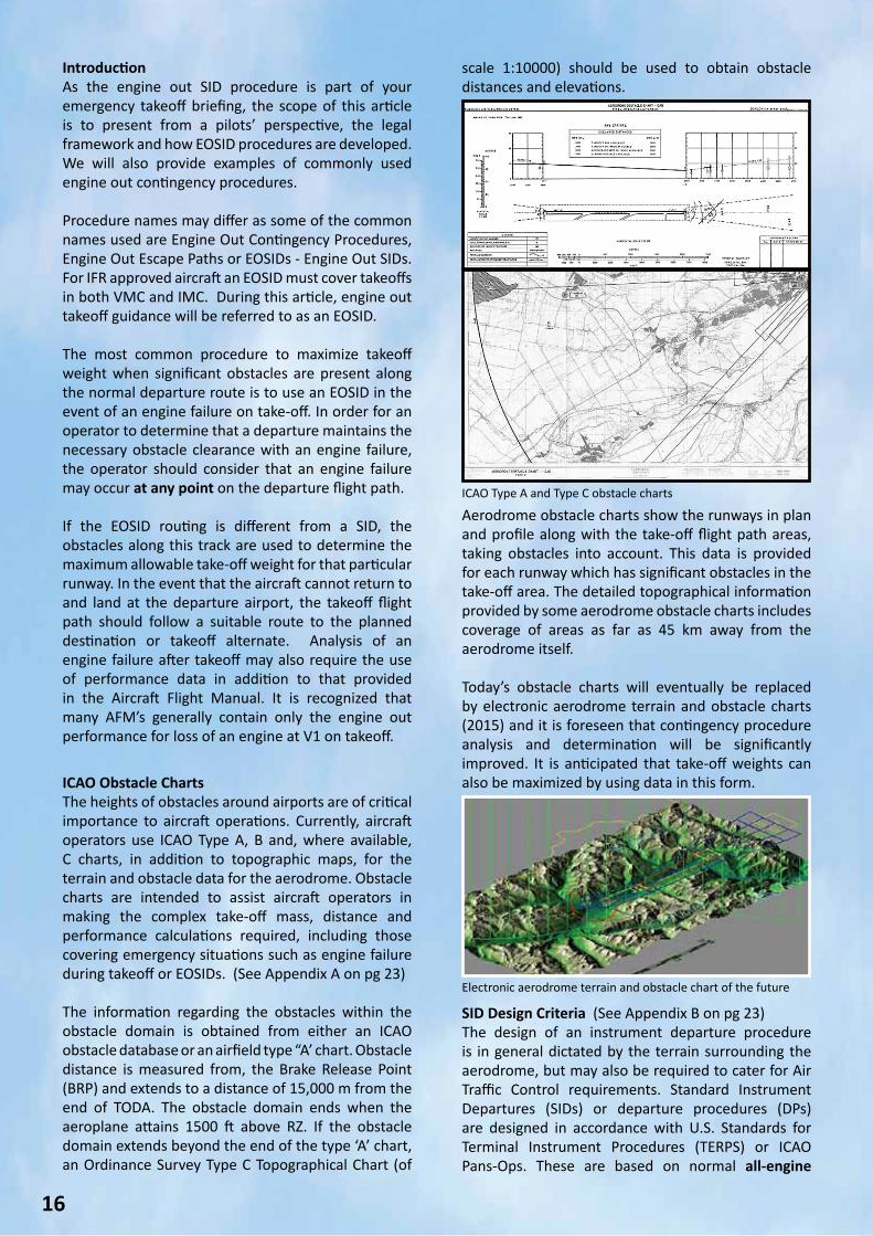
ICAO Obstacle ChartsThe heights of obstacles around airports are of critical importance to aircraft operations. Currently, aircraft operators use ICAO Type A, B and, where available, C charts, in addition to topographic maps, for the terrain and obstacle data for the aerodrome. Obstacle charts are intended to assist aircraft operators in making the complex take-off mass, distance and performance calculations required, including those covering emergency situations such as engine failure during takeoff or EOSIDs. (See Appendix A on pg 23) The information regarding the obstacles within the obstacle domain is obtained from either an ICAO obstacle database or an airfield type “A’ chart. Obstacle distance is measured from, the Brake Release Point (BRP) and extends to a distance of 15,000 m from the end of TODA. The obstacle domain ends when the aeroplane attains 1500 ft above RZ. If the obstacle domain extends beyond the end of the type ‘A’ chart, an Ordinance Survey Type C Topographical Chart (of
scale 1:10000) should be used to obtain obstacle distances and elevations.
Aerodrome obstacle charts show the runways in plan and profile along with the take-off flight path areas, taking obstacles into account. This data is provided for each runway which has significant obstacles in the take-off area. The detailed topographical information provided by some aerodrome obstacle charts includes coverage of areas as far as 45 km away from the aerodrome itself.
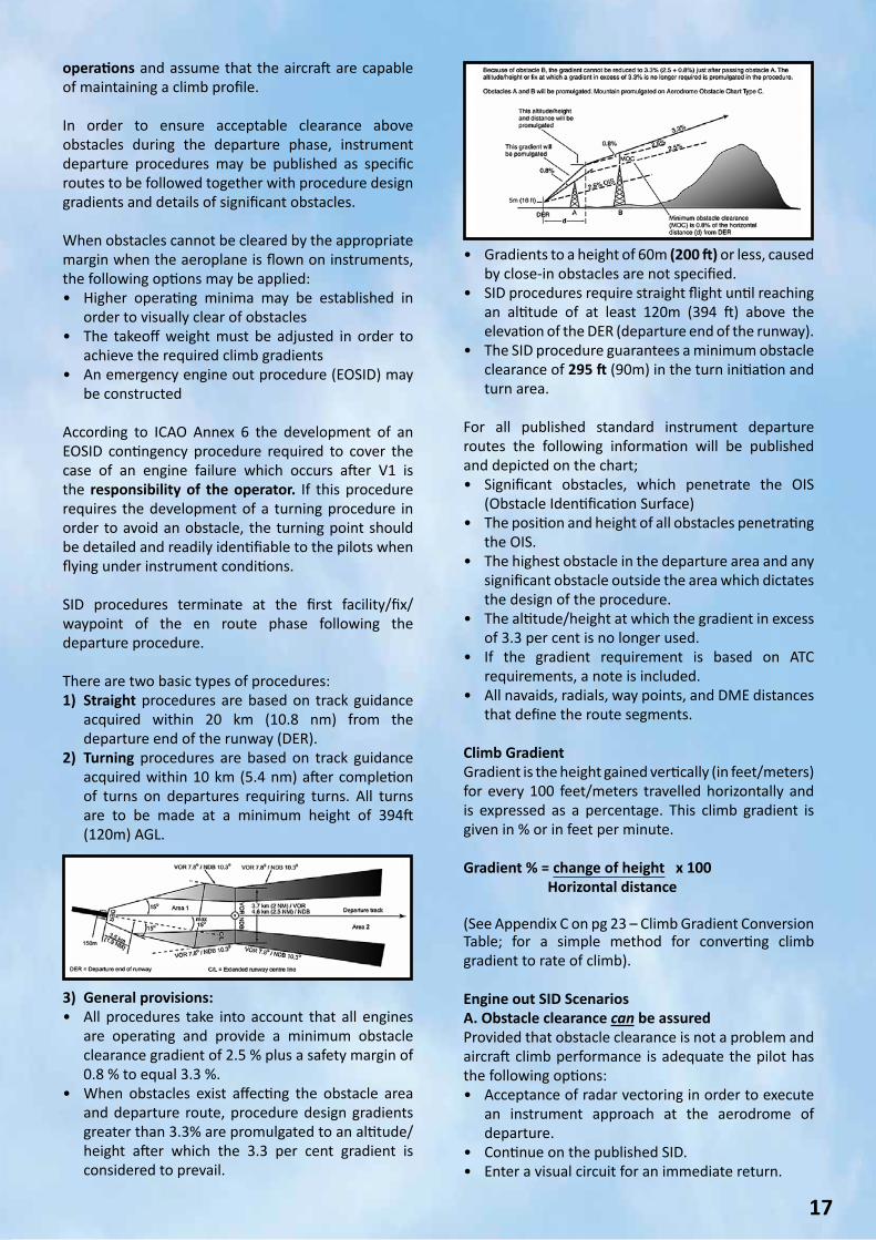
Today’s obstacle charts will eventually be replaced by electronic aerodrome terrain and obstacle charts (2015) and it is foreseen that contingency procedure analysis and determination will be significantly improved. It is anticipated that take-off weights can also be maximized by using data in this form.
SID Design Criteria (See Appendix B on pg 23)The design of an instrument departure procedure is in general dictated by the terrain surrounding the aerodrome, but may also be required to cater for Air Traffic Control requirements. Standard Instrument Departures (SIDs) or departure procedures (DPs) are designed in accordance with U.S. Standards for Terminal Instrument Procedures (TERPS) or ICAO Pans-Ops. These are based on normal all-engine
17
operations and assume that the aircraft are capable of maintaining a climb profile. In order to ensure acceptable clearance above obstacles during the departure phase, instrument departure procedures may be published as specific routes to be followed together with procedure design gradients and details of significant obstacles. When obstacles cannot be cleared by the appropriate margin when the aeroplane is flown on instruments, the following options may be applied:• Higher operating minima may be established in
order to visually clear of obstacles• The takeoff weight must be adjusted in order to
achieve the required climb gradients• An emergency engine out procedure (EOSID) may
be constructed According to ICAO Annex 6 the development of an EOSID contingency procedure required to cover the case of an engine failure which occurs after V1 is the responsibility of the operator. If this procedure requires the development of a turning procedure in order to avoid an obstacle, the turning point should be detailed and readily identifiable to the pilots when flying under instrument conditions. SID procedures terminate at the first facility/fix/waypoint of the en route phase following the departure procedure. There are two basic types of procedures:1) Straight procedures are based on track guidance
acquired within 20 km (10.8 nm) from the departure end of the runway (DER).
2) Turning procedures are based on track guidance acquired within 10 km (5.4 nm) after completion of turns on departures requiring turns. All turns are to be made at a minimum height of 394ft (120m) AGL.
• Gradients to a height of 60m (200 ft) or less, caused by close-in obstacles are not specified.
• SID procedures require straight flight until reaching an altitude of at least 120m (394 ft) above the elevation of the DER (departure end of the runway).
• The SID procedure guarantees a minimum obstacle clearance of 295 ft (90m) in the turn initiation and turn area.
For all published standard instrument departure routes the following information will be published and depicted on the chart;• Significant obstacles, which penetrate the OIS
(Obstacle Identification Surface)• The position and height of all obstacles penetrating
the OIS.• The highest obstacle in the departure area and any
significant obstacle outside the area which dictates the design of the procedure.
• The altitude/height at which the gradient in excess of 3.3 per cent is no longer used.
• If the gradient requirement is based on ATC requirements, a note is included.
• All navaids, radials, way points, and DME distances that define the route segments.
Climb GradientGradient is the height gained vertically (in feet/meters) for every 100 feet/meters travelled horizontally and is expressed as a percentage. This climb gradient is given in % or in feet per minute.
Gradient % = change of height x 100 Horizontal distance
(See Appendix C on pg 23 – Climb Gradient Conversion Table; for a simple method for converting climb gradient to rate of climb). Engine out SID ScenariosA. Obstacle clearance can be assuredProvided that obstacle clearance is not a problem and aircraft climb performance is adequate the pilot has the following options:• Acceptance of radar vectoring in order to execute
an instrument approach at the aerodrome of departure.
• Continue on the published SID.• Enter a visual circuit for an immediate return.
3) General provisions:• All procedures take into account that all engines
are operating and provide a minimum obstacle clearance gradient of 2.5 % plus a safety margin of 0.8 % to equal 3.3 %.
• When obstacles exist affecting the obstacle area and departure route, procedure design gradients greater than 3.3% are promulgated to an altitude/height after which the 3.3 per cent gradient is considered to prevail.
18
B. Obstacle clearance cannot be assuredIf obstacle clearance cannot be ensured, the safe continuation of the flight can only be guaranteed through compliance with the Engine Out SID procedure for that specific runway. These procedures can be depicted on a customized chart, the takeoff analysis software or the FMS database. Example A: Standard Procedure
• Climb straight ahead at V2 speed until the level-off height for acceleration is reached. In case of restrictive distant obstacle conditions, an individual level-off height has to be specified for the runway concerned.
• Level off and retract the flaps while turning with a 15° bank, proceeding to the navaid specified on the takeoff analysis chart for the takeoff runway. If not otherwise stated, make the shortest turn to the navaid. If a 180° turn is required, the direction of turn is optional except if “LT to” or “RT to” is prescribed on the chart.
• After flap retraction, which may be prior to or after reaching the navaid, continue climb to desired altitude for further action (MSA, MHA) using 25 degrees of bank.
• If required, enter the holding pattern using standard entry and holding procedures. Obstacle clearance has to be assured within an area of 5 NM around the holding pattern.
Example B: Tailored RTOW Chart EOSID Procedure
References: • Aircraft Performance Theory – P.J. Swatton• ICAO Document 8168• Jeppesen Airway Manual• Lufthansa Performance Handbook• ICAO Aeronautical Chart Publication• ICAO Annex 6• EU- OPS 1• CAP 235-4(0)
By Captain Antonios NikolaouAccountable Manager & G550/G450 Captain
19
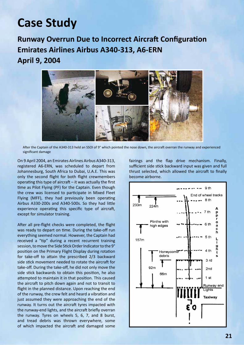
Case StudyTailstrike Due to Incorrect Aircraft ConfigurationEmirates Airlines Airbus A340-541, A6-ERGMarch 20, 2009
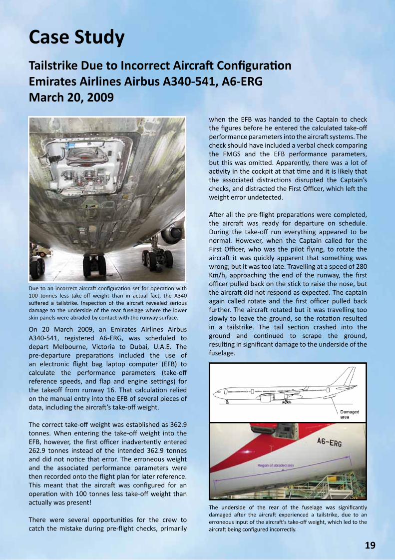
Due to an incorrect aircraft configuration set for operation with 100 tonnes less take-off weight than in actual fact, the A340 suffered a tailstrike. Inspection of the aircraft revealed serious damage to the underside of the rear fuselage where the lower skin panels were abraded by contact with the runway surface.
The underside of the rear of the fuselage was significantly damaged after the aircraft experienced a tailstrike, due to an erroneous input of the aircraft’s take-off weight, which led to the aircraft being configured incorrectly.
On 20 March 2009, an Emirates Airlines Airbus A340-541, registered A6-ERG, was scheduled to depart Melbourne, Victoria to Dubai, U.A.E. The pre-departure preparations included the use of an electronic flight bag laptop computer (EFB) to calculate the performance parameters (take-off reference speeds, and flap and engine settings) for the takeoff from runway 16. That calculation relied on the manual entry into the EFB of several pieces of data, including the aircraft’s take-off weight. The correct take-off weight was established as 362.9 tonnes. When entering the take-off weight into the EFB, however, the first officer inadvertently entered 262.9 tonnes instead of the intended 362.9 tonnes and did not notice that error. The erroneous weight and the associated performance parameters were then recorded onto the flight plan for later reference. This meant that the aircraft was configured for an operation with 100 tonnes less take-off weight than actually was present! There were several opportunities for the crew to catch the mistake during pre-flight checks, primarily
when the EFB was handed to the Captain to check the figures before he entered the calculated take-off performance parameters into the aircraft systems. The check should have included a verbal check comparing the FMGS and the EFB performance parameters, but this was omitted. Apparently, there was a lot of activity in the cockpit at that time and it is likely that the associated distractions disrupted the Captain’s checks, and distracted the First Officer, which left the weight error undetected.
After all the pre-flight preparations were completed, the aircraft was ready for departure on schedule. During the take-off run everything appeared to be normal. However, when the Captain called for the First Officer, who was the pilot flying, to rotate the aircraft it was quickly apparent that something was wrong; but it was too late. Travelling at a speed of 280 Km/h, approaching the end of the runway, the first officer pulled back on the stick to raise the nose, but the aircraft did not respond as expected. The captain again called rotate and the first officer pulled back further. The aircraft rotated but it was travelling too slowly to leave the ground, so the rotation resulted in a tailstrike. The tail section crashed into the ground and continued to scrape the ground, resulting in significant damage to the underside of the fuselage.
20
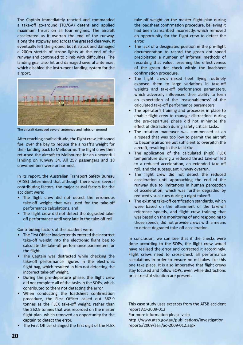
The Captain immediately reacted and commanded a take-off go-around (TO/GA) detent and applied maximum thrust on all four engines. The aircraft accelerated as it overran the end of the runway, along the stopway and across the grassed clearway. It eventually left the ground, but it struck and damaged a 200m stretch of strobe lights at the end of the runway and continued to climb with difficulties. The landing gear also hit and damaged several antennae, which disabled the instrument landing system for the airport.
take-off weight on the master flight plan during the loadsheet confirmation procedure, believing it had been transcribed incorrectly, which removed an opportunity for the flight crew to detect the error.
• The lack of a designated position in the pre-flight documentation to record the green dot speed precipitated a number of informal methods of recording that value, lessening the effectiveness of the green dot check within the loadsheet confirmation procedure.
• The flight crew’s mixed fleet flying routinely exposed them to large variations in take-off weights and take-off performance parameters, which adversely influenced their ability to form an expectation of the ‘reasonableness’ of the calculated take-off performance parameters.
• The operator’s training and processes in place to enable flight crew to manage distractions during the pre-departure phase did not minimize the effect of distraction during safety critical tasks.
• The rotation maneuver was commenced at an airspeed that was too low to permit the aircraft to become airborne but sufficient to overpitch the aircraft, resulting in the tailstrike.
• The application of the calculated (high) FLEX temperature during a reduced thrust take-off led to a reduced acceleration, an extended take-off roll, and the subsequent runway overrun.
• The flight crew did not detect the reduced acceleration until approaching the end of the runway due to limitations in human perception of acceleration, which was further degraded by reduced visual cues during a night takeoff.
• The existing take-off certification standards, which were based on the attainment of the take-off reference speeds, and flight crew training that was based on the monitoring of and responding to those speeds, did not provide crews with a means to detect degraded take-off acceleration.
In conclusion, we can see that if the checks were done according to the SOPs, the flight crew would have realized the error and corrected it accordingly. Flight crews need to cross-check all performance calculations in order to ensure no mistakes like this one take place. It is also imperative that flight crews stay focused and follow SOPs, even while distractions or a stressful situation are present.
After reaching a safe altitude, the flight crew jettisoned fuel over the bay to reduce the aircraft’s weight for their landing back to Melbourne. The flight crew then returned the aircraft to Melbourne for an uneventful landing on runway 34. All 257 passengers and 18 crewmembers were unharmed.
In its report, the Australian Transport Safety Bureau (ATSB) determined that although there were several contributing factors, the major causal factors for the accident were:• The flight crew did not detect the erroneous
take-off weight that was used for the take-off performance calculations, and
• The flight crew did not detect the degraded take-off performance until very late in the take-off roll.
Contributing factors of the accident were:• The First Officer inadvertently entered the incorrect
take-off weight into the electronic flight bag to calculate the take-off performance parameters for the flight.
• The Captain was distracted while checking the take-off performance figures in the electronic flight bag, which resulted in him not detecting the incorrect take-off weight.
• During the pre-departure phase, the flight crew did not complete all of the tasks in the SOPs, which contributed to them not detecting the error.
• When conducting the loadsheet confirmation procedure, the First Officer called out 362.9 tonnes as the FLEX take-off weight, rather than the 262.9 tonnes that was recorded on the master flight plan, which removed an opportunity for the captain to detect the error.
• The First Officer changed the first digit of the FLEX
The aircraft damaged several antennae and lights on ground
This case study uses excerpts from the ATSB accident report AO-2009-012For more information please visit:http://www.atsb.gov.au/publications/investigation_reports/2009/aair/ao-2009-012.aspx
21
Case StudyRunway Overrun Due to Incorrect Aircraft ConfigurationEmirates Airlines Airbus A340-313, A6-ERNApril 9, 2004
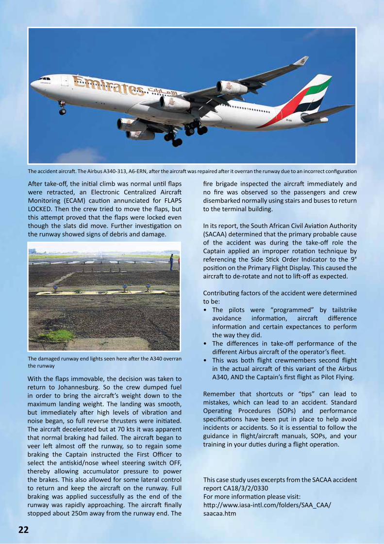
On 9 April 2004, an Emirates Airlines Airbus A340-313, registered A6-ERN, was scheduled to depart from Johannesburg, South Africa to Dubai, U.A.E. This was only the second flight for both flight crewmembers operating this type of aircraft – it was actually the first time as Pilot Flying (PF) for the Captain. Even though the crew was licensed to participate in Mixed Fleet Flying (MFF), they had previously been operating Airbus A330-200s and A340-500s. So they had little experience operating this specific type of aircraft, except for simulator training. After all pre-flight checks were completed, the flight was ready to depart on time. During the take-off run everything seemed normal. However, the Captain had received a “tip” during a recent recurrent training session, to move the Side Stick Order Indicator to the 9° position on the Primary Flight Display during rotation for take-off to attain the prescribed 2/3 backward side stick movement needed to rotate the aircraft for take-off. During the take-off, he did not only move the side stick backwards to obtain this position, he also attempted to maintain it in that position. This caused the aircraft to pitch down again and not to transit to flight in the planned distance. Upon reaching the end of the runway, the crew felt and heard a vibration and just assumed they were approaching the end of the runway. It turns out the aircraft tyres impacted with the runway-end lights, and the aircraft briefly overran the runway. Tyres on wheels 5, 6, 7, and 8 burst, and tread debris was thrown everywhere, some of which impacted the aircraft and damaged some
fairings and the flap drive mechanism. Finally, sufficient side stick backward input was given and full thrust selected, which allowed the aircraft to finally become airborne.
After the Captain of the A340-313 held an SSOI of 9° which pointed the nose down, the aircraft overran the runway and experiencedsignificant damage
22
After take-off, the initial climb was normal until flaps were retracted, an Electronic Centralized Aircraft Monitoring (ECAM) caution annunciated for FLAPS LOCKED. Then the crew tried to move the flaps, but this attempt proved that the flaps were locked even though the slats did move. Further investigation on the runway showed signs of debris and damage.
fire brigade inspected the aircraft immediately and no fire was observed so the passengers and crew disembarked normally using stairs and buses to return to the terminal building. In its report, the South African Civil Aviation Authority (SACAA) determined that the primary probable cause of the accident was during the take-off role the Captain applied an improper rotation technique by referencing the Side Stick Order Indicator to the 9° position on the Primary Flight Display. This caused the aircraft to de-rotate and not to lift-off as expected. Contributing factors of the accident were determined to be:• The pilots were “programmed” by tailstrike
avoidance information, aircraft difference information and certain expectances to perform the way they did.
• The differences in take-off performance of the different Airbus aircraft of the operator’s fleet.
• This was both flight crewmembers second flight in the actual aircraft of this variant of the Airbus A340, AND the Captain’s first flight as Pilot Flying.
Remember that shortcuts or “tips” can lead to mistakes, which can lead to an accident. Standard Operating Procedures (SOPs) and performance specifications have been put in place to help avoid incidents or accidents. So it is essential to follow the guidance in flight/aircraft manuals, SOPs, and your training in your duties during a flight operation.
This case study uses excerpts from the SACAA accident report CA18/3/2/0330For more information please visit:http://www.iasa-intl.com/folders/SAA_CAA/saacaa.htm
The accident aircraft. The Airbus A340-313, A6-ERN, after the aircraft was repaired after it overran the runway due to an incorrect configuration
The damaged runway end lights seen here after the A340 overran the runway
With the flaps immovable, the decision was taken to return to Johannesburg. So the crew dumped fuel in order to bring the aircraft’s weight down to the maximum landing weight. The landing was smooth, but immediately after high levels of vibration and noise began, so full reverse thrusters were initiated. The aircraft decelerated but at 70 kts it was apparent that normal braking had failed. The aircraft began to veer left almost off the runway, so to regain some braking the Captain instructed the First Officer to select the antiskid/nose wheel steering switch OFF, thereby allowing accumulator pressure to power the brakes. This also allowed for some lateral control to return and keep the aircraft on the runway. Full braking was applied successfully as the end of the runway was rapidly approaching. The aircraft finally stopped about 250m away from the runway end. The
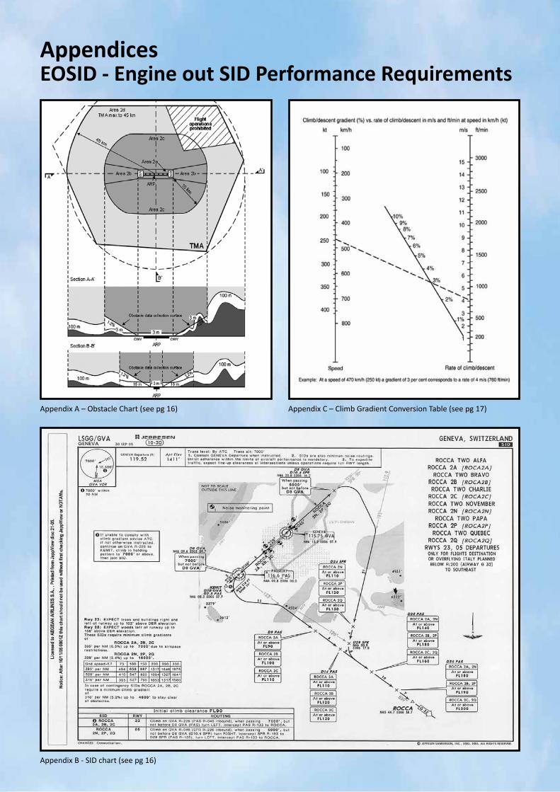
AppendicesEOSID - Engine out SID Performance Requirements
Appendix A – Obstacle Chart (see pg 16) Appendix C – Climb Gradient Conversion Table (see pg 17)
Appendix B - SID chart (see pg 16)

For any questions or safety/security concerns please contact:GainJet Aviation S.APhone: +30 210 9636101
Or visit www.gainjet.com
Capt. Vangelis LykoudisFlight Safety Officer (FSO)Email: [email protected]
Mr. Vassilis ApostolouCompany Security OfficerEmail: [email protected]


![Flight! Magazin - Flight! Februar 2012 [CLASSICS]](https://img.pdfslide.us/doc/110x75/568ca77e1a28ab186d9592a3/flight-magazin-flight-februar-2012-classics.jpg)
![Flight! Magazin - Flight! Januar 2012 [CLASSICS]](https://img.pdfslide.us/doc/110x75/568ca7881a28ab186d95be91/flight-magazin-flight-januar-2012-classics.jpg)