Embed Size (px)
Citation preview

Construction Standards for Potable Water, Wastewater, Reclaimed Water, Lift Stations, & Jack and Bore
Page: 1
Gainesville Regional Utilities
Construction Standards
for
Potable Water Wastewater
Reclaimed Water Lift Stations
and Jack and Bore
Construction Standards for Potable Water, Wastewater, Reclaimed Water, Lift Stations, & Jack and Bore
Page: 2
TABLE OF CONTENTS
Section I Gainesville Regional Utilities Water Construction Standards……….……………….……5
1.0 Scope……………………………………………………………………………………………6 2.0 Inspection and Disposition of Materials………………………………………………………..6
3.0 Protection of Property and Obstructions……………………………………………………..6 4.0 Trench Preparation……………………………………………………………………………..7 5.0 Handling and Cutting Pipe……………………………………………………………………..7 6.0 Pipeline Construction…………………………………………………………………………...8 7.0 Services………………………………………………………………………………………….10 8.0 Paving, Curb, Gutter, and Walkway Work……………………………………………………10
9.0 Testing………………………………………………………………………………………….11
10.0 Disinfection……………………………………………………………………………………12
11.0 Final Acceptance…………………………………………………………………………….13
Section II Gainesville Regional Utilities Wastewater Construction Details…..….…....…………..14
1.0 Scope…………………………………………………………………………………………….15 2.0 Inspection and Disposition of Materials………………………………………………………15
3.0 Protection of Property and Obstructions……………………………………………………..15
4.0 Trench Preparation………………………..……………………………………………………16
5.0 Handling and Cutting Pipe……………………………………………………..………………17
6.0 Force Main…………...………………………………………………………………………….17
7.0 Gravity Collection System……………………………………………………………………..19 8.0 Manholes………………………………………………………………………………………...21
9.0 Lift Stations………………………………………………………………………………………22
10.0 Paving, Curb, Gutter, and Walkway Work………………………………………………….23

Construction Standards for Potable Water, Wastewater, Reclaimed Water, Lift Stations, & Jack and Bore
Page: 3
11.0 Testing………………………………………………………………………………………….23
12.0 Final Acceptance………………………………………………………………………………24
Section III Gainesville Regional Utilities Reclaimed Water Construction Standards…………26
1.0 Scope…………………………………………………………………………………………….27
2.0 Inspection and Disposition of Materials………………………………………………………27
3.0 Protection of Property and Obstructions……………………………………………………..27 4.0 Trench Preparation……………………………………………………………………………..28
5.0 Handling and Cutting Pipe……………………………………………………………………..29 6.0 Pipeline Construction…………………………………………………………………………..29
7.0 Paving, Curb, Gutter, and Walkway Work……………………………………………………31
8.0 Testing…………………………………………………………………………………………...32
9.0 Identification……………………………………………………………………………………..33
10.0 Final Acceptance………………………………………………………………………………33 11.0 Backflow Prevention Requirements…………………………………………………………34
12.0 Reclaimed Water Construction Standard Drawings………………………………………34
Section IV Gainesville Regional Utilities Lift Station Construction Standards…………………35
1.0 Scope…………………………………………………………………………………………….36 2.0 Developer/Engineer Responsibility…………………………………………………………...36 3.0 Pumps……………………………………………………………………………………………37 4.0 Electric Controls………………………………………………………………………………...38 5.0 Access Frame and Cover……………………………………………………………………...39 6.0 Quality Assurance………………………………………………………………………………39 7.0 Warranty………………………..………………………………………………………………..39
Construction Standards for Potable Water, Wastewater, Reclaimed Water, Lift Stations, & Jack and Bore
Page: 4
8.0 Manufacturer’s Shop Drawings………………………………………………………………..40 9.0 Evaluation of Materials…………………………………………………………………………41 10.0 Inspection………………………………………………………………………………………42 11.0 Start-Up & Final Acceptance…………………………………………………………………42
Section V Gainesville Regional Utilities Jack and Bore Construction Standards…………44
1.0 Scope…………………………………………………………………………………………….45
2.0 Inspection and Disposition of Materials………………………………………………………45
3.0 Protection of Property and Obstructions……………………………………………………..45 4.0 Materials, Services, Facilities..………………………………………………………………..45 5.0 Encasement Pipe……………………………………………………………………………….46 6.0 Boring and Jacking Method……………………………………………………………………48
7.0 Completion and Clean-Up……………………………………………………………………..48 8.0 Paving, Curb, Gutter & Walkway Work……………………………………………………….49 9.0 Casing Spacers…………………………………………………………………………………49

Construction Standards for Potable Water, Wastewater, Reclaimed Water, Lift Stations, & Jack and Bore
Page: 5
Section I
Gainesville Regional Utilities
Water Construction Standards
Construction Standards for Potable Water, Wastewater, Reclaimed Water, Lift Stations, & Jack and Bore
Page: 6
1.0 SCOPE
1.1 The purpose and intent of these Standards and the accompanying Construction Details is
to provide for the furnishing and installation of a WATER TRANSMISSION AND
DISTRIBUTION SYSTEM.
1.2 Engineers, Developers, Contractors, Inspectors, and others concerned with water construction shall perform all work in accordance with these requirements. Any modifications to these standards shall require the Water/Wastewater Engineering Department’s approval.
1.3 All Water Main Construction methods and materials, including piping, valves, fire hydrants
etc., and associated appurtenances shall conform to current GRU and AWWA standards.
2.0 INSPECTION AND DISPOSITION OF MATERIALS
2.1 Material delivered to the job site shall be inspected. Materials found during inspection or
during the progress of the work to have cracks, flaws, surface abrasions, cracked linings, or
other defects shall be rejected and removed from the job site without delay. All materials
delivered to the job site shall be in accordance with the Approved Water Materials Manual.
2.2 Pipe delivered to the job site shall be unloaded opposite or near the place where it is to be
installed. Materials shall be loaded and unloaded by loader, lifting hoists, or skidding so as to
avoid shock and prevent damage. Materials unloaded by skidways shall not be skipped or
rolled against materials already on the ground
3.0 PROTECTION OF PROPERTY AND OBSTRUCTIONS
3.1 Temporary supports and/or adequate protection shall be installed and maintained on all
underground and surface structures encountered in the progress of the work. Structures that
have been disturbed shall be restored upon completion of the work.
3.2 Underground Utilities shall be notified and utility locates performed (call 811) prior to
beginning construction. Any known obstructions shall be shown on the Drawings. The
utmost caution shall be taken in all operations to avoid damage to existing obstructions (for
example, pipes, cables, conduit, utility poles, structures, etc.) whether or not shown on the
Drawings.
3.3 Existing utilities shall be kept in operation by temporary lines, temporary pumps, or other
means provided for continuous operation of utilities. All this work shall be installed,
maintained, operated, and removed upon completion of the job.
Construction Standards for Potable Water, Wastewater, Reclaimed Water, Lift Stations, & Jack and Bore
Page: 7
4.0 TRENCH PREPARATION
4.1 The trench shall be opened so that the pipe can be installed to the alignment and depth required. The trench shall be excavated only so far in advance of pipe installation as to insure proper installation in accordance with Gainesville Regional Utilities Construction Standards.
4.2 The trench shall be excavated to the depth required so as to provide a uniform and continuous bearing support for the pipe on undisturbed ground. Bell holes shall be provided at each joint to permit jointing to be made properly and inspected.
4.3 Excavated material shall be piled in such a manner that it will not endanger the work,
obstruct natural water courses, sidewalks, or driveways. Fire hydrants under pressure, valve pit covers, valve boxes, fire and police call boxes, or other utility controls shall be left unobstructed and accessible at all times. Gutters shall be kept clear or other satisfactory provisions made for street drainage. All surface materials which are suitable for reuse in restoring the surface shall be kept separate from any unacceptable excavated material.
4.4 Sheeting and bracing which have been ordered left in place must be removed to a depth of
four (4) feet below the established grade. Trench bracing, except that which must be left in place, may be removed after the backfilling has been completed or has been brought up to such an elevation as to permit its safe removal. The use of a trench box may be allowed unless sheeting and bracing is required by the Engineer or OSHA.
4.5 Water shall not be allowed in the trench at any time. An adequate supply of well points, headers, and pumps, all in first class operating condition, may be used to remove the water. The use of gravel and pumps shall also be an acceptable means of removing the water. The trench shall be excavated no more than the available pumping facilities are capable of handling. The discharge from pumps shall be routed to natural drainage channels or emptied into drains or storm sewers, or as required by EPA, FDEP, Water Management District, or other agencies.
5.0 HANDLING AND CUTTING PIPE
5.1 Every care shall be taken in handling and laying pipe and fittings to avoid damaging the pipe, scratching or marring machined surfaces, and abrasion of the pipe coating.
5.2 Lined pipe and fittings must be handled only from the outside of the pipe and fittings. No forks, chains, straps, hooks, etc. shall be placed inside the pipe or fittings for lifting, positioning, or laying. If damaged, the material shall be repaired in accordance with the liner manufacturer’s recommendations and to GRU’s satisfaction.
5.3 Except as otherwise approved, all cutting shall be done with a power driven cut off saw. All
cut ends shall be examined for possible cracks caused by cutting.

Construction Standards for Potable Water, Wastewater, Reclaimed Water, Lift Stations, & Jack and Bore
Page: 8
6.0 PIPELINE CONSTRUCTION
6.1 Gainesville Regional Utilities Water and Wastewater Engineering Department shall be
notified forty-eight (48) hours prior to beginning construction. Inspectors may require a visual inspection on all piping systems installed without notification of Gainesville Regional Utilities.
6.2 Water mains shall be constructed as indicated on the drawings. Fittings and valves shall be mechanical joint. Materials installed shall be in accordance with the materials indicated in the Gainesville Regional Utilities Approved Materials Manual.
6.3 Any material items not included in the Approved Materials Manual shall not be installed.
Specialty items shall be approved by Gainesville Regional Utilities prior to installation.
6.4 The bottom of the trench shall not be excavated below the specified grade. If undercutting
occurs, the bottom of the trench shall be brought up to the original grade with approved material, thoroughly compacted, as directed by Gainesville Regional Utilities.
6.5 Before placing pipe into the trench, the outside of the spigot and the inside of the bell shall
be wiped clean and dry, free from oil and grease. Every precaution shall be taken to prevent foreign material from entering the pipe. During layout operation, no debris, tools, clothing, or other material shall be placed into the pipe.
6.6 After placing a length of pipe in the trench, the spigot end shall be centered in the bell, the
pipe pushed home (to the manufacture’s mark for PVC pipe), brought to correct alignment, and covered with an approved backfill material. Chlorine tablets shall be placed inside of the pipe near each bell. If plastic pipe is installed, a blue insulated, solid conductor, 10 gauge copper wire shall lie on top of the pipe and be taped every ten feet for location purposes. Each fire hydrant shall have one wrap of the wire around the barrel located at final grade and connected to the wire on the water main.
6.7 When pipe laying is not in progress, the open ends of pipe shall be closed by a water tight
plug or other approved means. This provision shall apply during the noon hour as well as overnight. If water is in the trench, the seal shall remain in place until the trench is pumped completely dry.
6.8 Backfilling material shall be free from cinders, ashes, refuse, vegetable or organic material,
boulders, rocks, stones, or other material which is considered unsuitable. When backfill material is not specified on the Drawings, backfilling with the excavated material may be acceptable provided that such material is suitable for backfilling.
6.9 Placement of the embedment materials is the most important part of pipe laying. The five
groups of embedment materials listed in the Construction Details include a number of processed materials plus the soil types defined according to the United Soil Classification System (USCS) in ASTM D-2487, Standard Method of Classification of Soils for Engineering Purposes.
Construction Standards for Potable Water, Wastewater, Reclaimed Water, Lift Stations, & Jack and Bore
Page: 9
6.10 Special bedding may be required in poor soil conditions. After placement of the pipe the soil
shall be consolidated to the spring line of the pipe by hand tamping the soil in place. From
the spring line of the pipe to two (2) feet above the pipe the soil shall be carefully backfilled
in 6” lifts and the soil consolidated with a hand operated tamping machine (or as required by
City, County, or State inspectors). After placement and compaction of the embedment
material, the balance of the backfill material may be machine placed or as required by the
Inspector and shall not contain any rocks or debris. All work under pavement shall be
conducted in accordance with any state, county, or local requirements.
6.11 Mechanical joints shall be made up in strict accordance with the manufacturer's
specifications. Gaskets shall be lubricated and evenly seated, the gland placed in position,
with the bolts hand tightened before final tightening by wrenches. Tighten T-bolts to the
recommended torque. Do not over-torque to avoid crushing the gasket. Maintain the same
overall gap between the gland and the MJ fitting face by tightening the T-bolts in a uniform
criss-cross pattern (12 o’clock, 6 o’clock, 3 o’clock, 9 o’clock, etc.) until proper torque is
achieved. Using a torque wrench is highly recommended. Wait 10 minutes to allow gasket to
relax, and retighten bolts to proper torque.
6.12 Push-on joints shall be made up in strict accordance with the manufacturer's specifications.
The bell shall be carefully cleaned before the gasket is inserted. The spigot shall be cleaned
while suspended above the trench. The joint shall then be lubricated with a non-toxic
lubricant and the pipe pushed home (note: on PVC pipe, this is indicated by the
manufacturer’s mark).
6.13 Maximum joint deflection of ductile iron and PVC pipe shall be limited to 80% of the pipe
manufacturer’s recommendation. PVC pipe may be bent to a radius 20% greater than the
manufacturer’s recommendation. If a bend is needed to facilitate construction, but has not
been included on the design drawings, one must be added as directed by the Engineer.
6.14 Valves and fittings shall be set and joined to the pipe in the proper location as specified in
the Drawings. A valve box shall be provided for every valve. The valve box shall not transmit
shock or stress to the valve and shall be centered and plumb over the operating nut of the
valve, with the box cover flush with the final grade or as may be specified in the Drawings.
6.15 NOTE: Before backfilling is complete, Contractor shall coordinate with GRU Inspector for a
visual inspection of all mechanical joint restraints/fittings and for proper backfill (see
Appendix B – Contractor Responsibilities).
Construction Standards for Potable Water, Wastewater, Reclaimed Water, Lift Stations, & Jack and Bore
Page: 10
6.16 Fire hydrants shall be located as shown on the Drawings and in a manner to provide
complete accessibility, and also in such a manner that the possibility of damage from
vehicles or injury to pedestrians will be minimized. All hydrants will stand plumb with the
proper nozzle facing the curb and the bury line of the hydrant at the final grade (+2”, -6”).
The barrel of the fire hydrant shall be set so that no portion of pumper nozzle or hose nozzle
will be less than 12 inches from the curb, walkway, or bike path and no more than 20 feet
from the face of the curb. All fire hydrants shall be spaced in accordance with any City or
County Ordinances. Fire hydrants installed near state highways shall be in accordance with
any Florida Department of Transportation requirements. All fire hydrants shall be connected
to the main in accordance with the Gainesville Regional Utilities Water Construction
Standards.
6.17 Mechanical joint restraint shall be provided as specified in the Construction Details.
6.18 Thrust blocks may be installed in certain cases as specified on the Drawings and in
accordance with the Gainesville Regional Utilities Water Construction Standards. Thrust
blocks on water mains shall be calculated using a design pressure of 150 psi. All thrust
blocks shall be a minimum of 2,500 psi ready-mix concrete. Hand mixing of concrete at the
job site shall not be permitted.
7.0 SERVICES
7.1 Except for multifamily dwellings, all service lines shall be either single or dual service. The
location of all service lines shall be shown on the Drawings.
7.2 Blue insulated, solid conductor, 10 gauge copper wire shall be taped to or wrapped around
all plastic pipe or tubing for location purposes. The wire shall be stubbed out at the meter
yoke or located in the water meter box. The wire shall be connected to the wire required on
plastic water mains.
7.3 Gainesville Regional Utilities shall install all Water Meter Assemblies except for meter yokes
and boxes 1” and smaller on commercial, multifamily, and institutional projects, which shall
be installed by the Developer’s Contractor as specified in the Construction Details and the
Design Standards. The meter shall be installed by GRU. All materials and construction of the
service lines shall be in strict accordance with requirements of the Gainesville Regional
Utilities Water Construction Standards and Approved Material Manual.
Construction Standards for Potable Water, Wastewater, Reclaimed Water, Lift Stations, & Jack and Bore
Page: 11
8.0 PAVING, CURB, GUTTER, AND WALKWAY WORK
8.1 When open trench construction of pipe beneath paving is permitted, the pavement, curb and gutter, driveway, and walkway shall be removed to neat lines of a sufficient width to allow proper installation of the pipe work.
8.2 Proper Maintenance of Traffic (MOT), such as signal lights, warning signs, and barricades
shall be installed and maintained as required for adequate safety.
8.3 No pavement base shall be replaced before the trench backfill has been inspected and
approved. Density and compaction tests shall be as required by the authority having jurisdiction over the street, road, or highway involved.
8.4 Pavement shall be replaced in accordance with the "Florida Department of Transportation,
Standard Specifications for Road and Bridge Construction", or latest edition or as required by Gainesville Regional Utilities.
8.5 Curb and gutter shall be replaced with a new concrete unit poured-in-place and having the
same cross section as the original curb removed. The concrete shall be thoroughly cured. Backfill under concrete work shall be thoroughly compacted and the sub-grade approved before any concrete may be poured. Concrete walkways and driveways shall be replaced with concrete of the same cross section as the original walk or driveway. The concrete shall be thoroughly cured. Backfill under concrete work shall be thoroughly compacted and the sub-grade approved before any concrete may be poured.
9.0 TESTING
9.1 All newly installed Water Distribution Systems which have been backfilled shall be hydrostatically tested at a gauge pressure of 150 psi. A leakage test shall be conducted at the above mentioned pressure. The leakage test may be conducted during the hydrostatic test. All tests shall be in accordance with AWWA Standard C 600-64, or latest revision.
9.2 The line under test shall be slowly filled with water at the specified test pressure. The lowest
and highest elevation points on the section being tested shall be determined and any corrections necessary shall be calculated and a correction factor applied to account for the elevation of the test gauge. Pressure shall be adjusted as needed by means of a hand pump, or a gasoline or electrically driven test pump connected to the pipe.
9.3 A blow-off or fire hydrant shall be installed at the end of the line under test. Before applying
the specified test pressure, all air shall be expelled from the test section including service connections. If fire hydrants or blow-offs are not available at high places, taps at points of highest elevation shall be made before the test is made and plugs inserted after the test has been completed.
9.4 Water Mains shall hold the 150 psi test pressure for a one-hour test period; sufficient
manpower shall be employed to insure inspection. If the line fails to meet the test, it shall be repaired and retested until the test requirements are satisfied.
Construction Standards for Potable Water, Wastewater, Reclaimed Water, Lift Stations, & Jack and Bore
Page: 12
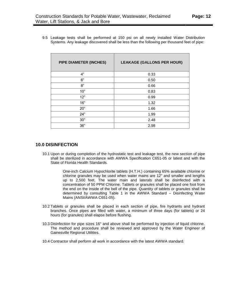
9.5 Leakage tests shall be performed at 150 psi on all newly installed Water Distribution Systems. Any leakage discovered shall be less than the following per thousand feet of pipe:
PIPE DIAMETER (INCHES) LEAKAGE (GALLONS PER HOUR)
4” 0.33
6” 0.50
8” 0.66
10” 0.83
12” 0.99
16” 1.32
20” 1.66
24” 1.99
30” 2.48
36” 2.98
10.0 DISINFECTION
10.1 Upon or during completion of the hydrostatic test and leakage test, the new section of pipe shall be sterilized in accordance with AWWA Specification C651-05 or latest and with the State of Florida Health Standards.
One-inch Calcium Hypochlorite tablets (H.T.H.) containing 65% available chlorine or chlorine granules may be used when water mains are 12" and smaller and lengths up to 2,500 feet. The water main and laterals shall be disinfected with a concentration of 50 PPM Chlorine. Tablets or granules shall be placed one foot from the end on the inside of the bell of the pipe. Quantity of tablets or granules shall be determined by consulting Table 1 in the AWWA Standard – Disinfecting Water Mains (ANSI/AWWA C651-05).
10.2 Tablets or granules shall be placed in each section of pipe, fire hydrants and hydrant
branches. Once pipes are filled with water, a minimum of three days (for tablets) or 24 hours (for granules) shall elapse before flushing.
10.3 Disinfection for pipe sizes 16" and above shall be performed by injection of liquid chlorine.
The method and procedure shall be reviewed and approved by the Water Engineer of Gainesville Regional Utilities.
10.4 Contractor shall perform all work in accordance with the latest AWWA standard.
Construction Standards for Potable Water, Wastewater, Reclaimed Water, Lift Stations, & Jack and Bore
Page: 13
10.5 NOTE: Contractor shall coordinate with GRU Inspector prior to disinfection and pressure
testing, and then coordinate with Inspector, who shall coordinate with Murphree WTP staff to take two water samples for bacteriological testing on two consecutive days (see Appendix B – Contactor Responsibilities)
11.0 FINAL ACCEPTANCE
3.1 Upon completion of the work, all waste materials or other debris caused by or accumulated as a result of the job shall be removed from the site. Any depressions resulting from settlement or backfilled trenches shall be refilled. Any seeding and mulching or sprigging and mulching, or sodding of the ground surface shall be conducted in accordance with the Drawings or as required by the Federal Government, State, County, or Gainesville Regional Utilities.
3.2 Contractor shall coordinate with Inspector to arrange a date and time for “walkthrough” with
Water Department (note: before walkthrough, all mains must be flushed, hydrant plumbing and valve boxes brought to grade, and services shall be vertical with caps off). A written report of discrepancies (if any) shall be prepared by the Water Department and given to the Inspector and Contractor.
3.3 Contractor shall notify Inspector when discrepancies are repaired so that Inspector may
coordinate with Water Department for re-inspection.
3.4 When the system has passed inspection, Contractor shall furnish record drawings and certified costs. Inspector shall then close-out job, and a Completion Letter shall be sent by GRU to the Developer, Engineer of Record, and Contractor. There shall be a one (1) year warranty on the Water System. At the end of one (1) year the system shall be inspected for any defects and shall be repaired accordingly by the Contractor that installed the Water Distribution System.

Construction Standards for Potable Water, Wastewater, Reclaimed Water, Lift Stations, & Jack and Bore
Page: 14
Section II
Gainesville Regional Utilities
Wastewater Construction Standards
Construction Standards for Potable Water, Wastewater, Reclaimed Water, Lift Stations, & Jack and Bore
Page: 15
1.0 SCOPE
1.1 The purpose of and intent of these Standards and the accompanying Construction Details is to provide construction services for the installation or modification of a WASTEWATER SYSTEM.
1.2 Engineers, Developers, Contractors, Inspectors, and others concerned with wastewater
construction shall perform all work in accordance with these requirements. Any modifications to these standards shall require the Wastewater Engineer's approval.
2.0 INSPECTION AND DISPOSITION OF MATERIALS
2.1 Material delivered to the job site shall be inspected. Materials found during inspection or during the progress of the work to have cracks, chips, flaws, surface abrasions, cracked linings, or other defects shall be rejected and removed from the job site without delay. All materials delivered to the job site shall be in accordance with the Approved Water/Wastewater Materials Manual.
2.2 Pipe delivered to the job site shall be unloaded adjacent to or near the place where it is to be
installed. Materials shall be loaded and unloaded by a loader, lifting hoist, or skidding so as to avoid shock and prevent damage. Materials unloaded by skidways shall not be skipped or rolled against materials already on the ground.
3.0 PROTECTION OF PROPERTY AND OBSTRUCTIONS
3.1 Temporary supports and/or adequate protection and maintenance shall be installed on all underground and surface structures encountered in the progress of the work. Structures that have been disturbed shall be restored upon completion of the work.
3.2 Underground Utilities shall be notified and utility locates performed (call 811) prior to
beginning construction. Any known obstructions shall be shown on the Drawings. The utmost caution shall be taken in all operations to avoid damage to existing obstructions (for example, pipes, cables, conduit, utility poles, structures, etc.) whether or not shown on the Drawings.
3.3 Existing utilities shall be kept in operation by temporary lines, temporary pumps, or other
means provided for continuous operation of utilities. All of this work shall be installed, maintained, operated, and removed upon completion of the job. In cases where a bypass is required. The Contractor shall provide and maintain adequate equipment, two (2) pumps with auto switchover system and call box with a maximum of thirty minute response, piping, tankers, and other necessary appurtenances in order to maintain continuous and reliable wastewater service in all wastewater lines as required for construction. All materials, equipment, and labor necessary to complete the repair, replacement or rehabilitation shall
Construction Standards for Potable Water, Wastewater, Reclaimed Water, Lift Stations, & Jack and Bore
Page: 16
be on the job site prior to isolating the gravity main segment, manhole, or pump station. The Contractor shall demonstrate that the pumping system is in good working order and is sufficiently sized to successfully handle flows by performing a test run for a period of 24 hours prior to beginning the work.
4.0 TRENCH PREPARATION
4.1 The trench shall be opened so that the pipe can be installed to the alignment and depth required. The trench shall be excavated only so far in advance of pipe installation as to insure proper installation in accordance with Gainesville Regional Utilities Construction Standards.
4.2 The trench shall be excavated to the depth required so as to provide a uniform and
continuous bearing support for the pipe on undisturbed ground. Bell holes shall be provided at each joint to permit jointing to be made properly and inspected.
4.3 During excavation, if ashes, cinders, refuse, or other organic materials considered unstable
are uncovered at the bottom of the trench or at subgrade, it shall be removed and backfilled with approved material.
4.4 Approved backfill material shall be tamped in layers so as to provide a uniform and
continuous bearing characteristic of that area's soil condition.
4.5 Excavated material shall be piled in such a manner that it will not endanger the work, or obstruct natural water courses, sidewalks, or driveways. Fire hydrants under pressure, valve pit covers, valve boxes, fire and police call boxes, or other utility controls shall be left unobstructed and accessible at all times. Gutters shall be kept clear or other satisfactory provisions made for street drainage. All materials which are suitable for reuse in restoring the surface shall be kept separate from any unacceptable excavated material.
4.6 Open cut trenches shall be sheeted and braced as required by any governing State law,
municipal ordinances, OSHA Standards.
4.7 Sheeting and bracing which have been ordered left in place must be removed to a depth of four (4) feet below the established grade or the existing surface, whichever is lower. Trench bracing, except that which must be left in place, may be removed after the backfilling has been completed or has been brought up to such an elevation as to permit its safe removal. The use of a trench box may be allowed unless sheeting and bracing is required by the Engineer.
4.8 Water shall not be allowed in the trench at any time. An adequate supply of well points,
headers, and pumps, all in first class operating condition, may be used to remove the water. The use of gravel and pumps shall also be an acceptable means of removing the water. The trench shall be excavated no more than the available pumping facilities are capable of handling. This discharge from pumps shall be routed to natural drainage channels or emptied into drains or storm sewers, or as required by EPA, FDEP, the Water Management District, or other agencies.
Construction Standards for Potable Water, Wastewater, Reclaimed Water, Lift Stations, & Jack and Bore
Page: 17
5.0 HANDLING AND CUTTING PIPE
5.1 Every care shall be taken in handling and laying pipe and fittings to avoid damaging the pipe, scratching or marring machined surfaces, and abrasion of the pipe coating.
5.2 Lined pipe or fittings must be handled only from the outside of the pipe and fittings. No forks,
chains, straps, hooks, etc. shall be placed inside the pipe and fittings for lifting, positioning, or laying. If damaged, the material shall be repaired in accordance with the liner manufacturer’s recommendations and to GRU’s satisfaction.
5.3 Except as otherwise approved, all cutting shall be done with a power driven cut off saw. All
cut ends shall be examined for possible cracks caused by cutting. The coating on cut ends must be repaired per manufacturer’s specifications.
6.0 FORCE MAIN
6.1 Gainesville Regional Utilities Water and Wastewater Engineering Department shall be notified forty-eight (48) hours prior to beginning construction. Inspectors may require a visual inspection on all piping systems installed without notification of Gainesville Regional Utilities.
6.2 Force mains shall be constructed to line and grade as indicated on the Drawings. Fittings
shall be epoxy lined ductile iron mechanical joint with restraints as specified in the Construction Details. Epoxy lined ductile iron pipe shall be installed only where indicated on GRU approved plans. Materials installed shall be in accordance with the materials indicated in the Gainesville Regional Utilities Approved Materials Manual.
6.3 The Engineer and Contractor shall adjust the planned location of Air Release Valves (ARVs)
to the actual high points of the force main. The Contractor, with the Engineer’s approval, should install additional air release valves at changes in elevation of 2 feet or greater due to actual field conditions or other conditions not identified on the approved plans. As-builts will indicate the location and elevations of all ARVs. Pressure testing of force mains should be performed against the air release assembly isolation valve. After successful pressure testing, the contractor shall verify that all air release assembly isolation valves have been opened.
6.4 Material items not included in the GRU Approved Materials Manual shall not be installed.
Specialty items shall be approved by Gainesville Regional Utilities Water/Wastewater Engineering Department, prior to installation. The entire Wastewater System shall be installed as specified on the Drawing, and in accordance to the Gainesville Regional Utilities Wastewater Construction standards.
6.5 The bottom of the trench shall not be excavated below the specified grade. If undercutting
occurs, the bottom of the trench shall be brought up to the original grade with approved materials, thoroughly compacted, as directed by Gainesville Regional Utilities.
6.6 Before placing pipe into the trench, the outside of the spigot and the inside of the bell shall
be wiped clean and dry, free from oil and grease. Every precaution shall be taken to prevent
Construction Standards for Potable Water, Wastewater, Reclaimed Water, Lift Stations, & Jack and Bore
Page: 18
foreign materials from entering the pipe. During laying operation, no debris, tools, clothing or other material shall be placed in the pipe.
6.7 After placing a length of pipe in the trench, the spigot end shall be centered in the bell; the
pipe pushed home (to the manufacturer’s mark for PVC pipe), brought to correct alignment, and covered with an approved backfill material. If PVC plastic pipe is installed, a green insulated, solid conductor, 10 gauge copper wire shall be laid on top of the pipe and taped every ten feet for location purposes. The wire shall be stubbed out at each ARV and valve box, with a dummy valve box added at 500’ intervals when necessary.
6.8 When pipe laying is not in progress, the open ends of pipe shall be closed by a water tight
plug or other approved means. This provision shall apply during the noon hour as well as overnight. If water is in the trench, the seal shall remain in place until the trench is pumped completely dry.
6.9 Backfilling material shall be free from cinders, ashes, refuse, vegetable or organic material,
boulders, rocks, stones, or other materials which are considered unsuitable. When backfill material is not specified on the Drawings backfilling with the excavated material may be acceptable provided that such material is suitable for backfilling.
6.10 Placement of the embedment materials is the most important part of pipe laying. The five
groups of embedment materials listed include a number of processed materials plus the soil types defined according to the United Soil Classification System (USCS) in ASTM D-2487, Standard Method of Classification of Soils for Engineering Purposes. Bedding may be required in poor soil conditions. Class IV and Class V material shall not be used for bedding, haunching, or initial backfilling.
6.11 After placement of the pipe the soil shall be consolidated to the springline of the pipe by
either hand tamping the soil in place, or using a hand operated tamping machine. From the springline of the pipe to two (2) feet above the pipe, the soil shall be carefully backfilled in 6” lifts. After placement and compaction of the embedment material, the balance of the backfill material may be machine placed or as required by the Inspector and shall not contain any large rocks or debris. All work under pavement shall be conducted in accordance with any state, county, or local requirements.
6.12 Mechanical joints shall be made up in strict accordance with the manufacturer's
specifications. Gaskets shall be lubricated and evenly seated, the gland placed in position, with the bolts hand tightened before final tightening by wrenches. Tighten T-bolts to the recommended torque. Do not over-torque to avoid crushing the gasket. Maintain the same overall gap between the gland and the MJ fitting face by tightening the T-bolts in a uniform criss-cross pattern (12 o’clock, 6 o’clock, 3 o’clock, 9 o’clock, etc.) until proper torque is achieved. Using a torque wrench is highly recommended. Wait 10 minutes to allow gasket to relax, and retighten bolts to proper torque.
6.13 Push-on joints shall be made up in strict accordance with the manufacturer's specifications.
The bell shall be carefully cleaned before the gasket is inserted. The spigot shall be cleaned while suspended above the trench. The joint shall then be lubricated with an approved, non-toxic lubricant and the pipe pushed home (note: on PVC pipe, this is indicated by the manufacturer’s mark).
Construction Standards for Potable Water, Wastewater, Reclaimed Water, Lift Stations, & Jack and Bore
Page: 19
6.14 Maximum joint deflection of ductile iron and PVC pipe shall be limited to 80% of the pipe
manufacturer’s recommendation. PVC pipe may be bent to a radius 20% greater than the manufacturer’s recommendation. If a bend is needed to facilitate construction, but has not been included on the design drawings, one must be added as directed by the Engineer.
6.15 Valves and fittings shall be set and joined to the pipe in the proper location as specified in
the Drawings. A valve box shall be provided for every valve. This valve box shall not transmit shock or stress to the valve and shall be centered and plumb over the wrench nut of the valve, with the box cover flush with the final grade or as may be specified in the Drawings.
6.16 Mechanical joint restraint shall be provided as specified in the Construction Details. 6.17 Thrust blocking may be installed in certain cases as specified on the Drawings and in
accordance with the Gainesville Regional Utilities Wastewater Construction Standards. Thrust blocks installed on force mains shall be calculated using a design pressure of l00 psi. All thrust blocks shall be a minimum of 2,500 psi ready-mix concrete. Hand mixing of concrete at the job site shall not be permitted.
6.18 NOTE: Before backfilling is complete, Contractor shall coordinate with GRU Inspector for a
visual inspection of all mechanical joint restraints and for proper backfill (see Appendix B – Contractor Responsibilities).
7.0 GRAVITY COLLECTION SYSTEM
7.1 Gainesville Regional Utilities Water and Wastewater Engineering shall be notified forty-eight (48) hours prior to beginning construction. Inspectors may require a visual inspection on all piping systems installed without notification of the Gainesville Regional Utilities.
7.2 Gravity collection mains shall be constructed of the type and size indicated on the
Drawings. All fittings shall be mechanical joint. Solvent weld joints are not acceptable. Ductile iron pipe shall be installed only if indicated on the GRU approved plans.
7.3 All materials installed shall be in accordance with the materials indicated in the Gainesville
Regional Utilities Approved Materials Manual. Material that is not included in the manual shall not be installed. Prior to installation specialty items shall be approved by the Gainesville Regional Utilities Water/Wastewater Engineering Department.
7.4 Gravity sewer mains shall be installed as specified on the Drawings and in accordance with
the Gainesville Regional Utilities Wastewater Construction Standards. 7.5 The bottom of the trench shall not be excavated below the specified grade. If undercutting
occurs, the bottom of the trench shall be brought up to the original grade with approved material, thoroughly compacted, as directed by the Gainesville Regional Utilities.
Construction Standards for Potable Water, Wastewater, Reclaimed Water, Lift Stations, & Jack and Bore
Page: 20
7.6 Before placing the pipe into the trench, the outside of the spigot and the inside of the bell
shall be wiped clean and dry, free from oil and grease. Every precaution shall be taken to prevent foreign material from entering the pipe. During laying operation, no debris, tools, clothing or other material shall be placed into the pipe.
7.7 Gravity sewer mains shall be installed with a pipe laser. Laterals may be installed with
mason’s lines and batter boards. The batter board shall be erected to a predetermined alignment and grade. Two mason’s lines with a minimum of 75 feet in length shall be tightly stretched and supported with batter boards and at intervals not exceeding 25 feet.
7.8 After placing the length of pipe in the trench, the spigot end shall be centered in the bell,
forced home, and brought to the correct alignment and grade. The pipe shall be covered with an approved backfill material.
7.9 When pipe laying is not in progress, the open ends of pipe shall be closed by a watertight
plug or other approved means. This provision shall apply during the noon hour as well as overnight. If water is in the trench, the seal shall remain in place until the trench is pumped completely dry.
7.10 Backfilling material shall be free from cinders, ashes, refuse, vegetable or organic material,
boulders, rocks, stones, or other material which is considered unsuitable. When backfill material is not specified on the Drawings, backfilling with the excavated material may be acceptable provided that such material is suitable for backfilling.
7.11 Placement of the embedment materials is the most important part of pipe laying. The five
groups of embedment materials plus the soil types defined according to the United Soil Classification System (USCS) in ASTM D-2487, Standard Method of Classification of Soils for Engineering Purposes. Bedding may be required in poor soil conditions. Class IV and Class V material shall not be used for bedding, haunching, or initial backfill.
7.12 When rock and pump method is used instead of well pointing, Class I material shall be
installed for bedding. Sufficient amounts of Class II or Class III material shall be added to fill the voids created by using rock. Pumps shall be moved in intervals to ensure the migration of Class II or Class III material. Discharge from the pumps shall not be emptied into the pipe which is being installed.
7.13 After pipe has been placed into the trench according to the alignment and grade indicated
on the Drawing, haunching material shall be placed to the springline of the pipe and hand tamped. Care shall be taken to ensure sufficient amounts of material have been worked under the haunches of the pipe to provide adequate side support. Precautions shall be taken to prevent movement of the pipe.
7.14 Place initial backfill within 24”-30" above the top of the pipe and hand tamp in 6”-12”
increments. The minimum cover on all gravity sewer mains shall be thirty-six (36) inches. At least forty-eight (48) inches of cover shall be provided for PVC mains before using a mobile trench compactor of the hydro hammer type.
7.15 Final backfill may be machine placed. Materials that complete final backfill operation need
not be as carefully selected as the initial backfill. All work under pavement shall be
Construction Standards for Potable Water, Wastewater, Reclaimed Water, Lift Stations, & Jack and Bore
Page: 21
conducted in accordance with any state, county or local requirements. Communication with them is the Contractor’s responsibility.
7.16 The location of all laterals shall be shown on the Drawings. All materials installed shall be in
accordance with the materials indicated in the Gainesville Regional Utilities Approved Materials Manual.
7.17 Wyes of proper size shall be installed in the wastewater collection system at the locations
shown on the Drawings. The wyes, unless otherwise specified, shall be inclined upward at an angle of not more than 45 degrees from the horizontal. Each wye shall be fitted with a short radius curve, connected with a lateral and extended to the property line. Tee-wyes are not acceptable. Solvent-weld saddles are not acceptable.
7.18 Each lateral shall contain a clean-out. The clean-outs shall be installed at the location
shown on the Drawings and in accordance with the Gainesville Regional Utilities Wastewater Construction Standards. All clean-outs shall be installed initially a minimum of four feet above final grade during new construction. Prior to final acceptance and after completion of the smoke test of the wastewater collection system, all clean outs shall be lowered to final grade and capped, as specified in the Construction Details.
7.19 NOTE: Before backfilling is complete, Contractor shall coordinate with GRU Inspector for a
visual inspection to confirm proper grade per GRU Standards and drawings on mainline, wyes, and laterals and for proper backfill (see Appendix B – Contractor Responsibilities).
8.0 MANHOLES
8.1 Manholes shall be constructed at the location shown on the Drawings. The manholes may be either constructed of bricks and mortar or precast concrete sections. All precast manhole sections shall conform to A.S.T.M. Specification C 478-73 or latest revision. Manhole sections shall be joined and sealed with "Ram-Nek" sealer.
8.2 During installation of the manhole the pit shall remain dry. All materials installed shall be in
accordance with the materials indicated in the Gainesville Regional Utilities Approved Materials Manual.
8.3 Precast base sections without a bottom shall be installed into a minimum of 2,500 psi @ 28
days ready mix concrete. Hand mixing of concrete at the job site shall not be permitted. Form boards shall be installed on all concrete slab construction. The concrete slab shall be a square two feet wider than the outside diameter of the base section with a minimum thickness of twelve (12) inches. The concrete slab shall be installed to the proper grade and against undisturbed earth. Undercutting and backfilling to establish proper grade shall not be acceptable. Sufficient time shall elapse after the concrete has been poured so that the base section may be centered, embedded into the slab and stand plumb. All connections into the base section shall form a watertight seal.
8.4 Precast base sections with a bottom shall be installed on undisturbed earth. Bedding is
required when the soil conditions are wet or when the soil is Class IV or Class V material. The bedding shall be 4"-6” (100-150 mm) Class I, Class II, or Class III material. The
Construction Standards for Potable Water, Wastewater, Reclaimed Water, Lift Stations, & Jack and Bore
Page: 22
bedding of Class II and Class III material shall be hand tamped, uniform and no finer than the foundation. When utilizing Class I material, sufficient amounts of Class II or class III material shall be added to fill the voids created by the use of Class I material. All connections into the manhole bottom shall form a watertight seal.
8.5 Manhole bottoms shall contain inverts uniformly formed with Type II lean cement hand mix
with brick and sloped to the centerline of the pipe. Where more than one pipe enters a manhole, various channels shall be formed to provide an invert for each pipe.
8.6 Precast top sections shall be eccentric cones. The top section shall be installed so that the
cone is either a minimum of six (6) inches from the final grade or a maximum of twenty-four (24) inches from the final grade.
8.7 Bricks and mortar shall be used to bring the manhole ring and cover up to the final grade.
The ring and cover shall be twenty-four (24) inches in diameter, designed for traffic loading and conforming to D.O.T. (Florida Department of Transportation) Specifications.
8.8 New installations requiring drop construction shall be installed outside of the manhole.
Subject to approval of the Gainesville Regional Utilities Wastewater Engineer inside drops may be installed on existing manholes. All ductile iron fittings shall be mechanical joint. Plain end fittings extending into manhole section are acceptable.
8.9 All connections into the manhole section shall form a watertight seal. The base of the drop
and one joint of pipe shall be backfilled and hand tamped in layers and within one foot above the top of the pipe. The maximum height between the base of the drop and the top of the invert shall be twenty-four (24) inches.
8.10 Manholes for air release valves shall be constructed at the location shown on the Drawings.
All precast base sections shall have an inside diameter of forty-eight (48) inches. Flat top slabs may be installed with a manhole ring and cover cast into the slab. The minimum thickness of the flat top shall be six (6) inches.
8.11 A 12 foot wide stabilized access road, stabilized to a minimum LBR 30, shall be provided to
all manholes located within easements. The access road shall be designed to provide for adequate drainage and to prevent erosion from stormwater runoff. Maximum grade shall be 5% where feasible, but in no case greater than 10%. A Tee-shaped vehicle turn around area shall be provided at the end of all dead end access roads to provide the ability to maneuver a large utility truck in the road. Each leg of the tee shall be minimum 14’ wide and 25’ long measured from the near edge of the adjacent perpendicular road leg.
9.0 LIFT STATIONS
9.1 All lift stations shall be constructed at the locations shown on the Drawings. The lift stations may be constructed of pre-cast concrete sections. Each pre-cast section installed shall be joined to form a watertight joint with “Ram-Nek” sealer or equivalent. All lift stations shall be constructed in accordance with Gainesville Regional Utilities Standards.
Construction Standards for Potable Water, Wastewater, Reclaimed Water, Lift Stations, & Jack and Bore
Page: 23
10.0 PAVING, CURB, GUTTER, AND WALKWAY WORK
10.1 When open ditch construction of pipe beneath paving is permitted, the pavement, curb and gutter, driveway, and walkway shall be removed to neat lines of a sufficient width to allow proper installation of the pipe work.
10.2 Signal lights, warning signs, and barricades shall be installed and maintained as required
for adequate safety. 10.3 No pavement base shall be replaced before the ditch backfill has been inspected and
approved. Density and compaction tests may be required by the authority having jurisdiction over the street, road, or highway involved.
10.4 Pavement shall be replaced in accordance with the "Florida Department of Transportation,
Standard Specifications for Road and Bridge Construction", or latest edition or as required by Gainesville Regional Utilities.
10.5 Curb and gutter shall be replaced with a new concrete unit poured-in-place and having the
same cross section as the original curb removed. The concrete shall be thoroughly cured. Backfill under concrete work shall be thoroughly compacted and the sub-grade approved before any concrete may be poured.
10.6 Concrete walkways and driveways shall be replaced with concrete of the same cross
section as the original walk or driveway. The concrete shall be thoroughly cured. Backfill under concrete work shall be thoroughly compacted and the sub-grade approved before any concrete may be poured.
11.0 TESTING
11.1 All wastewater force mains shall be hydrostatically tested at a gauge pressure of 100 psi upon completion of the line. The section of pipe under test shall be slowly filled with water to the specified test pressure. All water used shall be metered during the tests. The lowest elevation point on the section being tested shall be determined and any corrections necessary shall be corrected to the elevation of the test gauge by means of a hand pump, gasoline, or electric test pump connected to the pipe.
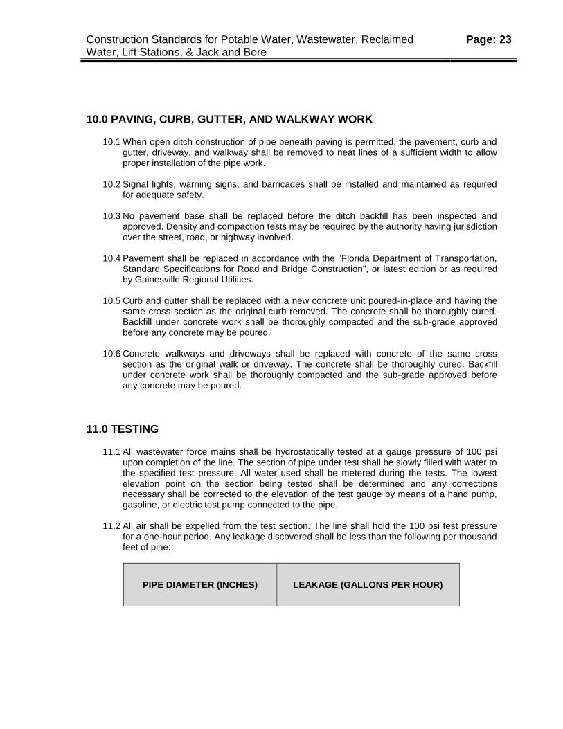
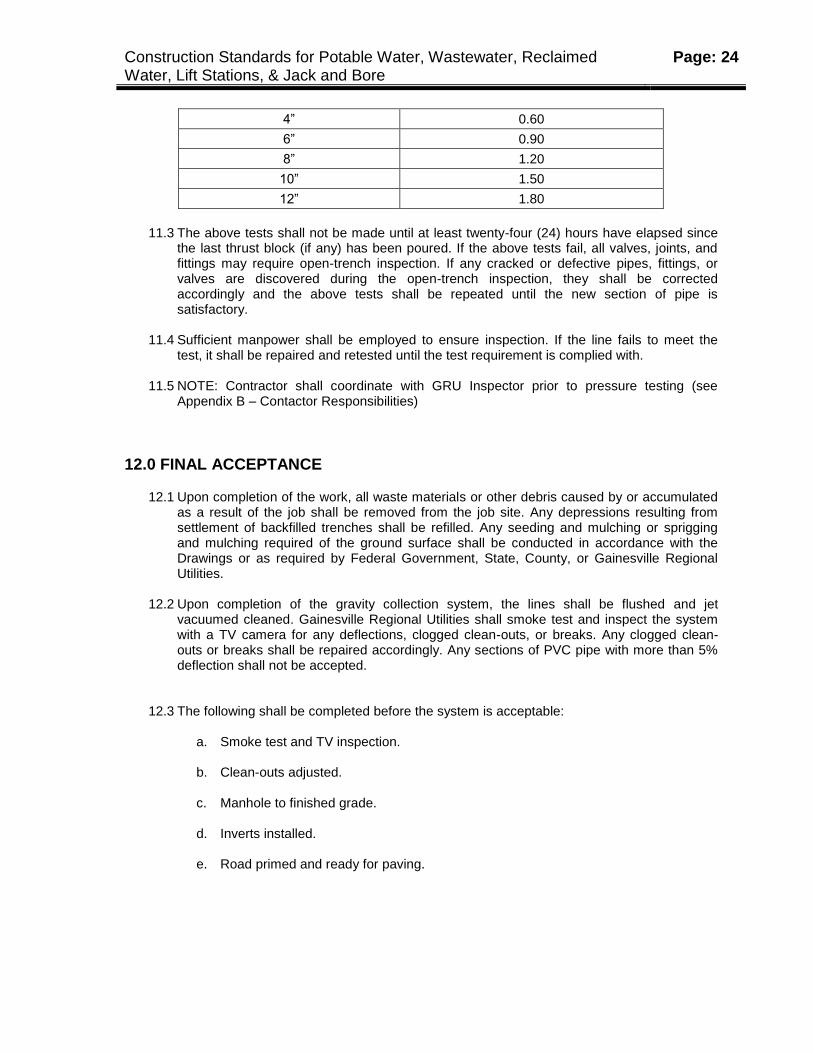
11.2 All air shall be expelled from the test section. The line shall hold the 100 psi test pressure
for a one-hour period. Any leakage discovered shall be less than the following per thousand feet of pine:
PIPE DIAMETER (INCHES) LEAKAGE (GALLONS PER HOUR)
Construction Standards for Potable Water, Wastewater, Reclaimed Water, Lift Stations, & Jack and Bore
Page: 24
4” 0.60
6” 0.90
8” 1.20
10” 1.50
12” 1.80
11.3 The above tests shall not be made until at least twenty-four (24) hours have elapsed since
the last thrust block (if any) has been poured. If the above tests fail, all valves, joints, and fittings may require open-trench inspection. If any cracked or defective pipes, fittings, or valves are discovered during the open-trench inspection, they shall be corrected accordingly and the above tests shall be repeated until the new section of pipe is satisfactory.
11.4 Sufficient manpower shall be employed to ensure inspection. If the line fails to meet the
test, it shall be repaired and retested until the test requirement is complied with.
11.5 NOTE: Contractor shall coordinate with GRU Inspector prior to pressure testing (see Appendix B – Contactor Responsibilities)
12.0 FINAL ACCEPTANCE
12.1 Upon completion of the work, all waste materials or other debris caused by or accumulated as a result of the job shall be removed from the job site. Any depressions resulting from settlement of backfilled trenches shall be refilled. Any seeding and mulching or sprigging and mulching required of the ground surface shall be conducted in accordance with the Drawings or as required by Federal Government, State, County, or Gainesville Regional Utilities.
12.2 Upon completion of the gravity collection system, the lines shall be flushed and jet
vacuumed cleaned. Gainesville Regional Utilities shall smoke test and inspect the system with a TV camera for any deflections, clogged clean-outs, or breaks. Any clogged clean-outs or breaks shall be repaired accordingly. Any sections of PVC pipe with more than 5% deflection shall not be accepted.
12.3 The following shall be completed before the system is acceptable:
a. Smoke test and TV inspection. b. Clean-outs adjusted.
c. Manhole to finished grade.
d. Inverts installed.
e. Road primed and ready for paving.
Construction Standards for Potable Water, Wastewater, Reclaimed Water, Lift Stations, & Jack and Bore
Page: 25
12.4 Contractor shall coordinate with Inspector to arrange for TV inspection of wastewater
system (note: prior to TV inspection, laterals must be flushed, the entire circumference of mains jet cleaned, and all debris removed). A written report of any discrepancies found shall be prepared by the Wastewater Department and provided to the Inspector.
12.5 Contractor shall notify Inspector when discrepancies are repaired so that Inspector may
coordinate with Wastewater Department for re-inspection.
12.6 When the system has passed inspection, Contractor shall furnish record drawings and certified costs. Inspector shall then close-out job, and a Completion Letter shall be sent by GRU to the Developer, Engineer of Record, and Contractor. There shall be a one (l) year warranty on the Wastewater System. At the end of one (1) year the system shall be inspected with a TV camera and any defects discovered shall be repaired accordingly by the Contractor that installed the Wastewater System.
12.7 The point of connection to the GRU system must be plugged with a mechanical plug until
construction is complete, lines flushed, and the GRU W/WW Inspector approves removal.
Construction Standards for Potable Water, Wastewater, Reclaimed Water, Lift Stations, & Jack and Bore
Page: 26
Section III
Gainesville Regional Utilities
Reclaimed Water Construction Standards
Construction Standards for Potable Water, Wastewater, Reclaimed Water, Lift Stations, & Jack and Bore
Page: 27
1.0 SCOPE
1.1 The purpose and intent of these Standards and the accompanying Drawings is to provide for the furnishing and installation of a RECLAIMED WATER TRANSMISSION AND DISTRIBUTION SYSTEM.
1.2 Engineers, Developers, Contractors, Inspectors, and others concerned with reclaimed water
construction shall perform all work in accordance with these requirements. Any modifications to these standards shall require GRU's Engineer's approval.
1.3 All Reclaimed Water Main Construction methods and materials, including piping, valves, fire
hydrants etc. and associated appurtenances shall conform to current GRU and AWWA standards.
2.0 INSPECTION AND DISPOSITION OF MATERIALS
2.1 Material delivered to the job site shall be inspected. Materials found during inspection or during the progress of the work to have cracks, flaws, surface abrasions, cracked linings, or other defects shall be rejected and removed from the job site without delay. All materials delivered to the job site shall be in accordance with the Approved Water Materials Manual.
2.2 Pipe delivered to the job site shall be unloaded opposite or near the place where it is to be
installed. Materials shall be loaded and unloaded by lifting hoists or skidding so as to avoid shock and prevent damage. Materials unloaded by skidways shall not be skipped or rolled against materials already on the ground.
3.0 PROTECTION OF PROPERTY AND OBSTRUCTIONS
3.1 Temporary supports and/or adequate protection and maintenance shall be installed on all underground and surface structures encountered in the progress of the work. Structures that have been disturbed shall be restored upon completion of the work.
3.2 Underground Utilities shall be notified and utility locates scheduled (call 811) prior to
beginning construction. Any known obstructions shall be shown on the Drawings. The utmost caution shall be taken in all operations to avoid damage to existing obstructions (for example, pipes, cables, conduit, utility poles, structures, etc.) whether or not shown on the Drawings.
3.3 Existing utilities shall be kept in operation by temporary lines, temporary pumps, or other
means provided for continuous operation of utilities. All this work shall be installed, maintained, operated, and removed upon completion of the job.
Construction Standards for Potable Water, Wastewater, Reclaimed Water, Lift Stations, & Jack and Bore
Page: 28
4.0 TRENCH PREPARATION
4.1 The trench shall be opened so that the pipe can be installed to the alignment and depth required. The trench shall be excavated only so far in advance of pipe installation as to insure proper installation in accordance with Gainesville Regional Utilities Construction Standards.
4.2 The trench shall be excavated to the depth required so as to provide a uniform and
continuous bearing support for the pipe on undisturbed ground. Bell holes shall be provided at each joint to permit jointing to be made properly and inspected.
4.3 During excavation, if ashes, cinders, refuse, or other organic material considered unstable is
uncovered at the bottom of the trench or at subgrade, it shall be removed and backfilled with approved material.
4.4 Approved backfill material shall be tamped in layers so as to provide a uniform and
continuous bearing characteristic of that area's soil condition. Where the bottom of the trench at subgrade consists of unstable material to such a degree that it cannot be removed and replaced with an approved material to support the pipe properly, a suitable foundation shall be constructed in accordance with Gainesville Regional Utilities Standards.
4.5 Excavated material shall be piled in such a manner that it will not endanger the work, or
obstruct natural water courses, sidewalks, or driveways. Fire hydrants under pressure, valve pit covers, valve boxes, fire and police call boxes, or other utility controls shall be left unobstructed and accessible at all times. Gutters shall be kept clear or other satisfactory provisions made for street drainage. All surface materials which are suitable for reuse in restoring the surface shall be kept separate from any unacceptable excavated material.
4.6 Open cut trenches shall be sheeted and braced as required by any governing State law,
municipal ordinances, OSHA Standards, or as may be necessary to protect life, property, or the work. When close sheeting is required, it shall be so driven as to prevent adjacent soil from entering the trench either below or through such sheeting.
4.7 Sheeting and bracing which have been ordered left in place must be removed for a distance
of three (3) feet below the established street grade or the existing surface of the street, whichever is lower. Trench bracing, except that which must be left in place, may be removed after the backfilling has been completed or has been brought up to such an elevation as to permit its safe removal. The use of a mule may be allowed unless sheeting and bracing is required by the Engineer.
4.8 Water shall not be allowed in the trench at any time. An adequate supply of well points,
headers, or pumps, all in first class operating condition, may be used to remove the water. The use of gravel and pumps shall also be an acceptable means of removing the water. The trench shall be excavated no more than the available pumping facilities are capable of handling. The discharge from pumps shall be routed to natural drainage channels or emptied into drains or storm sewers.
Construction Standards for Potable Water, Wastewater, Reclaimed Water, Lift Stations, & Jack and Bore
Page: 29
5.0 HANDLING AND CUTTING PIPE
5.1 Every care shall be taken in handling and laying pipe and fittings to avoid damaging the pipe, scratching or marring machined surfaces, and abrasion of the pipe coating.
5.2 Lined pipe and fittings must be handled only from the outside of the pipe and fittings. No
forks, chains, straps, hooks, etc. shall be placed inside the pipe and fittings for lifting, positioning, or laying. If damaged, the material shall be repaired in accordance with the liner manufacturer’s recommendations and to GRU’s satisfaction.
5.3 Except as otherwise approved, all cutting shall be done with a power driven cut off saw. All
cut ends shall be examined for possible cracks caused by cutting.
6.0 PIPELINE CONSTRUCTION
6.1 Gainesville Regional Utilities Water and Wastewater Engineering Department shall be notified forty-eight (48) hours prior to beginning construction. Inspectors may require a visual inspection on all piping systems installed without notification of Gainesville Regional Utilities.
6.2 Water mains shall be constructed as indicated on the Drawings. Fittings and valves shall be
mechanical joint, with restraints as specified in the Construction Details. Materials installed shall be in accordance the materials indicated in the Gainesville Regional Utilities Approved Materials Manual.
6.3 Any material items not included in the Approved Materials Manual shall not be installed.
Special items shall be approved by the Gainesville Region Utilities, Standards Division, prior to installation.
6.4 The bottom of the trench shall not be excavated below the specified grade. If undercutting
occurs, the bottom of the trench shall be brought up to the original grade with approved material, thoroughly compacted, as directed by Gainesville Regional Utilities.
6.5 Before placing pipe into the trench, the outside of the spigot and the inside of the bell shall
be wiped clean and dry, free from oil and grease. Every precaution shall be taken to prevent foreign material from entering the pipe. During layout operation, no debris, tools, clothing, or other material shall be placed into the pipe.
6.6 After placing a length of pipe in the trench, the spigot end shall be centered in the bell and
the pipe forced home, brought to correct alignment, and covered with an approved backfill material. Chlorine tablets shall be placed inside of the pipe near each bell. If plastic pipe is installed, an insulated, single conductor, 10 gauge copper wire shall lie on top of the pipe and be taped every ten feet for location purposes. Each fire hydrant shall have one wrap of the wire around the barrel located at final grade and connected to the wire on the water main.
6.7 When pipe laying is not in progress, the open ends of pipe shall be closed by a water tight
plug or other approved means. This provision shall apply during the noon hour as well as
Construction Standards for Potable Water, Wastewater, Reclaimed Water, Lift Stations, & Jack and Bore
Page: 30
overnight. If water is in the trench, the seal shall remain in place until the trench is pumped completely dry.
6.8 Backfilling material shall be free from cinders, ashes, refuse, vegetable or organic material,
boulders, rocks, stones, or other material which is considered unsuitable. When backfill material is not specified on the Drawings backfilling with the excavated material may be acceptable provided that such material is suitable for backfilling.
6.9 Placement of the embedment materials is the most important part of pipe laying. The five
groups of embedment materials listed include a number of processed materials plus the soil types defined according to the United Soil Classification System (USCS) in ASTM D-2487, Standard Method Classification of Soils for Engineering Purposes.
6.10 Special bedding may be required in poor soil conditions. After placement of the pipe the soil
shall be consolidated to the springline of the pipe by hand tamping the soil in place. From the springline of the pipe to twelve (12) inches above the pipe the soil shall be backfilled by hand and the soil consolidated by hand tamping. After placement and compaction of the embedment material, the balance of the backfill material may be machine placed or as required by the Inspector and shall not contain any large rocks or debris. All work under pavement shall be conducted in accordance with any state, county or local requirements and inspected by the agency.
6.11 Mechanical joints shall be made up in strict accordance with the manufacturer's
specifications. Gaskets shall be lubricated and evenly seated, the gland placed in position, with the bolts hand tightened before final tightening by wrenches. Tighten T-bolts to the recommended torque. Do not over-torque to avoid crushing the gasket. Maintain the same overall gap between the gland and the MJ fitting face by tightening the T-bolts in a uniform criss-cross pattern (12 o’clock, 6 o’clock, 3 o’clock, 9 o’clock) until proper torque is achieved. Using a torque wrench is highly recommended. For best results, wait 10 minutes to allow gasket to relax, and retighten bolts to proper torque.
6.12 Slip joints shall be made up in strict accordance with the manufacturer's specifications. The
bell shall be carefully cleaned before the gasket is inserted. The spigot shall be cleaned while suspended above the trench. The joint shall then be lubricated and the pipe shoved home (note: on PVC pipe, this is indicated by the manufacturer’s mark).
6.13 Maximum joint deflection of ductile iron and PVC pipe shall be limited to 80% of the pipe
manufacturer’s recommendation. PVC pipe may be bent to a radius 20% greater than the manufacturer’s recommendation. If a bend is needed to facilitate construction, but has not been included on the design drawings, one must be added as directed by the Engineer.
6.14 Valves and fittings shall be set and joined to the pipe in the proper location as specified in
the Drawings. A valve box shall be provided for every valve. The valve box shall not transmit shock or stress to the valve and shall be centered and plumb over the wrench nut of the valve, with the box cover flush with the final grade or as may be specified in the Drawings.
6.15 Mechanical joint restraint shall be provided as specified in the Construction Details.
Construction Standards for Potable Water, Wastewater, Reclaimed Water, Lift Stations, & Jack and Bore
Page: 31
6.16 Thrust blocks may be installed in certain cases as specified on the Drawings and in
accordance with the Gainesville Regional Utilities Water Construction Standards. Thrust blocks on water mains shall be calculated using a design pressure of 150 psi. All thrust blocks shall be a minimum of 2,500 psi ready-mix concrete. Hand mixing of concrete at the job site shall not be permitted.
6.17 NOTE: Before backfilling is complete, Contractor shall coordinate with GRU Inspector for a
visual inspection of all mechanical joint restraints and for proper backfill (see Appendix B – Contractor Responsibilities).
6.18 Except for multifamily dwellings, all service lines shall be either single or dual service. The
location of all service lines shall be shown on the Drawings. 6.19 Insulated, single conductor, 10 gauge copper wire shall be taped to all plastic pipe or tubing
for location purposes. The wire shall be stubbed out at the meter yoke located in the water meter box. The wire shall be connected to the wire required on plastic water mains.
6.20 The Developer’s Contractor shall install all Reclaimed Water Meter Assemblies. All
materials and construction of the service lines shall be in strict accordance with requirements of the Gainesville Regional Utilities Reclaimed Water Construction Standards and Approved Material Manual.
7.0 PAVING, CURB, GUTTER AND WALKWAY WORK
7.1 When open ditch construction of pipe beneath paving is permitted, the pavement, curb and gutter, driveway, and walkway shall be removed to neat lines of a sufficient width to allow proper installation of the pipe work.
7.2 Signal lights, warning signs, and barricades shall be installed and maintained as required for
adequate safety. 7.3 No pavement base shall be replaced before the ditch backfill has been inspected and
approved. Density and compaction tests may be required by the authority having jurisdiction over the street, road, or highway involved.
7.4 Pavement shall be replaced in accordance with the "Florida Department of Transportation,
Standard Specifications for Road and Bridge Construction", or latest edition or as required by Gainesville Regional Utilities.
7.5 Curb and gutter shall be replaced with a new concrete unit poured-in-place and having the
same cross section as the original curb removed. The concrete shall be thoroughly cured. Backfill under concrete work shall be thoroughly compacted and the sub-grade approved before any concrete may be poured.
7.6 Concrete walkways and driveways shall be replaced with concrete of the same cross-section
as the original walk or driveway. The concrete shall be thoroughly cured. Backfill under
Construction Standards for Potable Water, Wastewater, Reclaimed Water, Lift Stations, & Jack and Bore
Page: 32
concrete work shall be thoroughly compacted and the sub-grade approved before any concrete may be poured.
8.0 TESTING
8.1 All newly installed Reclaimed Water Distribution Systems which have been backfilled shall be hydrostatically tested at a gauge pressure of 150 psi. A leakage test shall be conducted at the above mentioned pressure. The leakage test may be conducted during the hydrostatic test. All tests shall be in accordance with AWWA Standard C 600-64, or latest revision.
8.2 The line under test shall be slowly filled with water at the specified test pressure. The lowest
elevation point on the section being tested shall be determined and any corrections necessary shall be corrected to the elevation of the test gauge by means of a hand pump, gasoline or electrically driven test pump connected to the pipe.
8.3 Blow-offs shall be installed at the end of the line under test. Before applying the specified
test pressure, all air shall be expelled from the test section including service connections. If blow-offs are not available at high places, taps at points of highest elevation shall be made before the test is made and plugs inserted after the test has been completed.
8.4 Reclaimed Water Mains shall hold the 150 psi test pressure for a one-hour test period;
sufficient manpower shall be employed to insure inspection. If the line fails to meet the test, it shall be repaired and retested until the test requirements are satisfied.
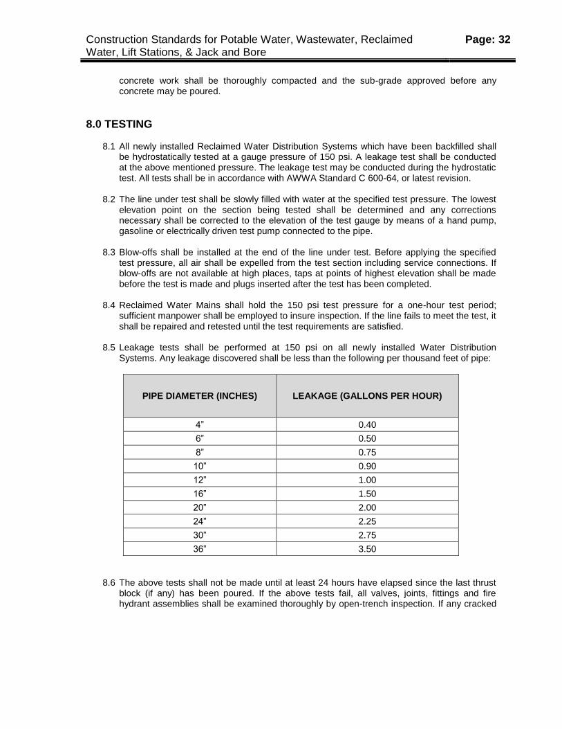
8.5 Leakage tests shall be performed at 150 psi on all newly installed Water Distribution
Systems. Any leakage discovered shall be less than the following per thousand feet of pipe:
PIPE DIAMETER (INCHES) LEAKAGE (GALLONS PER HOUR)
4” 0.40
6” 0.50
8” 0.75
10” 0.90
12” 1.00
16” 1.50
20” 2.00
24” 2.25
30” 2.75
36” 3.50
8.6 The above tests shall not be made until at least 24 hours have elapsed since the last thrust block (if any) has been poured. If the above tests fail, all valves, joints, fittings and fire hydrant assemblies shall be examined thoroughly by open-trench inspection. If any cracked
Construction Standards for Potable Water, Wastewater, Reclaimed Water, Lift Stations, & Jack and Bore
Page: 33
or defective pipes, fittings, fire hydrants or valves are discovered during the open-trench inspection, they shall be corrected accordingly and the above tests shall be repeated.
8.7 NOTE: Contractor shall coordinate with GRU Inspector prior to pressure testing, (see Appendix B – Contactor Responsibilities)
9.0 IDENTIFICATION
9.1 All reclaimed water pipes and above ground cross connection control devices accepted into the existing system shall be adequately identified by color. The color may be a characteristic of the pipe material, or permanently attached by means of an adhesive-backed tape or paint approved by the pipe manufacturer. There shall be a minimum of three colored stripes per length of pipe (located at 10:00, 12:00 and 2:00 when the pipe is installed) each a minimum of two inches wide. In addition, a three inch wide purple on silver background magnetic locator tape shall be installed along the length of the pipe, six inches above the top of the pipe. The magnetic tape shall read "Caution Reclaimed Water Line Below"
9.2 Adhesive tape shall have sufficient adhesive ability to remain attached to the pipe during
installation and backfilling procedures. The pipe surface must be clean and dry prior to application of the tape. Contractor shall take necessary care to insure that the adhesive tape remains in place.
10.0 FINAL ACCEPTANCE
10.1 Upon completion of the work, all waste materials or other debris caused by or accumulated as a result of the job shall be removed from the site. Any depressions resulting from settlement or backfilled trenches shall be refilled. Any seeding and mulching or sprigging and mulching required of the ground surface shall be conducted in accordance with the Drawings or as required by the Federal Government, State, County or Gainesville Regional Utilities.
10.2 Contractor shall coordinate with Inspector to arrange a date and time for “walkthrough” with
Wastewater Department (note: before walkthrough, all mains must be flushed, valve boxes brought to grade. A written report of discrepancies (if any) shall be prepared by the Wastewater Department and given to the Inspector and Contractor.
10.3 Contractor shall notify Inspector when discrepancies are repaired so that Inspector may
coordinate with Wastewater Department for re-inspection.
10.4 When the system has passed inspection, Contractor shall furnish record drawings and certified costs. Inspector shall then close-out job, and a Completion Letter shall be sent by GRU to the Developer, Engineer of Record, and Contractor. There shall be a one (1) year warranty on the Reclaimed Water System. At the end of one (1) year the system shall be inspected for any defects and shall be repaired accordingly by the Contractor that installed the Reclaimed Water Distribution System.
Construction Standards for Potable Water, Wastewater, Reclaimed Water, Lift Stations, & Jack and Bore
Page: 34
11.0 BACKFLOW PREVENTION REQUIREMENTS
11.1 All customers connected to a reclaimed water system shall install an approved backflow prevention device on their potable water supply line. The backflow prevention device shall be installed on the customer’s side of the water meter immediately after the water meter. The customer shall be responsible for the installation, operation and maintenance of the backflow prevention devise in accordance with accepted standards.
12.0 RECLAIMED WATER CONSTRUCTION STANDARD DRAWINGS
12.1 All reclaimed water main materials shall be installed in accordance with the Construction Details. Any additional materials or details not listed shall be installed in accordance with the applicable water main construction methods as described in the water main Construction Details.

Construction Standards for Potable Water, Wastewater, Reclaimed Water, Lift Stations, & Jack and Bore
Page: 35
Section IV
Gainesville Regional Utilities
Lift Station Construction Standards
Construction Standards for Potable Water, Wastewater, Reclaimed Water, Lift Stations, & Jack and Bore
Page: 36
1.0 SCOPE
1.1 The purpose and intent of these specifications is to provide a complete, working Wastewater Lift Station with submersible pumps, including electrical and mechanical accessories required. All work shall be in accordance with requirements of the Gainesville Regional Utilities System.
1.2 The Lift Station Construction Standards are divided into three (3) categories as follows:
Type I: Two (2) pump station 5-10 Hp range, three phase 208v, with Soft Start (20 hp and up) or Variable Frequency Drive (VFD) equipment. Wet well shall be sized 6' in diameter
. Type II: Two (2) pump stations in the 15-47 Hp range, three phase, 208v, with Soft Start (20
Hp and up) or Variable Frequency Drive (VFD) equipment, or 480v, with Soft Start or Variable Frequency Drive (VFD) equipment. Wet well shall be sized 8' or larger in diameter. (note: these type stations are designed for future upgrade and require sizing for the maximum anticipated loads.)
Type III: Three (3) or four (4) pump station 32and up Hp range, three phase 480v, with Soft
Start or Variable Frequency Drive (VFD) equipment. Wet well shall be designed and sized as required by the Engineer.
1.3 The pumps shall be manufactured by ITT Flygt Corporation (no substitute allowed). The
control panel shall be supplied by ITT Flygt/Xylem or approved equal.
2.0 DEVELOPER/ENGINEER RESPONSIBILITY
2.1 Utilities (GRU) shall be responsible for providing the Developer and/or Engineer with specifications for construction of Lift Stations. All work shall be in accordance with GRU DESIGN STANDARDS, DRAWING(S), and SPECIFICATIONS.
2.2 The Developer/Engineer shall be responsible for coordination of all design with Gainesville
Regional Utilities: ELECTRICAL, WATER, and WASTEWATER ENGINEERING DIVISIONS. 2.3 The Wastewater Engineering Division shall approve all design and determine the
requirements for future up-grading of all Lift Stations. Lift Stations requiring up-grading shall be designed and constructed to meet the anticipated flows of the development.
2.4 An overall layout of the entire development, including phasing, shall be required. Lift Stations
shall be designed for the ultimate build-out. Lift Stations located outside of the phase under development shall require an easement and access road as follows:
AN EASEMENT OR RIGHT OF WAY WITH A CROWNED ROADWAY AND ADEQUATE DRAINAGE SHALL BE PROVIDED. ROADWAY SHALL BE TWELVE (12) FEET WIDE, (LBR 30) WITH 6" OF LIMEROCK COMPACTED TO 95% MODIFIED PROCTOR. THE ROADWAY SHALL HAVE A SMOOTH FINISH, COMPACTED LIMEROCK WITH HOT SAND SEAL.
Construction Standards for Potable Water, Wastewater, Reclaimed Water, Lift Stations, & Jack and Bore
Page: 37
2.5 Lift Stations located within the phase under development shall require the following: AN EASEMENT OR RIGHT OF WAY WITH A CROWNED ROADWAY AND ADEQUATE DRAINAGE SHALL BE PROVIDED. ROADWAY SHALL BE FOURTEEN (14) FEET WIDE, (LBR 40) WITH 8" OF LIMEROCK COMPACTED TO 95% MODIFIED PROCTOR; THE ROADWAY SHALL HAVE A SMOOTH FINISH OF 1-1/4" ASPHALTIC CONCRETE. 2.6 Lift Station sites shall be 50' x 50' minimum complete with an entrance road and turn pad as
shown in the Construction Details. Fencing shall be required as shown on Gainesville Regional Utilities Wastewater Engineering standard Lift Station drawings.
3.0 PUMPS
3.1 Lift Stations shall be designed with minimum 5 horsepower pumps. The design of the pumps shall be such that each unit will be automatically connected to the discharge piping when lowered into place on the discharge connection.
3.2 The pump(s) shall be easily removable for inspection or service, requiring no bolts, nuts, or
other fastenings to be removed for this purpose and no need for personnel to enter pump well.
3.3 Each pump shall be fitted with a stainless steel cable, plastic coated, of adequate strength
and length to permit raising the pump for inspection and removal. 3.4 The pumps shall be provided with a tandem double mechanical seal running in an oil bath.
The seals shall be of lapped tungsten carbide, held in contact by separate springs. Conventional double mechanical seals with a spring assembly between the rotating faces, requiring constant differential pressure to effect sealing, are not acceptable.
3.5 The stator casing, oil casing, volute and impeller shall be of Class 30, gray iron construction,
with all external parts coming into contact with sewage protected by a coating of high build epoxy resistant to sewage. All external bolts and nuts shall be stainless steel. The impeller shall be non-clog design, capable of passing solids, fibrous material, heavy sludge, and constructed with a long thruway with no acute turns.
3.6 The pump motor shall be of Class F insulation, NEMA B design, watertight and air filled.
The pump motor shall be guaranteed to run in a totally, partially, or non-submerged condition continuously for a period of 24 hours without damages.
3.7 The pump shaft shall be of stainless steel and supported by a double row inboard bearing for
axial thrust and a single row outboard bearing for radial thrust. The impeller shall be connected to a short sturdy shaft in order to minimize shaft deflection.
3.8 The pump conductor shall be stranded cable, 50 feet in length minimum, and in compliance
with industry standard for load and resistance against sewage. The conductor shall enter the pump through a heavy duty entry assembly which shall be provided with an internal grommet assembly to protect against leakage once secured and must have a strain relief assembly as part of standard construction. The conductor shall connect to a terminal board which
Construction Standards for Potable Water, Wastewater, Reclaimed Water, Lift Stations, & Jack and Bore
Page: 38
separates the incoming service from the pump motor, so, if leakage occurs, the terminal board shall short out and not cause damage to the motor.
3.9 Each pump shall be supplied with a sliding bracket which bolts to the pump and shall accept
the discharge elbow provided by the pump manufacturer. The pump unit shall be guided by no less than two (2) stainless steel guide bars. Sealing of the pump to the discharge flange shall be accomplished by a simple downward linear motion of the pump with entire weight of the pump guided to and pressing against the discharge connection. No part of the pump shall rest directly on the sump flow and no rotary motion to the pump shall be required for sealing. Sealing of the discharge shall be effected by a direct mating of the pump discharge and discharge connection.
3.10 At minimum, one pump shall be fitted with a mix/flush valve (supplied by Flygt/Xylem) which will be positioned so that it is between the two pumps.
4.0 ELECTRIC CONTROLS
4.1 Each control panel shall be either duplex or multiplex in design as follows:
Type I: 5 Hp - 15 Hp: 3 phase 208v @ 60 Hz, clockwise rotation.
Type II: 20 Hp - 47 Hp: 3 phase 208v @ 60 Hz or 3 phase, 480v @ 60 Hz with Soft Start or Variable Frequency Drive (VFD), clockwise rotation.
Type III: 32 Hp and up: 3 phase 208v @ 60 Hz with Soft Start or Variable Frequency Drive (VFD) or 3 phase 480v @ 60 Hz with Soft Start or Variable Frequency Drive (VFD), clockwise rotation.
4.2 Lift Stations requiring 20 Hp pumps or larger shall be served by 208v or 480v system with
Soft Start or Variable Frequency Drive (VFD) equipment and metering as approved by GRU Electric and Wastewater Engineer. All components shall be sized to handle any future up-grading of the station.
4.3 The pump control panel shall be a NEMA-3R 304 stainless steel enclosure, gasketed door,
with alarm contact for unauthorized entry, heavy duty padlock hasp, internal "DEAD FRONT" safety door. Control panels shall require a safety latch to keep the doors locked in an open position during maintenance.
4.4 Each pump motor shall have an individual disconnect switch, three phase overload
protection with manual reset and a magnetic contactor, with time delay relays. 4.5 The 120-volt AC control circuit transformer with disconnect and overload protection shall be
included with an automatic pump controller. Control design shall allow for manual or automatic operation by Hand/Off/Automatic (H.O.A.) switches.
4.6 Units shall be calibrated to match motor and control characteristics and include phase
monitors, GFI receptacle and light switch connected to an external luminaire. Also provided
Construction Standards for Potable Water, Wastewater, Reclaimed Water, Lift Stations, & Jack and Bore
Page: 39
shall be a high level alarm, one (1) liquid level regulators with 50 feet minimum in length of electrical cable, and Multitrode (or equal) liquid level sensor system.
5.0 ACCESS FRAME AND COVER
5.1 Each pump(s) shall be provided with an access frame complete with hinged and locking post equipped cover, upper guide holder, level sensor cable holder, and hooks for securing pump conductors. Frame shall be securely mounted above the pumps. Each door shall have safety locking handle in open position. All components shall be of aluminum and/or stainless steel, and rated to carry 300 pounds per square foot. Hatch covers shall have vents provided per GRU Lift Station standard details.
5.2 TYPE I Lift Stations will require one (1) single door large enough to remove each pump.
TYPE II Lift Stations will require two (2) single doors for easy removal of each pump. TYPE III Lift Stations will require three (3) or more large single doors for easy removal of each pump.
6.0 QUALITY ASSURANCE
8.1 The pump manufacturer shall perform the following tests on each pump before shipment from the factory.
(a) Megger the pump for insulation breaks or moisture.
(b) Prior to submergence, the pump shall be run dry and be checked for correct
rotation.
(c) Pump shall be run for 30 minutes in a submerged condition.
(d) Pump shall be removed from test tank, meggered immediately for moisture, remove oil plugs to check lower seal, and inspection plug removed to check upper seal for possible water intrusion of stator housing.
(e) A written certified test report giving the above information shall be supplied with
each pump at the time of shipment.
(f) All ends of pump cables shall then be fitted with a rubber shrink fit boot to protect cable prior to electrical installation
7.0 WARRANTY
7.1 In order to assure the proper performance and compatibility of interacting components within the intent of these specifications, the pumps, control center, access frame, and associated appurtenances shall be warranted by the same supplier.

Construction Standards for Potable Water, Wastewater, Reclaimed Water, Lift Stations, & Jack and Bore
Page: 40
7.2 The pump manufacturer shall warrant the pumps and accessories being supplied to the
Owner against defects in workmanship and materials for a period of five (5) years under normal use, operation, and service. In addition, the manufacturer shall replace certain parts which become defective through normal use and wear on a progressive schedule of cost for a period of five (5) years; parts included are the mechanical seal, impeller, pump housing, wear ring, and ball bearings. The warranty shall be in published form and apply to all similar units.
8.0 MANUFACTURER’S SHOP DRAWINGS
8.1 The Developer's Engineer shall provide engineering data with the preliminary drawings, clearly marked with the name of the project, equipment, and fabricated materials to be furnished by the manufacturer to the Owner (City of Gainesville).
NOTE: SIX (6) SETS OF SHOP DRAWINGS WILL BE PROVIDED. 8.2 Shop drawings will include information on pumps, guide rails, control panel, electrical
schematics, access doors, precast concrete structures, piping, valves, fittings, and any other requirements necessary to complete the Lift Station installation.
8.3 Data shall include drawings and descriptive information in sufficient detail to show the kind,
size, arrangement, and operation of component materials and devices, the external connections, anchorages, and supports required, and dimensions needed for installation and correlation with other materials and equipment.
8.4 The Owner's approval of drawings returned marked APPROVED or APPROVED AS NOTED
will not constitute a blanket approval of all other dimensions, quantities, and details of the materials, equipment, device, or item shown and does not relieve any responsibility for errors or deviations from the requirements .
8.5 The submitted drawings and data shall include, but not be limited to, the following: 8.6 Mechanical Equipment
(a) Assembly drawings, nomenclature, and materials list. (b) Outline dimensions and weights. (c) Drawings, method of anchoring equipment, and piping connection details sufficient
to permit design of supportive structures and connections.
8.7 Electric Motors (a) Name of manufacturer. (b) Type, model and frame size.
Construction Standards for Potable Water, Wastewater, Reclaimed Water, Lift Stations, & Jack and Bore
Page: 41
(c) Motor horsepower. (d) Full load speed. (e) Design letter. (f) Construction. (g) Temperature rise and class of insulation. (h) Service factor. (i) Voltage, frequency, number of phases. (j) Full load current. (k) Locked rotor current. (l) Motor efficiencies at 1/2, 3/4, and full load.
8.8 Controls and Wiring Diagram (a) Wiring diagram of all electrical and control components. (b) Assembly drawings, nomenclature, and materials list. (c) Outline and dimensions and heights. (d) Method of anchoring control panels, and electrical connection details sufficient to
permit design of supportive structures and connections. (e) Detailed description of components.
8.9 Each pump shall be tested in the manufacturer's shop to demonstrate the proper operation
of all components. The testing shall determine overheating of bearings, motors, or other components.
9.0 EVALUATION OF MATERIALS
9.1 The evaluation of the SHOP DRAWINGS shall be on the basis of conformance to these specifications and GRU W/WW/RCW Design Standards.
9.2 The evaluations shall be based on manufacturer's data submitted and shall include the
following considerations:
(a) Equipment and materials to be provided. (b) Owner’s requirement for inventory of spare parts.
Construction Standards for Potable Water, Wastewater, Reclaimed Water, Lift Stations, & Jack and Bore
Page: 42
(c) Project design changes which would be required to accommodate proposed
equipment and materials. (d) Maintenance and frequency of inspection to insure reliability and performance of the
equipment. (e) Experience and performance record of the manufacturer or work of comparable size
and type of application. (f) Manufacturer's service facilities, experience and availability of qualified field service
personnel.
10.0 INSPECTION
10.1 Inspection shall be performed by GRU employees. The inspection shall be conducted in two (2) phases as follows:
PHASE I: Mechanical phase, including piping, receiving manhole, wet well and valve pit shall be performed by the Water and Wastewater Construction Inspectors and Lift Station personnel.
PHASE II: Electrical phase, including control panel, pumps and distribution system shall be performed jointly between Water/Wastewater Inspectors, GRU Lift Station Instrumentation personnel, and GRU/Clay Electric Distribution and Metering.
NOTE: CONTRACTOR SHALL REQUIRE THE SERVICES OF A ELECTRICAL CONTRACTOR LICENSED IN THE STATE OF FLORIDA DURING THE ELECTRICAL CONSTRUCTION PHASE OF THE LIFT STATION.
11.0 START-UP & FINAL ACCEPTANCE
11.1 Gainesville Regional Utilities Water/Wastewater inspector shall be notified forty-eight (48) hours prior to start-up of the Lift Station. During start-up the pump manufacturer's representative shall be present at the job site.
11.2 The manufacturer's representative shall be responsible for delivery of the following:
(a) (3) Parts Manuals. (b) (3) Pump(s) O/M Manuals. (c) (3) Complete sets of Schematics. (d) (1) Set of spare Fuses and Relays.
Construction Standards for Potable Water, Wastewater, Reclaimed Water, Lift Stations, & Jack and Bore
Page: 43
11.3 The Gainesville Regional Utilities Inspectors have been instructed to monitor the following
Lift Station check list during construction. The Contractor shall be responsible for, but not limited to the following:
(a) Alignment of lift station, access road, control panel and fencing shall be constructed
as indicated on the plot plan. Control panel doors must open such that the operator does not have his back to the wet well.
(b) Reaction plates and restraining rods must be secured to eliminate vibrations that
may crack grout. 90 degree bends located at top of the discharge line shall not be installed into the grout.
(c) The ends of stainless steel guide rails shall have the threaded ends cut off. All guide
rails shall be attached to access hatch or frame with approved bracket assemblies. (d) Wet well and valve pit lifting eyes shall be removed after installation and any
recesses to be grouted in order to avoid any tripping hazards.
(e) ELDIP solid sleeves or epoxy lined Himax sleeves shall be installed between the valve pit and wet well according to the drawings to allow for any differential settling.
(f) Force main check valves and plug valves shall be installed in the proper flow
direction. Plug valve seats must close towards wet well so that solids will not build-up in the valve seats.
(g) All discharge elbows and pipe shall be level and plumb to ensure all guide rails will
work properly and pumps can be removed easily and seat properly. (h) All adapter flanges shall be installed according to drawings to allow easy removal of
valves. Torque all bolts according to the manufacturer’s recommendations. (i) All conduits for conductors between control panel and wet well shall be 2"
(minimum) PVC electrical conduit, Schedule 40, below grade, and aluminum conduit above grade, unless otherwise noted.
(j) Install Myers Hubs at all conduit connections to electrical boxes to protect from
water intrusion. (k) Water meter and reduced pressure backflow preventer shall be installed at the
property line with the service installed to the valve vault. 11.4 Upon completion of the Work, the Project Engineer shall be responsible for delivery of as-
built drawings of the Lift Station to the Owner. The Developer shall provide a one (1) year warranty against defects in materials and workmanship to the Owner. A letter of final acceptance shall be delivered to the Developer at the end of the one year period from the date of the completion letter.
Construction Standards for Potable Water, Wastewater, Reclaimed Water, Lift Stations, & Jack and Bore
Page: 44
Section V
Gainesville Regional Utilities
Jack and Bore Construction Standards
Construction Standards for Potable Water, Wastewater, Reclaimed Water, Lift Stations, & Jack and Bore
Page: 45
1.0 SCOPE
1.1 The purpose of and intent of these Standards is to provide for the furnishing and installation of steel casing under railroads, highways, and other locations, and for the furnishing and installation of carrier pipe within the casing.
1.2 Engineer, Developers, Contractors, Inspectors, and others concerned with Jack and Bore
construction shall perform all work in accordance with these requirements. Any modifications to these standards shall require the GRU Water and Wastewater Engineer's approval.
2.0 INSPECTION AND DISPOSITION OF MATERIALS
2.1 Materials delivered to the job site shall be inspected. Materials found during inspection or during the progress of the work to have cracks, flaws, surface abrasions, cracked linings, or other defects shall be rejected and removed from the job site without delay.
2.2 Pipe delivered to the job site shall be unloaded opposite or near the place where the work
will proceed. All materials shall be loaded and unloaded by lifting hoists or skidding so as to avoid shock and prevent damage. Materials handled by skidways shall not be skipped or rolled against material already on the ground.
3.0 PROTECTION OF PROPERTY AND OBSTRUCTIONS
3.1 Temporary supports and/or adequate protection and maintenance shall be installed on all underground and surface structures encountered in the progress of work. Structures that have been disturbed shall be restored upon completion of the work.
3.2 Underground Utilities shall be notified and utility locates scheduled (call 811) prior to
beginning construction. Any known obstructions shall be shown on the Drawing(s). The utmost caution shall be taken in all operations to avoid damage to existing obstructions (for example, pipes, conduit, utility poles, structures, etc.) whether or not shown on the Drawings.
3.3 Existing utilities shall be kept in operation by temporary lines, temporary pumps, or other
means provided for continuous operation of utilities. All this work shall be performed, maintained, operated, and removed upon completion and at no additional charge to the Owner.
4.0 MATERIALS, SERVICES, FACILITIES
4.1 The encasement pipe shall be installed beneath highway and railroads, etc. at the location, depth, and grade shown on the Drawing(s). The encasement shall be installed sufficiently in
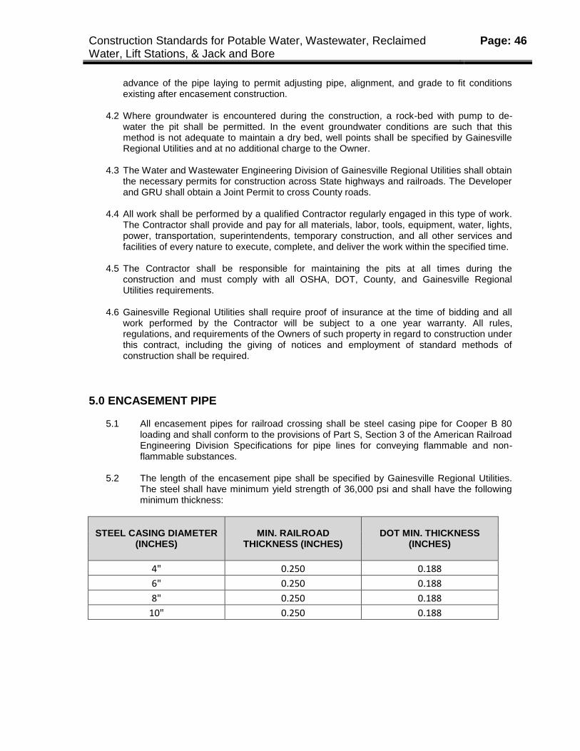
Construction Standards for Potable Water, Wastewater, Reclaimed Water, Lift Stations, & Jack and Bore
Page: 46
advance of the pipe laying to permit adjusting pipe, alignment, and grade to fit conditions existing after encasement construction.
4.2 Where groundwater is encountered during the construction, a rock-bed with pump to de-
water the pit shall be permitted. In the event groundwater conditions are such that this method is not adequate to maintain a dry bed, well points shall be specified by Gainesville Regional Utilities and at no additional charge to the Owner.
4.3 The Water and Wastewater Engineering Division of Gainesville Regional Utilities shall obtain
the necessary permits for construction across State highways and railroads. The Developer and GRU shall obtain a Joint Permit to cross County roads.
4.4 All work shall be performed by a qualified Contractor regularly engaged in this type of work.
The Contractor shall provide and pay for all materials, labor, tools, equipment, water, lights, power, transportation, superintendents, temporary construction, and all other services and facilities of every nature to execute, complete, and deliver the work within the specified time.
4.5 The Contractor shall be responsible for maintaining the pits at all times during the
construction and must comply with all OSHA, DOT, County, and Gainesville Regional Utilities requirements.
4.6 Gainesville Regional Utilities shall require proof of insurance at the time of bidding and all
work performed by the Contractor will be subject to a one year warranty. All rules, regulations, and requirements of the Owners of such property in regard to construction under this contract, including the giving of notices and employment of standard methods of construction shall be required.
5.0 ENCASEMENT PIPE
5.1 All encasement pipes for railroad crossing shall be steel casing pipe for Cooper B 80 loading and shall conform to the provisions of Part S, Section 3 of the American Railroad Engineering Division Specifications for pipe lines for conveying flammable and non-flammable substances.
5.2 The length of the encasement pipe shall be specified by Gainesville Regional Utilities.
The steel shall have minimum yield strength of 36,000 psi and shall have the following minimum thickness:
STEEL CASING DIAMETER (INCHES)
MIN. RAILROAD THICKNESS (INCHES)
DOT MIN. THICKNESS (INCHES)
4" 0.250 0.188
6" 0.250 0.188
8" 0.250 0.188
10" 0.250 0.188
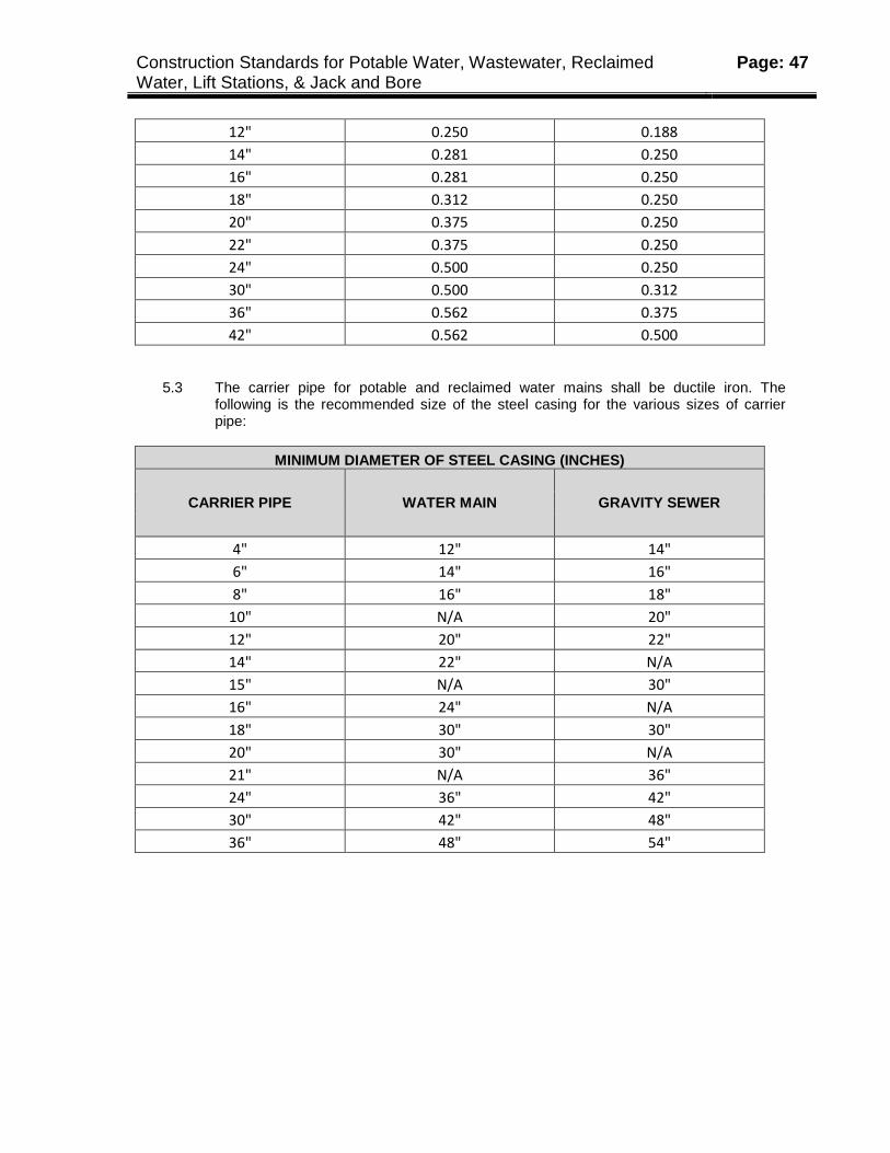
Construction Standards for Potable Water, Wastewater, Reclaimed Water, Lift Stations, & Jack and Bore
Page: 47
12" 0.250 0.188
14" 0.281 0.250
16" 0.281 0.250
18" 0.312 0.250
20" 0.375 0.250
22" 0.375 0.250
24" 0.500 0.250
30" 0.500 0.312
36" 0.562 0.375
42" 0.562 0.500
5.3 The carrier pipe for potable and reclaimed water mains shall be ductile iron. The
following is the recommended size of the steel casing for the various sizes of carrier pipe:
MINIMUM DIAMETER OF STEEL CASING (INCHES)
CARRIER PIPE WATER MAIN GRAVITY SEWER
4" 12" 14"
6" 14" 16"
8" 16" 18"
10" N/A 20"
12" 20" 22"
14" 22" N/A
15" N/A 30"
16" 24" N/A
18" 30" 30"
20" 30" N/A
21" N/A 36"
24" 36" 42"
30" 42" 48"
36" 48" 54"
Construction Standards for Potable Water, Wastewater, Reclaimed Water, Lift Stations, & Jack and Bore
Page: 48
6.0 BORING AND JACKING METHOD
6.1 When shown on the Drawing(s) for the encasement pipe to be installed by boring and jacking method, the following shall apply:
6.2 Prior to a casing installation by the boring and jacking method, the roadway or rail-bed shall
be inspected for depressions or pavement damage. Gainesville Regional Utilities shall be notified and the Developer’s Engineer will prepare a profile along the centerline of the proposed pipe line and shall advise the governing agency controlling the right-of-way.
6.3 All steel casing material, welding equipment, boring and jacking equipment, flood lights, and
all emergency equipment shall be on the site and in first class working condition before the casing installation will be permitted. Depending on field conditions, the face of the rail-bed or roadbed may be required to be sheeted to prevent all earth movement.
6.4 Under no circumstances may anchors or other supports be installed in the roadbed or rail-
bed. The work shall not begin until Gainesville Regional Utilities approval has been obtained; once started the operation shall continue without interruption until the crossing is completed.
6.5 The maximum permissible encasement pipe variation from the alignment and grade shown
on the Drawing(s) shall be as follows: 6.6 Water Mains & Force Mains
1) For alignment - l.0 feet
2) For grade - O.5 percent greater and no percent less than shown on the Plans. 6.7 Gravity Sewer Mains
1) Line and grade to comply with the construction Drawing(s).
2) The Contractor shall use the elevations and bench marks as shown on the Drawing(s). 6.8 Where cover conditions are critical or where the encasement is to be constructed in close
proximity to other underground utilities, Gainesville Regional Utilities may direct that, before the casing pipe is installed, a small temporary guide pipe be jacked across the roadbed along the centerline location of the casing pipe.
7.0 COMPLETION AND CLEAN-UP
7.1 After the installation, the steel casing pipe shall be cleaned free of debris, soil and other foreign matter. The carrier pipe shall be installed and the ends of the casing plugged with a brick and masonry seal, or as specified by Gainesville Regional Utilities.
7.2 The Contractor shall be held responsible for repair of any settling occurring over
encasement installed under this Contract and within the period of the General Guarantee. Such repair work shall be at no additional cost to Gainesville Regional Utilities.

Construction Standards for Potable Water, Wastewater, Reclaimed Water, Lift Stations, & Jack and Bore
Page: 49
7.3 The Contractor shall be responsible for all work, including backfilling, seeding, sodding,
mulching, and complete clean-up of the construction area as required by the Federal Government, State, County, Railroad Company, or Gainesville Regional Utilities.
8.0 PAVING, CURB, GUTTER AND WALKWAY WORK
8.1 When construction of pipe beneath paving is permitted, the pavement, and any curb and gutter, driveway, or walkway shall be removed to neat lines of a sufficient width to allow proper installation of the pipe work.
8.2 Signal lights, warning signs, and barricades shall be installed and maintained as required
for adequate safety. 8.3 No pavement base shall be replaced before the ditch backfill has been inspected and
approved. Density and compaction tests may be required by the authority having jurisdiction over the street, road, or highway involved.
8.4 The pavement shall be replaced in accordance with the "Florida Department of
Transportation, Standard Specifications for Road and Bridge Construction”, latest edition. 8.5 Curb and gutter shall be replaced with a new concrete unit poured-in-place and having the
same cross section as the original curb removed. The concrete shall be thoroughly cured. Backfill under concrete work shall be thoroughly compacted and the sub-grade approved before any concrete may be poured.
8.6 Concrete walks and driveways shall be replaced with concrete of the same cross section as
the original walk or driveway. The concrete shall be thoroughly cured. Backfill under concrete work shall be thoroughly compacted and the sub-grade approved before any concrete may be poured.
9.0 CASING SPACERS
9.1 Carrier pipe shall be supported on stainless steel supports. Two (2) supports per joint of ductile iron pipe shall be used located two (2) feet from each end of the pipe. Three (3) supports per joint of PVC pipe shall be used, located at the center and two (2) feet from each end of the pipe.
9.2 Spacers shall be bolt on style with a two piece solid shell made from T-304 stainless steel
of a minimum 14 gauge thickness. The shell shall be lined with a ribbed P.V.C. sheet of a 0.090" thickness that overlaps the edges.
9.3 Runners, made from UHMW polymer, shall be attached to risers at appropriate positions to
properly locate the carrier pipe within the casing and to ease installation.

Construction Standards for Potable Water, Wastewater, Reclaimed Water, Lift Stations, & Jack and Bore
Page: 50
9.4 Risers shall be made from T-304 stainless steel of a minimum 14 gauge thickness and shall
be attached to the shell by MIG welding. All welds shall be fully passivated. All fasteners shall be made from T-304 stainless steel.
9.5 Riser and runner height, and the number of runners per support shall be as follows:
Four (4) Runners, height 2.0" through 12" carrier pipe
Six (6) Runners, height 2.5” through 36” carrier pipe
Seven (7) Runners, height 2.5” through 48” carrier pipe 9.6 Casing spacers shall be Model CCS as manufactured by Cascade Waterworks Mfg. Co. of
Yorkville, IL, PSI (Pipeline Seal and Insulator_, Inc. of Houston TX, or GRU approved equal.