Embed Size (px)
Citation preview
Gaia
GAIA.ASU.SP.ESM.00004Issue 1
Page 1 of 125
Document Autogenerated from DOORS Module : /GAIA Prime/Level 4/4_12 CDMU RS/Gaia- CDMU GAIA_ASU_SP_ESM_00004_01.doc
GAIA CDMU Requirement Specification
CI CODE: 13100 DRL Refs :
UK EXPORT CONTROL RATING : 9E001, 9E002
Rated By : D.Perkins
Prepared by: Date:
Checked by: Date:
Approved by: Date:
Authorised by: Date:
This document is produced under ESA contract, ESA export exemptions may therefore apply. These Technologies may require an export licence if exported from the EU
© EADS Astrium Limited 2006
EADS Astrium Ltd owns the copyright of this document which is supplied in confidence and which shall not be used for any purpose other than that for which it is supplied and shall not in whole or in part be reproduced, copied, or
communicated to any person without written permission from the owner.
EADS Astrium Limited, Registered in England and Wales No. 2449259 Registered Office: Gunnels Wood Road, Stevenage, Hertfordshire, SG1 2AS, England
Gaia
GAIA.ASU.SP.ESM.00004Issue 1
Page 2 of 125
EADS Astrium Ltd owns the copyright of this document which is supplied in confidence and which shall not be used for any purpose other than that for which it is supplied and shall not in whole or in part be reproduced, copied, or communicated to any person without written permission from the owner.
GAIA_ASU_SP_ESM_00004_01.doc
INTENTIONALLY BLANK
Gaia
GAIA.ASU.SP.ESM.00004Issue 1
Page 3 of 125
EADS Astrium Ltd owns the copyright of this document which is supplied in confidence and which shall not be used for any purpose other than that for which it is supplied and shall not in whole or in part be reproduced, copied, or communicated to any person without written permission from the owner.
GAIA_ASU_SP_ESM_00004_01.doc
CONTENTS 1 Introduction and Scope ............................................................................................................................. 5
1.1 Introduction ........................................................................................................................................ 5 1.2 Scope ................................................................................................................................................. 6 1.3 Summary Description......................................................................................................................... 6
2 Documents ................................................................................................................................................ 8 2.1 Applicable Documents ....................................................................................................................... 8 2.2 Reference Documents ....................................................................................................................... 8
3 CDMU Functional and Performance Requirements.................................................................................. 9 3.1 CDMU Definition ................................................................................................................................ 9 3.2 Functions and Performance............................................................................................................. 12
3.2.1 General ..................................................................................................................................... 12 3.2.2 DC/DC Converter...................................................................................................................... 13 3.2.3 Transponder Interface Function................................................................................................ 13 3.2.4 Processor Module ..................................................................................................................... 22 3.2.5 Reconfiguration Unit ................................................................................................................. 28 3.2.6 Mass Memory Unit (MMU)........................................................................................................ 34 3.2.7 On-Board Time Synchronisation, Distribution and Timing Services......................................... 36
3.3 CDMU Modes................................................................................................................................... 40 3.3.1 General ..................................................................................................................................... 40 3.3.2 Off Mode ................................................................................................................................... 40 3.3.3 Power Up Mode ........................................................................................................................ 40 3.3.4 Reset / Init Mode....................................................................................................................... 41 3.3.5 Nominal Mode........................................................................................................................... 41 3.3.6 Service Mode ............................................................................................................................ 41 3.3.7 Error Mode ................................................................................................................................ 42
3.4 Electrical Design and Interface Requirements................................................................................. 44 3.4.1 Primary Power Interface and Power Consumption................................................................... 44 3.4.2 Transponder Interface Function (TIF)....................................................................................... 46 3.4.3 Command, Monitoring, Data Transfer and Synchronisation Interfaces.................................... 47 3.4.4 Spacewire Test Interface .......................................................................................................... 53
3.5 CDMU Software Requirements........................................................................................................ 53 3.5.1 Start-Up Software (SUSW) ....................................................................................................... 53 3.5.2 Application Programs Interface Package (API Package) ......................................................... 61 3.5.3 Acceptance Test Software........................................................................................................ 63 3.5.4 Development Requirements ..................................................................................................... 64 3.5.5 On Board SW Design Requirements ........................................................................................ 65 3.5.6 Hardware/ Software Interfaces ................................................................................................. 66
3.6 CDMU Operational Requirements ................................................................................................... 67 3.6.1 Observability Requirements...................................................................................................... 67 3.6.2 Commandability Requirements................................................................................................. 68
3.7 Failure Detection, Isolation and Recovery (FDIR) Requirements.................................................... 69 4 CDMU Specific Design and Interface Requirements .............................................................................. 71
4.1 Mechanical Design and Interface Requirements ............................................................................. 71 4.1.1 Mass.......................................................................................................................................... 71 4.1.2 Centre of Gravity....................................................................................................................... 71 4.1.3 Envelope ................................................................................................................................... 71
4.2 Thermal Design and Interface Requirements .................................................................................. 71 4.2.1 Heat Dissipation........................................................................................................................ 71 4.2.2 CDMU Thermal Properties........................................................................................................ 71 4.2.3 Temperature Limits ................................................................................................................... 72
4.3 CDMU Specific Electrical Design and Interface Requirements ....................................................... 72 4.3.1 CDMU Specific Electrical Interface Requirements ................................................................... 72 4.3.2 CDMU EGSE/ Checkout Electrical Interface Requirements..................................................... 75
5 General Design and Interface Requirements.......................................................................................... 77 5.1 GDIR Applicability ............................................................................................................................ 77
Gaia
GAIA.ASU.SP.ESM.00004Issue 1
Page 4 of 125
EADS Astrium Ltd owns the copyright of this document which is supplied in confidence and which shall not be used for any purpose other than that for which it is supplied and shall not in whole or in part be reproduced, copied, or communicated to any person without written permission from the owner.
GAIA_ASU_SP_ESM_00004_01.doc
5.2 CDMU RAM Specific Requirements ................................................................................................ 77 5.2.1 Reliability................................................................................................................................... 77 5.2.2 Availability ................................................................................................................................. 77 5.2.3 Maintainability ........................................................................................................................... 77 5.2.4 CDMU Fault Tolerance Requirements...................................................................................... 77
5.3 Design Rules.................................................................................................................................... 79 5.4 Identification & Marking.................................................................................................................... 79 5.5 Unit Packing ..................................................................................................................................... 79 5.6 Handling ........................................................................................................................................... 79 5.7 Mass................................................................................................................................................. 79 5.8 COG/M.I. .......................................................................................................................................... 79
6 Product Assurance Requirements........................................................................................................... 80 7 VERIFICATION REQUIREMENTS ......................................................................................................... 81
7.1 Required CDMU Level Tests ........................................................................................................... 81 7.1.1 Functional/ Performance Tests................................................................................................. 81
8 GDIR Applicability Matrix......................................................................................................................... 82 9 Annex I: CDMU external I/O Interface Summary .................................................................................. 115 10 Annex II: Typical CDMU external ON/OFF (SHP) Allocation (TBC).................................................. 116 11 Annex III: Simulation Model Data Requirements............................................................................... 117 12 Abbreviations List .............................................................................................................................. 118
TABLES Table 1- Applicable Documents........................................................................................................................ 8 Table 2 - Reference Documents....................................................................................................................... 8
FIGURES Figure 1.1-1: Gaia Satellite Configuration ....................................................................................................... 5 Figure 1.3-1: CDMU Functional Overview....................................................................................................... 7 Figure 3.2-1: TC/TM Data Flow and Cross-Strapping Principle.................................................................... 14
Gaia
GAIA.ASU.SP.ESM.00004Issue 1
Page 5 of 125
EADS Astrium Ltd owns the copyright of this document which is supplied in confidence and which shall not be used for any purpose other than that for which it is supplied and shall not in whole or in part be reproduced, copied, or communicated to any person without written permission from the owner.
GAIA_ASU_SP_ESM_00004_01.doc
1 INTRODUCTION AND SCOPE
1.1 Introduction
This document specifies the requirements for the Control and Data Management Unit (CDMU) which is installed on the Gaia satellite.
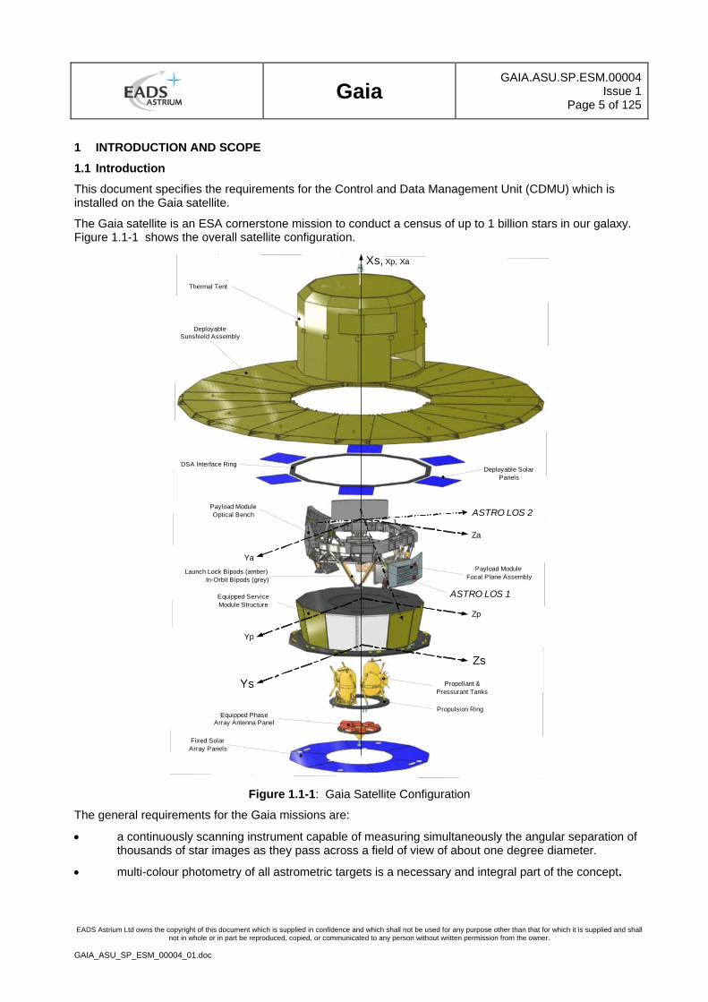
The Gaia satellite is an ESA cornerstone mission to conduct a census of up to 1 billion stars in our galaxy. Figure 1.1-1 shows the overall satellite configuration.
Xs, Xp, Xa
ASTRO LOS 2
ASTRO LOS 1
Za
Zs
Zp
Yp
Ya
Ys
Fixed SolarArray Panels
Equipped PhaseArray Antenna Panel
Propulsion Ring
Propellant &Pressurant Tanks
Equipped ServiceModule Structure
Payload ModuleOptical Bench
Payload ModuleFocal Plane Assembly
Deployable SolarPanels
DSA Interface Ring
DeployableSunshield Assembly
Thermal Tent
Launch Lock Bipods (amber)In-Orbit Bipods (grey)
Figure 1.1-1: Gaia Satellite Configuration
The general requirements for the Gaia missions are:
• a continuously scanning instrument capable of measuring simultaneously the angular separation of thousands of star images as they pass across a field of view of about one degree diameter.
• multi-colour photometry of all astrometric targets is a necessary and integral part of the concept.
Gaia
GAIA.ASU.SP.ESM.00004Issue 1
Page 6 of 125
EADS Astrium Ltd owns the copyright of this document which is supplied in confidence and which shall not be used for any purpose other than that for which it is supplied and shall not in whole or in part be reproduced, copied, or communicated to any person without written permission from the owner.
GAIA_ASU_SP_ESM_00004_01.doc
• The whole sky is systematically scanned in such a manner that observations extending over several years permit a complete separation of the astrometric parameters describing the motions and distances of the stars.
The GAIA mission will rely on the proven principles of ESA's Hipparcos mission to solve one of the most difficult yet deeply fundamental challenges in modern astronomy: to create an extraordinarily precise three-dimensional map of about one billion stars throughout our Galaxy and beyond. In the process, it will map their motions, which encode the origin and subsequent evolution of the Galaxy. Through comprehensive photometric classification, it will provide the detailed physical properties of each star observed: characterizing their luminosity, temperature, gravity, and elemental composition. This massive stellar census will provide the basic observational data to tackle an enormous range of important problems related to the origin, structure, and evolutionary history of our Galaxy.
1.2 Scope
The document comprises the contractually relevant technical requirements and constraints for the Gaia CDMU. This includes:
• the performance as well as design and interface requirements of the CDMU hardware and its basic software (BSW)
• the testing and verification requirements
• the product assurance requirements
Note: the application software is not part of this specification.
Requirements within this document are shown in an italic font. Each requirement is proceeded by a summary line that contains the following fields, delimited by "/".
· <Doors Requirement Number>CDMU-xyz. This is a unique number, assigned consecutively
· <Created From> Shows parent requirement
· <Test Method> T= Test, A = Analysis, I = Inspection, R = Review of Design, D = Definition
Unless specifically agreed otherwise,
For verification R, documentation presented shall enable the specific requirement to be reviewed
For verification A, the Analysis presented shall be in a delivered form (summary or detailed can be agreed)
If tables are considered as part of a requirement they are referenced clearly in the text and inserted after and separated from the requirement table and are managed as free text attached to the identifier requirement.
The trace to the upper level requirements (Upper Links), shall be managed using the following format:
· AAA-NNNN where AAA is a label associated to the upper document and NNNN the requirement identifier of this upper level.
· Or CREATED key word if the requirement has no link with upper level
All elements of the document, which are not presented in the format explained above are not requirements and will not be verified or tracked.
1.3 Summary Description
The Gaia Control and Data Management Unit (CDMU) is the central control unit for all onboard data handling activities, attitude and orbit control system (AOCS), the management of the Service Module (SVM) and the management of the Payload Module (PLM).
Data handling functions mainly consist of command distribution, telemetry acquisition and timing facilities during all phases of the mission. The CDMU architecture is based on a dual redundant Mil-1553 bus Command/Monitoring bus with SpaceWire bus interface for the PDHU, RTS and EGSE. The CDMU-EIU
Gaia
GAIA.ASU.SP.ESM.00004Issue 1
Page 7 of 125
EADS Astrium Ltd owns the copyright of this document which is supplied in confidence and which shall not be used for any purpose other than that for which it is supplied and shall not in whole or in part be reproduced, copied, or communicated to any person without written permission from the owner.
GAIA_ASU_SP_ESM_00004_01.doc
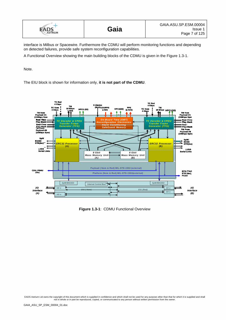
interface is Milbus or Spacewire. Furthermore the CDMU will perform monitoring functions and depending on detected failures, provide safe system reconfiguration capabilities.
A Functional Overview showing the main building blocks of the CDMU is given in the Figure 1.3-1.
Note.
The EIU block is shown for information only, it is not part of the CDMU.
On-Board Time (OBT)Reconfiguration Electronics
Alarm ConditioningSafeGuard Memory
ERC32 Processor(A)
ERC32 Processor(B)
TMX-Band5 Mbps
TCX-Band2 KbpsTM From
Payload #B(10Mbps Spw)
TCX-Band2 Kbps
HPC1
TC DecoderTransfer FrameGenerator (TFG)
TC Decoder & CPDUTransfer FrameGenerator (TFG)
… ……
Real -TimePlay -BackReal -TimePlay -Back
Real -TimePlay -BackReal -
- Back
…
8 Alarms (BLD) CDUPPS
LVDS HPC2(32)
On-Board Time (OBT)Reconfiguration Electronics
Alarm ConditioningSafeGuard Memory
ERC32 Processor(A)
ERC32 Processor(B)
Platform (Nom & Red) MIL-STD-1553(external)
TM10 Mbps
LVDSTC Nom4 Kbps
TM fromPayload #A
(10M bps Spw
TC Nom4 Kbps
HPC1 (32)
Payload ( Nom & Red) MIL-STD-1553 (external)
SpWEGSE/STR(tbc)…
LVDSSerial Links
…
SpW /EGSESTR(tbc)
…
LVDS Serial Links
…
8 GbitMass Memory Unit
(A)
8 GbitMass Memory Unit
(B)
TC Decoder & CPDUTransfer FrameGenerator (TFG)
TC Decoder & CPDUTransfer FrameGenerator (TFG)
…
HPC1(32)
……
TM10 M bps
Real -TimePlay -BackReal -Time
-
-Play -Back
-Play -Back
…
PPS (LVDS)
EIU ( Nom) EIU (Red)
TM FromPayload #B
(10Mbps Spw)
TM fromPayload #A
(10Mbps Spw
CDU, PDHUFPA
EPS,TT&CSTR (tbc), PCDU
I/O 1
I/O n
I/O 1
I/O n
I/O Interface
(A)
I/OInterface
(B)
SpW /Mil1553 SpW /Mil1553Internal Control Bus
TC Red4 Kbps TC Red
4 Kbps
On-Board Time (OBT)Reconfiguration Electronics
Alarm ConditioningSafeGuard Memory
ERC32 Processor(A)
ERC32 Processor(B)
TMX-Band5 Mbps
TCX-Band2 KbpsTM From
Payload #B(10Mbps Spw)
TCX-Band2 Kbps
HPC1
TC DecoderTransfer FrameGenerator (TFG)
TC Decoder & CPDUTransfer FrameGenerator (TFG)
… ……
Real -TimePlay -BackReal -TimePlay -Back
Real -TimePlay -BackReal -
- Back
…
8 Alarms (BLD) CDUPPS
LVDS HPC2(32)
On-Board Time (OBT)Reconfiguration Electronics
Alarm ConditioningSafeGuard Memory
ERC32 Processor(A)
ERC32 Processor(B)
Platform (Nom & Red) MIL-STD-1553(external)
TM10 Mbps
LVDSTC Nom4 Kbps
TM fromPayload #A
(10M bps Spw
TC Nom4 Kbps
HPC1 (32)
Payload ( Nom & Red) MIL-STD-1553 (external)
SpWEGSE/STR(tbc)…
LVDSSerial Links
…
SpW /EGSESTR(tbc)
…
LVDS Serial Links
…
8 GbitMass Memory Unit
(A)
8 GbitMass Memory Unit
(B)
TC Decoder & CPDUTransfer FrameGenerator (TFG)
TC Decoder & CPDUTransfer FrameGenerator (TFG)
…
HPC1(32)
……
TM10 M bps
Real -TimePlay -BackReal -Time
-
-Play -Back
-Play -Back
…
PPS (LVDS)
EIU ( Nom) EIU (Red)
TM FromPayload #B
(10Mbps Spw)
TM fromPayload #A
(10Mbps Spw
CDU, PDHUFPA
EPS,TT&CSTR (tbc), PCDU
I/O 1
I/O n
I/O 1
I/O n
I/O Interface
(A)
I/OInterface
(B)
SpW /Mil1553 SpW /Mil1553Internal Control Bus
TC Red4 Kbps TC Red
4 Kbps
Figure 1.3-1: CDMU Functional Overview
Gaia
GAIA.ASU.SP.ESM.00004Issue 1
Page 8 of 125
EADS Astrium Ltd owns the copyright of this document which is supplied in confidence and which shall not be used for any purpose other than that for which it is supplied and shall not in whole or in part be reproduced, copied, or communicated to any person without written permission from the owner.
GAIA_ASU_SP_ESM_00004_01.doc
2 DOCUMENTS
2.1 Applicable Documents
The following publications form a part of this document to the extent specified herein. Unless an issue is quoted for a document, the current issue is deemed to apply. When an issue is quoted, that issue and no other must be used.
[AD 1] ESCC-E-70-41A Ground Systems and Operations- TM/TC PUS
[AD 2] GAIA.ASF.SP.SAT.0002 General Design and Interface Requirements Specification (GDIR)
[AD 3] GAIA.ASF.SP.SAT.00029 Software PA Requirements for Subcontractors
[AD 4] GAIA.ESC.ICD.00516 GAIA Space Ground Interface Control Document(SGICD)
Vol 2 Generic Packet Structure
[AD 5] GAIA.ASF.SP.SAT.00059 Gaia Mil-1553 Data Bus Protocol Specification
[AD 6] GAIA.ESC.ICD.00515 GAIA Space Ground Interface Control Document (SGICD) Vol 1 RF Interface
[AD 7] Deleted
[AD 8] GAIA.ASF.SP.SAT.00004 Product Assurance Requirement for Sub Contractor
[AD 9]
GAIA.ASF.TCN.CSW.00019 GAIA Non-Volatile Memory Protection (System Requirements for Gaia EEPROM use.
[AD10] GAIA.ASD.SP.SAT.00006 CAD Data Exchange Requirement [AD11] GAIA.ASD.SP.SAT.00007 Finite Element Modelling Requirement [AD12] GAIA.ASD.SP.SAT.00008 Thermal Modelling Requirement
Table 1- Applicable Documents
2.2 Reference Documents
[RD 1] TIA/EIA-646-A Low Voltage Differential Signalling Specification
Table 2 - Reference Documents
Gaia
GAIA.ASU.SP.ESM.00004Issue 1
Page 9 of 125
EADS Astrium Ltd owns the copyright of this document which is supplied in confidence and which shall not be used for any purpose other than that for which it is supplied and shall not in whole or in part be reproduced, copied, or communicated to any person without written permission from the owner.
GAIA_ASU_SP_ESM_00004_01.doc
3 CDMU FUNCTIONAL AND PERFORMANCE REQUIREMENTS
3.1 CDMU Definition
CDMU-130/ERS_438/T,R
The CDMU shall comprise two functional branches operating in redundancy.
CDMU-131/ERS_45,ERS_900/T,R
Each of the redundant branches shall provide the following functional elements/ services/ interfaces:
ERC 32 Processor Module (Processor Module) including:
• Processing modules and basic software (BSW)
• On-board time generation, synchronisation, distribution and services of the SCET
• MIL-STD-1553B bus services
• TT&C interface functions (TIF) including:
TC reception function & Decoder
Command Pulse Distribution Unit (CPDU)
TM Encoder & transmission function
• Mass Memory Unit (MMU)
• UART link for interfacing to units with RS422 interfaces
• Spacewire(SpW) link to payload science data transfers(PDHU) and other platform units with Spacewire I/F.
• Spacewire link to EGSE for test , simulation, debug purposes..
CDMU-132/ERS_438,ERS_900/T,A,R
The CDMU redundant functions shall be based on a cold redundancy scheme, except for the
• TC Decoder function
• Telemetry function
• System Mass Memory
• Safe Guard Memory (SGM)
• Reconfiguration Unit
• Spacecraft Elapsed Timer (SCET) Time Distribution
• DC/DC Converters associated with hot redundant functions
which shall be operated in hot redundancy.
CDMU-134/ERS_45,ERS_823/T,A,R
The CDMU shall receive Telecommands from ground via digital TC I/Fs or via the EGSE TC interface.
CDMU-135/ERS_45/T,R
The CDMU shall validate and disassemble the Command Link Transmission Units (CLTUs) and TC Transfer Frames.
CDMU-136/ERS_872/T,R
The CDMU shall distribute TC Segments according to the Multiplexed Access Point Identifier.
Gaia
GAIA.ASU.SP.ESM.00004Issue 1
Page 10 of 125
EADS Astrium Ltd owns the copyright of this document which is supplied in confidence and which shall not be used for any purpose other than that for which it is supplied and shall not in whole or in part be reproduced, copied, or communicated to any person without written permission from the owner.
GAIA_ASU_SP_ESM_00004_01.doc
CDMU-137/CREATED/T,R
It shall be possible to send commands to the Mil-Std_1553 Data bus without modification by the CDMU.
CDMU-138/ERS_448,ERS_451/T,R
The CDMU shall acquire TM data via the Mil-Std 1553 B Data Bus from
• SVM
• PLM
CDMU-140/ERS_455/R
The CDMU shall provide Space Wire Interfaces with the Payload Module.
CDMU-141/ERS_844/T,A
The Mass Memory unit speed shall be compliant with the SVM and PLM data rate.
CDMU-142/ERS_815/T,A
The CDMU shall control the TM bandwidth occupation of the different TM sources.
CDMU-143/CREATED/T,A
The CDMU shall insert TM Source Packets in TM Transfer Frames.
CDMU-144/CREATED/T,A
The CDMU shall expand TM Transfer Frames to Channel Access Data Units.
CDMU-145/CREATED/T,R
The CDMU shall contain the Oscillator and provide and maintain the SCET in CUC format.
CDMU-146/ERS_804/T,A,R
The CDMU time function shall either operate in the free-running when the CDU PPS is not available or shall synchronise to the CDU PPS Atomic Clock when commanded.
CDMU-147/CREATED/T,A
The CDMU shall provide environment and sufficient processing/ memory resources in accordance with ESA margin policy.
CDMU-3452//T,A
The CDMU shall support storage of time-tag commands and execution of time-tag commands when the time-tag is achieved in conjunction with software.
CDMU-149/CREATED/T,A
The CDMU shall support the storage of essential housekeeping telemetry data and autonomously taken actions in the Safeguard Memory without software intervention.
CDMU-150/CREATED/T,A
The CDMU shall support storage of telemetry data and measurement data in the CDMU Mass Memory.
CDMU-151/CREATED/T,A
The CDMU shall support dump of measurement data or telemetry data stored in the CDMU Mass Memory.
CDMU-152/CREATED/T,A
The CDMU shall support memory dumps and patches of the CDMU memories and all external memories on request from ground.
Gaia
GAIA.ASU.SP.ESM.00004Issue 1
Page 11 of 125
EADS Astrium Ltd owns the copyright of this document which is supplied in confidence and which shall not be used for any purpose other than that for which it is supplied and shall not in whole or in part be reproduced, copied, or communicated to any person without written permission from the owner.
GAIA_ASU_SP_ESM_00004_01.doc
CDMU-153/CREATED/T,A
The CDMU shall recover autonomously its operability by reconfiguration of the operational modules in case of detection of any anomaly inside the CDMU.
CDMU-154/CREATED/T,R
In support of an end-to-end test capability, the CDMU shall allow in parallel to its operation in nominal configuration the acquisition of data from redundant units which are not part of the nominal configuration via its I/O interfaces .
CDMU-156/ERS_45/T,R
The CDMU shall contain cold redundant processing modules including memory resources and MIL-STD-1553B Bus Controller (BC) functions.
CDMU-3438/ERS_45/T,R
The processor module ON/OFF control shall be implemented by use of a combination of one or more of
• HPC-type 1 from the Command Decoder or
• HPC-type 2 from the Reconfiguration Unit
• HPC-type 3 under the software control
CDMU-2096/ERS_45/A,R
The CDMU shall contain redundant Spacewire Interface functions.
The Spacewire Interface module shall comprise
• PLM - PDHU interface
• E-SVM -EIU interface
• EGSE test/debug
• spare for E-SVM units (TBC)
CDMU-157/ERS_438/T,A,R
The CDMU shall contain hot redundant, i.e., not ON/OFF switchable Telecommand (TC) Module.
CDMU-158/ERS_45,ERS_831/A,R
Each TC Module shall comprise the
• Digital TC signal interface (from TT&C)
• EGSE TC I/F
• Packet Telecommand Decoder
• Command Pulse Distribution Unit (CPDU)
• Output I/F to each Processor Module (Processor Module)
CDMU-159/ERS_438,ERS_462,/T,R
The CDMU shall hot redundant Telemetry (TM) Module.
Its selection shall be implemented by use of
• HPC-type 1 from the CPDU of the Command Decoder or
• HPC-type 2 from the Reconfiguration Unit
Gaia
GAIA.ASU.SP.ESM.00004Issue 1
Page 12 of 125
EADS Astrium Ltd owns the copyright of this document which is supplied in confidence and which shall not be used for any purpose other than that for which it is supplied and shall not in whole or in part be reproduced, copied, or communicated to any person without written permission from the owner.
GAIA_ASU_SP_ESM_00004_01.doc
CDMU-160/ERS_45/R
Each TM Module shall comprise the following functions:
• Transfer Frame Generator (TFG),
• TM Encoder (RS Encoding, Convolutional Coding, Pseudo Randomisation),
• EGSE TM interface (including EGSE TM Signal and TM Clock)
• Input I/F's from both Processor Modules
• Clock/Data output I/F to the TT&C.
• Input to Virtual Channel(VC) from Processor Module
• Input to Virtual Channel from the PLM
CDMU-161/ERS_438/T,R
The CDMU shall contain a Reconfiguration Module (RM) with memory resources and shall operate in hot redundancy.
CDMU-162/ERS_438/T,R
The CDMU shall contain two Mass Memory Units (MMU) that shall operate in hot redundancy.
CDMU-163/ERS_45/T,R
The CDMU shall contain two SCET's, with Clock Distribution, Synchronisation functions and shall operate in hot redundancy.
CDMU-166/CREATED/A,R
The CDMU shall contain Basic Software (BSW) including:
• Start-Up SW (bootstrap, built-in-test and initialisation)
• Application Program Interface (API) SW package
• Service Mode SW
3.2 Functions and Performance
3.2.1 General
CDMU-169/ERS_450/T,R
Both Processor Modules, nominal and redundant, shall be cross-strapped to the nominal MIL-STD-1553B Bus and the redundant MIL-STD-1553B Bus ( PLM and SVM).
CDMU-170/CREATED/T,A,R
It shall be possible to reset, enable, disable and overwrite functions which can be automatically activated. In the case of automatic functions without this capability details shall be provided to Prime and ESA for approval.
CDMU-171/ERS_45/T,R
The CDMU shall include the resources from which the timing for all signals of the required serial data links (Mil-Bus, Spacewire), the TM I/Fs, the EGSE TM I/Fs, the central Spacecraft Elapsed Timer(SCET) and the Scheduler for SW support shall be derived.
CDMU-172/CREATED/I,R
A pair of redundant thermistor shall be mounted on the master oscillator housing (Processor Module) for housekeeping acquisition of the temperature environment.
Gaia
GAIA.ASU.SP.ESM.00004Issue 1
Page 13 of 125
EADS Astrium Ltd owns the copyright of this document which is supplied in confidence and which shall not be used for any purpose other than that for which it is supplied and shall not in whole or in part be reproduced, copied, or communicated to any person without written permission from the owner.
GAIA_ASU_SP_ESM_00004_01.doc
3.2.2 DC/DC Converter
CDMU-174/CREATED/T,R
The CDMU switch-on and switch-off primary voltage thresholds and timing shall be defined and agreed via the ICD.
CDMU-175/CREATED/A,R
The CDMU shall generate all secondary power supplies required internally by the CDMU modules.
CDMU-176/CREATED/T,R
The following functions shall be permanently available, i.e not ON/OFF switchable:
• TC Decoder including the CPDU
• TM Module (TM)
• Reconfiguration Module (RM)
• Spacecraft Elapsed Timer (SCET)
• Safeguard Memory (SGM)
CDMU-177/CREATED/T,R
The following functions shall be available on command:
• Processor Module (PM)
• Mass Memory Unit (MMU)
• Spacewire Interface(SpW)
CDMU-178/CREATED/T,R
Functions within the CDMU that are switchable shall be controlled by commands released either by the TC Module (HPC-type 1), or the Reconfiguration Module (HPC-type 2) or by the Application Software (HPC-type 3).
CDMU-179/CREATED/T,A,R
It shall also be possible to control the setting of the ON/OFF switchable functions by HPC-type 1 commands.
CDMU-2099/CREATED/T,A
It shall be possible to switch on either processor module, while the other module is active, into the Service mode.
3.2.3 Transponder Interface Function
3.2.3.1 General
CDMU-182/ERS_465/A,R
The Transponder Interface (TIF) shall provide the following functions/ interfaces :
• Telecommand (TC) Reception function and Decoding interface with two X-Band Transponder Receivers and interfaces to Electrical Ground Support Equipment (EGSE)
• Direct TC (HPC-type 1) generation and distribution function
• Telemetry (TM) Encoding function and Transmission interface with two X-band Transponder Transmitters and interfaces to EGSE
• Implementation of Telemetry Buffers
• Communication with the Processor Modules
Gaia
GAIA.ASU.SP.ESM.00004Issue 1
Page 14 of 125
EADS Astrium Ltd owns the copyright of this document which is supplied in confidence and which shall not be used for any purpose other than that for which it is supplied and shall not in whole or in part be reproduced, copied, or communicated to any person without written permission from the owner.
GAIA_ASU_SP_ESM_00004_01.doc
CDMU-183/CREATED/T,R
The TC Reception function and the Direct TC (HPC-type 1) generation function shall be two separate functions operated in hot redundancy.
CDMU-184/CREATED/A
No single failure in one TIF shall propagate to the other TIF.
CDMU-185/CREATED/T,A,R
No single failure in the TIF function shall propagate to both X-band Transponder Receivers.
CDMU-186/CREATED/T,A,R
No single failure shall lead to the loss of spacecraft commanding capability
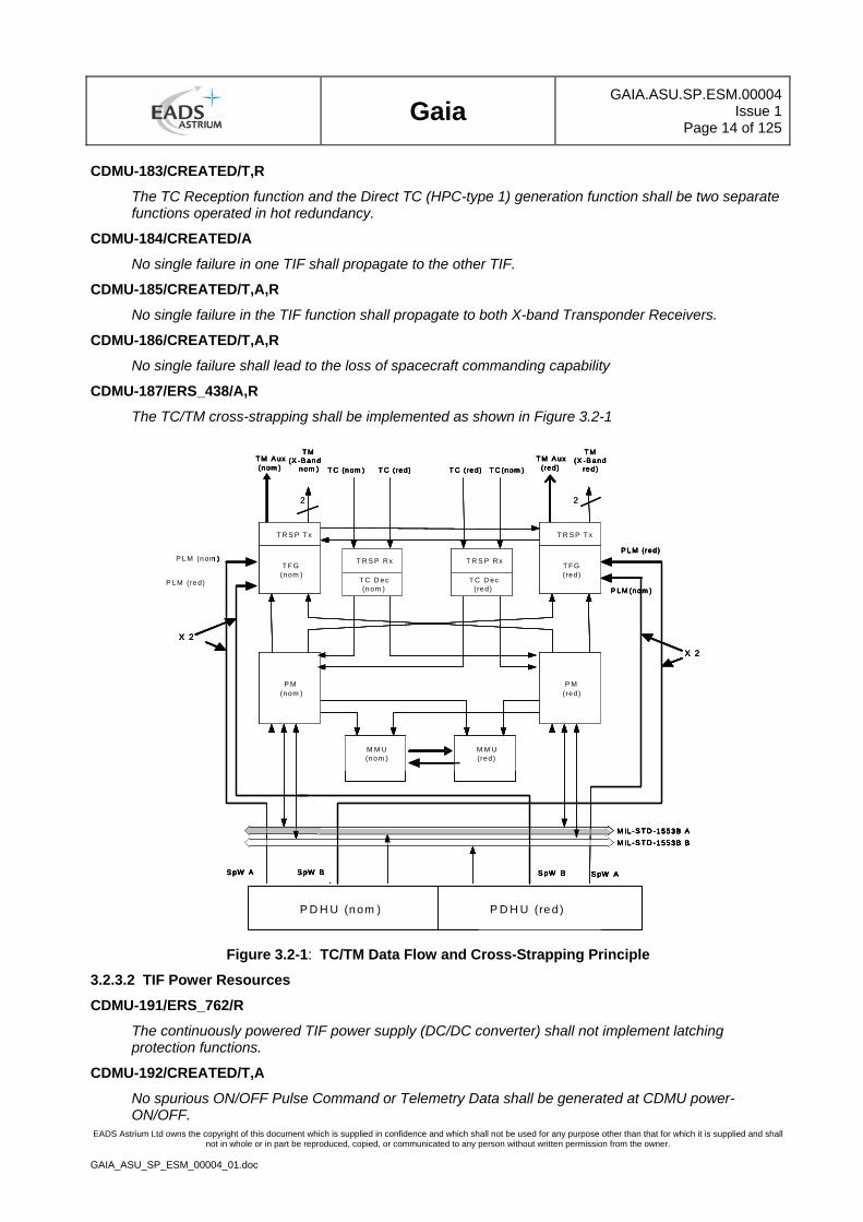
CDMU-187/ERS_438/A,R
The TC/TM cross-strapping shall be implemented as shown in Figure 3.2-1
T R S P T x
T FG(nom )
T FG(red)
T R S P Tx
P M(nom )
P M(red)
M M U(nom )
M M U(red)
M IL -S T D -1553B AM IL -S T D -1553B B
S pW A S pW B
A
S pW B S pW A
T M(X -B and
red )
T R S P R x
T C D ec(nom )
T R S P R x
T C D ec(red)
T M(X -B and
nom ) T C (nom ) T C (red)T C (red) T C (nom ) T M A ux(nom )
T M A ux(red)
P D H U (n om ) P D H U (re d )
P LM (nom )
P LM (red)
P LM (red)
P LM (nom )
X 2
X 2
22
T R S P T x
T FG(nom )
T FG(red)
T R S P Tx
P M(nom )
P M(red)
M M U(nom )
M M U(red)
M IL -S T D -1553B AM IL -S T D -1553B B
S pW A S pW B
A
S pW B S pW A
T M(X -B and
red )
T R S P R x
T C D ec(nom )
T R S P R x
T C D ec(red)
T M(X -B and
nom ) T C (nom ) T C (red)T C (red) T C (nom ) T M A ux(nom )
T M A ux(red)
P D H U (n om ) P D H U (re d )
P LM (nom )
P LM (red)
P LM (red)
P LM (nom )
X 2
X 2
T R S P T x
T FG(nom )
T FG(red)
T R S P Tx
P M(nom )
P M(red)
M M U(nom )
M M U(red)
M IL -S T D -1553B AM IL -S T D -1553B B
S pW A S pW B
A
S pW B S pW A
T M(X -B and
red )
T R S P R x
T C D ec(nom )
T R S P R x
T C D ec(red)
T M(X -B and
nom ) T C (nom ) T C (red)T C (red) T C (nom ) T M A ux(nom )
T M A ux(red)
P D H U (n om ) P D H U (re d )
P LM (nom )
P LM (red)
P LM (red)
P LM (nom )
T R S P T x
T FG(nom )
T FG(red)
T R S P Tx
P M(nom )
P M(red)
M M U(nom )
M M U(red)
M IL -S T D -1553B AM IL -S T D -1553B B
S pW A S pW B
A
S pW B S pW A
T R S P T x
T FG(nom )
T FG(red)
T R S P Tx
P M(nom )
P M(red)
M M U(nom )
M M U(red)
M IL -S T D -1553B AM IL -S T D -1553B B
S pW A S pW B
A
S pW B S pW A
T M(X -B and
red )
T R S P R x
T C D ec(nom )
T R S P R x
T C D ec(red)
T M(X -B and
nom ) T C (nom ) T C (red)T C (red) T C (nom ) T M A ux(nom )
T M A ux(red)
P D H U (n om ) P D H U (re d )
P LM (nom )
P LM (red)
P LM (red)
P LM (nom )
X 2
X 2
22
Figure 3.2-1: TC/TM Data Flow and Cross-Strapping Principle
3.2.3.2 TIF Power Resources
CDMU-191/ERS_762/R
The continuously powered TIF power supply (DC/DC converter) shall not implement latching protection functions.
CDMU-192/CREATED/T,A
No spurious ON/OFF Pulse Command or Telemetry Data shall be generated at CDMU power-ON/OFF.
Gaia
GAIA.ASU.SP.ESM.00004Issue 1
Page 15 of 125
EADS Astrium Ltd owns the copyright of this document which is supplied in confidence and which shall not be used for any purpose other than that for which it is supplied and shall not in whole or in part be reproduced, copied, or communicated to any person without written permission from the owner.
GAIA_ASU_SP_ESM_00004_01.doc
3.2.3.3 Telecommand Reception and Decoding
CDMU-194/ERS_451/T,A
The CDMU shall be able to receive and process a continuous uplink of any sequence of telecommand packets (with any combination of APIDs) at the nominal uplink rate in all of its operational modes (including safe mode).
CDMU-195/ERS_45/T,A
The CDMU shall receive and decode Telecommands (TC) from Ground via the Transponder Interface Function (TIF).
CDMU-196/ERS_45/T,R
The TC Reception and Decoding functions shall be compliant with [AD 6].
CDMU-197/CREATED/T,A
A telecommand that does not conform to the packet telecommand standard and/or is not recognised as a valid Gaia telecommand shall be rejected at the earliest possible stage in the on-board reception, acceptance and execution process.
CDMU-198/CREATED/R
Redundant pulse telecommands shall be routed differently from their corresponding nominal telecommands.
CDMU-199/CREATED/T,R
Execution of vital functions (to be agreed by Prime and ESA) shall be possible by nominal and redundant routes.
CDMU-3397/CREATED/T,A
Vital functions shall be implemented by two separate commands, namely "Arm" followed by "Fire".
CDMU-200/ERS_45,ERS_315/R
The CDMU shall provide a main TC Decoder and a redundant TC Decoder.
CDMU-201/ERS_45/T,R
Both TC Decoders shall be identical (with exception of the specific settings for the assigned Virtual Channel and Application Identifier) and shall be operated in hot redundancy.
CDMU-202/ERS_823/T,R
Each Packet TC Decoder shall provide the following functions in accordance with [AD 6]:
• TC Frame Decoding
• Telemetry Report
• Command Pulse Distribution.
CDMU-2100/ERS_830/T,A
The CDMU shall provide Standard and Priority selection modes for decoding of Telecommands.
CDMU-2101/CREATED/T,I,R
The TC decoding selection shall be configurable at time of manufacture.
CDMU-203/ERS_45,ERS_902/T,R
High-priority telecommands shall be provided to satisfy the general requirement to be able to command individually and directly without software intervention essential/ vital satellite equipment without imposing any constraint such as that other low-level units are currently in an operational state.
Gaia
GAIA.ASU.SP.ESM.00004Issue 1
Page 16 of 125
EADS Astrium Ltd owns the copyright of this document which is supplied in confidence and which shall not be used for any purpose other than that for which it is supplied and shall not in whole or in part be reproduced, copied, or communicated to any person without written permission from the owner.
GAIA_ASU_SP_ESM_00004_01.doc
CDMU-204/ERS_902/T,R
It shall be possible to issue ON/OFF High-Priority telecommands directly from the on-board telecommand decoder.
CDMU-205/ERS_902/R
The number of external High Priority ON/OFF pulse commands generated by the Command Pulse Distribution Unit shall be as defined in CDMU-754
CDMU-206/ERS_885/A,R
The Telecommand Decoder function shall be implemented such that in case of a single failure the following rules are fulfilled:
• No ON/OFF Pulse Command shall be permanently active
• Maximum 2 ON/OFF Pulse Command could be activated simultaneously within any block of 16 commands.
• No spurious ON/OFF Pulse Command shall be generated at the time of failure
CDMU-208/ERS_831/T,R
CPDU commands shall be handled directly by the Telecommand Decoder without any software involvement.
CDMU-209/ERS_45,ERS_831/A,R
The CDMU shall support CPDU commands for CDMU internal and external use.
CDMU-210/ERS_45,ERS_823/R
Each Telecommand Decoder shall have the following main I/Fs:
• Digital X-Band Transponder Receiver TC serial I/F (NRZ-L)
• X-Band Receiver Carrier Lock Status I/F
• EGSE Auxiliary TC I/F
• HPC-type 1 from CPDU to other CDMU modules
• HPC-type 1 from CPDU to CDMU external users
• Serial I/Fs to each Processor Module for the transmission of TC source packets
• Serial I/Fs to each Transfer Frame Generator (TFG) for the transmission of the Command Link Control Word (CLCW)
CDMU-211/ERS_464/T,A
Each Telecommand Decoder shall be able to handle a continuous up-link transmission data rate of up to 4 kbps for TCs.
CDMU-212/ERS_45_ERS_438/R
Each Telecommand Decoder shall interface with both X-Band Transponder Receivers.
CDMU-3398/ERS_821/T,A
Each Telecommand Decoder shall be capable of handling a command rate of upto 14 Telecommands per second.
CDMU-213/ERS_45/R
The Telecommand function shall support the COP-1 procedure in accordance with [AD 6].
CDMU-214/ERS_45/T,A
The Command Link Control Word (CLCW) status report, the CPDU status report and the frame analysis report of each TC function shall be accessed by the active Processor Module.
Gaia
GAIA.ASU.SP.ESM.00004Issue 1
Page 17 of 125
EADS Astrium Ltd owns the copyright of this document which is supplied in confidence and which shall not be used for any purpose other than that for which it is supplied and shall not in whole or in part be reproduced, copied, or communicated to any person without written permission from the owner.
GAIA_ASU_SP_ESM_00004_01.doc
CDMU-215/ERS_438/A,R
The links of each Telecommand Decoder shall be cross-strapped to the main and redundant Processor Module and to the main and redundant Transfer Frame Generator.
CDMU-216/ERS_45/T,A
The Telecommand Decoder shall provide the Processor Module with the received and decoded Telecommand Segment and shall signal to the Processor Module of its availability.
CDMU-217/ERS_45/T,A,R
Each Telecommand Decoder shall provide resources to store the received and decoded Telecommands in a dedicated Telecommand Buffer.
CDMU-218/ERS_901/A,R
The generation of HPC-type 1 commands shall be protected in nominal and one failure situations against the propagation of failures from other CDMU functions including the Processor Module.
CDMU-219/CREATED/T,A
Each Telecommand Decoder shall have one distinct Virtual Channel Identifier which shall be configurable. Command interpretation shall be executed only if this identifier matches the identifier located in the Telecommand data stream.
CDMU-220/ERS_45,ERS_813/T,R
The Telecommand Decoder shall process the Command Link Transfer Units of that interface of which the Telecommand active Signal is high. This shall be either the X-Band Receiver Telecommand I/F or the EGSE Telecommand I/F.
CDMU-221/ERS_45,ERS_813/T,A
Telecommand Segments shall be distributed after validation by the Packet Telecommand Decoder for which the transmitted Spacecraft Identifier and Virtual Channel in the Telecommand Transfer Frame match the assigned Spacecraft Identifier and Virtual Channel. The assigned Spacecraft Identifier is identical for both Packet Telecommand Decoders whereas the assigned Virtual Channels are different for the Packet Telecommand Decoders.
CDMU-222/ERS_45/T,A
Telecommand Segments shall be distributed after validation of the Command Link Transfer Units and the Telecommand Transfer Frame by the Packet Telecommand Decoder according to the Multiplexed Access Point Identifier to the operational Processor Module or to the Command Pulse Distribution Unit.
CDMU-223/CREATED/T,A
Only valid Telecommand Source Packets with defined Application Identifier (APID) shall be executed by the CPDU of the main Telecommand Decoder.
CDMU-224/ERS_45/T,A
Only valid Telecommand Source Packets with defined Application Identifier (APID) shall be executed by the CPDU of the redundant Telecommand Decoder.
CDMU-2287/ERS_816,ERS_883/T,R
All TC decoding configuration parameters shall be stored into PROM with default values.
CDMU-2288/ERS_814,ERS_885,ERS_891/T,R
All TC decoding configuration parameters that are re-programmable in flight shall be stored into EEPROM with EDAC or checksum protection. In case of checksum error, it shall be possible for the Application Software, after error reporting from the CDMU, to require that the default values are used.
Gaia
GAIA.ASU.SP.ESM.00004Issue 1
Page 18 of 125
EADS Astrium Ltd owns the copyright of this document which is supplied in confidence and which shall not be used for any purpose other than that for which it is supplied and shall not in whole or in part be reproduced, copied, or communicated to any person without written permission from the owner.
GAIA_ASU_SP_ESM_00004_01.doc
CDMU-2289/ERS_814,ERS_891/A,R
Should the CDMU TC decoding configuration parameters be loaded into RAM for real-time operations, the final storage in question shall be EDAC-protected.
CDMU-3416/ERS_891/A,R
Should the CDMU TC decoding configuration parameters be loaded into registers for real-time operations, the final storage in question shall be:
• EDAC-protected,
• or, SEE-radiation-hardened,
• or, bit flip protected in registers
• or, if none of the above solutions can be implemented, refreshed periodically from EEPROM provided that the associated parameter checksum is checked as correct beforehand.
3.2.3.4 Telemetry Encoding and Transmission
CDMU-226/CREATED/T,R
All inputs to on-board autonomous processes shall be accessible to the ground via telemetry.
CDMU-227/CREATED/T,R
Telemetry shall always be available to determine the health status of all units that manage the generation and routing of (other) telemetry data.
CDMU-228/CREATED/T,R
Status information in telemetry shall be provided from direct measurements from operating units rather than from secondary effects. This is in particular essential for the status of all on-board relays.
CDMU-229/ERS_45/T,R
The CDMU shall be capable of formatting and encoding Realtime TM data for transmission to Ground via TT & C.
CDMU-230/CREATED/T,R
Telemetry packet formatting shall be compliant with [AD 6].
CDMU-231/ERS_45/T,R
Telemetry encoding shall be compliant with the Telemetry Channel Coding Standard [AD 6].
CDMU-232/ERS_438/R
The CDMU shall provide a main Transfer Frame Generator and a redundant Transfer Frame Generator.
CDMU-233/ERS_438/T,R
The main Transfer Frame Generator and the redundant Transfer Frame Generator shall be fully identical and shall be operated in cold redundancy.
CDMU-234/ERS_45,ERS_824,ERS_462/R
Each Transfer Frame Generator (TFG) shall have the following main I/Fs:
• Two identical X-Band Transponder Transmitter serial output TM Interfaces (NRZ-L)
• EGSE Auxiliary TM I/F
• Link to the TC Decoders for CLCW reception
• Link to the Processor Modules
• Link to the Spacecraft Elapsed Timer (SCET) function for sampling and transfer of Standard Time Source Packets (STSP)
Gaia
GAIA.ASU.SP.ESM.00004Issue 1
Page 19 of 125
EADS Astrium Ltd owns the copyright of this document which is supplied in confidence and which shall not be used for any purpose other than that for which it is supplied and shall not in whole or in part be reproduced, copied, or communicated to any person without written permission from the owner.
GAIA_ASU_SP_ESM_00004_01.doc
• Link to the Gaia Clock Distribution Unit (CDU) for issuing the TFG timestrobe signal.
• Link to Virtual Channel streams VC0 - VC7.
CDMU-235/ERS_462,ERS_324/T,A
The Telemetry Encoder data rate shall be compatible with down-link transmission data rates of 62.5 bps, 10Kbps, 250 Kbps, 5Mbps and 10 Mbps (10Mbps with convolution switched off).
CDMU-236/CREATED/T,R
The links of each Transfer Frame Generator shall be cross-strapped to the main and redundant TC Decoders and to the main and redundant Processor Modules.
CDMU-237/CREATED/T,R
Each Telemetry function shall retrieve the Command Link Control Word (CLCW) from the active TC interface and shall insert it into the Transfer Frame in accordance with [AD 6].
CDMU-238/ERS_438,ERS_319,ERS_297/T,R
The X-Band Transponder Transmitter Telemetry I/Fs shall provide the Telemetry signal in hot redundancy as soon as one Transfer Frame Generator is powered, i.e. the Telemetry interface needs to be cross-strapped between the main Transfer Frame Generator and the redundant Transfer Frame Generator (ref. fig. 3.2-1). No command shall be needed to control the access of the Transfer Frame Module to the X-Band Transmitter Telemetry I/Fs.
CDMU-239/CREATED/A,R
No single failure in the nominal Transfer Frame Generator shall affect the cross-strapping of the redundant Transfer Frame Generator to the nominal X-Band Transmitter Telemetry I/F and the redundant X-Band Transmitter Telemetry I/F.
CDMU-240/ERS_815/T,R
The Transfer Frame Generator (TFG) shall be able to receive and multiplex CCSDS Source Packets and with variable source packet lengths from the following Virtual Channels with a mean data rate of 10 Mbps:-
• VC0: Realtime essential TM from PM including time packets
• VC1: Realtime science data from the Payload Module (PLM)
• VC2: Playback telemetry from the MMU with a direct link from the MMU to the TFG without Application Software involvement.
• VC3: Playback science data from the Payload Module (PLM).
• VC4: Realtime routine telemetry.
• VC7: Idle frames.
CDMU-241/ERS_815/T,A
The Transfer Frame Generator shall manage “toggle” Realtime Telemetry buffer such that while Telemetry Source Packet is under transmission a new Telemetry Source Packet can be stored.
CDMU-242/ERS_827/T,A
The encoded downlink data streams shall contain Reed-Solomon check symbols (255, 223) with an interleaving depth I = 5 in accordance with [AD 4].
CDMU-2340/ERS_827,ERS_791,ERS_778/T,A
The Telemetry encoder shall provide convolutional coding with rate 1/2, or punctured rate 2/3, 3/4, 5/6, and 7/8.
Gaia
GAIA.ASU.SP.ESM.00004Issue 1
Page 20 of 125
EADS Astrium Ltd owns the copyright of this document which is supplied in confidence and which shall not be used for any purpose other than that for which it is supplied and shall not in whole or in part be reproduced, copied, or communicated to any person without written permission from the owner.
GAIA_ASU_SP_ESM_00004_01.doc
CDMU-243/ERS_827/T,R
Pseudo randomisation shall be applied according to [AD 4]. The PRN polynomial for the scrambling function shall be
H(x) = X8 + X7 + X5 + X3 + 1.
CDMU-2341/ERS_815/T,R
The Telemetry encoder shall provide an in-flight programmable Time Strobe rate (synchronised to first bit of VC0) . [AD 2]
CDMU-2342/ERS_815/T,R
The Telemetry encoder shall provide an in-flight programmable virtual channel arbitration mode(priority or bandwidth allocation).
CDMU-2343/ERS_815/T,R
The Telemetry encoder shall provide an in-flight programmable virtual channel priority.
CDMU-2344/ERS_815/T,R
The Telemetry encoder shall provide an in-flight programmable bandwidth allocation.
CDMU-2345/ERS_815/T,R
The Telemetry encoder shall provide an in-flight programmable virtual channel buffer size.
CDMU-2346/ERS_815/T,R
The Telemetry encoder shall provide an in-flight programmable idle packet insertion time-out.
CDMU-2347/ERE_815/T,R
The Telemetry encoder shall provide an in-flight programmable convolutional coding status(enable/disabled).
CDMU-2348/ERS_815/T,R
The Telemetry encoder shall provide an in-flight programmable convolutional coding rate.
CDMU-3406/CREATED/T,A
A change in Telemetry encoding parameter shall result in a maximum loss of two frames (tbc)
CDMU-244/ERS_806/T,R
The start of the Transfer Frame shall always be signalled by the Attached Sync Marker (ASM) which immediately precedes the Transfer Frame. The ASM bit pattern shall be compliant to [AD 6].
CDMU-245/ERS_45/T,R
Telemetry sent to the X-Band Transmitter Telemetry I/F shall be provided on Channel Access Data Unit level in accordance with [AD 6].
CDMU-246/ERS_45/T,A
The Transfer Frame Generator shall provide a continuous data stream (NRZ-L signal) to the X-Band Transmitter Telemetry I/F.
CDMU-248/ERS_45/T,R
Transfer Frame Generation shall start autonomously as soon as the Transfer Frame Generator is switched on.
CDMU-249/CREATED/T,R
The active Transfer Frame Generator shall autonomously generate Idle Transfer Frames when no Telemetry is available for transmission.
Gaia
GAIA.ASU.SP.ESM.00004Issue 1
Page 21 of 125
EADS Astrium Ltd owns the copyright of this document which is supplied in confidence and which shall not be used for any purpose other than that for which it is supplied and shall not in whole or in part be reproduced, copied, or communicated to any person without written permission from the owner.
GAIA_ASU_SP_ESM_00004_01.doc
CDMU-250/CREATED/T,R
Idle Transfer Frames shall be inserted into the serial output data stream without involvement of the Application Software.
CDMU-251/ERS_45/T,R
The Idle Transfer Frame layout shall be compliant to [AD 6].
CDMU-252/ERS_45/T,R
The Telemetry format provided by any virtual channel shall be in accordance to Telemetry packet definition as specified in [AD 6].
CDMU-253/ERS_45/T,R
No command shall be needed to control the access of the active Processor Module to the Telemetry signal interfaces.
CDMU-254/CREATED/R
The Transfer Frame Generator shall comprise the following main functions:
• Virtual Channel Assembler
• Virtual Channel Multiplexer
• Telemetry Frame Encoder
• Implementation of Telemetry buffers
CDMU-255/ERS_45,ERS_815/T,R
The time multiplexing of the virtual channels shall be based on a priority scheme implementing based on:-
• Priority.
• Bandwidth allocation.
• Adaptive frame ordering.
Note.
The time multiplexing shall be done by the Virtual Channel Multiplexer without Application Software involvement.
CDMU-257/ERS_462/T,R
The detailed allocation of the VC identifier to the different data streams shall be configurable at unit assembly. The selected configuration shall be tested.
CDMU-258/ERS_828/T,R
Based on the telemetry format the TFG shall assemble the Telemetry packets and send it to the Transmitter interface in Telemetry transfer frame format compliant to the standard as defined in [AD6].
CDMU-259/ERS_828/T,R
Filling of virtual channels with Idle Telemetry Source Packets shall be done by the Virtual Channel Assembler without Application Software involvement.
CDMU-261/ERS_828/T,R
CDMU Application Software (ASW) generated Telemetry Source Packets shall be transferred unmodified to the TFG.
CDMU-2290/ERS_816,ERS_883/T,R
All TM encoding configuration parameters shall be stored into PROM with default values.
Gaia
GAIA.ASU.SP.ESM.00004Issue 1
Page 22 of 125
EADS Astrium Ltd owns the copyright of this document which is supplied in confidence and which shall not be used for any purpose other than that for which it is supplied and shall not in whole or in part be reproduced, copied, or communicated to any person without written permission from the owner.
GAIA_ASU_SP_ESM_00004_01.doc
CDMU-2291/ERS_885/T,R
All TM encoding configuration parameters that are re-programmable in flight shall be stored into EEPROM with EDAC or checksum protection. In case of checksum error, it shall be possible for the Application Software, after error reporting from the CDMU, to require that the TM encoding default values are used .
CDMU-2292/ERS_885/R
Should the CDMU TM encoding configuration parameters be loaded into RAM for real-time operations, the final storage in question shall be EDAC-protected.
CDMU-3417/ERS_885/A,R
Should the CDMU TM encoding configuration parameters be loaded into registers for real-time operations, the final storage in question shall be:
• EDAC-protected,
• or, SEE-radiation-hardened,
• or, bit flip protected in registers,
• or, if none of the above solutions can be implemented, refreshed periodically from EEPROM provided that the associated parameter checksum is checked as correct beforehand.
3.2.3.5 Transponder Monitoring/ Command Interfaces
CDMU-263/ERS_45/T,R
• The CDMU shall provide the following command & monitoring interfaces with each Transponder addressable by the active Processor Module:
• TX mode configuration: HPC-type 1
The number of interface type shall be as defined in Annex II.
CDMU-264/CREATED/T,R
The status information of the active TIF shall be provided on request to the active Processor Module.
3.2.4 Processor Module
CDMU-266/ERS_45/R,S
Note: The Processor Module shall comprise the Central Processing Unit (CPU), the system memories and all the resources needed to maintain an operational system being responsible for the execution of data handling and managing tasks, datation, S/C and instrument control, thermal, power and AOCS control including the necessary fault detection, isolation and recovery (FDIR) support functions.
3.2.4.1 General
CDMU-268/ERS_45/A,R
The CDMU shall manage all onboard command & control functions as well as the data handling by a processor system.
CDMU-270/ERS_443,ERS_434/R
Each Processor Module comprises the following nominal elements:
• Processor ERC32
• Boot PROM and EEPROM for non-volatile storage of the Basic Software (BSW) and the Application Software (ASW)
• System RAM for storage of the Application Software during execution and for storage of parameters, buffers, tables.
Gaia
GAIA.ASU.SP.ESM.00004Issue 1
Page 23 of 125
EADS Astrium Ltd owns the copyright of this document which is supplied in confidence and which shall not be used for any purpose other than that for which it is supplied and shall not in whole or in part be reproduced, copied, or communicated to any person without written permission from the owner.
GAIA_ASU_SP_ESM_00004_01.doc
• Bus Controllers for two MIL-STD-1553B Data Buses
• Link Controller for the SpaceWire interfaces (SpW)
• Test interface: UART RS422.
• Link Controller for Test interface (SpW).
3.2.4.2 CPU Requirements
CDMU-272/ERS_433/R
The Processor Module shall be based on ERC32-SC (SPARC RISC microprocessor).
CDMU-273/ERS_811/T,A
The processor shall automatically start the boot, initialisation and built-in test sequence upon receipt of primary power or if a reset command is executed.
CDMU-274/CREATED/T,R
The processor shall become fully operational from a cold start in less than 5 seconds without memory check, and in less than 10 seconds with full memory check.
CDMU-275/CREATED/R
The processor shall provide a processing capability of 15 MIPS / 3 Mflops when executing the Application Software from RAM.
CDMU-276/ERS_433/R
The processor shall be capable of handling and processing double precision floating point data.
CDMU-277/CREATED/T,R
The traps used by the BSW shall be tested.
CDMU-278/ERS_814/T,R
The processor shall support built-in test and surveillance functions (e.g. watch-dog, RAM read/ write test, automatic check-sum calculation).
CDMU-279/ERS_844/T,R
The processor shall provide a halt mode in which no software instruction is executed and no access to any external device or memory area is performed.
3.2.4.3 System Memory Requirements
CDMU-282/ERS_434, ERS_435/R
The Processor Module shall comprise:
• PROM (size to allow 50% margin at PDR) containing the bootstrap loader .
• at least 3 Mbyte EEPROM for storage of the application S/W including parameter tables (PAA lookup table, patches, etc).
• Min. 6 Mbyte SRAM for volatile storage and execution of the Application Software (ASW) after transfer from MMU/ EEPROM.
CDMU-2319/CREATED/A,I,R
Regarding the procurement and design using EEPROM's, all requirements listed in [AD 9]/ section 5.2.1, 5.2.2, 5.2.3 shall be satisfied.
CDMU-283/ERS_831/T,A
During normal operation the Processor Module and EEPROM shall be write protected.
Gaia
GAIA.ASU.SP.ESM.00004Issue 1
Page 24 of 125
EADS Astrium Ltd owns the copyright of this document which is supplied in confidence and which shall not be used for any purpose other than that for which it is supplied and shall not in whole or in part be reproduced, copied, or communicated to any person without written permission from the owner.
GAIA_ASU_SP_ESM_00004_01.doc
CDMU-284/ERS_890/T,A
The EEPROM shall be re-programmable in flight (i.e. write protection disabled) by ground command.
CDMU-285/CREATED/T,R
The CDMU shall support fast software patches to EEPROM via a test I/F (H/W and required S/W drivers) during test and integration on ground.
CDMU-286/ERS_885,ERS_858/R
The Processor Module shall provide an EDAC protected data exchange memory with a capacity to be defined by the supplier.
CDMU-287/CREATED/R
The memory shall be used as a data exchange memory for the Processor Module communication interfaces (MIL-STD-1553B, internal and external serial links).
CDMU-288/CREATED/T,R
The function of this memory shall support DMA accesses to the system memory with minimum processor loading.
3.2.4.4 Monitoring Requirements
CDMU-290/ERS_812/T,R
The Processor Module shall be equipped with an Error Detection and Correction (EDAC) function to avoid the accumulation of bit errors in the data storage over time. The EDAC function shall
• Detect and correct single bit errors within the affected memory area.
• Detect double bit errors
• Provide address/count TM for single event errors
• Provide the number of single and double bit errors to the Application Software
• Provide the memory address in case of a non-correctable error to the Application Software
CDMU-291/ERS_812/A
A single bit error in the system RAM shall not disturb normal operation.
CDMU-292/CREATED/T,A
The CDMU shall provide a Watch Dog (WD) function which shall be programmable between 10 ms and 1s.
CDMU-293/CREATED/R
The watch dog function shall have it's own independent oscillator.
CDMU-294/CREATED/T,R
It shall be possible to disable/enable the function of the Watchdog during ground test/validation activities.
CDMU-295/CREATED/T,R
It shall be possible to disable/enable in flight the function of the Watchdog by means of a command.
CDMU-296/CREATED/T,R
a) In case of watchdog triggering, an alarm shall be generated and forwarded to the Reconfiguration Unit.
b) As a default, the RU shall automatically perform a reset of the Processor Module.
Gaia
GAIA.ASU.SP.ESM.00004Issue 1
Page 25 of 125
EADS Astrium Ltd owns the copyright of this document which is supplied in confidence and which shall not be used for any purpose other than that for which it is supplied and shall not in whole or in part be reproduced, copied, or communicated to any person without written permission from the owner.
GAIA_ASU_SP_ESM_00004_01.doc
3.2.4.5 Memory Protection Requirements
CDMU-298/ERS_891/T,A
Unimplemented memory areas:
The Processor Module shall be able to detect and report to the Application Software read and write accesses to all unimplemented memory areas of RAM and I/O areas.
CDMU-299/ERS_891/T,A
RAM Write access protection:
The Processor Module shall be equipped with a RAM Segment/Block Protection feature which allows only read access to predefined RAM areas.
e.g. used for program code areas to prevent overwriting
CDMU-300/ERS_901/T,A
RAM Write Protection:
Write access attempts onto protected areas shall be reported.
CDMU-301/ERS_891/T,R
It shall be possible to disable the RAM Segment / Block Protection to allow patches.
CDMU-302/CREATED/T,R
It shall be possible to modify the setting for the protected RAM areas.
CDMU-303/ERS_890/T,A
Boot-PROM:
Write access attempts to the Boot-PROM shall be reported.
CDMU-304/ERS_888, ERS_887/T,R
EEPROM Write Protection:
Unauthorized write access attempts to EEPROM shall be prevented and reported.
CDMU-305/CREATED/T,R
EEPROM write access shall be possible after explicit authorization by a ground controlled and secured sequence.
CDMU-3415/ERS_886, ERS_891/T,A
When Processor Module (PM) EEPROM write access has been enabled for modifications of parameters or SW code, any redundant copy of these parameters/SW code located into the same PM shall remain protected against writes.
CDMU-306/ERS_887, ERS_888/A
During EEPROM write access measures shall be implemented to protect for possible SEU errors during write (eg. by write and read back procedure).
CDMU-307/ERS_887/A
Any memory access violations shall reported to the Application Software for further error handling.
3.2.4.6 Patch & Dump Requirements
CDMU-309/ERS_812/T,R
Any memory area of RAM, SGM, EEPROM or PROM shall be accessible for memory dumps.
Gaia
GAIA.ASU.SP.ESM.00004Issue 1
Page 26 of 125
EADS Astrium Ltd owns the copyright of this document which is supplied in confidence and which shall not be used for any purpose other than that for which it is supplied and shall not in whole or in part be reproduced, copied, or communicated to any person without written permission from the owner.
GAIA_ASU_SP_ESM_00004_01.doc
CDMU-310/ERS_812/T,R
Any memory area of RAM, SGM and EEPROM shall be accessible for memory patches (see also write protection).
CDMU-2102/ERS_812/T,R
Any embedded memory inside ASIC/FPGA shall be accessible for memory dumping.
CDMU-2295/ERS_812/T,R
Any RAM area located in FPGA, SGM, EEPROM, ASIC shall be modifiable in Flight.
CDMU-2296/ERS_812/T,R
Any RAM area located in FPGA, SGM, EEPROM, ASIC shall be accessible for Read/Write.
CDMU-3450/CREATED/T,A
Any embedded registers inside FPGA's, ASIC's, Processor , Integrated Circuits shall be accessible for memory dumping and patching as necessary.
3.2.4.7 Processor Modules Interfaces
CDMU-314/ERS_45, ERS_455, ERS_450, ERS_438/R,S
The Processor Modules have the following main interface functions:
• Dual Redundant MIL-STD-1553B Data Bus, hereafter referenced as Milbus_A(SVM) and Milbus_B(PLM)
• Link to the Command Decoders
• Link to the Transfer Frame Generators
• Link to the Reconfiguration Units
• Link to the Mass Memories
• Spacewire Link to the PLM and SVM
• External Interrupts (Alarms)
• Spacewire link to EGSE.
• Inter Processor link for "Service Modes".
3.2.4.7.1 Internal Interfaces
CDMU-317/ERS_900/T,R
The links of each Processor Module shall be cross-strapped to Command Decoder (main & redundant), Transfer Frame Generator (main & redundant), Reconfiguration Module (main & redundant) and the Mass Memory (main & redundant).
CDMU-319/ERS_900/T,R
The Processor Module shall provide direct serial links dedicated to communication with the Telemetry Encoder functions of the TIF module.
CDMU-320/ERS_900/T,R
Each of the direct serial links dedicated to the Telemetry Encoder function shall be routed to the nominal and the redundant Telemetry Encoder function.
CDMU-321/ERS_900/T,R
The Processor Module shall provide direct serial links dedicated to communication with the Telecommand Decoder functions of the TIF module.
Gaia
GAIA.ASU.SP.ESM.00004Issue 1
Page 27 of 125
EADS Astrium Ltd owns the copyright of this document which is supplied in confidence and which shall not be used for any purpose other than that for which it is supplied and shall not in whole or in part be reproduced, copied, or communicated to any person without written permission from the owner.
GAIA_ASU_SP_ESM_00004_01.doc
CDMU-322/ERS_900/T,R
The direct serial link dedicated to the telecommand decoder function shall be routed to the nominal and the redundant Telecommand Decoder function.
CDMU-323/ERS_900/T,R
The Processor Module shall provide two direct synchronous serial links dedicated to communication with the Mass Memory function.
CDMU-324/ERS_900/T,R
Each of the direct serial links dedicated to the Mass Memory function shall be routed to the nominal and the redundant Mass Memory function.
CDMU-325/ERS_900/T,R
Each Processor Module shall provide two serial links working in synchronous mode for communication with the Reconfiguration Units.
CDMU-326/ERS_900/T,R
Each Reconfiguration Unit shall be able to communicate with both Processor Modules.
3.2.4.7.2 External Interfaces
CDMU-328/ERS_446, ERS_450/R
Each Processor Module shall provide two redundant MIL-STD-1553B Bus interfaces; these shall be configured as:-
• PLM Prime and Redundant (Milbus_P)
• SVM Prime and Redundant ( Milbus_S)
CDMU-329/ERS_450/T,R
Only one SVM Milbus_S interface shall be operated at a given time whereas the other one shall be in standby mode.
CDMU-2297/ERS_450/T,R
Only one PLM Milbus_P interface shall be operated at a given time whereas the other one shall be in standby mode.
CDMU-330/ERS_451/T,R
The Bus Controller function shall be assigned to the active Processor Module.
CDMU-331/ERS_450/R
Additional requirements related to the Milbus are specified in [AD 2] and [AD 5].
CDMU-332/ERS_450/A
A single failure in the nominal Processor Module shall not affect the cross-strapping of the redundant Processor Module to the nominal Milbus and the redundant Milbus.
CDMU-333/ERS_450/A
A single failure in the redundant Processor Module shall not affect the cross-strapping of the nominal Processor Module to the nominal Milbus and the redundant Milbus.
CDMU-334/ERS_455/R
Each Processor Module shall provide four SpaceWire interfaces dedicated to the communication with the PDHU. The SpaceWire links shall be independent from any internal control bus..
CDMU-335/ERS_455, ERS_456/R
Each of the SpaceWire interfaces dedicated to the communication with the PDHU shall be routed to the nominal and the redundant PDHU.
Gaia
GAIA.ASU.SP.ESM.00004Issue 1
Page 28 of 125
EADS Astrium Ltd owns the copyright of this document which is supplied in confidence and which shall not be used for any purpose other than that for which it is supplied and shall not in whole or in part be reproduced, copied, or communicated to any person without written permission from the owner.
GAIA_ASU_SP_ESM_00004_01.doc
CDMU-3382/ERS_45,ERS_455/R
Each Processor module shall provide four Spacewire interfaces ( to be confirmed at T0+4 months) allocated as follows:
• Two for STR
• Two for EIU ( Nominal and Redundant)
CDMU-2329/ERS_45/T,R
Each Processor Module shall provide a SpaceWire Interface (SIF) for Application Software loading and troubleshooting when the CDMU is operating in the nominal mode.
Note: this link is reserved for AIT activities and is not available for on-board use.
CDMU-3387/ERS_45/R
The Spacewire interface shall be designed in accordance with [AD 2]/ section 3.5.5.1
CDMU-336/CREATED/T,A
Each Processor Module shall provide a UART/RS422 interface for fast SW load and dump at a bit rate of at least 38 kbps
Note: this link is reserved for on ground activities and is not available for flight use.
3.2.5 Reconfiguration Unit
3.2.5.1 General Requirements
CDMU-339/ERS-45/R
The CDMU shall provide two Reconfiguration Units to autonomously isolate and recover from detected CDMU internal and external failures according to pre-defined reconfiguration command sequences.
CDMU-341/ERS_438/T,R
The Reconfiguration Unit shall be redundant and shall be operated in hot redundancy.
CDMU-342/ERS_45, ERS_438/T,R
The Reconfiguration Unit shall be designed as an independent function able to operate with its own hardware resources.
CDMU-343/CREATED/A
No resources shall be shared with the Reconfiguration Unit and any of the functional items it monitors.
CDMU-344/ERS_873/T,A
The Reconfiguration Unit shall provide the means to perform the monitoring of critical system functions by processing of dedicated alarm inputs which shall be independent from other functions inside the CDMU and which shall not rely on support by the CDMU Software.
CDMU-345/ERS_873/T,A
The Reconfiguration Unit shall provide High Priority Command-2 sequences for direct commanding of CDMU Modules and other satellite equipment without software intervention.
3.2.5.2 Operational Modes and Transitions Requirements
CDMU-347/ERS_45, ERS_873/T,A
The Reconfiguration Unit shall allow 2 operational modes, in addition to the Off Mode:
• In Disable Mode the Reconfiguration Unit is deactivated and shall accept updates of its configuration parameters (eg. alarms inhibition) and reconfiguration sequences by the Application Software after authorisation by dedicated ground command.
Gaia
GAIA.ASU.SP.ESM.00004Issue 1
Page 29 of 125
EADS Astrium Ltd owns the copyright of this document which is supplied in confidence and which shall not be used for any purpose other than that for which it is supplied and shall not in whole or in part be reproduced, copied, or communicated to any person without written permission from the owner.
GAIA_ASU_SP_ESM_00004_01.doc
• In Enable Mode the Reconfiguration Unit is active but no Reconfiguration Unit configuration parameter update is possible.
CDMU-348/ERS_877/T,A
As soon as the CDMU is supplied with primary power, the Reconfiguration Unit shall enter the Enable Mode with its last working settings loaded.
CDMU-349/ERS_876/T,A
Transition from Enable Mode to Disable Mode shall be controlled by ground command only without on-board software intervention.
CDMU-350/ERS_876/T,A
Transition from Disable Mode to Enable Mode shall be executed by ground command only without on-board software intervention..
CDMU-351/ERS_885/R
All parameters that can be re-programmable in flight shall be stored in EEPROM with checksum protection in order to allow verification.
3.2.5.3 System Monitoring Requirements
Definition of Internal Alarm:
An internal alarm is routed to the Reconfiguration Unit and identifies a specific situation which results from the occurrence of a pre-defined event internal to the CDMU.
Definition of External Alarm:
An external alarm is routed to the Reconfiguration Unit and identifies a specific situation which results from the occurrence of a pre-defined event external to the CDMU.
CDMU-355/ERS_45, ERS_873
/R
The Reconfiguration Unit shall provide at least the following internal and external alarm events:
• Watchdog Trigger
• Secondary Power supply Undervoltage Detection
• Double Bit Error Detection in Processor Module System RAM
• EEPROM Checksum Error
• Unauthorised write attempt to System RAM/ EEPROM
• Application Software initiated alarm (eg. AOCS System Alarm)
• Processor Reset Status
• External Alarms
The allocation of above events to physical alarm signals shall be described in the CDMU user manual.
CDMU-356/CREATED/R
The electrical characteristics of the external alarm inputs shall be as defined in Section 3.4.3.10.
CDMU-357/CREATED/R
The subcontractor shall define additional internal alarms to be assigned to CDMU internal events.
CDMU-358/ERS_873/T,R
All alarm inputs shall be connected to both Reconfiguration Units.
Gaia
GAIA.ASU.SP.ESM.00004Issue 1
Page 30 of 125
EADS Astrium Ltd owns the copyright of this document which is supplied in confidence and which shall not be used for any purpose other than that for which it is supplied and shall not in whole or in part be reproduced, copied, or communicated to any person without written permission from the owner.
GAIA_ASU_SP_ESM_00004_01.doc
CDMU-359/ERS_873/T,A
The CDMU shall include adequate alarm conditioning functions to identify software lockouts at the level of HW/ SW interfaces.
CDMU-360/ERS_874, ERS_874/T,A
The CDMU shall provide adequate alarm filtering steps to enable the diagnostic and reconfiguration of its own functional modules.
CDMU-361/ERS_876/T,R
All alarm processing parameters shall be programmable in flight via ground command.
CDMU-362/ERS_874/T,R
Each alarm input signal shall be filtered such as to avoid the spurious triggering of a re-configuration sequence. The filtering time constant range shall be defined and agreed via the ICD.
CDMU-363/ERS_873/T,R
The polarity of each alarm input shall be independently configurable of either being active high or active low up to board assembly.
CDMU-364/ERS_875/T,R
It shall be possible via ground command to determine a bit pattern separately for each alarm input to be recognized by the filtering function.
CDMU-366/ERS_873/T,R
It shall be possible via ground command to enable / disable individual alarms.
CDMU-367/ERS_873/T,R
Each alarm enable/ inhibit status shall be accessible by the active Processor Module with the Reconfiguration Unit being in Disable Mode or Enable Mode.
CDMU-368/ERS_873/T,R
The status of each alarm shall be readable by the active Processor Module with the Reconfiguration Unit being in Disable Mode or Enable Mode and regardless whether the alarm is enabled or inhibited.
CDMU-369/CREATED/T,A,R
At Reconfiguration Unit power ON all alarms shall be inhibited for a limited programmable time.
CDMU-370/CREATED/T,R
All conditioned alarms shall be memorised at a point in time to be controlled by the Reconfiguration Unit. After memorisation no change of any of the alarm status shall effect the ongoing reconfiguration command execution up to the point in time where a new sample of conditioned alarms is memorised and the reconfiguration process is restarted.
CDMU-371/CREATED/T,A
The time duration between subsequent alarm memorisations shall be pre-defined via ICD and programmable in flight.
CDMU-372/ERS_875/T,R
It shall be possible via ground command in Disable Mode to reset the alarm memorisation.
CDMU-373/CREATED/T,R
At Reconfiguration Unit power ON the alarm memorisation shall be reset.
CDMU-374/ERS_875/T,R
The set of memorised alarms shall be combined via a pre-defined logical function to be agreed via ICD.
Gaia
GAIA.ASU.SP.ESM.00004Issue 1
Page 31 of 125
EADS Astrium Ltd owns the copyright of this document which is supplied in confidence and which shall not be used for any purpose other than that for which it is supplied and shall not in whole or in part be reproduced, copied, or communicated to any person without written permission from the owner.
GAIA_ASU_SP_ESM_00004_01.doc
CDMU-375/ERS_876, ERS_876/T,R
Alarm logical functions shall be re-programmable in flight by ground command..
CDMU-376/ERS_876/T,A
The CDMU shall provide the resources to store as a minimum 16 (tbc) alarm functions.
CDMU-377/CREATED/T,R
Depending on the result of the combination of the memorised alarms via the logical functions, a dedicated Reconfiguration Command Sequence shall be released.
CDMU-379/ERS_875/R
The Reconfiguration Command sequence shall be pre-defined and unique for each logical function.
CDMU-380/ERS_875/T,R
The reconfiguration command sequences shall be stored in a non-volatile memory and shall be composed of a series of ON/OFF commands.
CDMU-381/CREATED/T,A
The ON/OFF commands shall be mapped onto an array of separate output lines each of which is dedicated to a unique CDMU internal module or CDMU external user for distributing ON/OFF pulse commands (with the electrical characteristics as defined in section 4.4.2.3, Interface Data Sheet "SHP".)
CDMU-382/ERS_876/T,A
In Disable Mode the Reconfiguration Unit shall provide the capability to program up to 16 (TBC) reconfiguration command sequences.
CDMU-383/ERS_45/T,A
The Reconfiguration Command Sequences shall not be altered in case of power loss.
CDMU-384/ERS_45/A
The Reconfiguration Command Sequences memorisation function shall not be sensitive to SEU.
CDMU-385/ERS_45/T,R
The Reconfiguration Command Sequences shall be programmable in flight via ground command.
CDMU-386/CREATED/T,R
Readout of the Reconfiguration Command Sequences by the active Processor Module shall be possible whatever the current Reconfiguration Unit operational mode is (including Disable Mode).
CDMU-388/ERS_878, ERS_879/T,R
It shall be possible during flight to enable/ disable the write access to the non-volatile memory via ground command.
CDMU-389/ERS_879, ERS_818/T,R
It shall be possible during flight to enable/ disable the generation of reconfiguration command sequences separately for each Reconfiguration Unit via ground command..
CDMU-390/ERS_877/T,R
As part of a pre-programmed Reconfiguration Command Sequence, at least the following CDMU hardware reconfigurations shall be foreseen:
• Warm reset of nominal PM
• Warm reset of redundant PM
• Cold reset of PM LCL ( HPC-type 1 command)
Gaia
GAIA.ASU.SP.ESM.00004Issue 1
Page 32 of 125
EADS Astrium Ltd owns the copyright of this document which is supplied in confidence and which shall not be used for any purpose other than that for which it is supplied and shall not in whole or in part be reproduced, copied, or communicated to any person without written permission from the owner.
GAIA_ASU_SP_ESM_00004_01.doc
• Cold reset of nominal PM (i.e. power OFF/ON sequence)
• Cold reset of redundant PM (i.e. power OFF/ON sequence)
• Switch-over from PM A to PM B (incl. PM B LCL)
• Switch-over from PM B to PM A (if enabled by ground incl. PM A LCL)
• Provision for external HPC's (e.g tbc)
Note: following the CDMU hardware reconfiguration, the Application Software will be in charge to control the other CDMU modules according to the reconfiguration pre-stored setup.
CDMU-391/CREATED/T,R
After execution of a switch -over, this step within the reconfiguration sequence shall be automatically disabled to prevent toggling between the two configurations.
Note: In this case, the switch over function has to be enabled again by ground command.
CDMU-392/ERS_881/T,R
CDMU Reconfigurations shall not end up in infinite loops.
CDMU-393/CREATED/T,R
All reconfiguration sequences shall also be command able via ground commands without involvement of software.
CDMU-394/CREATED/T,A
It shall be possible in normal and one failure situations immediately to issue and execute on / off high priority telecommands directly from ground. It is permissible to delay execution of such a ground command in order to complete the execution of a single on-board HPC command. This shall delay the execution of the new ground command by no more than 100 ms.
CDMU-395/CREATED/T,R
Ground initiated reconfigurations shall not be interrupted by Reconfiguration Unit generated reconfiguration command sequences.
CDMU-396/CREATED/T,R
There shall be a redundant ground command that shall always have priority compared to other sources of High Priority commands.
CDMU-397/CREATED/A
The Reconfiguration Unit shall provide to a permanent powered memory (eg. Safeguard memory) the cause for re-booting the system (warm / cold start, reconfiguration status) and the involved alarm which released the re-boot or reconfiguration.
CDMU-398/ERS_885/T,R
Failures during the execution of a reconfiguration command sequence and all further reconfiguration steps shall be recorded in a permanently powered memory (eg. Safeguard Memory).
CDMU-2104/CREATED/R
All groups of parameters stored in EEPROM and updated by the CDMU shall be protected by checksum.
3.2.5.4 Communication Interface Requirements
CDMU-403/ERS_881/R
The links of each Reconfiguration Unit shall be cross-strapped to the nominal and redundant Processor Module.
Gaia
GAIA.ASU.SP.ESM.00004Issue 1
Page 33 of 125
EADS Astrium Ltd owns the copyright of this document which is supplied in confidence and which shall not be used for any purpose other than that for which it is supplied and shall not in whole or in part be reproduced, copied, or communicated to any person without written permission from the owner.
GAIA_ASU_SP_ESM_00004_01.doc
3.2.5.5 Failure Tolerance Requirements
CDMU-405/ERS_881/A
No Processor Module single failure shall lead to the prevention of the successful execution of any of the Automatic Reconfiguration Sequences.
CDMU-406/ERS_45/A,R
The Reconfiguration Unit shall fail safe in case an internal Reconfiguration Unit error is detected.
CDMU-407/ERS_881/
No single failure shall cause unwanted activation of outputs or generation of reconfiguration command sequences.
CDMU-408/ERS_881/T,A
No spurious commands shall be generated by the Reconfiguration Unit during any nominal or single failure conditions.
CDMU-2105/ERS_881/A
No failure of the Reconfiguration parameters, bit changes, invalid parameters shall cause unwanted activation of outputs or generation of Reconfiguration Command Sequences.
3.2.5.6 Power Resource Requirements
CDMU-410/ERS_880/T,R
The Reconfiguration Unit shall be automatically switched ON as soon as the primary power is applied (supplied by FCL).
3.2.5.7 Safeguard Memory Requirements
CDMU-414/ERS_525/A,R
The CDMU shall provide a hot redundant Safeguard Memory with 512 Kbyte volatile and 128 Kbyte non-volatile (EEPROM) to store the relevant system parameters and to allow for a safe satellite reconfiguration.
CDMU-416/CREATED/T,A
Safeguard Memory shall be physically accessible for read/ write operations by both Processor Modules.
CDMU-418/CREATED/A
The CDMU supplier shall define the format of the SGM data structure used by the basic software.
CDMU-3407/CREATED/T,A
The CDMU basic software shall access SGM EEPROM in read only.
CDMU-3408/CREATED/T,A
The application software (ASW) shall be given SGM access rights in read or write mode.
CDMU-419/CREATED/A
It shall be possible to divide the Safeguard Memory into two toggling areas. One area shall be used for writing new data while the other area is write protected.
CDMU-420/CREATED/T,R
Entries to the Safeguard Memory shall be stored in parallel into the Safeguard Memories of both Reconfiguration Units.
CDMU-421/CREATED/A
The Safeguard Memory shall be equipped with an autonomous scrubbing function implemented in hardware to avoid the accumulation of single bit errors in the memory.
Gaia
GAIA.ASU.SP.ESM.00004Issue 1
Page 34 of 125
EADS Astrium Ltd owns the copyright of this document which is supplied in confidence and which shall not be used for any purpose other than that for which it is supplied and shall not in whole or in part be reproduced, copied, or communicated to any person without written permission from the owner.
GAIA_ASU_SP_ESM_00004_01.doc
CDMU-422/CREATED/A
The Safeguard Memory shall provide a bit error rate of better 10E-12 for a data storage duration of 120 hours for soft bit errors.
CDMU-423/CREATED/T,R
The detected number of single bit errors and the served address range during memory scrubbing shall be recorded in the Safeguard memory.
CDMU-424/CREATED/A,R
The Safeguard Memory shall be equipped with an EDAC function for double bit error detection in a word. Double bit errors and the related memory addresses shall be recorded in the Safeguard memory. A dedicated alarm and interrupt shall be generated upon occurrence of a double bit error.
CDMU-425/CREATED/A,R
A single bit error in the Safeguard Memory shall not disturb normal operation and shall not cause any system nor CDMU reconfiguration.
CDMU-426/CREATED/T,A
Write operations to the Safeguard Memory shall require the application of a disarm / arm procedure to a hardware lock which shall prevent accidental write operation to the Safeguard Memory in case of any software anomalies.
3.2.6 Mass Memory Unit (MMU)
3.2.6.1 Mass Memory Unit
CDMU-431/CREATED/R
The CDMU shall provide two Mass Memory Units for storage of packetised or bitstream data.
Note: data herein concerned are housekeeping data, TC files, SW Images, On-Board Control Procedures (OBCP).
CDMU-432/ERS_438/R
The two Mass Memory Units shall be fully identical and shall operate in hot or cold redundancy.
CDMU-434/ERS_406/T,R
Each Mass Memory Unit, nominal and redundant, shall provide at least 8 Gbit EOL storage capacity.
CDMU-435/ERS_406/A
Each Mass Memory Unit shall include adequate protection features to allow for a graceful degradation in order to meet the EOL storage capacity.
CDMU-436/CREATED/A
Each Mass Memory Unit shall be organized in at least two independent segments to allow spacecraft data and measurement data to be separately stored.
CDMU-437/CREATED/A
The Mass Memory Unit shall support individual read and write pointer settings for each Mass Memory Unit segment independently.
CDMU-438/ERS_834,ERS_838/T,A
The Mass Memory Unit shall support simultaneous record & playback of telemetry data and measurement data.
CDMU-439/CREATED/T,R
The Mass Memory Unit shall provide random data access with word address increment (write & read access) by 1.
Gaia
GAIA.ASU.SP.ESM.00004Issue 1
Page 35 of 125
EADS Astrium Ltd owns the copyright of this document which is supplied in confidence and which shall not be used for any purpose other than that for which it is supplied and shall not in whole or in part be reproduced, copied, or communicated to any person without written permission from the owner.
GAIA_ASU_SP_ESM_00004_01.doc
CDMU-433/ERS_832/R
Each memory module shall be organised as independent memory banks of 4 Gbit maximum.
CDMU-440/CREATED/T,R
It shall be possible to clear the contents of the Mass Memory Unit by ground command.
CDMU-442/ERS_837/A
The Mass Memory Unit shall support logical to physical address conversion.
CDMU-443/CREATED/A
The Mass Memory Unit shall provide built-in functional selftest capabilities
CDMU-444/CREATED/A
The Mass Memory Unit shall provide data protection mechanisms:
• Protection against accumulation of data errors induced by Single Event Upsets (SEU's) due to continu-ous background memory scrubbing (detection and correction) implemented in hardware
• Programmable Scrubbing Rate
CDMU-445/CREATED/A
The un-correctable error rate of the Mass memory shall be < 1x10e-11 over 24 hr period at the end of mission.
CDMU-446/CREATED/A
The memory shall be protected by an EDAC function for transparent single symbol correction. .
CDMU-447/CREATED/A
A single symbol error in the Mass Memory Unit shall not disturb normal operation nor require a re-boot or reconfiguration of the CDMU.
CDMU-448/CREATED/A
The detected number of single symbol errors and the served address range during memory scrubbing shall be accessible for the Application Software.
CDMU-449/CREATED/T,R
No loss of Mass Memory Unit data shall occur in the case of CDMU re-configuration.
CDMU-3399/CREATED/T,A
Data in the Mass Memory Unit shall be available for downlink after a CDMU re-configuration.
CDMU-3427/ERS_836/T,A
The Processor module shall be capable of controlling up to 16,384 memory buffers of which 80% shall be reserved for Central Software.
CDMU-3439/ERS_843/T,A
The Mass Memory Unit shall provide access to the directory of its buffer system.
CDMU-3440/ERS_844/T,A
The Mass Memory Unit shall be capable of receiving, from the Central software (CSW), 256 commands and/or CCSDS packets/second with a command/packet size in the range [12;4,112 bytes].
CDMU-3441/ERS_845/T,A
The Mass Memory Unit shall be capable of transferring 128 CCSDS packets/second to the Central Software (CSW) with the packet size in the range [12:4,112 bytes].
Gaia
GAIA.ASU.SP.ESM.00004Issue 1
Page 36 of 125
EADS Astrium Ltd owns the copyright of this document which is supplied in confidence and which shall not be used for any purpose other than that for which it is supplied and shall not in whole or in part be reproduced, copied, or communicated to any person without written permission from the owner.
GAIA_ASU_SP_ESM_00004_01.doc
CDMU-3444/ERS_840/T,A
The Mass Memory Unit shall provide write accesses from the controlling processor where the central Software (CSW) executes.
CDMU-3639/CREATED/T,A
It shall be possible to write to both Mass Memory Units simultaneously, but only one shall be active at a time for downlink telemetry.
CDMU-450/ERS_406/R
Each Mass Memory Unit shall provide as a minimum the following data interfaces:
• Serial Link I/F with the nominal Processor Module.
• Serial Link I/F with the redundant Processor Module.
• Serial Link I/F with the nominal CDMU Transfer Frame Generator (TFG) for VC2 playback telemetry downlink.
• Serial Link I/F with the redundant CDMU Transfer Frame Generator (TFG) for VC2 playback telemetry downlink.
• Module Reset I/F
CDMU-451/ERS_844, ERS_845 MODIFIED/T,A
The Mass Memory Unit shall support a serial link from/ to the Processor Module with a transfer bit rate of at least 1.5 Mbit/sec during read or write.
CDMU-453/CREATED/T,R
The Mass Memory Unit power ON/OFF shall be controlled via HPC-type 1, HPC -type 2 (OFF only) and HPC-type 3 command.
3.2.6.2 MMU Interface to CDMU Transfer Frame Generator
CDMU-2337/CREATED/T,R
Upon command from the Application Software, the CDMU Mass Memory Unit shall provide direct transfer of CCSDS packets from the Packet stores to the Transfer Frame Generator (TFG) without any software involvement.
CDMU-3430/CREATED/T,A
The data throughput rate from the Mass Memory Unit to the TFG shall be 256Kbps maximum.
3.2.7 On-Board Time Synchronisation, Distribution and Timing Services
Time organisation for Gaia comprises the following sections:-
• On Board Time (OBT), part of the CDU.
• CDMU Oscillator providing the CDMU master clock.
• Spacecraft Elapsed Timer (SCET)
• Realtime clock (RTC) - 1Hz major cycle, 8Hz minor cycle
The CDU houses an ultra stable oscillator (USO) and generates the On Board Time (OBT). This is the spacecraft reference clock source to which the CDMU oscillator frequency is numerically synchronised periodically. All CDMU software execution/hardware related timing is synchronous to the CDMU oscillator. The SCET is internal to the CDMU and is driven by and synchronised to the CDMU master clock.
CDMU-485/ERS_45, ERS_905/R
The CDMU time function shall
Gaia
GAIA.ASU.SP.ESM.00004Issue 1
Page 37 of 125
EADS Astrium Ltd owns the copyright of this document which is supplied in confidence and which shall not be used for any purpose other than that for which it is supplied and shall not in whole or in part be reproduced, copied, or communicated to any person without written permission from the owner.
GAIA_ASU_SP_ESM_00004_01.doc
• provide the CDMU master clock as the CDMU time reference
• count the SCET
• be loadable by ground command
• allow taking time code samples for stamping of events
• generate and distribute PPS, 2PPS, 8PPS signals to external users synchronised with the SCET.
• provide the timing resources used by hardware and software
• provide the Realtime clock, 1Hz and 8Hz for application software (ASW) task scheduling
CDMU-486/ERS_905/A
All timing information provided for onboard functions (especially time-tagging of telecommands, running of application software, telemetry datation and instrument datation) shall be synchronised with the SCET.
CDMU-489/ERS_905/R
The CDMU shall provide two fully identical hot redundant SCET reference counters synchronised and running in parallel whereby the master role shall always be assigned to one of it.
CDMU-490/CREATED/T,R
Both counters are set to 0 (or a preset value) and start running after power is provided.
CDMU-491/ERS_475/T,R
The CDMU shall provide the capability of a synchronisation mechanism in order to allow its internal frequency to be adjusted to the CDU frequency in conjunction with the 1Hz synchronisation signal (CDU PPS) from the CDU.
CDMU-3377/ERS_905/T,R
SCET to CDU synchronisation shall not lose time codes.
CDMU-3414/ERS_905/T,R
The SCETfunction shall continue to run nominally during a processor reset or processor switch-over.
CDMU-492/ERS_905/T,R
In case the CDU PPS signal is not available, the SCET shall automatically continue in its internal free running mode.
CDMU-493/ERS_905/
The SCET shall be used for stamping all measurement and housekeeping data (excluding science data).
CDMU-494/ERS_804/T,A
In free running mode, the CDMU Oscillator clock stability shall be as follows:
Initial frequency setting: ± 10 ppm
Variation vs temperature: ± 25 ppm over operating range
Variation vs supply voltage: ± 4 ppm over operating range
Long term stability: ± 30 ppm over 5 years
CDMU-3418/CREATED/T,A,R
In CDU PPS synchronised mode, the CDMU oscillator clock stability shall be better than 0.05 ppm integrated over 10 seconds(tbc) assuming a perfect CDU PPS signal.
Gaia
GAIA.ASU.SP.ESM.00004Issue 1
Page 38 of 125
EADS Astrium Ltd owns the copyright of this document which is supplied in confidence and which shall not be used for any purpose other than that for which it is supplied and shall not in whole or in part be reproduced, copied, or communicated to any person without written permission from the owner.
GAIA_ASU_SP_ESM_00004_01.doc
CDMU-497/ERS_905/T,I,R
CCSDS Unsegmented Time Code:
The CDMU shall provide the Spacecraft Elapsed Timer ( SCET) function based on a hardware counter comprising of a 56 bit (32 bits allocated to seconds, 24 bits for sub-seconds) counter providing a resolution of 59.9 ns.
CDMU-498/ERS_905, ERS_809/T,R
The CDMU shall generate the Pulse Per Second (1 PPS) to the users when the subseconds fraction register is equal to zero.
CDMU-3381/ERS_905, ERS_808/T,A
The 1 PPS signal time delay (measured at the output connector) with respect to the fraction register containing zero shall be less than 100 ns (tbc) with uncertainty of < 20ns (tbc).
CDMU-2320/ERS_806/T,A
The CDMU shall generate a Time Strobe pulse on the output of the TFG (TFGTS), of which the rising edge shall be coincident with the first bit of the synchronisation marker associated with Virtual Channel 0 having a maximum delay uncertainty(including jitter) of 50 ns (tbc). The time delay shall be calibrated over temperature.
CDMU-2321/ERS_807/T,A
The Time Strobe pulse shall be used to latch the SCET with a maximum delay uncertainty(including jitter) of 50 ns (tbc). The time delay shall be calibrated temperature.
CDMU-2322/ERS_808/T,A
The Time Strobe pulse(TFGTS) shall be sent to the CDU (to latch the OBT) with a maximum delay uncertainty(including jitter) of 20 ns (tbc). The time delay shall be calibrated over temperature.
CDMU-2073/ERS_905/T,A
The CDMU shall generate the 2 Pulse Per Second (2PPS) to the users when the subseconds fraction is equal to 0x000000, and 0x800000.
CDMU-2075/ERS_905/T,A
The CDMU shall generate the 8 Pulse Per Second (8PPS) to the users when the subseconds fraction is equal to 0x000000, 0x200000, 0x400000, 0x600000, 0x800000, 0xA00000, 0xC00000 and 0xE00000.
CDMU-501/ERS_905/A,R
Each Processor Module, nominal and redundant, shall have access to each input register of the SCET function.
CDMU-502/ERS_905/A,R
The nominal time function shall provide an interface to the nominal Reconfiguration Unit and the redundant time function shall provide an interface to the redundant Reconfiguration Unit.
CDMU-503/ERS_805/T,A
The SCET counter shall be pre-settable by software.
CDMU-504/ERS_905/T,A
The SCET shall be sampled into dedicated registers
• at the instant of occurrence of the leading edge of the first bit of the attached synchronisation marker (ASM) of the realtime telemetry transfer frame of Virtual Channel "0" with Virtual Channel Framecount values to be agreed via ICD.
• at the instant of the leading signal of the synch signal received from the PLM CDU.
Gaia
GAIA.ASU.SP.ESM.00004Issue 1
Page 39 of 125
EADS Astrium Ltd owns the copyright of this document which is supplied in confidence and which shall not be used for any purpose other than that for which it is supplied and shall not in whole or in part be reproduced, copied, or communicated to any person without written permission from the owner.
GAIA_ASU_SP_ESM_00004_01.doc
• on request of the Central Software into a dedicated register for composing a Time Report according to Telemetry 9.2( See [AD 6] or for any other SCET controlled activity.
CDMU-505/CREATED/T,A
At the rising edge of the 1 Hz pulse from the CDU the SCET latched by the CDMU shall be available to the central Software within 100 usec.
CDMU-506/ERS_905/R
The time sequencing clock ,hereafter called the Realtime clock (RTC) shall be derived from the CDMU master clock .
Note.
The RTC is used for ASW task sequencing.
CDMU-507/ERS_905/T,R
The RTC shall provide capabilities to be operated in:
• Free running mode
• External synchronized mode via the use of 2 discrete 1 Hz Sync signals (nominal and redundant).
CDMU-508/ERS_905/T,R
In case of transient or permanent loss of the 1 Hz Sync signal, the RTC shall automatically switch to the Free Running Mode.
CDMU-509/ERS_905/T,R
On request of the on-board software, it shall be possible to:
• Select the 1 Hz Sync discrete signal
• Enable/ disable the synchronization with the selected external 1 Hz Sync signal
CDMU-510/CREATED/T,R
When changing from free-running mode to the CDU PPS synchronisation mode, it shall be possible to limit the 1 Hz RTC cycle variation to less than ± 1ms per 1000 ms.
CDMU-511/ERS_804/T,R
The CDMU shall support the RTC synchronization with the CDU PPS signal on the leading edge.
CDMU-512/CREATED/R
The CDMU shall provide a programmable basic scheduling cycle of up to 8 Hz to support synchronisation / scheduling of basic software tasks.
CDMU-513/CREATED/T,R
In free running mode, the accuracy of the basic scheduling cycle shall be better than 0.5ms.
CDMU-514/CREATED/R
The basic scheduling cycle shall be synchronized with the 1PPS signal.
CDMU-515/CREATED/T,R
The CDMU shall provide programmable counters / timers to support the accurate scheduling of SW tasks/ interrupts within the basic cycle with a resolution of 1ms per timer tick.
CDMU-516/ERS_905/R
Counter signals shall be available to initiate data exchanges between CDMU internal functions, SW tasks and external equipment connected to the Mil-1553B buses.
Gaia
GAIA.ASU.SP.ESM.00004Issue 1
Page 40 of 125
EADS Astrium Ltd owns the copyright of this document which is supplied in confidence and which shall not be used for any purpose other than that for which it is supplied and shall not in whole or in part be reproduced, copied, or communicated to any person without written permission from the owner.
GAIA_ASU_SP_ESM_00004_01.doc
3.3 CDMU Modes
3.3.1 General
CDMU-519/ERS_811/R,S
The CDMU shall provide the following operational modes:
• Off Mode
• Power Up Mode
• Reset/ Init Mode
• Nominal Mode
• Service Mode
• Error Mode
3.3.2 Off Mode
CDMU-521/ERS_738/R
The CDMU Off Mode is defined by the following characteristics:
• No power is applied to the CDMU primary power inputs
• All hardware commands/ interfaces towards the internal functions and external equipment shall be set inactive
CDMU-522/ERS_738/R
The CDMU Off Mode is encountered when the CDMU HW is in storage, transport conditions or if the Power Conversion and Distribution Unit (PCDU) is not supplied by its own primary sources. The CDMU Off Mode will be entered on ground during AIV and in flight in case of primary power loss.
3.3.3 Power Up Mode
CDMU-524/ERS_811/T,R
The CDMU shall enter the Power Up Mode upon:
• connection of primary power via FCL to the corresponding primary power inputs of the CDMU.
• generation of a Processor Module Core power off command.
CDMU-525/ERS_438/T,R
In Power Up Mode the following hot redundant functions of the CDMU shall be powered:
• Telecommand - Decoder
• Telemetry - Encoder incl. Transfer Frame generator
• High Priority Telemetry
• Reconfiguration Unit
• Safeguard memory (SGM)
• SCET Oscillator
Note: The Mass Memory Unit is not powered.
CDMU-526/CREATED/T,R
In Power Up Mode, the Processor Module Core supplied from cold redundant DC/DC converters shall be unpowered.
Gaia
GAIA.ASU.SP.ESM.00004Issue 1
Page 41 of 125
EADS Astrium Ltd owns the copyright of this document which is supplied in confidence and which shall not be used for any purpose other than that for which it is supplied and shall not in whole or in part be reproduced, copied, or communicated to any person without written permission from the owner.
GAIA_ASU_SP_ESM_00004_01.doc
CDMU-527/CREATED/T,R
In Power Up Mode, the CDMU shall accept ground commands for setting up the Reconfiguration Unit and commanding of Transfer Frame Generator modes.
CDMU-528/CREATED/T,R
In Power Up Mode the CDMU shall provide the High Priority Telemetry as specified in section 3.6.1.1
3.3.4 Reset / Init Mode
CDMU-530/ERS_811/T,R
The CDMU shall enter Reset/ Init Mode upon:
• generation of a Processor Module Core power on command
• detection of an error in the Processor Module Core
• by generation of an external Processor Module Reset
• The Mass Memory Unit status shall be unchanged from previous mode
CDMU-531/CREATED/T,R
The CDMU shall memorize (i.e write all event details, trap handlers, register contents to both safeguard memories) the source of the event having caused the transition of the Processor Module into Reset / Init Mode.
CDMU-532/CREATED/T,R
In Reset/ Init Mode the hot redundant functions of the CDMU shall be operational as defined in Power Up Mode . The selected Processor Core shall perform its initialisation, selftest and boot tasks as specified in section 3.5.1.
CDMU-533/CREATED/T,R
The Reset/ Init Mode shall be controlled by HW functions and with support of the Basic Software. The Central Software shall not run in Reset/Init Mode.
CDMU-534/CREATED/T,R
During Reset/ Init Mode the CDMU shall not generate any inadvertent or spurious commands neither to internal functions nor to external equipment.
CDMU-535/CREATED/T,R
During Power-On reset/ undervoltage the Processor Module shall assert the processor reset/ undervoltage signal to the Reconfiguration Unit.
3.3.5 Nominal Mode
CDMU-539/ERS_811/T,R
The Nominal Mode shall automatically be entered at the end of the successfully passed Reset/ Init Mode with the Application Software loaded in RAM being ready for execution.
CDMU-540/CREATED/T,R
In Nominal Mode the hot and cold redundant functions of the CDMU shall be powered. All CDMU internal parts including the I/O interface functions and processing resources of the Processor Module shall be fully available.
3.3.6 Service Mode
CDMU-2082/CREATED/T,R
The CDMU shall enter Service Mode, triggered from Reset/Init mode when the alternate processor is already active(i.e On and executing control software).
Gaia
GAIA.ASU.SP.ESM.00004Issue 1
Page 42 of 125
EADS Astrium Ltd owns the copyright of this document which is supplied in confidence and which shall not be used for any purpose other than that for which it is supplied and shall not in whole or in part be reproduced, copied, or communicated to any person without written permission from the owner.
GAIA_ASU_SP_ESM_00004_01.doc
CDMU-2083/CREATED/T,R
Once in the Service mode, the link between the CDMU processor and the active processor shall be established.
CDMU-2084/CREATED/T,R
The CDMU processor in Service mode shall receive telecommands from the active processor (running ASW) through the inter-processor link.
CDMU-2085/CREATED/T,R
The CDMU processor in the service mode shall be capable of executing telecommands (TC) from the active processor (ASW) at a rate of 14 TC packets per second.
CDMU-2086/CREATED/A,R
The Service mode shall provide the services as specified in section 3.5.1.2 hereafter.
CDMU-2087/CREATED/T,R
The only method of exiting from Service mode shall be by either one of the following actions:
• by an Error condition
• by switching off power to the service mode processor.
CDMU-3409/CREATED/T,R
No error in service mode shall disturb the Active processor.
CDMU-3400/CREATED/T,R
Only one processor module shall be allowed to be in the Service mode at any one time.
CDMU-3401/CREATED/T,A
Hardware mechanisms shall be provided that guarantees that the processor module in the Service mode cannot access or effect the processor external interfaces. The FMEA shall demonstrate that this mechanism is single point proof.
CDMU-3402/CREATED/T,A
The Active processor shall be capable of fulfilling all it's performance requirements even when operating the other processor module in the Service Mode.
3.3.7 Error Mode
CDMU-542/ERS_811/T,R
The CDMU shall enter the Error Mode upon the detection of an fatal failure /error in the Processor Module Core.
CDMU-543/CREATED/T,R
The Error Mode shall be indicated as follows:
• Death report shall be made available
• The Processor shall be halted and shall perform no actions.
• An Alarm and its related cause to be defined in the user manual shall be sent to the Reconfiguration Unit
CDMU-3403/CREATED/R
The death report shall contain the data necessary to diagnose the root cause of the error and fatal failure.
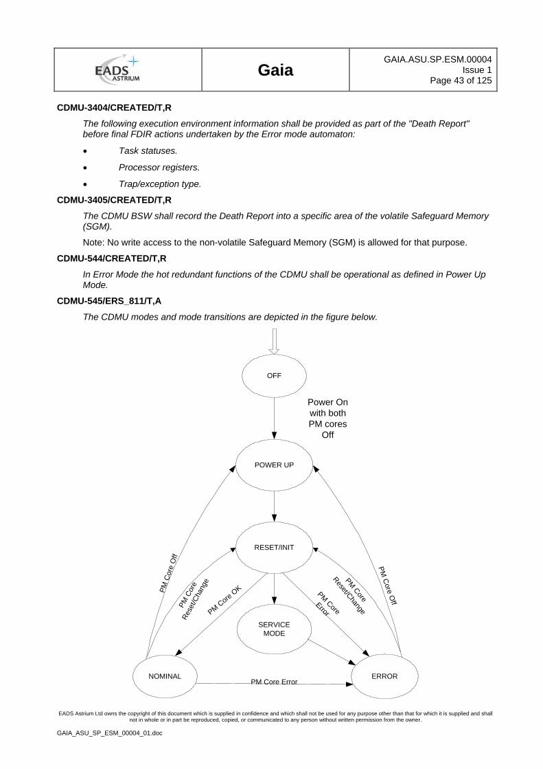
Gaia
GAIA.ASU.SP.ESM.00004Issue 1
Page 43 of 125
EADS Astrium Ltd owns the copyright of this document which is supplied in confidence and which shall not be used for any purpose other than that for which it is supplied and shall not in whole or in part be reproduced, copied, or communicated to any person without written permission from the owner.
GAIA_ASU_SP_ESM_00004_01.doc
CDMU-3404/CREATED/T,R
The following execution environment information shall be provided as part of the "Death Report" before final FDIR actions undertaken by the Error mode automaton:
• Task statuses.
• Processor registers.
• Trap/exception type.
CDMU-3405/CREATED/T,R
The CDMU BSW shall record the Death Report into a specific area of the volatile Safeguard Memory (SGM).
Note: No write access to the non-volatile Safeguard Memory (SGM) is allowed for that purpose.
CDMU-544/CREATED/T,R
In Error Mode the hot redundant functions of the CDMU shall be operational as defined in Power Up Mode.
CDMU-545/ERS_811/T,A
The CDMU modes and mode transitions are depicted in the figure below.
OFF
POWER UP
Power Onwith bothPM cores
Off
RESET/INIT
SERVICEMODE
NOMINAL ERRORPM Core Error
PM C
ore Off
PM C
ore
Off
PM C
ore
Rese
t/Cha
nge PM Core
Reset/Change
PM CoreErrorPM Core O
K
Gaia
GAIA.ASU.SP.ESM.00004Issue 1
Page 44 of 125
EADS Astrium Ltd owns the copyright of this document which is supplied in confidence and which shall not be used for any purpose other than that for which it is supplied and shall not in whole or in part be reproduced, copied, or communicated to any person without written permission from the owner.
GAIA_ASU_SP_ESM_00004_01.doc
3.4 Electrical Design and Interface Requirements
3.4.1 Primary Power Interface and Power Consumption
CDMU-549/ERS_45,ERS_371, ERS_369, ERS_373, ERS_372/T,A,R
The CDMU shall accept to be supplied according to Figure below, with regulated primary power via
• two Foldback Current Limiters (FCL class B)
• two Latching Current Limiters (LCL class A)
• two Latching Current Limiters (LCL class B))
with the electrical characteristics according to [AD 2].
The generation of all secondary voltages shall be performed within the CDMU.
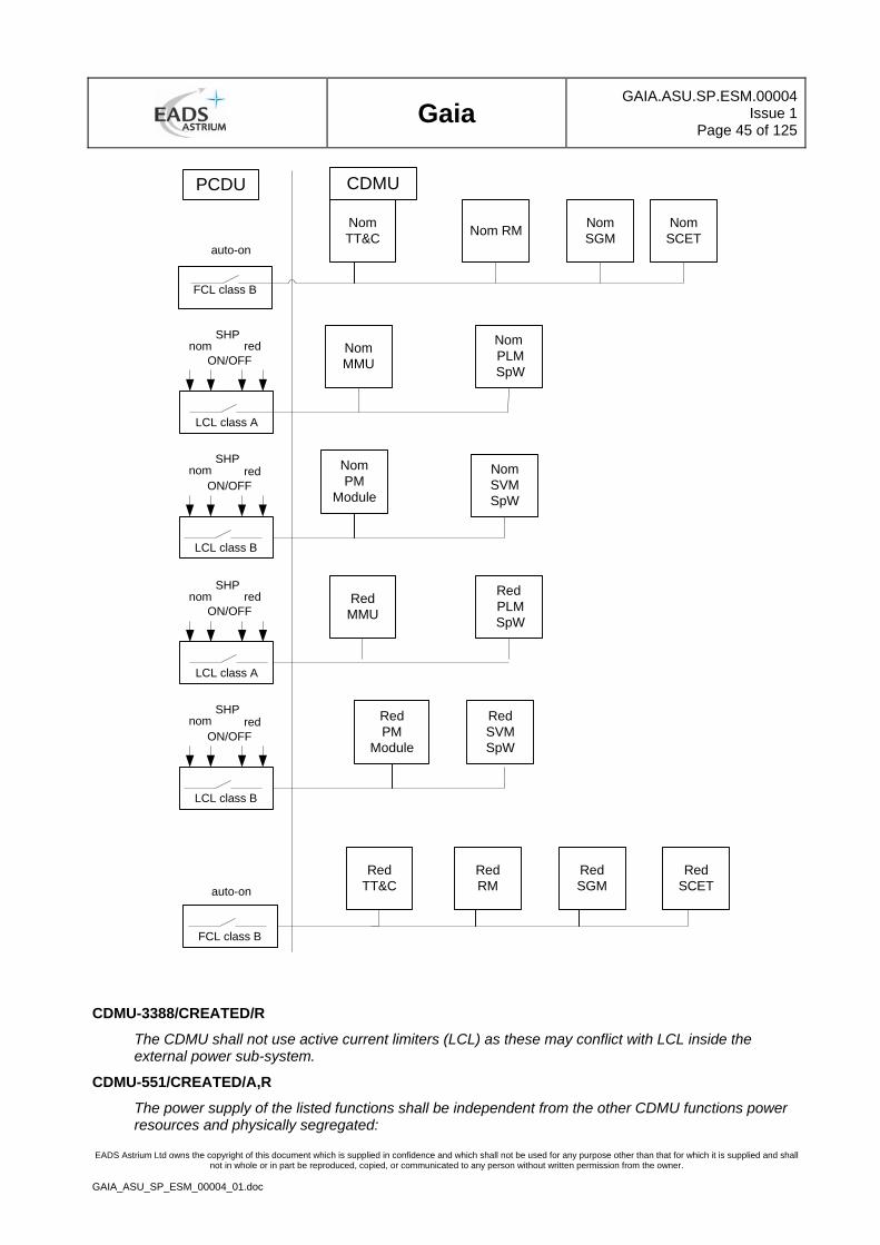
Gaia
GAIA.ASU.SP.ESM.00004Issue 1
Page 45 of 125
EADS Astrium Ltd owns the copyright of this document which is supplied in confidence and which shall not be used for any purpose other than that for which it is supplied and shall not in whole or in part be reproduced, copied, or communicated to any person without written permission from the owner.
GAIA_ASU_SP_ESM_00004_01.doc
NomMMU
Nom PLM SpW
LCL class A
nom redSHP
ON/OFF
RedMMU
Red PLM SpW
LCL class A
nom redSHP
ON/OFF
NomSVMSpW
LCL class B
nom redSHP
ON/OFF
RedPM
Module
LCL class B
nom redSHP
ON/OFF
FCL class B
auto-on
FCL class B
NomTT&C
auto-onNom RM Nom
SGMNomSCET
PCDU CDMU
NomPM
Module
RedSVMSpW
RedTT&C
RedRM
RedSGM
RedSCET
CDMU-3388/CREATED/R
The CDMU shall not use active current limiters (LCL) as these may conflict with LCL inside the external power sub-system.
CDMU-551/CREATED/A,R
The power supply of the listed functions shall be independent from the other CDMU functions power resources and physically segregated:
Gaia
GAIA.ASU.SP.ESM.00004Issue 1
Page 46 of 125
EADS Astrium Ltd owns the copyright of this document which is supplied in confidence and which shall not be used for any purpose other than that for which it is supplied and shall not in whole or in part be reproduced, copied, or communicated to any person without written permission from the owner.
GAIA_ASU_SP_ESM_00004_01.doc
• Telecommand Decoder Function
• Reconfiguration Function (RU)
• Command Pulse Distribution Function (CPDU)
• SCET Function
CDMU-552/ERS_762/T,A,R
No spurious commands shall be generated during power-on, power-off or due to failure of DC/DC converters.
CDMU-2325/ERS_920/T,A
The stability of power dissipation during continuous steady operation and nominal scanning shall be less than 2 % [TBC]over 6 hours when fed from a power bus of 28V +/- 0.25%. See [AD 2].
The following test configuration shall be used:-
• Continuous 10Mps downlink telemetry
• No mode switching
• No Telecommands
• CDMU in "Normal Mode" of operation with basic software(BSW) running.
• such that the stability can be positively verified within this limit for the duration. Knowledge of the absolute value is not required for this test.
3.4.2 Transponder Interface Function (TIF)
3.4.2.1 Telecommand Signal Interface
CDMU-559/CREATED/T,R
The CDMU shall provide 2 Telecommand Signal Interfaces (1 to the main and 1 to the redundant TC-Decoder) with the electrical characteristics and timing according to Section [AD 2], (Interface Data Sheet "DTC").
CDMU-560/CREATED/T,R
Each TC Signal Interface (X-Band Digital TC Channel) shall comprise (tbc):
• TC Data
• TC Clock
• TC Data Valid (DCE) [Enable/Channel Active]
CDMU-561/CREATED/A
The failure propagation in case of a failure in the TC Signal Interface shall be limited to the loss of max. 1 TC Decoder.
3.4.2.2 Receiver Lock Status Interface
CDMU-563/CREATED/T,R
The CDMU shall provide 2 Receiver Lock Status interfaces (1 to the main and 1 to the redundant TC-Decoder) with the electrical characteristics and timing according to [AD 2], (Interface Data Sheet "RLS")..
CDMU-564/CREATED/A
The failure propagation in case of a failure in the Receiver Lock Status interface shall be limited to the loss of max. 1 Receiver Lock Status interface.
Gaia
GAIA.ASU.SP.ESM.00004Issue 1
Page 47 of 125
EADS Astrium Ltd owns the copyright of this document which is supplied in confidence and which shall not be used for any purpose other than that for which it is supplied and shall not in whole or in part be reproduced, copied, or communicated to any person without written permission from the owner.
GAIA_ASU_SP_ESM_00004_01.doc
3.4.2.3 Telemetry Signal Interface
CDMU-566/CREATED/T,R
The CDMU shall provide 2 Telemetry Signal Interfaces (1 to the main and 1 to the redundant TFG) with the electrical characteristics and timing according to [AD 2], (Interface Data Sheet "DTM").
CDMU-567/CREATED/T,R
Each Telemetry Signal Interface (X-Band Digital Telemetry Channel) shall comprise the Telemetry Data (DMD) stream and Telemetry Clock.
CDMU-3378/CREATED/T,A
The Telemetry data rate shall be variable with a maximum rate of 10Mbps.
CDMU-3431//T,A
The Telemetry clock frequency shall be selectable as Nominal (matches data) or 32kHz (sub-carrier to the Transponder)
CDMU-568/CREATED/A
The failure propagation in case of a single failure in the Telemetry Signal interface shall be limited to the loss of max. 1 Telemetry Signal interface.
3.4.3 Command, Monitoring, Data Transfer and Synchronisation Interfaces
3.4.3.1 Mil-Std-1553B Interface
CDMU-744/ERS_450/R
The CDMU shall provide two Redundant MIL-STD-1553 B Data Bus Interfaces with the electrical characteristics according to [AD 2] and [AD 5].
CDMU-745/ERS_451/T,R
The CDMU shall communicate with service modules and Payload module equipment via two redundant MIL-STD-1553 B Data Bus, each capable of 1 Mbps.
CDMU-746/ERS_451/T,R
The CDMU Processor Module shall be the Bus Controller for both redundant MIL-STD-1553 B data buses.
CDMU-747/ERS_450/T,R
Cross-strapping shall be implemented between the Processor Modules and the external data buses (main & red).
CDMU-748/ERS_852/T,A,R
Each Processor Module shall be able to withstand a useful traffic on each MIL-STD-1553B bus of at least 700 kbps (tbc).
CDMU-749/CREATED/T,R
The CDMU shall be able to cyclically transmit a synchro broadcast message onto the MIL-STD-1553B bus. The frequency shall be derived from the SCET.
CDMU-750/CREATED/T,A,R
Based on the definition of the RTC slot frequency, the CDMU shall be able to initiate deterministic exchanges of MIL-STD-1553B bus messages outlined in [AD 5].
CDMU-751/ERS_852, ERS_853/A,R
Adequate hardware means shall be implemented to minimize the load induced by the data bus management on the Application Software in accordance with [AD5].
Gaia
GAIA.ASU.SP.ESM.00004Issue 1
Page 48 of 125
EADS Astrium Ltd owns the copyright of this document which is supplied in confidence and which shall not be used for any purpose other than that for which it is supplied and shall not in whole or in part be reproduced, copied, or communicated to any person without written permission from the owner.
GAIA_ASU_SP_ESM_00004_01.doc
CDMU-752/CREATED/A
The failure propagation of a single failure in the MIL-STD-1553B Data Bus Interface may only result in the loss of this MIL-STD-1553B Data Bus, but shall not propagate to the other MIL-STD-1553B Data Bus Interface, i.e. the cross-strapping of the alternate MIL-STD-1553B Data Bus Interface to the nominal Processor Module and the redundant Processor Module shall not be affected. This applies to both PLM and SVM buses individually.
CDMU-3389/ERS_856/A
If devices are implemented that are common to both the prime and redundant Milbus, then special precautions shall be taken to ensure that no credible failures can result in permanent occupation ( jamming) of both buses.
3.4.3.2 SpaceWire Interface
CDMU-3391/ERS_455/R
The CDMU shall provide (9 nom + 9 red) SpaceWire (SpW) interfaces in hot redundancy and allocated as follows:-
• (4 nom + 4 red ) for science data from PLM
• (2 nom + 2 red) for interface with EIU(with cross strapping, TBC at KO + 4 months)
• (2 nom + 2 red) for SVM (TBC at KO+4).
• (1 nom + 1 red) for Test/EGSE SpaceWire Interface (SIF).
CDMU-3392/CREATED/A,R
The Spacewire Interfaces shall be compliant with [AD 2].
CDMU-3393/ERS_819/T,R
The Spacewire Interface data signalling rate for SVM and EIU shall be programmable upto 10 Mbps.
CDMU-3448//T,A
The Spacewire Interface data signalling rate for science data from the PLM shall be programmable upto 40 Mbps
CDMU-3449//T,A
The CDMU shall withstand a data throughput from the PLM of 2000 packets/second with a packet size varying from 300 bytes to 32 Kbytes.
CDMU-3437/ERS_818/T,A
The Spacewire data signalling rate for Test/EGSE shall be programmable to 10Mbps.
CDMU-3394/CREATED/A
No single failure within the CDMU shall cause the loss of prime and redundant Spacewire link to any user.
CDMU-3395/CREATED/T,R
The interface shall be implemented with the electrical characteristics according to [AD 2]/ section 3.5.5.1
CDMU-3396/CREATED/A
The failure propagation of a single failure in the SpaceWire Interface shall be limited to the loss of 1 SpaceWire Interface.
Gaia
GAIA.ASU.SP.ESM.00004Issue 1
Page 49 of 125
EADS Astrium Ltd owns the copyright of this document which is supplied in confidence and which shall not be used for any purpose other than that for which it is supplied and shall not in whole or in part be reproduced, copied, or communicated to any person without written permission from the owner.
GAIA_ASU_SP_ESM_00004_01.doc
3.4.3.3 ON/OFF Pulse Interface
CDMU-754/ERS_45/R
The CDMU shall provide in total (64 nom + 64 red, ) ON/OFF Pulse Commands operated in hot redundancy and allocated as follows:-
• (64 nom + 64 red) , HPC-type1 (originated from TC Decoder) & HPC-type2 (originated from RM).
This excludes any commands needed for internal switching.
CDMU-755/ERS_45/T,A
The CDMU shall provide each ON/OFF Pulse Command with the electrical characteristics according to [AD 2]/section 3.5.5.8.1 "Standard High Power On/Off Command" (Interface Data Sheet "SHP"; Driver: CDMU).
For CPDU commands the pulse duration shall depend on the value transmitted in the Pulse Duration Field of the relevant Telecommand Source Packet
3.4.3.4 PPS Interface
CDMU-760/ERS_45/R
The CDMU shall provide in total (10 nom + 10 red) PPS (Pulse Per Second) output Interfaces.
CDMU-761/CREATED/T,A
The CDMU shall provide each PPS Interface with the electrical and timing characteristics according to [AD 2] (Interface Data Sheet "PPS").
CDMU-762/CREATED/A
The failure propagation of a single failure in the PPS Interface shall be limited to the loss of max. 1 PPS Interface.
3.4.3.5 2PPS Interface
CDMU-764/ERS_924/R
The CDMU shall provide in total (4 nom + 4 red) 2PPS output Interfaces (tbc).
CDMU-765/ERS_924/T,R
The CDMU shall provide each 2PPS Interface with the electrical and timing characteristics according to [AD 2] (Interface Data Sheet "PPS").
CDMU-766/ERS_924/A
The failure propagation of a single failure in the 2PPS Interface shall be limited to the loss of max. 1 2PPS Interfaces.
3.4.3.6 8PPS Second Interface
CDMU-768/CREATED/R
The CDMU shall provide in total (8 nom + 8 red) 8PPS output Interfaces.
CDMU-769/CREATED/T,R
The CDMU shall provide each 8PPS Interface with the electrical and timing characteristics according to [AD 2] (Interface Data Sheet "PPS").
CDMU-770/CREATED/A
The failure propagation of a single failure in the 8PPS Interface shall be limited to the loss of max. 1 8PPS Interfaces.
Gaia
GAIA.ASU.SP.ESM.00004Issue 1
Page 50 of 125
EADS Astrium Ltd owns the copyright of this document which is supplied in confidence and which shall not be used for any purpose other than that for which it is supplied and shall not in whole or in part be reproduced, copied, or communicated to any person without written permission from the owner.
GAIA_ASU_SP_ESM_00004_01.doc
3.4.3.7 One Hz Synchronisation Pulse Interface
CDMU-772/ERS_45/R
The CDMU shall provide in total (1 nom + 1 red) 1Hz Sync Pulse Receiver Interfaces from the Clock Distribution Unit ( CDU).
CDMU-773/ERS_923/T,R
The CDMU shall provide each 1Hz Sync Pulse Receiver Interface with the electrical and timing characteristics according to [AD 2] (Interface Data Sheet "1SY").
CDMU-774/ERS_923/A
The failure propagation of a single failure in the 1Hz Sync Pulse Receiver Interface shall be limited to the loss of max. one 1Hz Sync Pulse Interface.
3.4.3.8 TFG Time Strobe Interface
CDMU-776/ERS_809/R
The CDMU shall provide in total (2 nom + 2 red) TFG Time strobe (TFGTS) Interfaces.
CDMU-777/CREATED/T,R
The CDMU shall provide each TFG Time strobe Interface with the electrical and timing characteristics according to [AD 2] (Interface Data Sheet "TFG Time Strobe").
CDMU-778/CREATED/A
The failure propagation of a single failure in the TFGTS transmitter Interface shall be limited to the loss of max. 1 TFG Time strobe Interface.
3.4.3.9 Separation Strap Acquisition Interface
CDMU-786/ERS_45/R
The CDMU shall provide (3 nom and 3 red) Separation Strap Acquisition Interfaces (SSA).
CDMU-787/CREATED/T,R
These Separation Strap Acquisition Interfaces shall be independent from each other.
CDMU-788/CREATED/T,R
The status of each Separation Strap Acquisition shall be made available for Software through H/W acquisition paths with no common failures modes.
CDMU-3451/CREATED/T,A
The FMEC/HSIA shall demonstrate that a single failure can only cause one of the three separation status.
CDMU-789/CREATED/T,R
The CDMU shall provide each Separation Strap Acquisition Interface (SSA) with the electrical characteristics according to the type Relay acquisition interface (Interface Data Sheet "RSA"; Receiver: CDMU) defined in [AD 2]
CDMU-790/CREATED/A
The failure propagation of a single failure in the Separation Strap acquisition interface shall be limited to the loss of max. 1 Separation Strap Interface.
CDMU-791/CREATED/T,R
Each Separation Strap Acquisition function shall be cross-strapped to CDMU Processor Module A and B.
Gaia
GAIA.ASU.SP.ESM.00004Issue 1
Page 51 of 125
EADS Astrium Ltd owns the copyright of this document which is supplied in confidence and which shall not be used for any purpose other than that for which it is supplied and shall not in whole or in part be reproduced, copied, or communicated to any person without written permission from the owner.
GAIA_ASU_SP_ESM_00004_01.doc
3.4.3.10 Alarm Input Channel Interface
CDMU-793/ERS_870/R
The CDMU shall provide in total of 8 Alarm Input Channel Interfaces.
CDMU-794/CREATED/T,R
The CDMU shall provide each Alarm Input Channel Interface with the electrical characteristics according to section 4.3.1.6 (Interface Data Sheet "SAC, SAD").
CDMU-3442/ERS_871/T,A
Each external alarm shall be configurable either as "enables" or "disabled" by a telecommand on ground or in flight.
CDMU-3443/ERS_872/T,A
The filtering time of a system alarm shall be programmable on ground or in flight.
CDMU-795/CREATED/A
The failure propagation of a single failure in the Alarm Input Channel Interface shall be limited to the loss of max. 4 Alarm Input Channel Interfaces.
3.4.3.11 CDMU Test Interfaces
3.4.3.11.1 General
CDMU-816/ERS_45,GDI-973/R
The CDMU shall provide at least the following test interfaces to the Electrical Ground Support Equipment (EGSE) needed for the system level check-out:
• Telecommand Test Interface
• Telemetry Test Interface
• Spacewire link interface for fast software loading/dumping and monitoring (SIF)
• Time Synchronisation Test Interface
• UART LVDS for fast software loading/dumping and monitoring (SIF)
CDMU-817/CREATED/R
The CDMU shall provide adequate test interfaces for unit-level integration and test.
CDMU-818/CREATED/T,R
The Processor Module shall provide by dedicated interface access to processor control (halt/ restart, set breakpoints, step-by-step command execution) to its registers (read/ write) and to the memory area (load/ unload/ patch/ dump).
CDMU-819/CREATED/R
Protection shall be implemented in accordance with [AD 2].
3.4.3.11.2 Telecommand Test Interface
CDMU-821/GDI_973, ERS_823/R
Each Command Decoder shall provide one EGSE auxiliary TC interface (X-Band Digital TC Bypass Channel) dedicated to the Packet Telecommand Decoder. This test interface shall comprise EGSE TC Bypass Data Signal, EGSE TC Bypass Clock and EGSE TC Bypass Data Valid (Active) Signal.
CDMU-822/ERS_823/T,R
The EGSE auxiliary digital TC interface shall support a data rate compatible with the normal up-link transmission data rate.
Gaia
GAIA.ASU.SP.ESM.00004Issue 1
Page 52 of 125
EADS Astrium Ltd owns the copyright of this document which is supplied in confidence and which shall not be used for any purpose other than that for which it is supplied and shall not in whole or in part be reproduced, copied, or communicated to any person without written permission from the owner.
GAIA_ASU_SP_ESM_00004_01.doc
CDMU-823/CREATED/T,R
Telecommands on the EGSE TC interface shall be received on CLTU level including Acquisition Sequence and Idle Sequences.
CDMU-824/ERS_823/A
The failure propagation in case of a single failure in the EGSE TC interface shall be limited to the loss of max. 1 Telecommand Decoder interface.
CDMU-825/ERS_823/T,R
The EGSE TC interface shall be implemented with the electrical characteristics according to [AD 2] (Interface Data Sheet "ETC").
CDMU-826/ERS_823/R
The CPDU Status Word and the Frame Analysis Reports (FAR) shall be made available to the EGSE for system level tests.
3.4.3.11.3 Telemetry Test Interface
CDMU-828/GDI_973/R
Each TM Module (X-Band TFG) shall provide an EGSE auxiliary TM interface (X-Band Digital TM Bypass Channel) comprising EGSE TM Bypass Data Signal and EGSE TM Bypass Clock.
CDMU-829/CREATED/A
In case of a single failure, the failure propagation in the EGSE TM interface shall be limited to the loss of max. 1 TM interface.
CDMU-830/CREATED/T,R
The interface shall be implemented with the electrical characteristics according to [AD 2] (Interface Data Sheet "ETM")
3.4.3.11.4 Synchronisation Test Interface
CDMU-836/GDI_973/T,R
The CDMU shall provide redundant 1 Hz Synchronisation Signals(from PLM CDU) via dedicated buffers to the EGSE.
CDMU-3379/CREATED/T,A
The timing delay uncertainty under EGSE test conditions shall be < 20ns and calibrated.
CDMU-837/CREATED/T,R
The interface shall be implemented with the electrical characteristics according to [AD 2] (Interface Data Sheet "E1S").
CDMU-838/CREATED/A
In case of a single failure, the failure propagation in the Synchronisation test interface shall be limited to the loss of max. 1 interface.
3.4.3.11.5 SW Load /Dump UART Interface
CDMU-840/GDI_973/R
Each processor Module shall provide a UART RS-422 Serial Link Interface for software loading/dumping and monitoring.
CDMU-841/CREATED/T,R
The interface shall comprise the following signals
• EUL-TD (EUT) transmit line as seen from the CDMU
• EUL-RD (EUR) receive line as seen from the CDMU
Gaia
GAIA.ASU.SP.ESM.00004Issue 1
Page 53 of 125
EADS Astrium Ltd owns the copyright of this document which is supplied in confidence and which shall not be used for any purpose other than that for which it is supplied and shall not in whole or in part be reproduced, copied, or communicated to any person without written permission from the owner.
GAIA_ASU_SP_ESM_00004_01.doc
and shall be implemented with the electrical characteristics according to [AD 2] (Interface Data Sheet "EUL").
CDMU-842/CREATED/A
In case of a single failure, the failure propagation in the SW Load/Dump UART interface shall be limited to the loss of max. 1 interface.
3.4.4 Spacewire Test Interface
CDMU-844/GDI_973/R
The CDMU shall provide (2 nom + 2 red) Spacewire Interfaces (EGSE, RTS) .
CDMU-2326/CREATED/R
The Spacewire Interfaces shall be compliant with [AD 2].
CDMU-2328/CREATED/T,R
The data rate shall be programmable upto 40 Mbps.
CDMU-3380/CREATED/A
No single failure within the CDMU shall cause the loss of prime and redundant Spacewire link to any user.
CDMU-3386/CREATED/R
The interface shall be implemented with the electrical characteristics according to [AD 2]/ section 3.5.5.1
CDMU-846/CREATED/A
The failure propagation of a single failure in the SpaceWire Interface shall be limited to the loss of 1 SpaceWire Interface.
3.5 CDMU Software Requirements
CDMU-858/CREATED/R
The CDMU Software shall comprise the following software packages:
CDMU-859/CREATED/R
Basic Software consisting of:
• Start-Up Software, initiated by power-on or reset and performing initialisation, self-tests, loading and start of the Application SW
• Application Program Interface (API) Software, forming the interface between the CDMU HW and the Application SW such that all APSW access to CDMU HW is via the API SW only.
3.5.1 Start-Up Software (SUSW)
3.5.1.1 Start-Up Software Mode & Transition Diagram
CDMU-861/CREATED/R
The CDMU contractor shall design, develop and test the Start-Up Software (SUSW).
CDMU-2175/CREATED/T,A,I
The CDMU Start-Up SW (SUSW) shall operate in accordance with the software mode and transition diagram as shown below:
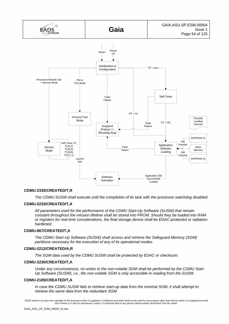
Gaia
GAIA.ASU.SP.ESM.00004Issue 1
Page 54 of 125
EADS Astrium Ltd owns the copyright of this document which is supplied in confidence and which shall not be used for any purpose other than that for which it is supplied and shall not in whole or in part be reproduced, copied, or communicated to any person without written permission from the owner.
GAIA_ASU_SP_ESM_00004_01.doc
LaunchSW
Initialisation &Configuration
Self-Tests
ApplicationSoftwareLoading
ServiceMode
Suspend(Failure =>
Reconfig Seq)
SoftwareActivation
MassMemory
EEPROM #1
EEPROM #2
ST = yes
SWPackets
SWPackets
ST = OK
FatalFailure
ST = no
FatalFailure
FatalFailure
Application SWSuccessfully
Loaded
Processor Module role= Service Mode
Self-Tests TCTC(6,2)TC(6,5)TC(6,9)TC(17,1)
PowerOnReset
PossibleLoadingSources
Ground TestMode
PM inTest Mode
CDMU-2330/CREATED/T,R
The CDMU SUSW shall execute until the completion of its task with the processor watchdog disabled.
CDMU-2233/CREATED/T,A
All parameters used for the performance of the CDMU Start-Up Software (SUSW) that remain constant throughout the mission lifetime shall be stored into PROM. Should they be loaded into RAM or registers for real-time considerations, the final storage device shall be EDAC-protected or radiation-hardened.
CDMU-867/CREATED/T,A
The CDMU Start-Up Software (SUSW) shall access and retrieve the Safeguard Memory (SGM) partitions necessary for the execution of any of its operational modes.
CDMU-2212/CREATED/A,R
The SGM data used by the CDMU SUSW shall be protected by EDAC or checksum.
CDMU-2230/CREATED/T,A
Under any circumstances, no writes to the non-volatile SGM shall be performed by the CDMU Start-Up Software (SUSW), i.e., the non-volatile SGM is only accessible in reading from the SUSW.
CDMU-2185/CREATED/T,A
In case the CDMU SUSW fails to retrieve start-up data from the nominal SGM, it shall attempt to retrieve the same data from the redundant SGM.
Gaia
GAIA.ASU.SP.ESM.00004Issue 1
Page 55 of 125
EADS Astrium Ltd owns the copyright of this document which is supplied in confidence and which shall not be used for any purpose other than that for which it is supplied and shall not in whole or in part be reproduced, copied, or communicated to any person without written permission from the owner.
GAIA_ASU_SP_ESM_00004_01.doc
CDMU-2186/CREATED/T,A
In case the CDMU SUSW fails to retrieve start-up data from the redundant SGM, it shall perform the transition into the Suspend State.
CDMU-866/CREATED/T,A
The CDMU SUSW shall under all circumstances ensure that the boot process terminates in one of the three following modes and that the boot report is generated:
• Service Mode, if the role of the CDMU Processor Module is to operate in Service Mode executing ground or Application Software requests routed from the active processor where the Application Software runs.
• Software Activation, where control is released to the Application Software.
• Suspend State, where the SUSW ultimately generates an Alarm that is forwarded to the Reconfiguration Unit for treatment.
3.5.1.2 Suspend State
CDMU-2179/CREATED/T,A
During its execution, the CDMU Start-Up Software (SUSW) shall record all the errors to enable the Application Software to retrieve needed information.
CDMU-2176/CREATED/T,A
A fatal failure shall be identified as an error having occurred at least twice which prevents the CDMU SUSW from performing the transition into the next operational mode and safely executing the complete sequence until the Application Software is successfully activated and control released to it.
CDMU-2180/CREATED/T,A
In case of a fatal failure, the CDMU SUSW shall build up a "Death Report" containing the data necessary to diagnose the root cause of the error and fatal failure.
CDMU-2181/CREATED/T,A
The following execution environment information shall be provided as part of the "Death Report" before final FDIR actions undertaken by the Suspend State automaton:
• Task statuses.
• Processor registers.
• Trap/exception type.
CDMU-2182/CREATED/T,A
The CDMU SUSW shall record the Death Report into a specific area of the volatile Safeguard Memory (SGM).
Note: No write access to the non-volatile Safeguard Memory (SGM) is allowed for that purpose.
CDMU-2183/CREATED/T,A
In the Suspend State, the CDMU SUSW shall generate an Alarm in order to trigger the next CDMU reconfiguration sequence.
3.5.1.3 Initialisation & Configuration
CDMU-862/CREATED/T,A
The CDMU Start-Up SW (SUSW) shall be started upon the following conditions:
• CDMU power-on (cold reset)
• CDMU reset (warm reset)
Gaia
GAIA.ASU.SP.ESM.00004Issue 1
Page 56 of 125
EADS Astrium Ltd owns the copyright of this document which is supplied in confidence and which shall not be used for any purpose other than that for which it is supplied and shall not in whole or in part be reproduced, copied, or communicated to any person without written permission from the owner.
GAIA_ASU_SP_ESM_00004_01.doc
CDMU-863/CREATED/T,A
A cold reset is defined as occurring when power is applied to the Processor Module, i.e going from the OFF state to the ON state by powering the Processor Module OFF and ON again.
CDMU-864/CREATED/T,A
A warm reset is defined as occurring when a Processor Module is in the ON state and a reset is generated. The warm reset is generated by issuing a HPC from the CPDU either from a Direct TC from ground (HPC-type 1), from a reconfiguration sequence (HPC-type 2) or by the Application SW.
CDMU-865/CREATED/T,A
The CDMU SUSW shall perform the following initialisation and configuration functions as a minimum:
• Bootstrap
• PM Configuration
• SUSW Data retrieval.
3.5.1.3.1 Bootstrap
CDMU-2188/CREATED/T,A
The CDMU SUSW bootstrap shall execute in the CDMU Processor Module PROM.
CDMU-868/CREATED/T,A
The CDMU SUSW bootstrap shall first provide tests and initialisation of the CDMU Processor Module hardware functions excluding any EIU data communication interface. As a minimum, the following tests and initialisation shall be performed with a logical sequence to be proposed by the CDMU supplier:
• Processor watchdog disabling.
• Test of the ERC32 internal features.
• Interrupt control initialisation.
• Memory access (wait states) and memory management initialisation.
• Memory protection initialisation (Write, EDAC).
• Access tests to all HW registers.
• CDMU power-on detection and recording.
• Time initialisation.
• Test of the floating point unit.
CDMU-2187/CREATED/T,A
The CDMU SUSW bootstrap shall test the Processor Module RAM area, which size allows loading the SUSW from PROM into RAM.
CDMU-2191/CREATED/T,A
If the test of RAM area is successful, the bootstrap shall copy the SUSW into RAM area.
CDMU-2194/CREATED/T,A
Else, if the test of RAM area fails, the bootstrap shall enter the Suspend State.
CDMU-2189/CREATED/T,A
At the end of the bootstrap sequence, the CDMU SUSW shall start executing in RAM if a healthy RAM area could be found.
Gaia
GAIA.ASU.SP.ESM.00004Issue 1
Page 57 of 125
EADS Astrium Ltd owns the copyright of this document which is supplied in confidence and which shall not be used for any purpose other than that for which it is supplied and shall not in whole or in part be reproduced, copied, or communicated to any person without written permission from the owner.
GAIA_ASU_SP_ESM_00004_01.doc
3.5.1.3.2 PM Configuration
CDMU PM Role Determination
CDMU-2195/CREATED/T,A
The SUSW configuration function shall determine which role the CDMU Processor Module being initialised must play:
• Active PM,
• or, PM in Service Mode,
• or, PM in Ground Test Mode.
CDMU-2201/CREATED/T,A
No single failure of the CDMU SUSW PM role determination process nor single failure of the information it uses for the execution of that process shall make the following feared events occur:
• Erroneous/spurious detection of test connector presence.
• Erroneous/spurious detection of PM role = Service Mode with no active processor.
• Missing detection of PM=Service mode when the other processor is active.
CDMU-871/CREATED/T,A
In case the EGSE link test connector is connected, the CDMU Start-Up SW shall wait for set-up test commands received via the Fast SW Load/ Dump Interface or the SpaceWire Test Interface (SIF). Details to be agreed via ICD.
CDMU-2207/CREATED/T,A
Upon reception of initial ground set-up test command, the CDMU SUSW shall enter the Ground Test Mode.
CDMU-873/CREATED/T,A
If no initial ground set-up test command is received by the SUSW within a time period defined and agreed via ICD, the CDMU SUSW shall automatically enter the idle state..
CDMU-2202/CREATED/T,A
The PM in Service Mode case shall be eligible if there already exists an active PM, i.e., a CDMU PM that already executes the Application Software.
CDMU-2208/CREATED/T,A
Upon reception of initial command through the inter-processor link, the CDMU SUSW shall enter the Service Mode.
CDMU-2204/CREATED/T,A
If no initial service mode command is received by the SUSW through the inter-processor link within a time period defined and agreed via ICD, the PM Service mode shall automatically enter the Suspend mode.
Reconfiguration Unit Configuration
CDMU-2206/CREATED/T,A
The CDMU SUSW shall establish the link with the Reconfiguration Unit (RU).
CDMU-2209/CREATED/T,A
The CDMU SUSW shall configure the Reconfiguration Unit (RU) for allowing the access to the Safeguard Memory (SGM).
Gaia
GAIA.ASU.SP.ESM.00004Issue 1
Page 58 of 125
EADS Astrium Ltd owns the copyright of this document which is supplied in confidence and which shall not be used for any purpose other than that for which it is supplied and shall not in whole or in part be reproduced, copied, or communicated to any person without written permission from the owner.
GAIA_ASU_SP_ESM_00004_01.doc
CDMU-2210/CREATED/T,A
The CDMU SUSW shall retrieve the Application Software loading information from the Safeguard Memory (SGM).
CDMU-2211/CREATED/T,A
As a minimum, the Application Software loading information shall contain the following data items:
• Self-Test Bypass (STB) flag: specifying whether the self-test must be bypassed ("yes") or not ("no").
• Loading sources with associated enabled/disabled status: CDMU PM EEPROM area 1, CDMU PM EEPROM area 2, CDMU Mass Memory Unit.
• Patch information for each area: "patch", "no patch".
• Start address and size of CDMU PM RAM to check.
• EEPROM area 1 address of Application Software's 1st packet.
• EEPROM area 1 address of Application Software's 1st patch packet.
• EEPROM area 2 address of Application Software's 1st packet.
• EEPROM area 2 address of Application Software's 1st patch packet.
• Packet store name of CDMU Mass Memory Unit containing Application Software.
• Packet store name of CDMU Mass Memory Unit containing Application Software patch(es).
CDMU-2231/CREATED/T,A
Only one of the two possible CDMU PM EEPROM areas shall be enabled at a time, either CDMU EEPROM area 1 or CDMU EEPROM area 2.
CDMU-2213/CREATED/T,A
Default information of the loading information shall be stored into CDMU PM PROM with the following default values:
• Self-Test Bypass (STB) flag: "yes".
• Loading source: CDMU PM EEPROM area 1.
• Patch information: "no patch".
• Start address and size of CDMU PM RAM to check: "00..000016"
• EEPROM area 1 address of Application Software's 1st packet: constant address for EEPROM area 1.
CDMU-2214/CREATED/T,A
In case the CDMU SUSW fails to retrieve the Application Software loading information from the nominal SGM after at least two attempts through different access paths, it shall attempt retrieving the loading information from the redundant SGM.
CDMU-2215/CREATED/T,A
If CDMU SUSW fails to retrieve the Application Software loading information from both nominal and redundant SGM, it shall make a last attempt to load the Application Software using the default values of the loading information.
CDMU-2216/CREATED/T,A
If the last attempt to load the Application Software using the default values of the loading information fails, the CDMU SUSW shall enter the Suspend State.
Gaia
GAIA.ASU.SP.ESM.00004Issue 1
Page 59 of 125
EADS Astrium Ltd owns the copyright of this document which is supplied in confidence and which shall not be used for any purpose other than that for which it is supplied and shall not in whole or in part be reproduced, copied, or communicated to any person without written permission from the owner.
GAIA_ASU_SP_ESM_00004_01.doc
3.5.1.4 Self-Tests
CDMU-2218/CREATED/T,A
If the Self-Test Bypass (STB) flag is set to "yes", the CDMU SUSW shall bypass the self-tests and enter the Application Software Loading mode.
CDMU-2219/CREATED/T,A
Otherwise, if the Self-Test Bypass (STB) flag is set to "no", the CDMU SUSW shall execute the self-tests necessary for guaranteeing that the Application Software can be safely loaded and executed into a healthy and error-protected RAM area.
CDMU-2223/CREATED/T,A
All the self-tests performed by the CDMU SUSW shall be marked as "successful" pending their execution after which the actual self-test result is individually updated.
CDMU-869/CREATED/T,A
A CDMU SUSW self-test report (e.g., test ID, failure status) shall be stored at a predefined address in the volatile Safeguard Memory (SGM).
CDMU-2222/CREATED/T,A
If all the self-tests are successful, i.e., no fatal failure occurred during the execution of each self-test, the CDMU SUSW shall enter the Application Software Loading mode.
CDMU-2220/CREATED/T,A
Otherwise, if a fatal failure occurs during the execution of the self-tests, the CDMU SUSW shall enter the Suspend State.
3.5.1.5 Application Software Loading
CDMU-2228/CREATED/T,A
As specified by the Application Software loading information, the CDMU SUSW shall provide loading of the Application Software image and patches from any of the possible sources:
• CDMU PM EEPROM area 1.
• CDMU PM EEPROM area 2.
• CDMU Mass Memory Unit.
CDMU-2232/CREATED/T,A
The Application Software image and the software patches shall consist of a sequence of telemetry software packets with each packet protected by a checksum.
CDMU-2229/CREATED/T,A
The CDMU SUSW shall load the Application Software and the software patch packets from the specified EEPROM area 1, i.e., CDMU PM EEPROM area 1 or CDMU PM EEPROM area 2.
CDMU-876/CREATED/T,A
The CDMU SUSW shall compute the checksum of each sequential telemetry software packet and shall compare it with the checksum of the dedicated software packet field.
CDMU-2237/CREATED/T,A
In case all the Application Software and patch software packets could be loaded successfully with all checksum computations giving successful results, the CDMU SUSW shall enter the Software Activation mode.
CDMU-2235/CREATED/T,A
In case of a 1st checksum error, the CDMU SUSW shall read and check once again the telemetry software packet.
Gaia
GAIA.ASU.SP.ESM.00004Issue 1
Page 60 of 125
EADS Astrium Ltd owns the copyright of this document which is supplied in confidence and which shall not be used for any purpose other than that for which it is supplied and shall not in whole or in part be reproduced, copied, or communicated to any person without written permission from the owner.
GAIA_ASU_SP_ESM_00004_01.doc
CDMU-2234/CREATED/T,A
In case (i) of the occurrence of a 2nd checksum error and (ii) the CDMU Mass Memory loading source is disabled, this shall be considered as a fatal failure and consequently the CDMU SUSW shall enter the Suspend State.
CDMU-2236/CREATED/T,A
In case (i) of a 2nd checksum error and (ii) the CDMU Mass Memory loading source is enabled, the CDMU SUSW shall load the Application Software image and patches from the CDMU Mass Memory Unit.
CDMU-2238/CREATED/T,A
If the loading of the Application Software image and patches from the Mass Memory Unit is successful, then the CDMU SUSW shall enter the Software Activation mode.
CDMU-2239/CREATED/T,A
If loading of the Application Software image and patches from the Mass Memory Unit is unsuccessful, this shall be considered as a fatal failure and consequently the CDMU SUSW shall enter the Suspend State.
CDMU-3410/CREATED/T,A
In case of checksum error during software loading the boot report shall include a report calculated checksum, the expected checksum and the load address.
3.5.1.6 Software Activation
CDMU-2240/CREATED/T,A
The CDMU Start-Up Software (SUSW) shall initialise and configure the CDMU resources necessary for the Application Software launch.
CDMU-2241/CREATED/T,A
The CDMU SUSW shall start the Application Software in CDMU PM RAM.
CDMU-2242/CREATED/T,A
Should there exist timing constraints (e.g., next watchdog refreshment deadline) from the time of Application Software activation, they shall be defined and agreed in the ICD.
3.5.1.7 Service Mode
CDMU-2243/CREATED/T,A
The CDMU Start-Up Software (SUSW) shall provide a Service Mode automatically activated upon initial command received from the CDMU active processor through the inter-processor link.
CDMU-2244/CREATED/T,A
The CDMU SUSW Service Mode shall provide the following services:
• PM Memory load using absolute addresses: TC(6,2).
• PM Memory dump using absolute addresses: TC(6,5).
• PM Memory check using absolute addresses: TC(6,9).
• Connection test: TC(17,1).
• Execute single self-test using self-test ID and parameters required for the test boundary limits: type and sub-type of the TC to be defined and agreed in ICD.
• Execute all self-tests: type and sub-type of the TC to be defined and agreed in ICD.
• Launch software using absolute address: type and sub-type of the TC to be defined and agreed in ICD.
Gaia
GAIA.ASU.SP.ESM.00004Issue 1
Page 61 of 125
EADS Astrium Ltd owns the copyright of this document which is supplied in confidence and which shall not be used for any purpose other than that for which it is supplied and shall not in whole or in part be reproduced, copied, or communicated to any person without written permission from the owner.
GAIA_ASU_SP_ESM_00004_01.doc
CDMU-2246/CREATED/T,A
The following CDMU SUSW self-tests shall be made accessible in Service Mode:
• CPU built-in-test.
• timers.
• memory management.
• EDAC.
• RAM.
• PROM.
• EEPROM.
CDMU-2247/CREATED/T,A
In case the CDMU processor in Service Mode detects a inter-processor link disconnect, the CDMU SUSW shall wait and be ready for link re-establishment at CDMU active processor initiative.
CDMU-2248/CREATED/T,A
No single failure shall propagate from a processor and SUSW in Service Mode to the CDMU active processor.
3.5.1.8 Ground Test Mode
CDMU-874/CREATED/T,A
The Start-Up SW shall support the following functions when an EGSE link is present:
• Processor Module memory load (partial or complete)
• Processor Module memory dump (partial or complete)
• Processor Module memory CRC calculation (partial or complete)
CDMU-875/CREATED/T,A
All on-ground test commands shall be provided for RAM and EEPROM memories and a function shall be provided to lock/ unlock the EEPROM memory programming.
3.5.1.9 Start-Up Software Performances
CDMU-2332/CREATED/T,A
When the Self-Test enabled, the CDMU Start-Up Software shall release control to the Application Software less than 20s if self-test is performed or less than 5s if self-test if bypassed after the power on, including one retry for the worst-case activity in terms of execution time (single failure mode).
CDMU-2334/CREATED/T,A
The fault detection/isolation coverage of the CDMU Start-Up Software shall be greater than 95%.
CDMU-2335/CREATED/T,A
The impact of undetected CDMU failures by the Start-Up Software shall documented in the Hardware/Software Interface Analysis (HSIA).
3.5.2 Application Programs Interface Package (API Package)
CDMU-879/CREATED/T,A
The CDMU contractor shall design, develop and test the software for the Application Program Interface (APISW).
Gaia
GAIA.ASU.SP.ESM.00004Issue 1
Page 62 of 125
EADS Astrium Ltd owns the copyright of this document which is supplied in confidence and which shall not be used for any purpose other than that for which it is supplied and shall not in whole or in part be reproduced, copied, or communicated to any person without written permission from the owner.
GAIA_ASU_SP_ESM_00004_01.doc
CDMU-880/CREATED/T,A
Access to all CDMU internal hardware and external data communication channels and IOs shall be provided via APIs.
CDMU-3445/CREATED/T,A
All of the APIs shall minimise the number of I/O accesses that are performed
during their execution, to ensure efficient use is made of all resources.
CDMU-881/CREATED/T,A
The CDMU hardware supplier shall define and agree with the customer the detailed functions of the APISW and its interfaces to the Application SW and shall document this in a dedicated API SW Interface Control Document (API-ICD). The minimum content of the API /ICD shall as follows for each service:-
• Description
• Functional parameters and types
• Expected usage
• Average and worst case execution time, characterised as overhead + time per data unit dependant functions
• Shared resources
• Durations of critical sections and blocking periods for shared resources.
CDMU-882/CREATED/T,A
The CDMU API SW shall comprise a set of services for each CDMU hardware resource, data communication channel and local input/output.
CDMU-3446/CREATED/T,A
All of the APIs shall be coded efficiently, without the use of 'busy-wait' loops or
unnecessary data copying, to maximise the available processing resources.
CDMU-3434/CREATED/T,A
The CDMU API software shall require a maximum of 50 KBytes(TBC) of RAM for data storage during execution., with a 50% margin at PDR and 25% margin at CDR.
CDMU-3435/CREATED/T,A
The CDMU API software shall be stored in EEPROM along with the application software.
CDMU-3436//
The CDMU API shall occupy less than 50 KBytes(TBC) of EEPROM space, with 50% margin at PDR and 25% margin at CDR.
CDMU-2333/CREATED/T,A
The acquisition or transfer of data from/to the data communication channels and local input/output to/from the memory for access by the Application software shall be performed by the APISW.
CDMU-883/CREATED/T,A
The CDMU API SW shall comprise dedicated services to control and monitor all CDMU internal hardware.
CDMU-884/CREATED/T,A
These API SW services shall provide access to the CDMU hardware functional blocks as follows (but needs not to be limited to these):
Gaia
GAIA.ASU.SP.ESM.00004Issue 1
Page 63 of 125
EADS Astrium Ltd owns the copyright of this document which is supplied in confidence and which shall not be used for any purpose other than that for which it is supplied and shall not in whole or in part be reproduced, copied, or communicated to any person without written permission from the owner.
GAIA_ASU_SP_ESM_00004_01.doc
• Telecommand decoder function.
• Telemetry encoding function.
• On-board timing functions.
• Reconfiguration functions.
• Context saving functions (SGM).
• Mass memory functions.
• MIL-STD-1553B interface.
• SpaceWire interface.
The API SW shall allow the Application Software to benefit from the full functionality of these functions as defined in the hardware sections of this specification.
CDMU-885/CREATED/T,A
The API SW shall maintain a pool of CDMU internal housekeeping parameters for access by the APSW. The API SW shall provide calls for reading of all or configurable groups of these parameters.
CDMU-886/CREATED/T,A
The API SW functions shall report the success or failure by return of appropriate parameters.
CDMU-3411/CREATED/T,A
In case of failures , data to determine in detail the cause of failure shall be indicated.
CDMU-887/CREATED/T,A
The services of the API SW shall be protected or re-entrant.
CDMU-889/CREATED/T,A
No use of the Real-Time Operating System (e.g., semaphores, task, active wait) shall be made from the API SW services.
3.5.3 Acceptance Test Software
CDMU-892/CREATED/T,A
In order to allow testing of the APISW with the API interface as used by the APSW contractor and as specified in [AD 7], the CDMU contractor shall design, develop and deliver a set of API test software modules which act as a replacement of the Application Software.
CDMU-893/CREATED/R
The API test software modules shall be delivered as executable and source code, both on electronic medias, such that it can be re-compiled and / or included into system level test software generated by the customer.
CDMU-894/CREATED/T,A
The API software test modules shall allow to test each specified function of the API SW.
CDMU-3412/CREATED/T,A
The test scenario shall be executed that exercises all the CDMU interfaces and functions in parallel.
CDMU-895/CREATED/T,A
The API software test modules shall allow to test the specified end to end functionality including all involved CDMU HW supported by the Basic Software Ground Monitor (Debugger).
CDMU-896/CREATED/T,A
The API software test modules will be used for acceptance testing of the CDMU
Gaia
GAIA.ASU.SP.ESM.00004Issue 1
Page 64 of 125
EADS Astrium Ltd owns the copyright of this document which is supplied in confidence and which shall not be used for any purpose other than that for which it is supplied and shall not in whole or in part be reproduced, copied, or communicated to any person without written permission from the owner.
GAIA_ASU_SP_ESM_00004_01.doc
At the beginning of the CDMU acceptance test, the SUSW shall branch to the acceptance test software entry point.
The acceptance test shall cover loading of SW into RAM and verification of:
• All hardware functions
• All the CDMU hardware/ software interfaces
• The reconfiguration mechanisms
• The specified performances of the CDMU
CDMU-897/CREATED/R
The major features of the acceptance test software shall be as follows:
• A set of software modules whose functions can be selected and activated by the Basic Software Ground Monitor (Debugger) to be provided by the contractor.
• Capability to be loaded into RAM through a ground test equipment serial link.
• Capability to autonomously run without time limitation.
• Capability to re-arm the watchdog.
• Capability to operate the Mil-Std 1553B bus and to control the transmission of a pre-defined frame upon the reception of a telecommand from ground test equipment.
• Capability to transmit telemetry frames.
• Capability to manage the on-board time synchronisation process.
• Capability to operate the SpaceWire link network.
3.5.4 Development Requirements
3.5.4.1 Development Standards
CDMU-900/CREATED/A,R
The tailored version of the ESA Packet Utilisation Standard (PUS) [AD 6] shall be applicable.
CDMU-901/CREATED/R
The subcontractor shall define a software development life cycle in accordance with [AD 3].
CDMU-902/CREATED/T,R
All Basic Software shall be tested (i.e. Module-, Branch-, Function tests) in the CDMU BB and in the FM CDMU prior to delivery.
CDMU-903/CREATED/T,R
All Software Requirements and PUS defined functions shall be tested prior to each delivery.
CDMU-904/CREATED/R
All test activities shall be defined in corresponding Test Procedures and all test results shall be compiled in dedicated test reports.
CDMU-905/CREATED/A,R
The Basic Software shall report its version as HK -value.
3.5.4.2 Deliverables
CDMU-907/CREATED/R
Deliverables shall be as defined in SOW.
Gaia
GAIA.ASU.SP.ESM.00004Issue 1
Page 65 of 125
EADS Astrium Ltd owns the copyright of this document which is supplied in confidence and which shall not be used for any purpose other than that for which it is supplied and shall not in whole or in part be reproduced, copied, or communicated to any person without written permission from the owner.
GAIA_ASU_SP_ESM_00004_01.doc
3.5.4.3 Software Quality
CDMU-909/CREATED/R
The subcontractor shall define and implement a Software Product Assurance Programme fulfilling the requirements given in [AD 3].
CDMU-910/CREATED/R
The subcontractor shall respond to the software product assurance requirements by preparing a Software Product Assurance Plan (SPAP), which shall be subject to approval by the customer.
CDMU-911/CREATED/R
The subcontractor shall provide in its SPAP a compliance matrix against the applicable software product assurance requirements [AD 3].
3.5.4.4 Critical Software Functions
CDMU-913/CREATED/A,R
The CDMU Basic Software shall be considered as “highly-critical” software.
CDMU-914/CREATED/R
Highly-critical software functions shall be subject to the requirements stated in [AD 3]
CDMU-915/CREATED/R
The CDMU Basic Software will be subject to Independent Software Verification and Validation (ISVV), which is the responsibility of the customer.
3.5.4.5 Software Verification, Validation, and Acceptance
CDMU-917/CREATED/A,R
The subcontractor shall use the cyclomatic complexity measure (VG) to guide the number of distinct test cases on unit test level
CDMU-918/CREATED/A,R
The subcontractor shall ensure that full branch coverage is achieved on unit test level for all software functions.
CDMU-919/CREATED/A,R
The subcontractor shall ensure full coverage of the structural statement test at software unit level.
CDMU-3413/CREATED/T,A,R
Qualification tests shall be executed on the hardware showing all requirements/interfaces have been tested and all error codes provoked.
3.5.5 On Board SW Design Requirements
CDMU-921/CREATED/T,R
The software shall have a NOP command.
CDMU-922/CREATED/T,A,R
The flight code should not contain redundant code in the flight software, but if it does the redundant code (“dead code”) or deactivated code shall be handled according to ECSS-Q-80B, 6.2.5.5:
“Deactivated code shall be verified and / or validated specifically to ensure that the deactivated code will not be activated or that its accidental activation will not harm the operation of the system”.
CDMU-923/CREATED/T,A
Any test software code shall either be removed from the flight software image or it shall be proven that it cannot activated in flight.
Gaia
GAIA.ASU.SP.ESM.00004Issue 1
Page 66 of 125
EADS Astrium Ltd owns the copyright of this document which is supplied in confidence and which shall not be used for any purpose other than that for which it is supplied and shall not in whole or in part be reproduced, copied, or communicated to any person without written permission from the owner.
GAIA_ASU_SP_ESM_00004_01.doc
CDMU-924/CREATED/R
The Basic Software shall be written in C code that can be compiled with the GNU C Compiler (GCC).
CDMU-926/CREATED/R
The Basic Software shall be modular, minimising the interdependency between software modules in order to allow independent development, testing, and modification of software modules
CDMU-927/CREATED/T,A
The Subcontractor shall allocate for the SUSW and the API SW separate figures of margin for the usage of memories.
CDMU-928/CREATED/T,A
Memory resources shared by the API SW and the APSW the figures of margin shall be commonly agreed via the ICD.
Note: the requirements below give margins for key metrics at launch time. During the software development process the margins should be higher in order to ensure the minimum margins at launch time.
CDMU-930/CREATED/A,R
The Gaia Basic Software supplier shall demonstrate sufficient margin on the CPU-load against a set of reference scenarios to be agreed in the "CDMU Traffic Scenario" (tbc).
CDMU-931/CREATED/A,R
Fixed areas of the onboard memory shall be dedicated to:
• code
• constant data
• variable data
CDMU-932/CREATED/A,R
The execution of the Basic Software shall be deterministic.
CDMU-933/CREATED/T,A,R
The Basic Software shall perform within assigned worst case execution budgets. The underlying assumptions for these budgets shall be clearly defined by the subcontractor. The customer will provide a worst case load scenario.
3.5.6 Hardware/ Software Interfaces
CDMU-935/CREATED/A,I
All implemented registers providing interfaces between hardware and software shall have the following features:
• Read access of the register current content shall be provided to the software
• No unused bit shall be included among useful bits (i.e. they will be put at the beginning or at the end of the field of bits)
• A register shall be dedicated to one function only (i.e. no mixing of functions in the same register)
Gaia
GAIA.ASU.SP.ESM.00004Issue 1
Page 67 of 125
EADS Astrium Ltd owns the copyright of this document which is supplied in confidence and which shall not be used for any purpose other than that for which it is supplied and shall not in whole or in part be reproduced, copied, or communicated to any person without written permission from the owner.
GAIA_ASU_SP_ESM_00004_01.doc
3.6 CDMU Operational Requirements
3.6.1 Observability Requirements
3.6.1.1 CDMU High Priority Telemetry
CDMU-939/CREATED/T,A
Essential (high-priority) telemetry data enabling a reliable determination of the current status of on-board vital equipment under all circumstances shall always be available for real-time downlink in any S/C mode (including safe mode).
CDMU-940/CREATED/T,A
The effect of high-priority commands shall be observable on ground using high-priority telemetry data.
CDMU-941/CREATED/T,A
The provision of high-priority telemetry data shall be possible without SW support.
CDMU-942/CREATED/T,R
At least but not limited to the following parameters shall be included within the high priority TM:
• ON/ OFF status of all switchable functions
• Reconfiguration Unit status and history
• Critical parameters derived from Safeguard Memory
• CPDU commands execution results
• TC decoder status
• Frame Analysis Report (FAR) + CPDU status word
• Boot-Report return code
• Software parameters( to be agreed by ICD)
Full list to be agreed.
3.6.1.2 CDMU Nominal HK Telemetry
CDMU-946/CREATED/T,R
The CDMU shall provide HK telemetry to identify unambiguously its internal status. As a minimum, the following HK telemetry shall be provided:
• ON/OFF status of switchable functions
• RM status
• I/O boards ON/OFF status
• 1553B main/ red active/ inactive
• SpaceWire node ref/active, inactive
• PM WD enable/ disable status
• Failure Status
• essential internal voltages
• internal temperatures
Further to be defined by the Contractor and provided within the TM / TC Database, refer to [AD 1].
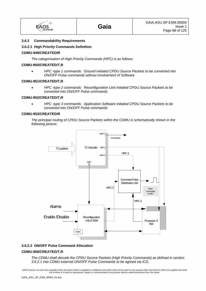
Gaia
GAIA.ASU.SP.ESM.00004Issue 1
Page 68 of 125
EADS Astrium Ltd owns the copyright of this document which is supplied in confidence and which shall not be used for any purpose other than that for which it is supplied and shall not in whole or in part be reproduced, copied, or communicated to any person without written permission from the owner.
GAIA_ASU_SP_ESM_00004_01.doc
3.6.2 Commandability Requirements
3.6.2.1 High Priority Commands Definition
CDMU-949/CREATED/R
The categorisation of High Priority Commands (HPC) is as follows:
CDMU-950/CREATED/T,R
• HPC -type 1 commands: Ground initiated CPDU Source Packets to be converted into ON/OFF Pulse commands without involvement of Software
CDMU-951/CREATED/T,R
• HPC -type 2 commands: Reconfiguration Unit initiated CPDU Source Packets to be converted into ON/OFF Pulse commands
CDMU-952/CREATED/T,R
• HPC -type 3 commands: Application Software initiated CPDU Source Packets to be converted into ON/OFF Pulse commands
CDMU-953/CREATED/R
The principal routing of CPDU Source Packets within the CDMU is schematically shown in the following picture:
Enable /Disable
TC Decoder
Processor ASW
ReconfigurationUnit & SGM
TC packets
MAP 2
MAP32
Alarms
MAP 0
EDAC
MAP 1
PulseCommands
to HW
not assigned
HPC-3
HPC-1
HPC-2
Command PulseDistribution Unit
3.6.2.2 ON/OFF Pulse Command Allocation
CDMU-956/CREATED/T,R
The CDMU shall decode the CPDU Source Packets (High Priority Commands) as defined in section 3.6.2.1 into CDMU external ON/OFF Pulse Commands to be agreed via ICD.
Gaia
GAIA.ASU.SP.ESM.00004Issue 1
Page 69 of 125
EADS Astrium Ltd owns the copyright of this document which is supplied in confidence and which shall not be used for any purpose other than that for which it is supplied and shall not in whole or in part be reproduced, copied, or communicated to any person without written permission from the owner.
GAIA_ASU_SP_ESM_00004_01.doc
Note: a typical external ON/OFF pulse command allocation is given in annex II( to be added).
CDMU-957/CREATED/R
The subcontractor shall define the allocation of CPDU Source Packets (High Priority Commands) for the required CDMU internal ON/OFF Pulse Commands.
3.6.2.3 Support of Reconfiguration for Safe Mode
CDMU-959/CREATED/T,R
The CDMU shall support the satellite Safe Mode. In this mode, spacecraft telemetry shall be available which allows ground to assess the spacecraft status and define recovery actions. This may be a subset of the nominal telemetry acquired via independent acquisition and formatting stages
CDMU-960/CREATED/T,R
It shall be possible to start the execution of the safe mode software located in a protected memory area.
CDMU-961/CREATED/T,A
The time between a Safe Mode alarm input to the CDMU and the start of the Safe Mode APSW shall not exceed 20 sec. This time shall include the processor reconfiguration time as defined in section 3.2.4.2 and the time required to achieve the operational state of all pre-selected CDMU modules.
CDMU-962/CREATED/T,R
For Safe Mode, the CDMU shall support a switch-over to the redundant processor and usage of dedicated equipment as defined in a non-volatile memory area.
CDMU-963/CREATED/T,A
It shall be possible to start transition to safe mode initiated by a cold reset command. The branching to Safe Mode shall occur during start-up depending on a parameter stored in a non-volatile memory (refer also to section 3.5.1 , Start-Up Software).
3.7 Failure Detection, Isolation and Recovery (FDIR) Requirements
CDMU-965/CREATED/T,A
The CDMU shall support the on-board Failure Detection, Isolation and Recovery (FDIR) functions.
CDMU-966/CREATED/T,A
One of the FDIR functions shall be the Automatic Reconfiguration Sequence Generation Function, i.e. the usage of redundant resources.
CDMU-967/CREATED/A
CDMU internal mission critical functions shall be identified and shall be agreed with the customer.
CDMU-968/CREATED/T,A
CDMU internal mission critical functions shall be observable by at least two independently obtained measurements.
CDMU-969/CREATED/T,A
It shall be possible for the ground to enable / disable and override each individual fault management function. This shall be possible parameter by parameter. In the case of automatic functions without this capability details shall be provided to the customer and ESA for approval.
CDMU-970/CREATED/T,A
The CDMU shall provide Failure Detection, Isolation and Recovery facilities of its own proper functioning. Appropriate hardware (by the Reconfiguration Units) and software (by specific SW functions to be provided by the API, SUSW & Application S/W) provisions shall be included into the design to automatically detect anomalies during flight and initiate the activation of corresponding redundant elements.
Gaia
GAIA.ASU.SP.ESM.00004Issue 1
Page 70 of 125
EADS Astrium Ltd owns the copyright of this document which is supplied in confidence and which shall not be used for any purpose other than that for which it is supplied and shall not in whole or in part be reproduced, copied, or communicated to any person without written permission from the owner.
GAIA_ASU_SP_ESM_00004_01.doc
CDMU-971/CREATED/T,A
The CDMU shall include adequate alarm conditioning functions to identify software lockouts at the level of HW/ SW interfaces.
CDMU-972/CREATED/T,A
The CDMU shall provide a watchdog timer function to detect software lockout situations.
CDMU-973/CREATED/T,A
The CDMU shall provide access to all processor registers and memories such to allow ground to assess the CDMU health status.
Gaia
GAIA.ASU.SP.ESM.00004Issue 1
Page 71 of 125
EADS Astrium Ltd owns the copyright of this document which is supplied in confidence and which shall not be used for any purpose other than that for which it is supplied and shall not in whole or in part be reproduced, copied, or communicated to any person without written permission from the owner.
GAIA_ASU_SP_ESM_00004_01.doc
4 CDMU SPECIFIC DESIGN AND INTERFACE REQUIREMENTS
4.1 Mechanical Design and Interface Requirements
4.1.1 Mass
CDMU-980/CREATED/T,A,I
The CDMU mass in flight configuration shall be less than 11.5 Kg. This shall be verified by mass measurement on the fully assembled unit.
4.1.2 Centre of Gravity
CDMU-982/CREATED/T,A,I
The [AD 2], section 3.2.1.3 is applicable.
4.1.3 Envelope
CDMU-984/CREATED/I,R
The unit including mounting feet and connectors shall not exceed the dimensions:
X x Y x Z: tbd mm x tbd mm x tbd mm
This shall be verified by dimension measurements.
4.2 Thermal Design and Interface Requirements
4.2.1 Heat Dissipation
CDMU-987/CREATED/T,A
Depending on the operational status, the unit dissipation shall not exceed the following range:
Average* : 34W mean
*: Average power is defined by:
• the CDMU being in Nominal Mode,
• sending TM on X-Band,
• transmitting 25% of the time on the external MIL-1553 buses
• transmitting 50% on the Spacewire Science data link with a data rate of 5Mbps.
• no other external I/O activity
4.2.2 CDMU Thermal Properties
CDMU-989/CREATED/T,A
[AD 2] section 3.3 is applicable.
CDMU-2349/CREATED/T,A
The CDMU thermal design shall ensure that the EEPROM case temperature does not exceed 55 C under any operating condition. See technical note [AD 9], section 4.2
CDMU-3419/ERS_701,GDI-2583/A,R
The unit thermal design shall consider a heat sink all around the unit (on 4 PI steradian) with temperature range defined in [AD 2]/GDI-2583.
CDMU-3420/ERS_702/A,R
The unit thermal design shall consider a maximum thermal conductance of 0.015 W/K at each unit fixation foot (e.g commensurate with insulation through GFRP washers).
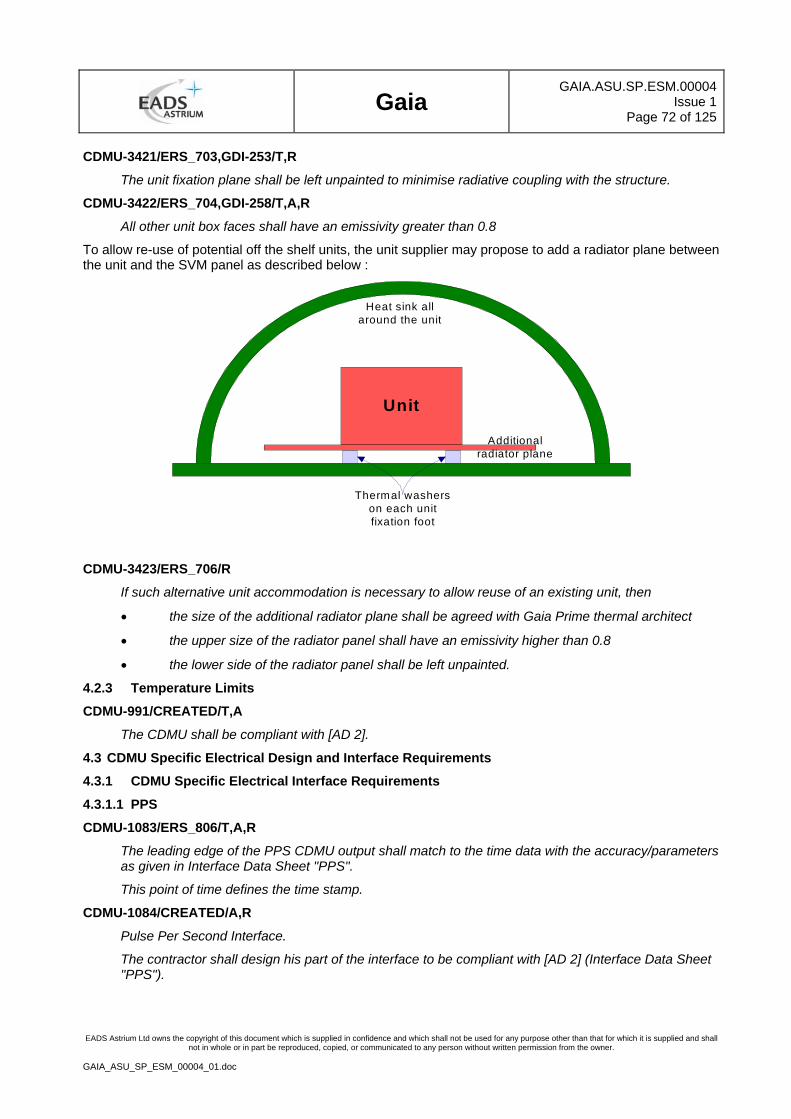
Gaia
GAIA.ASU.SP.ESM.00004Issue 1
Page 72 of 125
EADS Astrium Ltd owns the copyright of this document which is supplied in confidence and which shall not be used for any purpose other than that for which it is supplied and shall not in whole or in part be reproduced, copied, or communicated to any person without written permission from the owner.
GAIA_ASU_SP_ESM_00004_01.doc
CDMU-3421/ERS_703,GDI-253/T,R
The unit fixation plane shall be left unpainted to minimise radiative coupling with the structure.
CDMU-3422/ERS_704,GDI-258/T,A,R
All other unit box faces shall have an emissivity greater than 0.8
To allow re-use of potential off the shelf units, the unit supplier may propose to add a radiator plane between the unit and the SVM panel as described below :
Heat sink allaround the unit
Unit
Thermal washerson each unitfixation foot
Additionalradiator plane
CDMU-3423/ERS_706/R
If such alternative unit accommodation is necessary to allow reuse of an existing unit, then
• the size of the additional radiator plane shall be agreed with Gaia Prime thermal architect
• the upper size of the radiator panel shall have an emissivity higher than 0.8
• the lower side of the radiator panel shall be left unpainted.
4.2.3 Temperature Limits
CDMU-991/CREATED/T,A
The CDMU shall be compliant with [AD 2].
4.3 CDMU Specific Electrical Design and Interface Requirements
4.3.1 CDMU Specific Electrical Interface Requirements
4.3.1.1 PPS
CDMU-1083/ERS_806/T,A,R
The leading edge of the PPS CDMU output shall match to the time data with the accuracy/parameters as given in Interface Data Sheet "PPS".
This point of time defines the time stamp.
CDMU-1084/CREATED/A,R
Pulse Per Second Interface.
The contractor shall design his part of the interface to be compliant with [AD 2] (Interface Data Sheet "PPS").
Gaia
GAIA.ASU.SP.ESM.00004Issue 1
Page 73 of 125
EADS Astrium Ltd owns the copyright of this document which is supplied in confidence and which shall not be used for any purpose other than that for which it is supplied and shall not in whole or in part be reproduced, copied, or communicated to any person without written permission from the owner.
GAIA_ASU_SP_ESM_00004_01.doc
4.3.1.2 2PPS Interface
CDMU-1088/CREATED/T,A,R
The leading edge of the 2PPS (2 Hz Sync.) signal shall match to the time data with the accuracy/parameters as given in Interface Data Sheet "PPS", but with a frequency of 2Hz.
This point of time defines the time stamp.
CDMU-1089/CREATED/A,R
2PPS Interface.
The contractor shall design his part of the interface to be compliant with [AD 2] (Interface Data Sheet "PPS"):
4.3.1.3 8PPS Interface
CDMU-1093/CREATED/A,R
8PPS Interface.
The contractor shall design his part of the interface to be compliant with [AD 2] (Interface Data Sheet "PPS"):
CDMU-1094/CREATED/T,R
The leading edge of the 8PPS (8 Hz Sync.) signal shall match to the time data with the accuracy/parameters as given in Interface Data Sheet "PPS", but with a frequency of 8Hz.
This point of time defines the time stamp.
4.3.1.4 1Hz Synchronisation Pulse Interface (1SY)
CDMU-1098/CREATED/T,R
The leading edge of the 1 Hz Synchronisation Pulse (CDMU Input) shall match to the time data with the accuracy/parameters as given in Interface Data Sheet "1SY".
CDMU-1099/CREATED/R
1 Hz Synchronisation Interface.
The contractor shall design his part of the interface to be compliant with [AD 2] (Interface Data Sheet "PPS"):
4.3.1.5 TFG Time Strobe Interface
CDMU-1102/CREATED/R
TFG Time Strobe Interface.
The contractor shall design his part of the interface to be compliant to the following characteristics (Interface Data Sheet "PPS"Time Strobe"):
4.3.1.6 Alarm Input Channel Interface
CDMU-1106/ERS_870/T,R
Each external Alarm Interface shall be configurable either as differential type (Interface Data Sheet "SAD") or as single ended/switch-closure type (Interface Data Sheet "SAC"). Configuration shall be done during manufacturing).
CDMU-1107/ERS_870/A,R
The contractor shall design his part of the differential type System Alarm interface to be compliant to the following characteristics (Interface Data Sheet "SAD"):
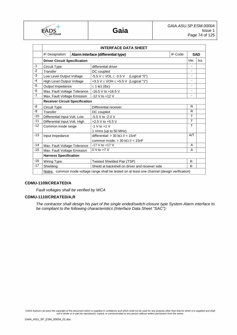
Gaia
GAIA.ASU.SP.ESM.00004Issue 1
Page 74 of 125
EADS Astrium Ltd owns the copyright of this document which is supplied in confidence and which shall not be used for any purpose other than that for which it is supplied and shall not in whole or in part be reproduced, copied, or communicated to any person without written permission from the owner.
GAIA_ASU_SP_ESM_00004_01.doc
INTERFACE DATA SHEET IF Designation: Alarm Interface (differential type) IF-Code: SAD Driver Circuit Specification Ver. Iss. -1 Circuit Type differential driver - -2 Transfer DC coupled - -3 Low Level Output Voltage -5.5 V ≤ VOL ≤ -3.5 V (Logical "0") - -4 High Level Output Voltage +3.5 V ≤ VOH ≤ +5.5 V (Logical "1") - -5 Output Impedance ≤ 1 kΩ (tbc) - -6 Max. Fault Voltage Tolerance -16.5 V to +16.5 V - -7 Max. Fault Voltage Emission -12 V to +12 V -
Receiver Circuit Specification -8 Circuit Type Differential receiver R -9 Transfer DC coupled R -10 Differential Input Volt. Low -5.5 V to -2.0 V T -11 Differential Input Volt. High +2.5 V to +5.5 V T -12 Common mode range -1 V to +1 V
1 Vrms (up to 50 MHz) T
-13 Input Impedance differential: > 30 kΩ // < 15nF common mode: > 30 kΩ // < 15nF
A/T
-14 Max. Fault Voltage Tolerance -17 V to +17 V A -15 Max. Fault Voltage Emission 0 V to +7 V A Harness Specification -16 Wiring Type: Twisted Shielded Pair (TSP) R -17 Shielding: Shield at backshell on driver and receiver side R Notes: common mode voltage range shall be tested on at least one channel (design verification)
CDMU-1109/CREATED/A
Fault voltages shall be verified by WCA
CDMU-1110/CREATED/A,R
The contractor shall design his part of the single ended/switch-closure type System Alarm interface to be compliant to the following characteristics (Interface Data Sheet "SAC"):
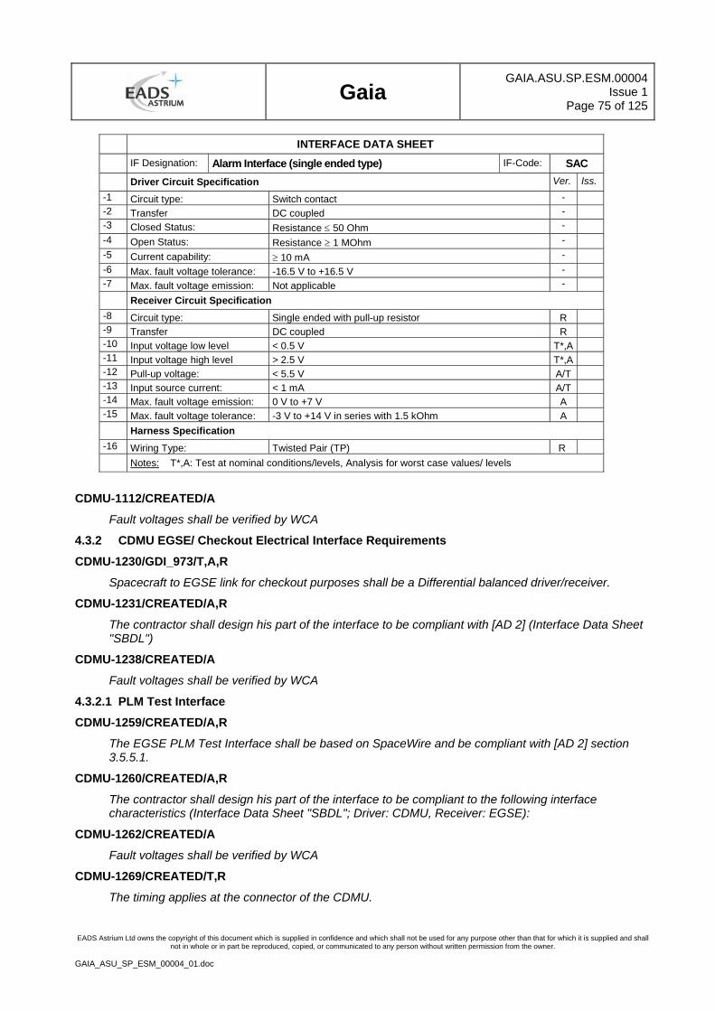
Gaia
GAIA.ASU.SP.ESM.00004Issue 1
Page 75 of 125
EADS Astrium Ltd owns the copyright of this document which is supplied in confidence and which shall not be used for any purpose other than that for which it is supplied and shall not in whole or in part be reproduced, copied, or communicated to any person without written permission from the owner.
GAIA_ASU_SP_ESM_00004_01.doc
INTERFACE DATA SHEET IF Designation: Alarm Interface (single ended type) IF-Code: SAC Driver Circuit Specification Ver. Iss. -1 Circuit type: Switch contact - -2 Transfer DC coupled - -3 Closed Status: Resistance ≤ 50 Ohm - -4 Open Status: Resistance ≥ 1 MOhm - -5 Current capability: ≥ 10 mA - -6 Max. fault voltage tolerance: -16.5 V to +16.5 V - -7 Max. fault voltage emission: Not applicable -
Receiver Circuit Specification -8 Circuit type: Single ended with pull-up resistor R -9 Transfer DC coupled R -10 Input voltage low level < 0.5 V T*,A -11 Input voltage high level > 2.5 V T*,A -12 Pull-up voltage: < 5.5 V A/T -13 Input source current: < 1 mA A/T -14 Max. fault voltage emission: 0 V to +7 V A -15 Max. fault voltage tolerance: -3 V to +14 V in series with 1.5 kOhm A Harness Specification -16 Wiring Type: Twisted Pair (TP) R Notes: T*,A: Test at nominal conditions/levels, Analysis for worst case values/ levels
CDMU-1112/CREATED/A
Fault voltages shall be verified by WCA
4.3.2 CDMU EGSE/ Checkout Electrical Interface Requirements
CDMU-1230/GDI_973/T,A,R
Spacecraft to EGSE link for checkout purposes shall be a Differential balanced driver/receiver.
CDMU-1231/CREATED/A,R
The contractor shall design his part of the interface to be compliant with [AD 2] (Interface Data Sheet "SBDL")
CDMU-1238/CREATED/A
Fault voltages shall be verified by WCA
4.3.2.1 PLM Test Interface
CDMU-1259/CREATED/A,R
The EGSE PLM Test Interface shall be based on SpaceWire and be compliant with [AD 2] section 3.5.5.1.
CDMU-1260/CREATED/A,R
The contractor shall design his part of the interface to be compliant to the following interface characteristics (Interface Data Sheet "SBDL"; Driver: CDMU, Receiver: EGSE):
CDMU-1262/CREATED/A
Fault voltages shall be verified by WCA
CDMU-1269/CREATED/T,R
The timing applies at the connector of the CDMU.
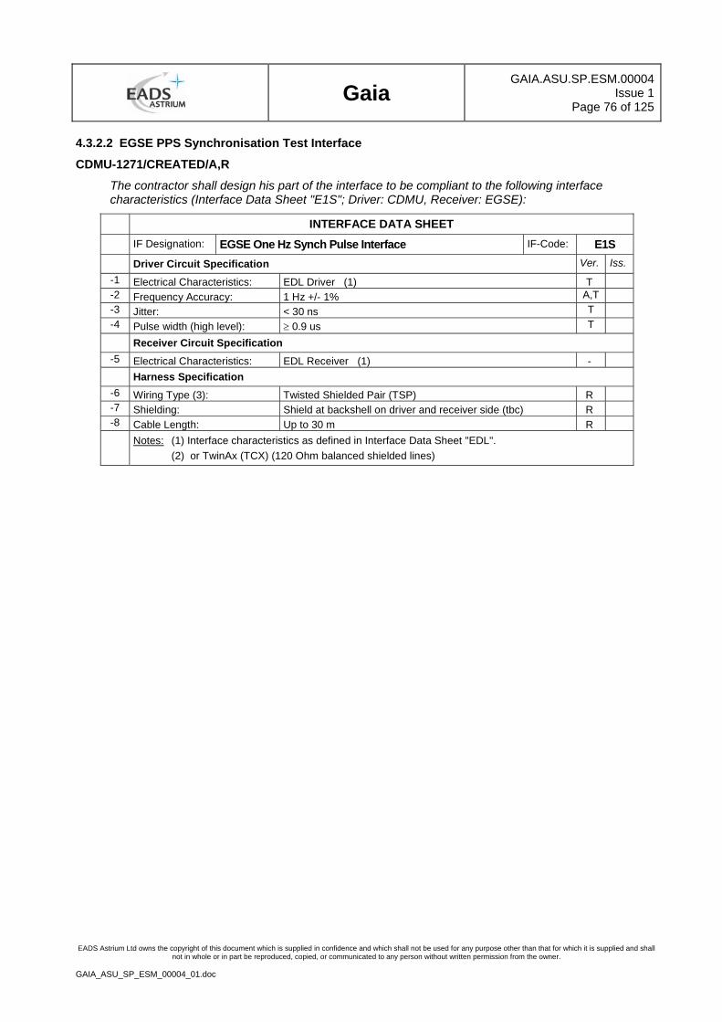
Gaia
GAIA.ASU.SP.ESM.00004Issue 1
Page 76 of 125
EADS Astrium Ltd owns the copyright of this document which is supplied in confidence and which shall not be used for any purpose other than that for which it is supplied and shall not in whole or in part be reproduced, copied, or communicated to any person without written permission from the owner.
GAIA_ASU_SP_ESM_00004_01.doc
4.3.2.2 EGSE PPS Synchronisation Test Interface
CDMU-1271/CREATED/A,R
The contractor shall design his part of the interface to be compliant to the following interface characteristics (Interface Data Sheet "E1S"; Driver: CDMU, Receiver: EGSE):
INTERFACE DATA SHEET IF Designation: EGSE One Hz Synch Pulse Interface IF-Code: E1S Driver Circuit Specification Ver. Iss.
-1 Electrical Characteristics: EDL Driver (1) T -2 Frequency Accuracy: 1 Hz +/- 1% A,T -3 Jitter: < 30 ns T -4 Pulse width (high level): ≥ 0.9 us T
Receiver Circuit Specification -5 Electrical Characteristics: EDL Receiver (1) - Harness Specification
-6 Wiring Type (3): Twisted Shielded Pair (TSP) R -7 Shielding: Shield at backshell on driver and receiver side (tbc) R -8 Cable Length: Up to 30 m R
Notes: (1) Interface characteristics as defined in Interface Data Sheet "EDL". (2) or TwinAx (TCX) (120 Ohm balanced shielded lines)
Gaia
GAIA.ASU.SP.ESM.00004Issue 1
Page 77 of 125
EADS Astrium Ltd owns the copyright of this document which is supplied in confidence and which shall not be used for any purpose other than that for which it is supplied and shall not in whole or in part be reproduced, copied, or communicated to any person without written permission from the owner.
GAIA_ASU_SP_ESM_00004_01.doc
5 GENERAL DESIGN AND INTERFACE REQUIREMENTS
5.1 GDIR Applicability
CDMU-2313/CREATED/T,A
The CDMU shall comply with section 8 ( GDIR Applicable Matrix) of this document.
5.2 CDMU RAM Specific Requirements
5.2.1 Reliability
CDMU-1285/ERS_417,ERS_32,ERS_643/A,R
The CDMU design shall achieve a reliability of 0.99 (tbc) taking into account the periods for
• on-ground testing and storage as defined in [AD 2].
• in-orbit operation of 60 months as defined in [AD 2].
5.2.2 Availability
CDMU-1287/CREATED/A
If a scrubbing function shall be implemented to fulfil the availability requirements due to radiation environmental conditions, the following design rules shall be fulfilled:
• No functional unavailability of the CDMU shall be caused by the scrubbing function
• The period of the scrubbing function shall be defined according to the availability requirements due to radiation event
• Any scrubber function period setting shall be flight-modifiable.
CDMU-1288/CREATED/A
The CDMU hardware shall allow to elaborate at power-up CDMU BIT with a test coverage better than 95%.
CDMU-1289/CREATED/A
The CDMU hardware shall allow to elaborate an on line CDMU BIT with a test coverage better than 90%.
CDMU-1290/CREATED/A
All on-line CDMU individual tests shall provide capabilities to be enabled, disabled, executed and monitored by the CDMU Application Software.
CDMU-1291/CREATED/T,A
The detection of any failure during tests shall be reported to the CDMU Application Software.
5.2.3 Maintainability
CDMU-1293/CREATED/R
The design shall ensure a minimum effort for maintainability (with minimum need for special tools (if any), equipment calibration, adjustment or fault identification). Maintenance shall have no impact on the system performance and interfaces and has to be documented in a special procedure.
CDMU-3424/CREATED/R
On the CDMU breadboard (BB) model, the PROM shall be on a socket, allowing a new PROM is necessary (due to software update). On EM/EQM/PFM, the PROM shall be soldered.
5.2.4 CDMU Fault Tolerance Requirements
CDMU-1295/CREATED/A
The CDMU shall be single point failure (SPF) free.
Gaia
GAIA.ASU.SP.ESM.00004Issue 1
Page 78 of 125
EADS Astrium Ltd owns the copyright of this document which is supplied in confidence and which shall not be used for any purpose other than that for which it is supplied and shall not in whole or in part be reproduced, copied, or communicated to any person without written permission from the owner.
GAIA_ASU_SP_ESM_00004_01.doc
CDMU-1296/CREATED/A
No single failure inside the CDMU shall cause permanent loss of function or performance of the CDMU. Full function and performance shall be reobtained by activation of the redundancy.
CDMU-1297/CREATED/A
No single failure inside the CDMU shall cause inadvertent activation of outputs or automatic reconfiguration sequences.
CDMU-1298/CREATED/A
No single failure shall cause the loss of the nominal and the redundant part of CDMU functions.
CDMU-1299/CREATED/A
No single failure, neither SEU nor firmware caused errors, shall lead to the occurrence of the following feared events:
• ER01: no Processor Module active
• ER02: both Processor Module simultaneously in active mode
• ER03: active Processor Module permanently blocked in RESET mode
• ER04: active Processor Module blocked and Watchdog inhibited
• ER05: operational degradation of more than one Mil-1553B bus
• ER06: warm-up BIT permanently active, not allowing the transition to Processor Module active mode
• ER07: on-line BIT permanently freezing any Processor Module activity
• ER08: inadvertent modification of the “enable/inhibit alarm” status of the RU
• ER09: RU permanently in program mode
• ER10: inadvertent or erroneous HPC-type 1
• ER11: inadvertent modification of EEPROM contents
• ER12: simultaneous loss of the RU function and of the active Processor Module
• ER13: simultaneous loss of the RU function and of the non-active Processor Module
• ER14: both TIF simultaneously in active mode
• ER15: permanent RF switch command
• ER16: both Processor Module simultaneously in Service Mode
CDMU-1300/CREATED/A
A single failure in the nominal DC/DC Converter, Command Decoder, Processor Module, Transfer Frame Generator, Reconfiguration Unit or Mass Memory Unit shall not result in the loss or degradation of the corresponding redundant function.
CDMU-1301/CREATED/A
A single failure in the nominal Command Decoder, Processor Module, Transfer Frame Generator, Reconfiguration Unit or Mass Memory Unit shall not affect the cross-strapping of the redundant module to any other module.
CDMU-1302/CREATED/A
Any single failure in the CDMU power distribution shall not lead to a loss of both telecommand decoder.
Gaia
GAIA.ASU.SP.ESM.00004Issue 1
Page 79 of 125
EADS Astrium Ltd owns the copyright of this document which is supplied in confidence and which shall not be used for any purpose other than that for which it is supplied and shall not in whole or in part be reproduced, copied, or communicated to any person without written permission from the owner.
GAIA_ASU_SP_ESM_00004_01.doc
CDMU-1303/CREATED/A
The telecommand decoder power supply shall be SEU tolerant.
CDMU-1304/CREATED/T,A
Redundancy shall be incorporated at all levels where required to eliminate critical failure and to meet the required fault tolerance.
CDMU-1305/CREATED/A,R
Implementation of mutually redundant functions on the same board shall be avoided to prevent propagation of failures.
5.3 Design Rules
CDMU-1307/CREATED/I,R
The redundant parts of CDMU functions shall be physically separated.
CDMU-1308/CREATED/A,R
The CDMU shall implement as a minimum for each part of redundant functions temperature and DC/DC converter secondary voltage measurements.
CDMU-1310/CREATED/T,A
Each DC/DC converter of CDMU function shall implement protection against over voltage of secondary power.
5.4 Identification & Marking
CDMU-1312/CREATED/I,R
A nameplate shall mark the unit hardware in order to achieve configuration traceability.
CDMU-2312/CREATED/I,R
The CDMU identification shall be made in accordance with the requirements of [AD 2].
CDMU-2298/CREATED/I,R
The CDMU container shall be identified as per [AD 2].
5.5 Unit Packing
CDMU-2306/CREATED/R
The CDMU shall be packed prior to transportation as per [AD 2].
5.6 Handling
CDMU-2307/CREATED/R
The CDMU shall be handled as per [AD 2].
5.7 Mass
CDMU-2308/CREATED/T,R
The CDMU shall be subjected to Mass Properties as per [AD 2].
5.8 COG/M.I.
CDMU-2310/CREATED/T,A
The CDMU shall have the centre of Gravity and the Moment of Inertia measured as per [AD 2].
Gaia
GAIA.ASU.SP.ESM.00004Issue 1
Page 80 of 125
EADS Astrium Ltd owns the copyright of this document which is supplied in confidence and which shall not be used for any purpose other than that for which it is supplied and shall not in whole or in part be reproduced, copied, or communicated to any person without written permission from the owner.
GAIA_ASU_SP_ESM_00004_01.doc
6 PRODUCT ASSURANCE REQUIREMENTS
CDMU-1314/CREATED/R
The Product Assurance Requirements for Subcontractors [AD 8] are applicable.
CDMU-1315/CREATED/R
The Software Product Assurance Requirements for Subcontractors[AD 3] are applicable.
Gaia
GAIA.ASU.SP.ESM.00004Issue 1
Page 81 of 125
EADS Astrium Ltd owns the copyright of this document which is supplied in confidence and which shall not be used for any purpose other than that for which it is supplied and shall not in whole or in part be reproduced, copied, or communicated to any person without written permission from the owner.
GAIA_ASU_SP_ESM_00004_01.doc
7 VERIFICATION REQUIREMENTS
7.1 Required CDMU Level Tests
7.1.1 Functional/ Performance Tests
CDMU-1321/CREATED/R
Functional and performance parameters derived from above requirements shall be measured/ verified under relevant boundary conditions.
CDMU-1322/CREATED/R
The subcontractor shall demonstrate by means of functional and performance tests that there is no degradation caused by environmental testing.
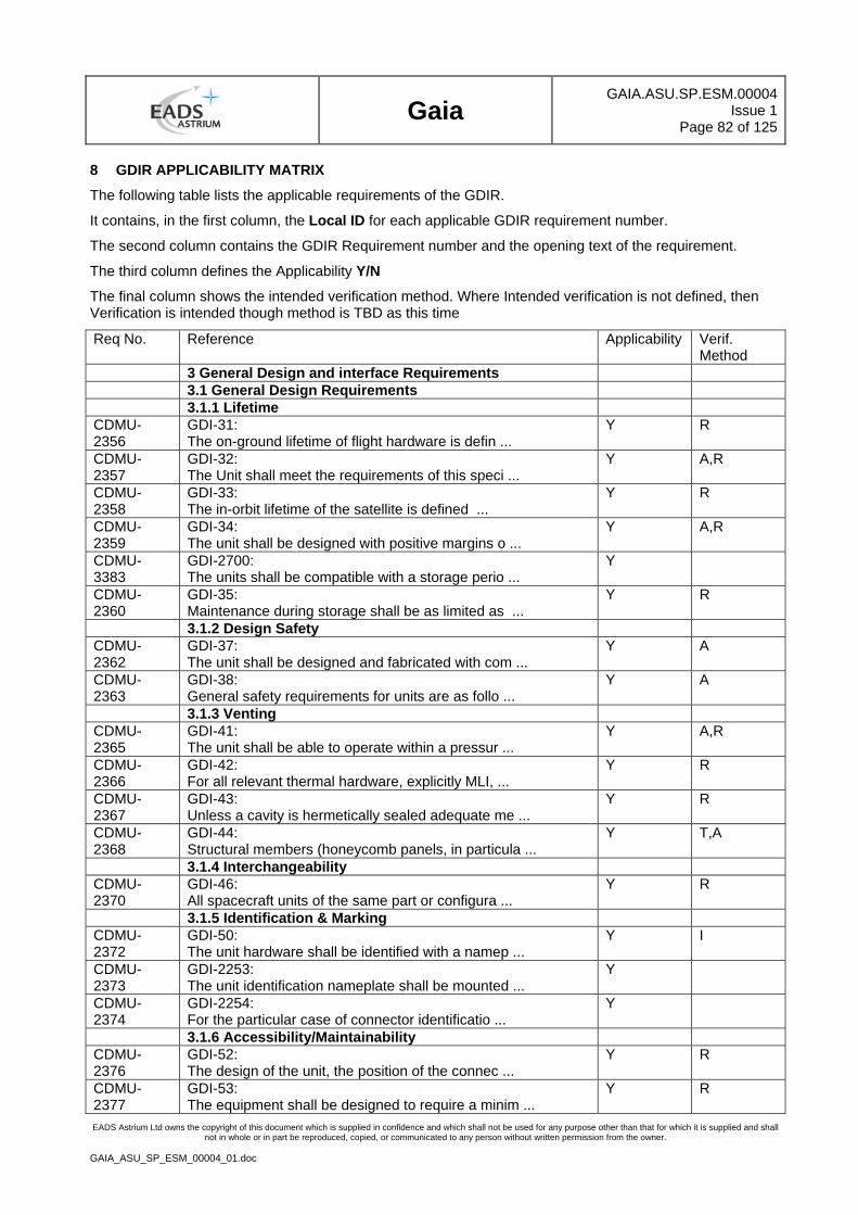
Gaia
GAIA.ASU.SP.ESM.00004Issue 1
Page 82 of 125
EADS Astrium Ltd owns the copyright of this document which is supplied in confidence and which shall not be used for any purpose other than that for which it is supplied and shall not in whole or in part be reproduced, copied, or communicated to any person without written permission from the owner.
GAIA_ASU_SP_ESM_00004_01.doc
8 GDIR APPLICABILITY MATRIX
The following table lists the applicable requirements of the GDIR.
It contains, in the first column, the Local ID for each applicable GDIR requirement number.
The second column contains the GDIR Requirement number and the opening text of the requirement.
The third column defines the Applicability Y/N
The final column shows the intended verification method. Where Intended verification is not defined, then Verification is intended though method is TBD as this time
Req No. Reference Applicability Verif. Method
3 General Design and interface Requirements 3.1 General Design Requirements 3.1.1 Lifetime CDMU-2356
GDI-31: The on-ground lifetime of flight hardware is defin ...
Y R
CDMU-2357
GDI-32: The Unit shall meet the requirements of this speci ...
Y A,R
CDMU-2358
GDI-33: The in-orbit lifetime of the satellite is defined ...
Y R
CDMU-2359
GDI-34: The unit shall be designed with positive margins o ...
Y A,R
CDMU-3383
GDI-2700: The units shall be compatible with a storage perio ...
Y
CDMU-2360
GDI-35: Maintenance during storage shall be as limited as ...
Y R
3.1.2 Design Safety CDMU-2362
GDI-37: The unit shall be designed and fabricated with com ...
Y A
CDMU-2363
GDI-38: General safety requirements for units are as follo ...
Y A
3.1.3 Venting CDMU-2365
GDI-41: The unit shall be able to operate within a pressur ...
Y A,R
CDMU-2366
GDI-42: For all relevant thermal hardware, explicitly MLI, ...
Y R
CDMU-2367
GDI-43: Unless a cavity is hermetically sealed adequate me ...
Y R
CDMU-2368
GDI-44: Structural members (honeycomb panels, in particula ...
Y T,A
3.1.4 Interchangeability CDMU-2370
GDI-46: All spacecraft units of the same part or configura ...
Y R
3.1.5 Identification & Marking CDMU-2372
GDI-50: The unit hardware shall be identified with a namep ...
Y I
CDMU-2373
GDI-2253: The unit identification nameplate shall be mounted ...
Y
CDMU-2374
GDI-2254: For the particular case of connector identificatio ...
Y
3.1.6 Accessibility/Maintainability CDMU-2376
GDI-52: The design of the unit, the position of the connec ...
Y R
CDMU-2377
GDI-53: The equipment shall be designed to require a minim ...
Y R
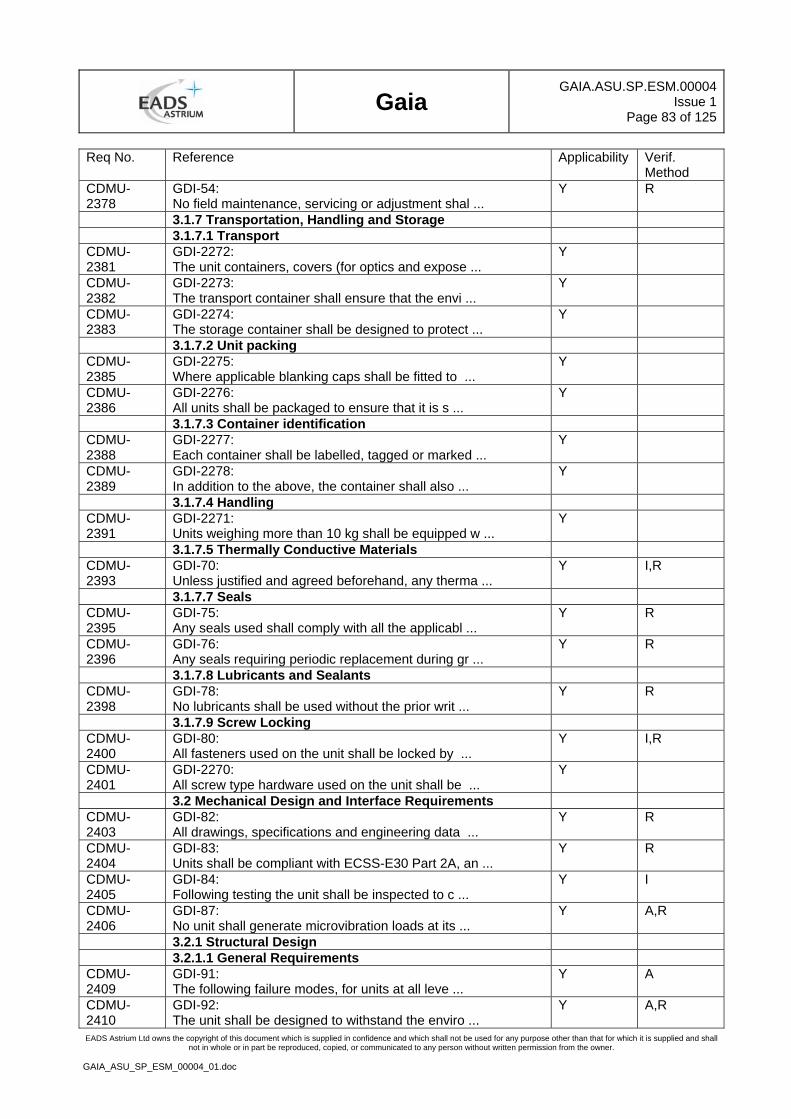
Gaia
GAIA.ASU.SP.ESM.00004Issue 1
Page 83 of 125
EADS Astrium Ltd owns the copyright of this document which is supplied in confidence and which shall not be used for any purpose other than that for which it is supplied and shall not in whole or in part be reproduced, copied, or communicated to any person without written permission from the owner.
GAIA_ASU_SP_ESM_00004_01.doc
Req No. Reference Applicability Verif. Method
CDMU-2378
GDI-54: No field maintenance, servicing or adjustment shal ...
Y R
3.1.7 Transportation, Handling and Storage 3.1.7.1 Transport CDMU-2381
GDI-2272: The unit containers, covers (for optics and expose ...
Y
CDMU-2382
GDI-2273: The transport container shall ensure that the envi ...
Y
CDMU-2383
GDI-2274: The storage container shall be designed to protect ...
Y
3.1.7.2 Unit packing CDMU-2385
GDI-2275: Where applicable blanking caps shall be fitted to ...
Y
CDMU-2386
GDI-2276: All units shall be packaged to ensure that it is s ...
Y
3.1.7.3 Container identification CDMU-2388
GDI-2277: Each container shall be labelled, tagged or marked ...
Y
CDMU-2389
GDI-2278: In addition to the above, the container shall also ...
Y
3.1.7.4 Handling CDMU-2391
GDI-2271: Units weighing more than 10 kg shall be equipped w ...
Y
3.1.7.5 Thermally Conductive Materials CDMU-2393
GDI-70: Unless justified and agreed beforehand, any therma ...
Y I,R
3.1.7.7 Seals CDMU-2395
GDI-75: Any seals used shall comply with all the applicabl ...
Y R
CDMU-2396
GDI-76: Any seals requiring periodic replacement during gr ...
Y R
3.1.7.8 Lubricants and Sealants CDMU-2398
GDI-78: No lubricants shall be used without the prior writ ...
Y R
3.1.7.9 Screw Locking CDMU-2400
GDI-80: All fasteners used on the unit shall be locked by ...
Y I,R
CDMU-2401
GDI-2270: All screw type hardware used on the unit shall be ...
Y
3.2 Mechanical Design and Interface Requirements CDMU-2403
GDI-82: All drawings, specifications and engineering data ...
Y R
CDMU-2404
GDI-83: Units shall be compliant with ECSS-E30 Part 2A, an ...
Y R
CDMU-2405
GDI-84: Following testing the unit shall be inspected to c ...
Y I
CDMU-2406
GDI-87: No unit shall generate microvibration loads at its ...
Y A,R
3.2.1 Structural Design 3.2.1.1 General Requirements CDMU-2409
GDI-91: The following failure modes, for units at all leve ...
Y A
CDMU-2410
GDI-92: The unit shall be designed to withstand the enviro ...
Y A,R
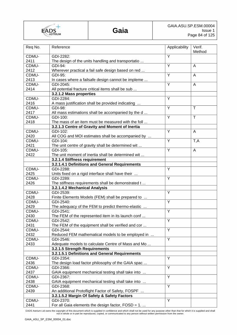
Gaia
GAIA.ASU.SP.ESM.00004Issue 1
Page 84 of 125
EADS Astrium Ltd owns the copyright of this document which is supplied in confidence and which shall not be used for any purpose other than that for which it is supplied and shall not in whole or in part be reproduced, copied, or communicated to any person without written permission from the owner.
GAIA_ASU_SP_ESM_00004_01.doc
Req No. Reference Applicability Verif. Method
CDMU-2411
GDI-2282: The design of the units handling and transportatio ...
Y
CDMU-2412
GDI-94: Wherever practical a fail safe design based on red ...
Y A
CDMU-2413
GDI-95: In cases where a failsafe design cannot be impleme ...
Y A
CDMU-2414
GDI-2045: All potential fracture critical items shall be sub ...
Y A
3.2.1.2 Mass properties CDMU-2416
GDI-2284: A mass justification shall be provided indicating ...
Y
CDMU-2417
GDI-98: All mass estimations shall be accompanied by the d ...
Y T
CDMU-2418
GDI-100: The mass of an item must be measured with the foll ...
Y T
3.2.1.3 Centre of Gravity and Moment of Inertia CDMU-2420
GDI-102: All COG and MOI estimates shall be accompanied by ...
Y A
CDMU-2421
GDI-104: The unit centre of gravity shall be determined wit ...
Y T,A
CDMU-2422
GDI-105: The unit moment of inertia shall be determined wit ...
Y A
3.2.1.4 Stiffness requirement 3.2.1.4.1 Definitions and General Requirements CDMU-2425
GDI-2288: Units fixed on a rigid interface shall have their ...
Y
CDMU-2426
GDI-2289: The stiffness requirements shall be demonstrated t ...
Y
3.2.1.4.2 Mechanical Analysis CDMU-2428
GDI-2539: Finite Elements Models (FEM) shall be prepared to ...
Y
CDMU-2429
GDI-2540: The adequacy of the FEM to predict thermo-elastic ...
Y
CDMU-2430
GDI-2541: The FEM of the represented item in its launch conf ...
Y
CDMU-2431
GDI-2542: The FEM of the equipment shall be verified and cor ...
Y
CDMU-2432
GDI-2544: Reduced FEM mathematical models to be employed in ...
Y
CDMU-2433
GDI-2546: Adequate models to calculate Centre of Mass and Mo ...
Y
3.2.1.5 Strength Requirements 3.2.1.5.1 Definitions and General Requirements CDMU-2436
GDI-2354: The design load factor philosophy of the GAIA spac ...
Y
CDMU-2437
GDI-2366: GAIA equipment mechanical testing shall take into ...
Y
CDMU-2438
GDI-2367: GAIA equipment mechanical testing shall take into ...
Y
CDMU-2439
GDI-2368: An additional Protoflight Factor of Safety, FOSPF ...
Y
3.2.1.5.2 Margin Of Safety & Safety Factors CDMU-2441
GDI-2370: For all Gaia elements the design factor, FOSD = 1. ...
Y
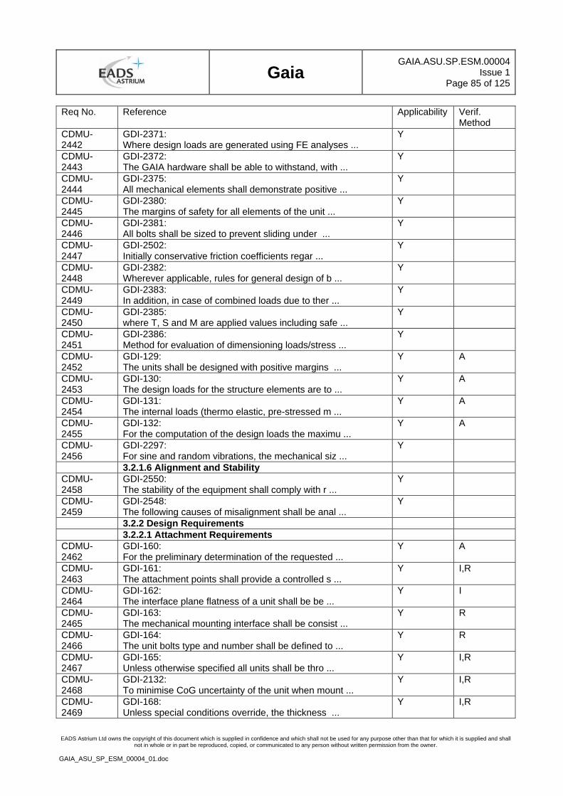
Gaia
GAIA.ASU.SP.ESM.00004Issue 1
Page 85 of 125
EADS Astrium Ltd owns the copyright of this document which is supplied in confidence and which shall not be used for any purpose other than that for which it is supplied and shall not in whole or in part be reproduced, copied, or communicated to any person without written permission from the owner.
GAIA_ASU_SP_ESM_00004_01.doc
Req No. Reference Applicability Verif. Method
CDMU-2442
GDI-2371: Where design loads are generated using FE analyses ...
Y
CDMU-2443
GDI-2372: The GAIA hardware shall be able to withstand, with ...
Y
CDMU-2444
GDI-2375: All mechanical elements shall demonstrate positive ...
Y
CDMU-2445
GDI-2380: The margins of safety for all elements of the unit ...
Y
CDMU-2446
GDI-2381: All bolts shall be sized to prevent sliding under ...
Y
CDMU-2447
GDI-2502: Initially conservative friction coefficients regar ...
Y
CDMU-2448
GDI-2382: Wherever applicable, rules for general design of b ...
Y
CDMU-2449
GDI-2383: In addition, in case of combined loads due to ther ...
Y
CDMU-2450
GDI-2385: where T, S and M are applied values including safe ...
Y
CDMU-2451
GDI-2386: Method for evaluation of dimensioning loads/stress ...
Y
CDMU-2452
GDI-129: The units shall be designed with positive margins ...
Y A
CDMU-2453
GDI-130: The design loads for the structure elements are to ...
Y A
CDMU-2454
GDI-131: The internal loads (thermo elastic, pre-stressed m ...
Y A
CDMU-2455
GDI-132: For the computation of the design loads the maximu ...
Y A
CDMU-2456
GDI-2297: For sine and random vibrations, the mechanical siz ...
Y
3.2.1.6 Alignment and Stability CDMU-2458
GDI-2550: The stability of the equipment shall comply with r ...
Y
CDMU-2459
GDI-2548: The following causes of misalignment shall be anal ...
Y
3.2.2 Design Requirements 3.2.2.1 Attachment Requirements CDMU-2462
GDI-160: For the preliminary determination of the requested ...
Y A
CDMU-2463
GDI-161: The attachment points shall provide a controlled s ...
Y I,R
CDMU-2464
GDI-162: The interface plane flatness of a unit shall be be ...
Y I
CDMU-2465
GDI-163: The mechanical mounting interface shall be consist ...
Y R
CDMU-2466
GDI-164: The unit bolts type and number shall be defined to ...
Y R
CDMU-2467
GDI-165: Unless otherwise specified all units shall be thro ...
Y I,R
CDMU-2468
GDI-2132: To minimise CoG uncertainty of the unit when mount ...
Y I,R
CDMU-2469
GDI-168: Unless special conditions override, the thickness ...
Y I,R
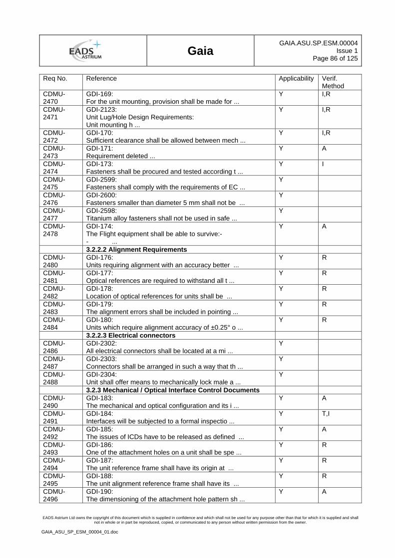
Gaia
GAIA.ASU.SP.ESM.00004Issue 1
Page 86 of 125
EADS Astrium Ltd owns the copyright of this document which is supplied in confidence and which shall not be used for any purpose other than that for which it is supplied and shall not in whole or in part be reproduced, copied, or communicated to any person without written permission from the owner.
GAIA_ASU_SP_ESM_00004_01.doc
Req No. Reference Applicability Verif. Method
CDMU-2470
GDI-169: For the unit mounting, provision shall be made for ...
Y I,R
CDMU-2471
GDI-2123: Unit Lug/Hole Design Requirements: Unit mounting h ...
Y I,R
CDMU-2472
GDI-170: Sufficient clearance shall be allowed between mech ...
Y I,R
CDMU-2473
GDI-171: Requirement deleted ...
Y A
CDMU-2474
GDI-173: Fasteners shall be procured and tested according t ...
Y I
CDMU-2475
GDI-2599: Fasteners shall comply with the requirements of EC ...
Y
CDMU-2476
GDI-2600: Fasteners smaller than diameter 5 mm shall not be ...
Y
CDMU-2477
GDI-2598: Titanium alloy fasteners shall not be used in safe ...
Y
CDMU-2478
GDI-174: The Flight equipment shall be able to survive:- - ...
Y A
3.2.2.2 Alignment Requirements CDMU-2480
GDI-176: Units requiring alignment with an accuracy better ...
Y R
CDMU-2481
GDI-177: Optical references are required to withstand all t ...
Y R
CDMU-2482
GDI-178: Location of optical references for units shall be ...
Y R
CDMU-2483
GDI-179: The alignment errors shall be included in pointing ...
Y R
CDMU-2484
GDI-180: Units which require alignment accuracy of ±0.25° o ...
Y R
3.2.2.3 Electrical connectors CDMU-2486
GDI-2302: All electrical connectors shall be located at a mi ...
Y
CDMU-2487
GDI-2303: Connectors shall be arranged in such a way that th ...
Y
CDMU-2488
GDI-2304: Unit shall offer means to mechanically lock male a ...
Y
3.2.3 Mechanical / Optical Interface Control Documents CDMU-2490
GDI-183: The mechanical and optical configuration and its i ...
Y A
CDMU-2491
GDI-184: Interfaces will be subjected to a formal inspectio ...
Y T,I
CDMU-2492
GDI-185: The issues of ICDs have to be released as defined ...
Y A
CDMU-2493
GDI-186: One of the attachment holes on a unit shall be spe ...
Y R
CDMU-2494
GDI-187: The unit reference frame shall have its origin at ...
Y R
CDMU-2495
GDI-188: The unit alignment reference frame shall have its ...
Y R
CDMU-2496
GDI-190: The dimensioning of the attachment hole pattern sh ...
Y A
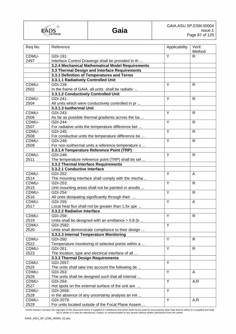
Gaia
GAIA.ASU.SP.ESM.00004Issue 1
Page 87 of 125
EADS Astrium Ltd owns the copyright of this document which is supplied in confidence and which shall not be used for any purpose other than that for which it is supplied and shall not in whole or in part be reproduced, copied, or communicated to any person without written permission from the owner.
GAIA_ASU_SP_ESM_00004_01.doc
Req No. Reference Applicability Verif. Method
CDMU-2497
GDI-191: Interface Control Drawings shall be provided to th ...
Y R
3.2.4 Mechanical Mathematical Model Requirements 3.3 Thermal Design and Interface Requirements 3.3.1 Definition of Temperatures and Terms 3.3.1.1 Radiatively Controlled Unit CDMU-2502
GDI-239: In the frame of GAIA, all units shall be radiativ ...
Y R
3.3.1.2 Conductively Controlled Unit CDMU-2504
GDI-241: All units which were conductively controlled in pr ...
Y R
3.3.1.3 Isothermal Unit CDMU-2506
GDI-243: As far as possible thermal gradients across the ba ...
Y R
CDMU-2507
GDI-244: For radiative units the temperature difference bet ...
Y R
CDMU-2508
GDI-245: For conductive units the temperature difference be ...
Y R
CDMU-2509
GDI-246: For non-isothermal units a reference temperature s ...
Y R
3.3.1.4 Temperature Reference Point (TRP) CDMU-2511
GDI-248: The temperature reference point (TRP) shall be sel ...
Y R
3.3.2 Thermal Interface Requirements 3.3.2.1 Conductive Interface CDMU-2514
GDI-252: The mounting interface shall comply with the mecha ...
Y A
CDMU-2515
GDI-253: Unit mounting areas shall not be painted or anodis ...
Y R
CDMU-2516
GDI-254: All units dissipating significantly through their ...
Y R
CDMU-2517
GDI-255: Local heat flux shall not be greater than 1.5x spe ...
Y A
3.3.2.2 Radiative Interface CDMU-2519
GDI-258: Units shall be designed with an emittance > 0.8 (b ...
Y R
CDMU-2520
GDI-2582: Units shall demonstrate compliance to their design ...
Y
3.3.2.3 Internal Temperature Monitoring CDMU-2522
GDI-260: Temperature monitoring of selected points within a ...
Y R
CDMU-2523
GDI-261: The location, type and electrical interface of all ...
Y R
3.3.3 Thermal Design Requirements CDMU-2525
GDI-2657: The units shall take into account the following de ...
Y
CDMU-2526
GDI-263: The units shall be designed such that all internal ...
Y A
CDMU-2527
GDI-264: Hot spots on the external surface of the unit are ...
Y A,R
CDMU-2528
GDI-2656: In the absence of any uncertainty analysis an init ...
Y
CDMU-2529
GDI-2079: For units located outside of the Focal Plane Assem ...
Y A,R
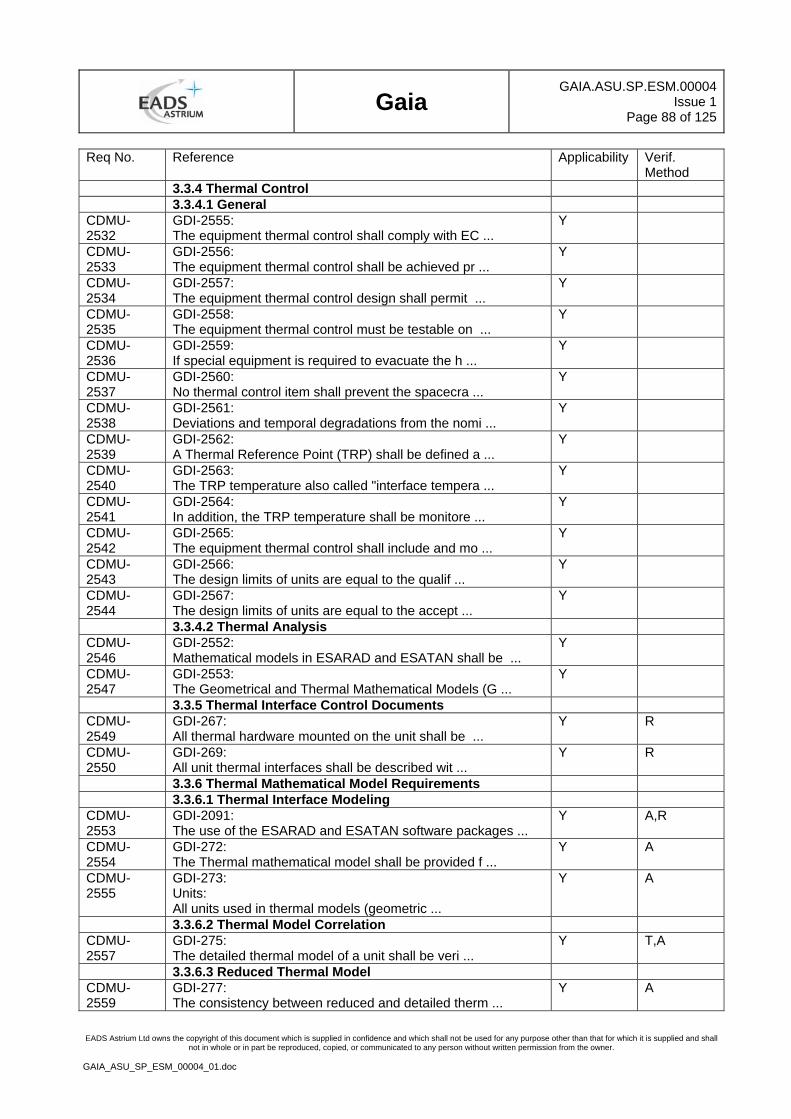
Gaia
GAIA.ASU.SP.ESM.00004Issue 1
Page 88 of 125
EADS Astrium Ltd owns the copyright of this document which is supplied in confidence and which shall not be used for any purpose other than that for which it is supplied and shall not in whole or in part be reproduced, copied, or communicated to any person without written permission from the owner.
GAIA_ASU_SP_ESM_00004_01.doc
Req No. Reference Applicability Verif. Method
3.3.4 Thermal Control 3.3.4.1 General CDMU-2532
GDI-2555: The equipment thermal control shall comply with EC ...
Y
CDMU-2533
GDI-2556: The equipment thermal control shall be achieved pr ...
Y
CDMU-2534
GDI-2557: The equipment thermal control design shall permit ...
Y
CDMU-2535
GDI-2558: The equipment thermal control must be testable on ...
Y
CDMU-2536
GDI-2559: If special equipment is required to evacuate the h ...
Y
CDMU-2537
GDI-2560: No thermal control item shall prevent the spacecra ...
Y
CDMU-2538
GDI-2561: Deviations and temporal degradations from the nomi ...
Y
CDMU-2539
GDI-2562: A Thermal Reference Point (TRP) shall be defined a ...
Y
CDMU-2540
GDI-2563: The TRP temperature also called "interface tempera ...
Y
CDMU-2541
GDI-2564: In addition, the TRP temperature shall be monitore ...
Y
CDMU-2542
GDI-2565: The equipment thermal control shall include and mo ...
Y
CDMU-2543
GDI-2566: The design limits of units are equal to the qualif ...
Y
CDMU-2544
GDI-2567: The design limits of units are equal to the accept ...
Y
3.3.4.2 Thermal Analysis CDMU-2546
GDI-2552: Mathematical models in ESARAD and ESATAN shall be ...
Y
CDMU-2547
GDI-2553: The Geometrical and Thermal Mathematical Models (G ...
Y
3.3.5 Thermal Interface Control Documents CDMU-2549
GDI-267: All thermal hardware mounted on the unit shall be ...
Y R
CDMU-2550
GDI-269: All unit thermal interfaces shall be described wit ...
Y R
3.3.6 Thermal Mathematical Model Requirements 3.3.6.1 Thermal Interface Modeling CDMU-2553
GDI-2091: The use of the ESARAD and ESATAN software packages ...
Y A,R
CDMU-2554
GDI-272: The Thermal mathematical model shall be provided f ...
Y A
CDMU-2555
GDI-273: Units: All units used in thermal models (geometric ...
Y A
3.3.6.2 Thermal Model Correlation CDMU-2557
GDI-275: The detailed thermal model of a unit shall be veri ...
Y T,A
3.3.6.3 Reduced Thermal Model CDMU-2559
GDI-277: The consistency between reduced and detailed therm ...
Y A
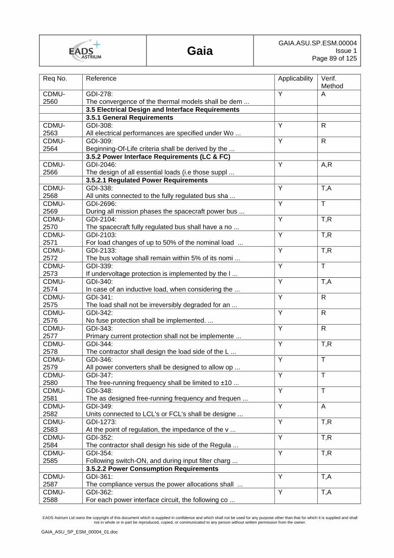
Gaia
GAIA.ASU.SP.ESM.00004Issue 1
Page 89 of 125
EADS Astrium Ltd owns the copyright of this document which is supplied in confidence and which shall not be used for any purpose other than that for which it is supplied and shall not in whole or in part be reproduced, copied, or communicated to any person without written permission from the owner.
GAIA_ASU_SP_ESM_00004_01.doc
Req No. Reference Applicability Verif. Method
CDMU-2560
GDI-278: The convergence of the thermal models shall be dem ...
Y A
3.5 Electrical Design and Interface Requirements 3.5.1 General Requirements CDMU-2563
GDI-308: All electrical performances are specified under Wo ...
Y R
CDMU-2564
GDI-309: Beginning-Of-Life criteria shall be derived by the ...
Y R
3.5.2 Power Interface Requirements (LC & FC) CDMU-2566
GDI-2046: The design of all essential loads (i.e those suppl ...
Y A,R
3.5.2.1 Regulated Power Requirements CDMU-2568
GDI-338: All units connected to the fully regulated bus sha ...
Y T,A
CDMU-2569
GDI-2696: During all mission phases the spacecraft power bus ...
Y T
CDMU-2570
GDI-2104: The spacecraft fully regulated bus shall have a no ...
Y T,R
CDMU-2571
GDI-2103: For load changes of up to 50% of the nominal load ...
Y T,R
CDMU-2572
GDI-2133: The bus voltage shall remain within 5% of its nomi ...
Y T,R
CDMU-2573
GDI-339: If undervoltage protection is implemented by the l ...
Y T
CDMU-2574
GDI-340: In case of an inductive load, when considering the ...
Y T,A
CDMU-2575
GDI-341: The load shall not be irreversibly degraded for an ...
Y R
CDMU-2576
GDI-342: No fuse protection shall be implemented. ...
Y R
CDMU-2577
GDI-343: Primary current protection shall not be implemente ...
Y R
CDMU-2578
GDI-344: The contractor shall design the load side of the L ...
Y T,R
CDMU-2579
GDI-346: All power converters shall be designed to allow op ...
Y T
CDMU-2580
GDI-347: The free-running frequency shall be limited to ±10 ...
Y T
CDMU-2581
GDI-348: The as designed free-running frequency and frequen ...
Y T
CDMU-2582
GDI-349: Units connected to LCL's or FCL's shall be designe ...
Y A
CDMU-2583
GDI-1273: At the point of regulation, the impedance of the v ...
Y T,R
CDMU-2584
GDI-352: The contractor shall design his side of the Regula ...
Y T,R
CDMU-2585
GDI-354: Following switch-ON, and during input filter charg ...
Y T,R
3.5.2.2 Power Consumption Requirements CDMU-2587
GDI-361: The compliance versus the power allocations shall ...
Y T,A
CDMU-2588
GDI-362: For each power interface circuit, the following co ...
Y T,A
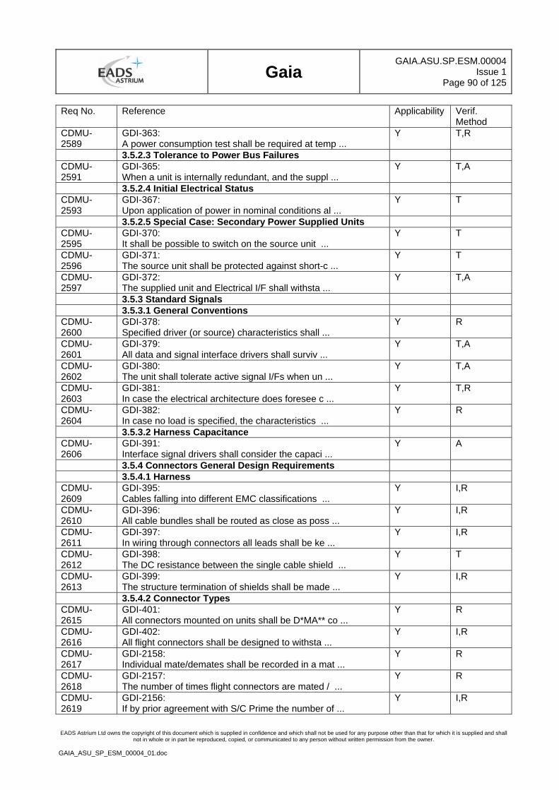
Gaia
GAIA.ASU.SP.ESM.00004Issue 1
Page 90 of 125
EADS Astrium Ltd owns the copyright of this document which is supplied in confidence and which shall not be used for any purpose other than that for which it is supplied and shall not in whole or in part be reproduced, copied, or communicated to any person without written permission from the owner.
GAIA_ASU_SP_ESM_00004_01.doc
Req No. Reference Applicability Verif. Method
CDMU-2589
GDI-363: A power consumption test shall be required at temp ...
Y T,R
3.5.2.3 Tolerance to Power Bus Failures CDMU-2591
GDI-365: When a unit is internally redundant, and the suppl ...
Y T,A
3.5.2.4 Initial Electrical Status CDMU-2593
GDI-367: Upon application of power in nominal conditions al ...
Y T
3.5.2.5 Special Case: Secondary Power Supplied Units CDMU-2595
GDI-370: It shall be possible to switch on the source unit ...
Y T
CDMU-2596
GDI-371: The source unit shall be protected against short-c ...
Y T
CDMU-2597
GDI-372: The supplied unit and Electrical I/F shall withsta ...
Y T,A
3.5.3 Standard Signals 3.5.3.1 General Conventions CDMU-2600
GDI-378: Specified driver (or source) characteristics shall ...
Y R
CDMU-2601
GDI-379: All data and signal interface drivers shall surviv ...
Y T,A
CDMU-2602
GDI-380: The unit shall tolerate active signal I/Fs when un ...
Y T,A
CDMU-2603
GDI-381: In case the electrical architecture does foresee c ...
Y T,R
CDMU-2604
GDI-382: In case no load is specified, the characteristics ...
Y R
3.5.3.2 Harness Capacitance CDMU-2606
GDI-391: Interface signal drivers shall consider the capaci ...
Y A
3.5.4 Connectors General Design Requirements 3.5.4.1 Harness CDMU-2609
GDI-395: Cables falling into different EMC classifications ...
Y I,R
CDMU-2610
GDI-396: All cable bundles shall be routed as close as poss ...
Y I,R
CDMU-2611
GDI-397: In wiring through connectors all leads shall be ke ...
Y I,R
CDMU-2612
GDI-398: The DC resistance between the single cable shield ...
Y T
CDMU-2613
GDI-399: The structure termination of shields shall be made ...
Y I,R
3.5.4.2 Connector Types CDMU-2615
GDI-401: All connectors mounted on units shall be D*MA** co ...
Y R
CDMU-2616
GDI-402: All flight connectors shall be designed to withsta ...
Y I,R
CDMU-2617
GDI-2158: Individual mate/demates shall be recorded in a mat ...
Y R
CDMU-2618
GDI-2157: The number of times flight connectors are mated / ...
Y R
CDMU-2619
GDI-2156: If by prior agreement with S/C Prime the number of ...
Y I,R
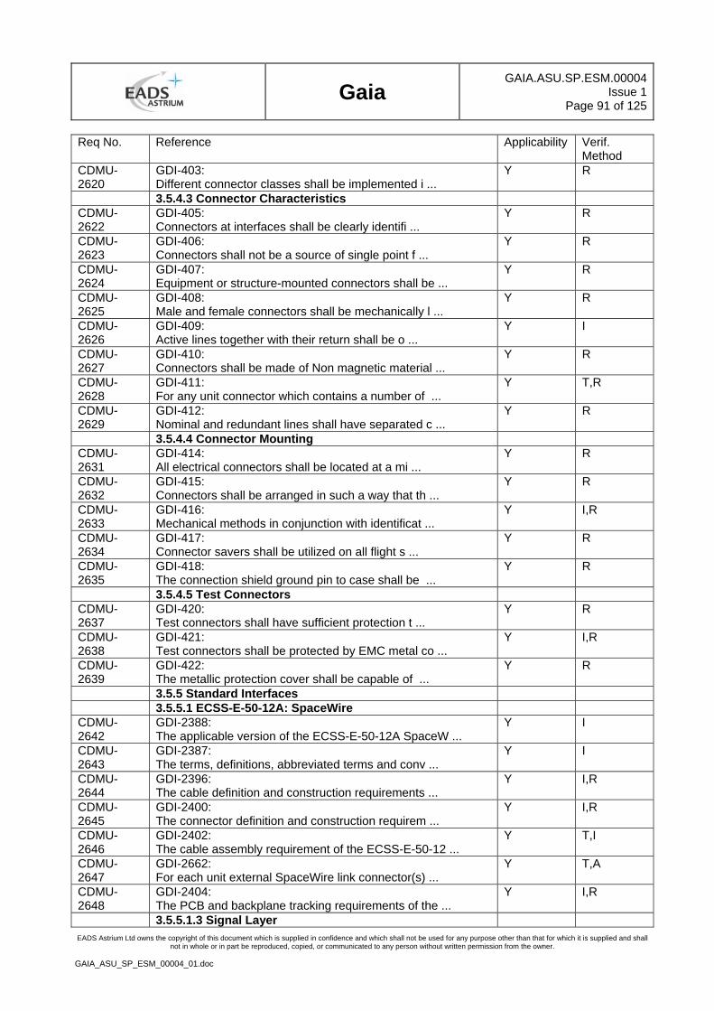
Gaia
GAIA.ASU.SP.ESM.00004Issue 1
Page 91 of 125
EADS Astrium Ltd owns the copyright of this document which is supplied in confidence and which shall not be used for any purpose other than that for which it is supplied and shall not in whole or in part be reproduced, copied, or communicated to any person without written permission from the owner.
GAIA_ASU_SP_ESM_00004_01.doc
Req No. Reference Applicability Verif. Method
CDMU-2620
GDI-403: Different connector classes shall be implemented i ...
Y R
3.5.4.3 Connector Characteristics CDMU-2622
GDI-405: Connectors at interfaces shall be clearly identifi ...
Y R
CDMU-2623
GDI-406: Connectors shall not be a source of single point f ...
Y R
CDMU-2624
GDI-407: Equipment or structure-mounted connectors shall be ...
Y R
CDMU-2625
GDI-408: Male and female connectors shall be mechanically l ...
Y R
CDMU-2626
GDI-409: Active lines together with their return shall be o ...
Y I
CDMU-2627
GDI-410: Connectors shall be made of Non magnetic material ...
Y R
CDMU-2628
GDI-411: For any unit connector which contains a number of ...
Y T,R
CDMU-2629
GDI-412: Nominal and redundant lines shall have separated c ...
Y R
3.5.4.4 Connector Mounting CDMU-2631
GDI-414: All electrical connectors shall be located at a mi ...
Y R
CDMU-2632
GDI-415: Connectors shall be arranged in such a way that th ...
Y R
CDMU-2633
GDI-416: Mechanical methods in conjunction with identificat ...
Y I,R
CDMU-2634
GDI-417: Connector savers shall be utilized on all flight s ...
Y R
CDMU-2635
GDI-418: The connection shield ground pin to case shall be ...
Y R
3.5.4.5 Test Connectors CDMU-2637
GDI-420: Test connectors shall have sufficient protection t ...
Y R
CDMU-2638
GDI-421: Test connectors shall be protected by EMC metal co ...
Y I,R
CDMU-2639
GDI-422: The metallic protection cover shall be capable of ...
Y R
3.5.5 Standard Interfaces 3.5.5.1 ECSS-E-50-12A: SpaceWire CDMU-2642
GDI-2388: The applicable version of the ECSS-E-50-12A SpaceW ...
Y I
CDMU-2643
GDI-2387: The terms, definitions, abbreviated terms and conv ...
Y I
CDMU-2644
GDI-2396: The cable definition and construction requirements ...
Y I,R
CDMU-2645
GDI-2400: The connector definition and construction requirem ...
Y I,R
CDMU-2646
GDI-2402: The cable assembly requirement of the ECSS-E-50-12 ...
Y T,I
CDMU-2647
GDI-2662: For each unit external SpaceWire link connector(s) ...
Y T,A
CDMU-2648
GDI-2404: The PCB and backplane tracking requirements of the ...
Y I,R
3.5.5.1.3 Signal Layer
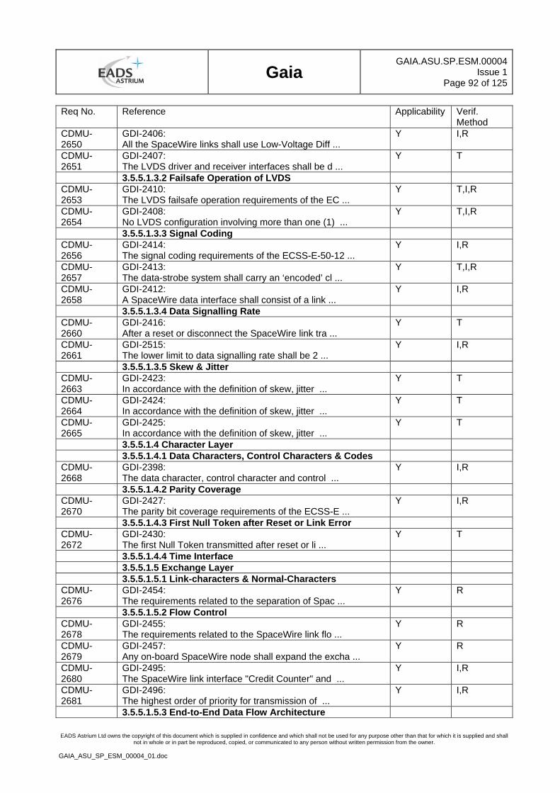
Gaia
GAIA.ASU.SP.ESM.00004Issue 1
Page 92 of 125
EADS Astrium Ltd owns the copyright of this document which is supplied in confidence and which shall not be used for any purpose other than that for which it is supplied and shall not in whole or in part be reproduced, copied, or communicated to any person without written permission from the owner.
GAIA_ASU_SP_ESM_00004_01.doc
Req No. Reference Applicability Verif. Method
CDMU-2650
GDI-2406: All the SpaceWire links shall use Low-Voltage Diff ...
Y I,R
CDMU-2651
GDI-2407: The LVDS driver and receiver interfaces shall be d ...
Y T
3.5.5.1.3.2 Failsafe Operation of LVDS CDMU-2653
GDI-2410: The LVDS failsafe operation requirements of the EC ...
Y T,I,R
CDMU-2654
GDI-2408: No LVDS configuration involving more than one (1) ...
Y T,I,R
3.5.5.1.3.3 Signal Coding CDMU-2656
GDI-2414: The signal coding requirements of the ECSS-E-50-12 ...
Y I,R
CDMU-2657
GDI-2413: The data-strobe system shall carry an ‘encoded’ cl ...
Y T,I,R
CDMU-2658
GDI-2412: A SpaceWire data interface shall consist of a link ...
Y I,R
3.5.5.1.3.4 Data Signalling Rate CDMU-2660
GDI-2416: After a reset or disconnect the SpaceWire link tra ...
Y T
CDMU-2661
GDI-2515: The lower limit to data signalling rate shall be 2 ...
Y I,R
3.5.5.1.3.5 Skew & Jitter CDMU-2663
GDI-2423: In accordance with the definition of skew, jitter ...
Y T
CDMU-2664
GDI-2424: In accordance with the definition of skew, jitter ...
Y T
CDMU-2665
GDI-2425: In accordance with the definition of skew, jitter ...
Y T
3.5.5.1.4 Character Layer 3.5.5.1.4.1 Data Characters, Control Characters & Codes CDMU-2668
GDI-2398: The data character, control character and control ...
Y I,R
3.5.5.1.4.2 Parity Coverage CDMU-2670
GDI-2427: The parity bit coverage requirements of the ECSS-E ...
Y I,R
3.5.5.1.4.3 First Null Token after Reset or Link Error CDMU-2672
GDI-2430: The first Null Token transmitted after reset or li ...
Y T
3.5.5.1.4.4 Time Interface 3.5.5.1.5 Exchange Layer 3.5.5.1.5.1 Link-characters & Normal-Characters CDMU-2676
GDI-2454: The requirements related to the separation of Spac ...
Y R
3.5.5.1.5.2 Flow Control CDMU-2678
GDI-2455: The requirements related to the SpaceWire link flo ...
Y R
CDMU-2679
GDI-2457: Any on-board SpaceWire node shall expand the excha ...
Y R
CDMU-2680
GDI-2495: The SpaceWire link interface "Credit Counter" and ...
Y I,R
CDMU-2681
GDI-2496: The highest order of priority for transmission of ...
Y I,R
3.5.5.1.5.3 End-to-End Data Flow Architecture
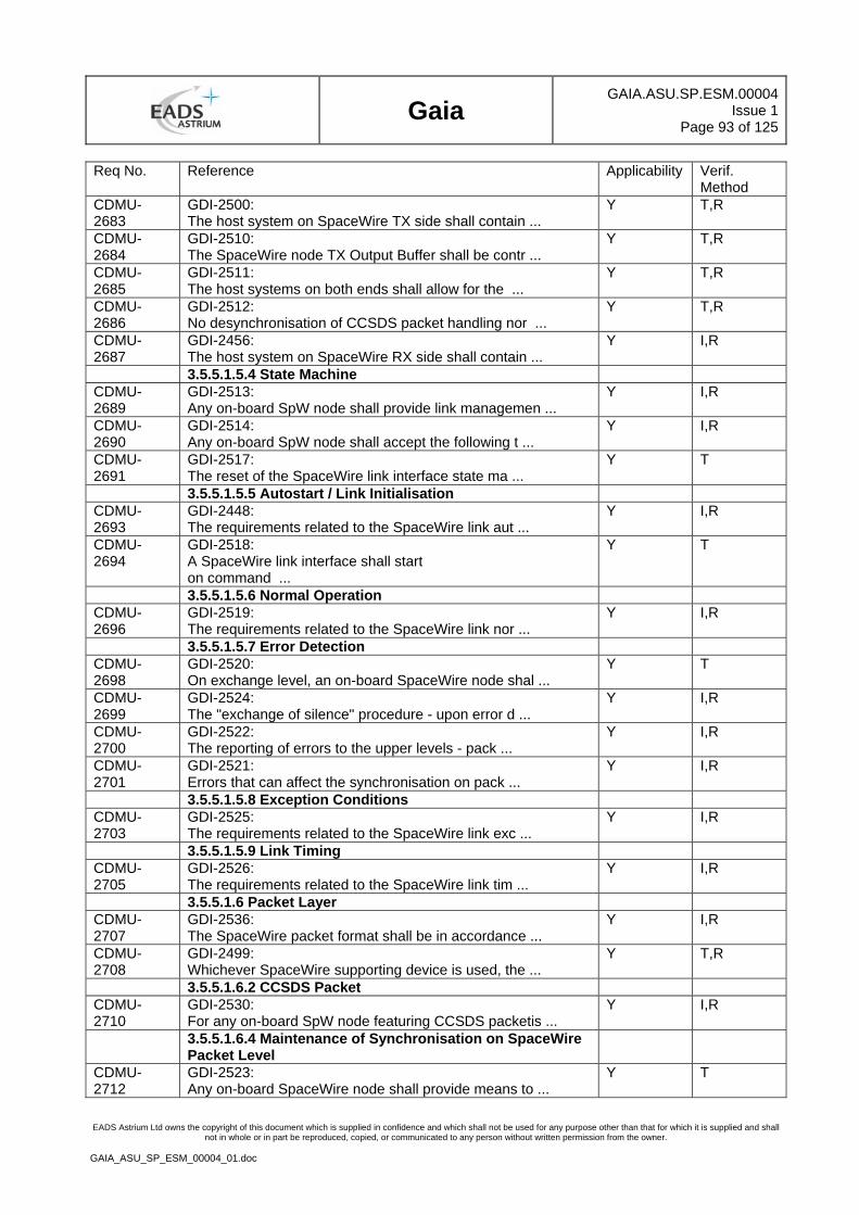
Gaia
GAIA.ASU.SP.ESM.00004Issue 1
Page 93 of 125
EADS Astrium Ltd owns the copyright of this document which is supplied in confidence and which shall not be used for any purpose other than that for which it is supplied and shall not in whole or in part be reproduced, copied, or communicated to any person without written permission from the owner.
GAIA_ASU_SP_ESM_00004_01.doc
Req No. Reference Applicability Verif. Method
CDMU-2683
GDI-2500: The host system on SpaceWire TX side shall contain ...
Y T,R
CDMU-2684
GDI-2510: The SpaceWire node TX Output Buffer shall be contr ...
Y T,R
CDMU-2685
GDI-2511: The host systems on both ends shall allow for the ...
Y T,R
CDMU-2686
GDI-2512: No desynchronisation of CCSDS packet handling nor ...
Y T,R
CDMU-2687
GDI-2456: The host system on SpaceWire RX side shall contain ...
Y I,R
3.5.5.1.5.4 State Machine CDMU-2689
GDI-2513: Any on-board SpW node shall provide link managemen ...
Y I,R
CDMU-2690
GDI-2514: Any on-board SpW node shall accept the following t ...
Y I,R
CDMU-2691
GDI-2517: The reset of the SpaceWire link interface state ma ...
Y T
3.5.5.1.5.5 Autostart / Link Initialisation CDMU-2693
GDI-2448: The requirements related to the SpaceWire link aut ...
Y I,R
CDMU-2694
GDI-2518: A SpaceWire link interface shall start on command ...
Y T
3.5.5.1.5.6 Normal Operation CDMU-2696
GDI-2519: The requirements related to the SpaceWire link nor ...
Y I,R
3.5.5.1.5.7 Error Detection CDMU-2698
GDI-2520: On exchange level, an on-board SpaceWire node shal ...
Y T
CDMU-2699
GDI-2524: The "exchange of silence" procedure - upon error d ...
Y I,R
CDMU-2700
GDI-2522: The reporting of errors to the upper levels - pack ...
Y I,R
CDMU-2701
GDI-2521: Errors that can affect the synchronisation on pack ...
Y I,R
3.5.5.1.5.8 Exception Conditions CDMU-2703
GDI-2525: The requirements related to the SpaceWire link exc ...
Y I,R
3.5.5.1.5.9 Link Timing CDMU-2705
GDI-2526: The requirements related to the SpaceWire link tim ...
Y I,R
3.5.5.1.6 Packet Layer CDMU-2707
GDI-2536: The SpaceWire packet format shall be in accordance ...
Y I,R
CDMU-2708
GDI-2499: Whichever SpaceWire supporting device is used, the ...
Y T,R
3.5.5.1.6.2 CCSDS Packet CDMU-2710
GDI-2530: For any on-board SpW node featuring CCSDS packetis ...
Y I,R
3.5.5.1.6.4 Maintenance of Synchronisation on SpaceWire Packet Level
CDMU-2712
GDI-2523: Any on-board SpaceWire node shall provide means to ...
Y T
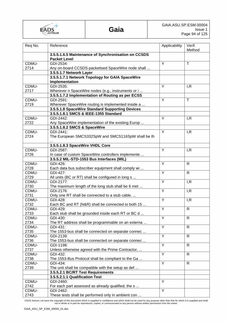
Gaia
GAIA.ASU.SP.ESM.00004Issue 1
Page 94 of 125
EADS Astrium Ltd owns the copyright of this document which is supplied in confidence and which shall not be used for any purpose other than that for which it is supplied and shall not in whole or in part be reproduced, copied, or communicated to any person without written permission from the owner.
GAIA_ASU_SP_ESM_00004_01.doc
Req No. Reference Applicability Verif. Method
3.5.5.1.6.5 Maintenance of Synchronisation on CCSDS Packet Level
CDMU-2714
GDI-2534: Any on-board CCSDS-packetised SpaceWire node shall ...
Y T
3.5.5.1.7 Network Layer 3.5.5.1.7.1 Network Topology for GAIA SpaceWire
Implementation
CDMU-2717
GDI-2535: Wherever n SpaceWire nodes (e.g., instruments or i ...
Y I,R
3.5.5.1.7.2 Implementation of Routing as per ECSS CDMU-2719
GDI-2591: Wherever SpaceWire routing is implemented inside a ...
Y T
3.5.5.1.8 SpaceWire Standard Supporting Devices 3.5.5.1.8.1 SMCS & IEEE-1355 Standard CDMU-2722
GDI-2442: Any SpaceWire implementation of the existing Europ ...
Y I,R
3.5.5.1.8.2 SMCS & SpaceWire CDMU-2724
GDI-2441: The European SMCS332SpW and SMCS116SpW shall be th ...
Y I,R
3.5.5.1.8.3 SpaceWire VHDL Core CDMU-2726
GDI-2587: In case of custom SpaceWire controllers implemente ...
Y I,R
3.5.5.2 MIL-STD-1553 Bus Interfaces (MIL) CDMU-2728
GDI-426: Each data bus subscriber equipment shall comply wi ...
Y R
CDMU-2729
GDI-427: All units (BC or RT) shall be configured in long s ...
Y R
CDMU-2730
GDI-2177: The maximum length of the long stub shall be 6 met ...
Y I,R
CDMU-2731
GDI-2176: Only one RT shall be connected to a stub cable. ...
Y I,R
CDMU-2732
GDI-428: Each BC and RT (N&R) shall be connected to both 15 ...
Y I,R
CDMU-2733
GDI-429: Each stub shall be grounded inside each RT or BC d ...
Y R
CDMU-2734
GDI-430: The RT address shall be programmable on an externa ...
Y R
CDMU-2735
GDI-431: The 1553-bus shall be connected on separate connec ...
Y R
CDMU-2736
GDI-2139: The 1553-bus shall be connected on separate connec ...
Y R
CDMU-2737
GDI-1198: Unless otherwise agreed with the Prime Contractor, ...
Y R
CDMU-2738
GDI-432: The 1553-Bus Protocol shall be compliant to the Ga ...
Y R
CDMU-2739
GDI-434: The unit shall be compatible with the setup as def ...
Y R
3.5.5.2.1 BC/RT Test Requirements 3.5.5.2.1.1 Qualification Test CDMU-2742
GDI-2460: For each part assessed as already qualified, the s ...
Y
CDMU-2743
GDI-2462: These tests shall be performed only in ambient con ...
Y
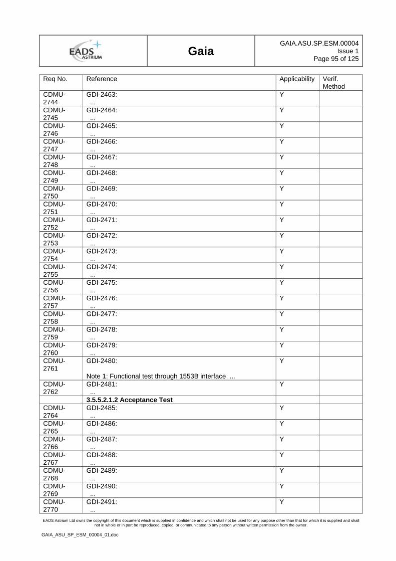
Gaia
GAIA.ASU.SP.ESM.00004Issue 1
Page 95 of 125
EADS Astrium Ltd owns the copyright of this document which is supplied in confidence and which shall not be used for any purpose other than that for which it is supplied and shall not in whole or in part be reproduced, copied, or communicated to any person without written permission from the owner.
GAIA_ASU_SP_ESM_00004_01.doc
Req No. Reference Applicability Verif. Method
CDMU-2744
GDI-2463: ...
Y
CDMU-2745
GDI-2464: ...
Y
CDMU-2746
GDI-2465: ...
Y
CDMU-2747
GDI-2466: ...
Y
CDMU-2748
GDI-2467: ...
Y
CDMU-2749
GDI-2468: ...
Y
CDMU-2750
GDI-2469: ...
Y
CDMU-2751
GDI-2470: ...
Y
CDMU-2752
GDI-2471: ...
Y
CDMU-2753
GDI-2472: ...
Y
CDMU-2754
GDI-2473: ...
Y
CDMU-2755
GDI-2474: ...
Y
CDMU-2756
GDI-2475: ...
Y
CDMU-2757
GDI-2476: ...
Y
CDMU-2758
GDI-2477: ...
Y
CDMU-2759
GDI-2478: ...
Y
CDMU-2760
GDI-2479: ...
Y
CDMU-2761
GDI-2480: Note 1: Functional test through 1553B interface ...
Y
CDMU-2762
GDI-2481: ...
Y
3.5.5.2.1.2 Acceptance Test CDMU-2764
GDI-2485: ...
Y
CDMU-2765
GDI-2486: ...
Y
CDMU-2766
GDI-2487: ...
Y
CDMU-2767
GDI-2488: ...
Y
CDMU-2768
GDI-2489: ...
Y
CDMU-2769
GDI-2490: ...
Y
CDMU-2770
GDI-2491: ...
Y
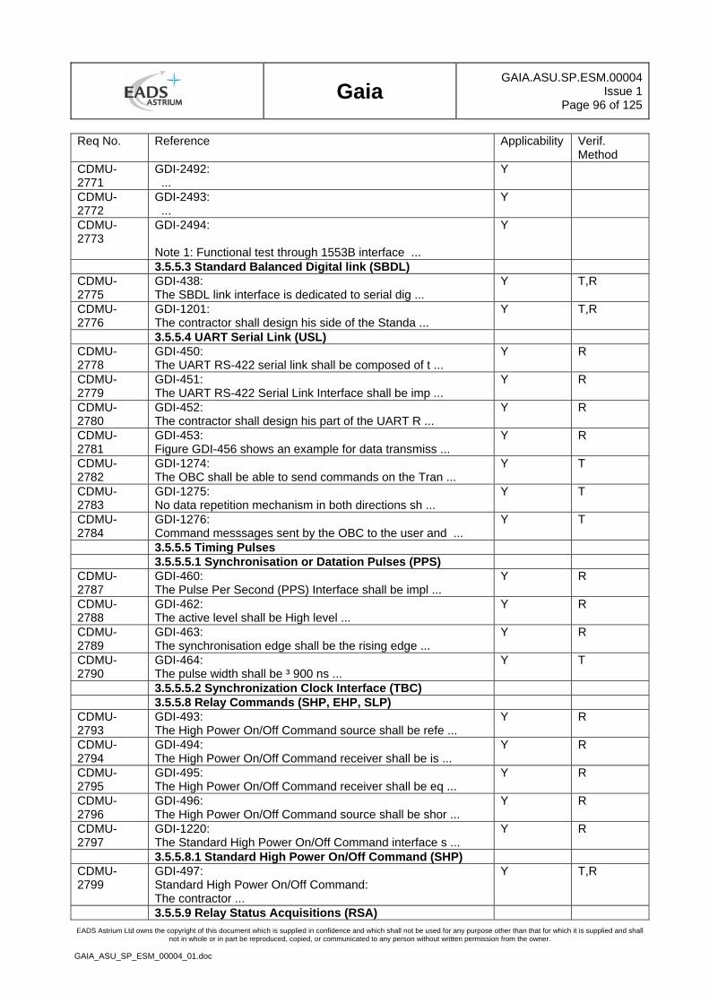
Gaia
GAIA.ASU.SP.ESM.00004Issue 1
Page 96 of 125
EADS Astrium Ltd owns the copyright of this document which is supplied in confidence and which shall not be used for any purpose other than that for which it is supplied and shall not in whole or in part be reproduced, copied, or communicated to any person without written permission from the owner.
GAIA_ASU_SP_ESM_00004_01.doc
Req No. Reference Applicability Verif. Method
CDMU-2771
GDI-2492: ...
Y
CDMU-2772
GDI-2493: ...
Y
CDMU-2773
GDI-2494: Note 1: Functional test through 1553B interface ...
Y
3.5.5.3 Standard Balanced Digital link (SBDL) CDMU-2775
GDI-438: The SBDL link interface is dedicated to serial dig ...
Y T,R
CDMU-2776
GDI-1201: The contractor shall design his side of the Standa ...
Y T,R
3.5.5.4 UART Serial Link (USL) CDMU-2778
GDI-450: The UART RS-422 serial link shall be composed of t ...
Y R
CDMU-2779
GDI-451: The UART RS-422 Serial Link Interface shall be imp ...
Y R
CDMU-2780
GDI-452: The contractor shall design his part of the UART R ...
Y R
CDMU-2781
GDI-453: Figure GDI-456 shows an example for data transmiss ...
Y R
CDMU-2782
GDI-1274: The OBC shall be able to send commands on the Tran ...
Y T
CDMU-2783
GDI-1275: No data repetition mechanism in both directions sh ...
Y T
CDMU-2784
GDI-1276: Command messsages sent by the OBC to the user and ...
Y T
3.5.5.5 Timing Pulses 3.5.5.5.1 Synchronisation or Datation Pulses (PPS) CDMU-2787
GDI-460: The Pulse Per Second (PPS) Interface shall be impl ...
Y R
CDMU-2788
GDI-462: The active level shall be High level ...
Y R
CDMU-2789
GDI-463: The synchronisation edge shall be the rising edge ...
Y R
CDMU-2790
GDI-464: The pulse width shall be ³ 900 ns ...
Y T
3.5.5.5.2 Synchronization Clock Interface (TBC) 3.5.5.8 Relay Commands (SHP, EHP, SLP) CDMU-2793
GDI-493: The High Power On/Off Command source shall be refe ...
Y R
CDMU-2794
GDI-494: The High Power On/Off Command receiver shall be is ...
Y R
CDMU-2795
GDI-495: The High Power On/Off Command receiver shall be eq ...
Y R
CDMU-2796
GDI-496: The High Power On/Off Command source shall be shor ...
Y R
CDMU-2797
GDI-1220: The Standard High Power On/Off Command interface s ...
Y R
3.5.5.8.1 Standard High Power On/Off Command (SHP) CDMU-2799
GDI-497: Standard High Power On/Off Command: The contractor ...
Y T,R
3.5.5.9 Relay Status Acquisitions (RSA)
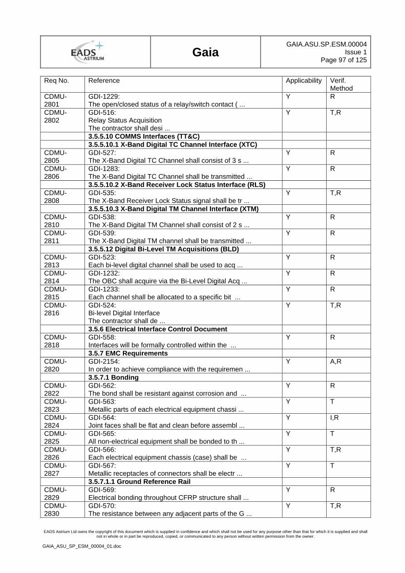
Gaia
GAIA.ASU.SP.ESM.00004Issue 1
Page 97 of 125
EADS Astrium Ltd owns the copyright of this document which is supplied in confidence and which shall not be used for any purpose other than that for which it is supplied and shall not in whole or in part be reproduced, copied, or communicated to any person without written permission from the owner.
GAIA_ASU_SP_ESM_00004_01.doc
Req No. Reference Applicability Verif. Method
CDMU-2801
GDI-1229: The open/closed status of a relay/switch contact ( ...
Y R
CDMU-2802
GDI-516: Relay Status Acquisition The contractor shall desi ...
Y T,R
3.5.5.10 COMMS Interfaces (TT&C) 3.5.5.10.1 X-Band Digital TC Channel Interface (XTC) CDMU-2805
GDI-527: The X-Band Digital TC Channel shall consist of 3 s ...
Y R
CDMU-2806
GDI-1283: The X-Band Digital TC Channel shall be transmitted ...
Y R
3.5.5.10.2 X-Band Receiver Lock Status Interface (RLS) CDMU-2808
GDI-535: The X-Band Receiver Lock Status signal shall be tr ...
Y T,R
3.5.5.10.3 X-Band Digital TM Channel Interface (XTM) CDMU-2810
GDI-538: The X-Band Digital TM Channel shall consist of 2 s ...
Y R
CDMU-2811
GDI-539: The X-Band Digital TM channel shall be transmitted ...
Y R
3.5.5.12 Digital Bi-Level TM Acquisitions (BLD) CDMU-2813
GDI-523: Each bi-level digital channel shall be used to acq ...
Y R
CDMU-2814
GDI-1232: The OBC shall acquire via the Bi-Level Digital Acq ...
Y R
CDMU-2815
GDI-1233: Each channel shall be allocated to a specific bit ...
Y R
CDMU-2816
GDI-524: Bi-level Digital Interface The contractor shall de ...
Y T,R
3.5.6 Electrical Interface Control Document CDMU-2818
GDI-558: Interfaces will be formally controlled within the ...
Y R
3.5.7 EMC Requirements CDMU-2820
GDI-2154: In order to achieve compliance with the requiremen ...
Y A,R
3.5.7.1 Bonding CDMU-2822
GDI-562: The bond shall be resistant against corrosion and ...
Y R
CDMU-2823
GDI-563: Metallic parts of each electrical equipment chassi ...
Y T
CDMU-2824
GDI-564: Joint faces shall be flat and clean before assembl ...
Y I,R
CDMU-2825
GDI-565: All non-electrical equipment shall be bonded to th ...
Y T
CDMU-2826
GDI-566: Each electrical equipment chassis (case) shall be ...
Y T,R
CDMU-2827
GDI-567: Metallic receptacles of connectors shall be electr ...
Y T
3.5.7.1.1 Ground Reference Rail CDMU-2829
GDI-569: Electrical bonding throughout CFRP structure shall ...
Y R
CDMU-2830
GDI-570: The resistance between any adjacent parts of the G ...
Y T,R
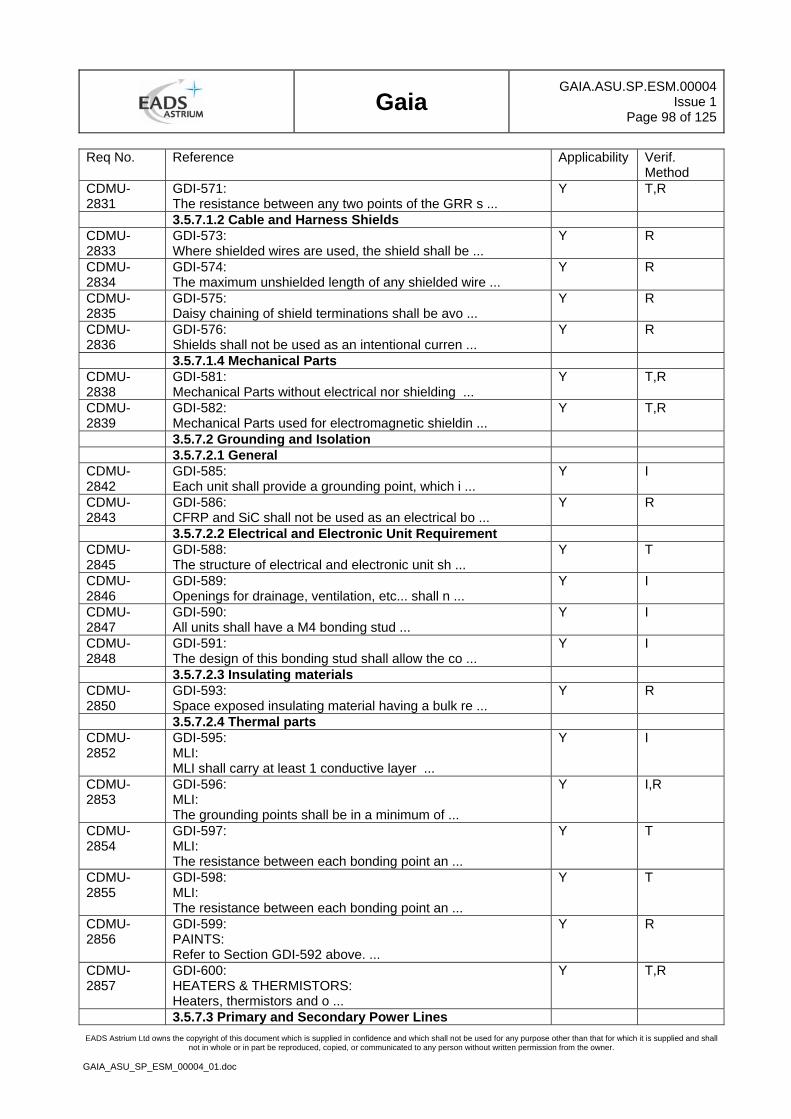
Gaia
GAIA.ASU.SP.ESM.00004Issue 1
Page 98 of 125
EADS Astrium Ltd owns the copyright of this document which is supplied in confidence and which shall not be used for any purpose other than that for which it is supplied and shall not in whole or in part be reproduced, copied, or communicated to any person without written permission from the owner.
GAIA_ASU_SP_ESM_00004_01.doc
Req No. Reference Applicability Verif. Method
CDMU-2831
GDI-571: The resistance between any two points of the GRR s ...
Y T,R
3.5.7.1.2 Cable and Harness Shields CDMU-2833
GDI-573: Where shielded wires are used, the shield shall be ...
Y R
CDMU-2834
GDI-574: The maximum unshielded length of any shielded wire ...
Y R
CDMU-2835
GDI-575: Daisy chaining of shield terminations shall be avo ...
Y R
CDMU-2836
GDI-576: Shields shall not be used as an intentional curren ...
Y R
3.5.7.1.4 Mechanical Parts CDMU-2838
GDI-581: Mechanical Parts without electrical nor shielding ...
Y T,R
CDMU-2839
GDI-582: Mechanical Parts used for electromagnetic shieldin ...
Y T,R
3.5.7.2 Grounding and Isolation 3.5.7.2.1 General CDMU-2842
GDI-585: Each unit shall provide a grounding point, which i ...
Y I
CDMU-2843
GDI-586: CFRP and SiC shall not be used as an electrical bo ...
Y R
3.5.7.2.2 Electrical and Electronic Unit Requirement CDMU-2845
GDI-588: The structure of electrical and electronic unit sh ...
Y T
CDMU-2846
GDI-589: Openings for drainage, ventilation, etc... shall n ...
Y I
CDMU-2847
GDI-590: All units shall have a M4 bonding stud ...
Y I
CDMU-2848
GDI-591: The design of this bonding stud shall allow the co ...
Y I
3.5.7.2.3 Insulating materials CDMU-2850
GDI-593: Space exposed insulating material having a bulk re ...
Y R
3.5.7.2.4 Thermal parts CDMU-2852
GDI-595: MLI: MLI shall carry at least 1 conductive layer ...
Y I
CDMU-2853
GDI-596: MLI: The grounding points shall be in a minimum of ...
Y I,R
CDMU-2854
GDI-597: MLI: The resistance between each bonding point an ...
Y T
CDMU-2855
GDI-598: MLI: The resistance between each bonding point an ...
Y T
CDMU-2856
GDI-599: PAINTS: Refer to Section GDI-592 above. ...
Y R
CDMU-2857
GDI-600: HEATERS & THERMISTORS: Heaters, thermistors and o ...
Y T,R
3.5.7.3 Primary and Secondary Power Lines
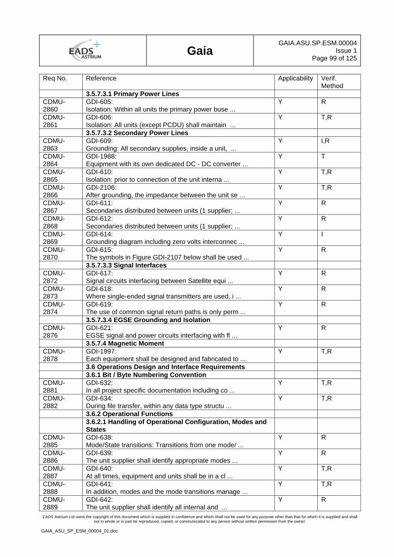
Gaia
GAIA.ASU.SP.ESM.00004Issue 1
Page 99 of 125
EADS Astrium Ltd owns the copyright of this document which is supplied in confidence and which shall not be used for any purpose other than that for which it is supplied and shall not in whole or in part be reproduced, copied, or communicated to any person without written permission from the owner.
GAIA_ASU_SP_ESM_00004_01.doc
Req No. Reference Applicability Verif. Method
3.5.7.3.1 Primary Power Lines CDMU-2860
GDI-605: Isolation: Within all units the primary power buse ...
Y R
CDMU-2861
GDI-606: Isolation: All units (except PCDU) shall maintain ...
Y T,R
3.5.7.3.2 Secondary Power Lines CDMU-2863
GDI-609: Grounding: All secondary supplies, inside a unit, ...
Y I,R
CDMU-2864
GDI-1988: Equipment with its own dedicated DC - DC converter ...
Y T
CDMU-2865
GDI-610: Isolation: prior to connection of the unit interna ...
Y T,R
CDMU-2866
GDI-2106: After grounding, the impedance between the unit se ...
Y T,R
CDMU-2867
GDI-611: Secondaries distributed between units (1 supplier; ...
Y R
CDMU-2868
GDI-612: Secondaries distributed between units (1 supplier; ...
Y R
CDMU-2869
GDI-614: Grounding diagram including zero volts interconnec ...
Y I
CDMU-2870
GDI-615: The symbols in Figure GDI-2107 below shall be used ...
Y R
3.5.7.3.3 Signal Interfaces CDMU-2872
GDI-617: Signal circuits interfacing between Satellite equi ...
Y R
CDMU-2873
GDI-618: Where single-ended signal transmitters are used, i ...
Y R
CDMU-2874
GDI-619: The use of common signal return paths is only perm ...
Y R
3.5.7.3.4 EGSE Grounding and Isolation CDMU-2876
GDI-621: EGSE signal and power circuits interfacing with fl ...
Y R
3.5.7.4 Magnetic Moment CDMU-2878
GDI-1997: Each equipment shall be designed and fabricated to ...
Y T,R
3.6 Operations Design and Interface Requirements 3.6.1 Bit / Byte Numbering Convention CDMU-2881
GDI-632: In all project specific documentation including co ...
Y T,R
CDMU-2882
GDI-634: During file transfer, within any data type structu ...
Y T,R
3.6.2 Operational Functions 3.6.2.1 Handling of Operational Configuration, Modes and
States
CDMU-2885
GDI-638: Mode/State transitions: Transitions from one mode/ ...
Y R
CDMU-2886
GDI-639: The unit supplier shall identify appropriate modes ...
Y R
CDMU-2887
GDI-640: At all times, equipment and units shall be in a cl ...
Y T,R
CDMU-2888
GDI-641: In addition, modes and the mode transitions manage ...
Y T,R
CDMU-2889
GDI-642: The unit supplier shall identify all internal and ...
Y R
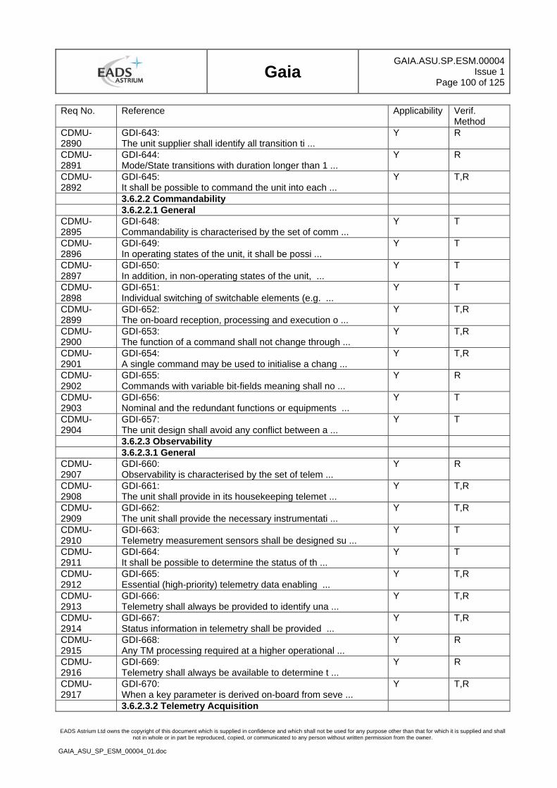
Gaia
GAIA.ASU.SP.ESM.00004Issue 1
Page 100 of 125
EADS Astrium Ltd owns the copyright of this document which is supplied in confidence and which shall not be used for any purpose other than that for which it is supplied and shall not in whole or in part be reproduced, copied, or communicated to any person without written permission from the owner.
GAIA_ASU_SP_ESM_00004_01.doc
Req No. Reference Applicability Verif. Method
CDMU-2890
GDI-643: The unit supplier shall identify all transition ti ...
Y R
CDMU-2891
GDI-644: Mode/State transitions with duration longer than 1 ...
Y R
CDMU-2892
GDI-645: It shall be possible to command the unit into each ...
Y T,R
3.6.2.2 Commandability 3.6.2.2.1 General CDMU-2895
GDI-648: Commandability is characterised by the set of comm ...
Y T
CDMU-2896
GDI-649: In operating states of the unit, it shall be possi ...
Y T
CDMU-2897
GDI-650: In addition, in non-operating states of the unit, ...
Y T
CDMU-2898
GDI-651: Individual switching of switchable elements (e.g. ...
Y T
CDMU-2899
GDI-652: The on-board reception, processing and execution o ...
Y T,R
CDMU-2900
GDI-653: The function of a command shall not change through ...
Y T,R
CDMU-2901
GDI-654: A single command may be used to initialise a chang ...
Y T,R
CDMU-2902
GDI-655: Commands with variable bit-fields meaning shall no ...
Y R
CDMU-2903
GDI-656: Nominal and the redundant functions or equipments ...
Y T
CDMU-2904
GDI-657: The unit design shall avoid any conflict between a ...
Y T
3.6.2.3 Observability 3.6.2.3.1 General CDMU-2907
GDI-660: Observability is characterised by the set of telem ...
Y R
CDMU-2908
GDI-661: The unit shall provide in its housekeeping telemet ...
Y T,R
CDMU-2909
GDI-662: The unit shall provide the necessary instrumentati ...
Y T,R
CDMU-2910
GDI-663: Telemetry measurement sensors shall be designed su ...
Y T
CDMU-2911
GDI-664: It shall be possible to determine the status of th ...
Y T
CDMU-2912
GDI-665: Essential (high-priority) telemetry data enabling ...
Y T,R
CDMU-2913
GDI-666: Telemetry shall always be provided to identify una ...
Y T,R
CDMU-2914
GDI-667: Status information in telemetry shall be provided ...
Y T,R
CDMU-2915
GDI-668: Any TM processing required at a higher operational ...
Y R
CDMU-2916
GDI-669: Telemetry shall always be available to determine t ...
Y R
CDMU-2917
GDI-670: When a key parameter is derived on-board from seve ...
Y T,R
3.6.2.3.2 Telemetry Acquisition
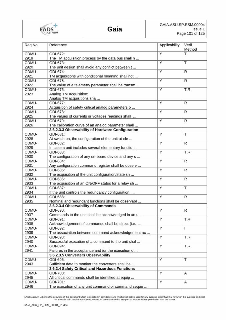
Gaia
GAIA.ASU.SP.ESM.00004Issue 1
Page 101 of 125
EADS Astrium Ltd owns the copyright of this document which is supplied in confidence and which shall not be used for any purpose other than that for which it is supplied and shall not in whole or in part be reproduced, copied, or communicated to any person without written permission from the owner.
GAIA_ASU_SP_ESM_00004_01.doc
Req No. Reference Applicability Verif. Method
CDMU-2919
GDI-672: The TM acquisition process by the data bus shall n ...
Y T
CDMU-2920
GDI-673: The unit design shall avoid any conflict between t ...
Y T
CDMU-2921
GDI-674: TM acquisitions with conditional meaning shall not ...
Y R
CDMU-2922
GDI-675: The value of a telemetry parameter shall be transm ...
Y R
CDMU-2923
GDI-676: Analog TM Acquisition: Analog TM acquisitions sha ...
Y T,R
CDMU-2924
GDI-677: Acquisition of safety critical analog parameters o ...
Y R
CDMU-2925
GDI-678: The values of currents or voltages readings shall ...
Y R
CDMU-2926
GDI-679: The calibration curve of an analog parameter shall ...
Y R
3.6.2.3.3 Observability of Hardware Configuration CDMU-2928
GDI-681: At switch on, the configuration of the unit at ele ...
Y T
CDMU-2929
GDI-682: In case a unit includes several elementary functio ...
Y R
CDMU-2930
GDI-683: The configuration of any on-board device and any s ...
Y T,R
CDMU-2931
GDI-684: Any configuration command register shall be observ ...
Y R
CDMU-2932
GDI-685: The acquisition of the unit configuration/state sh ...
Y R
CDMU-2933
GDI-686: The acquisition of an ON/OFF status for a relay sh ...
Y R
CDMU-2934
GDI-687: If the unit controls the redundancy configuration ...
Y T
CDMU-2935
GDI-688: Nominal and redundant functions shall be observabl ...
Y R
3.6.2.3.4 Observability of Commands CDMU-2937
GDI-690: Commands to the unit shall be acknowledged in an u ...
Y R
CDMU-2938
GDI-691: Acknowledgement of commands shall be direct (i.e. ...
Y T,R
CDMU-2939
GDI-692: The association between command acknowledgement ac ...
Y I
CDMU-2940
GDI-693: Successful execution of a command to the unit shal ...
Y T,R
CDMU-2941
GDI-694: Failures in the acceptance and /or the execution o ...
Y T,R
3.6.2.3.5 Converters Observability CDMU-2943
GDI-696: Sufficient data to monitor the converters shall be ...
Y T
3.6.2.4 Safety Critical and Hazardous Functions CDMU-2945
GDI-700: All critical commands shall be identified at equip ...
Y A
CDMU-2946
GDI-701: The execution of any unit command or command seque ...
Y A
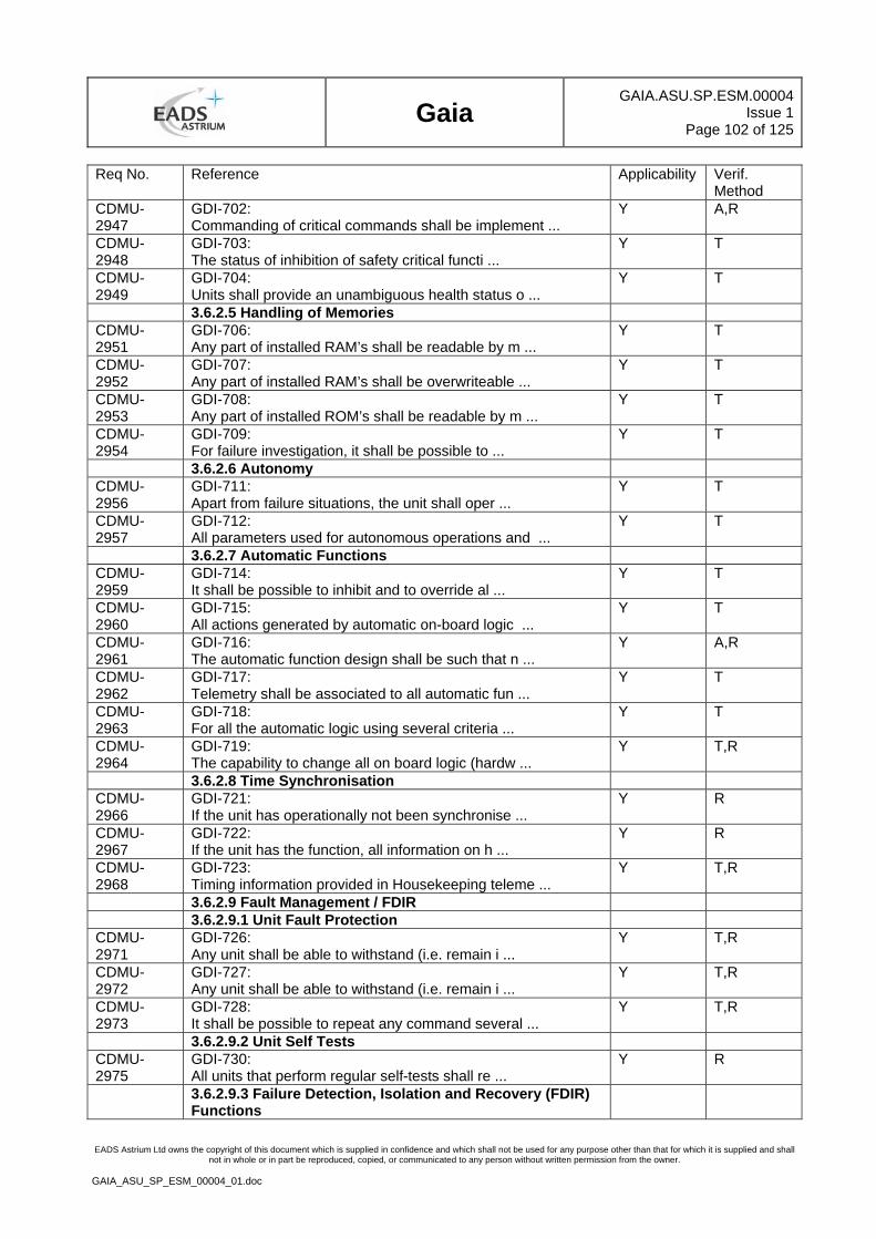
Gaia
GAIA.ASU.SP.ESM.00004Issue 1
Page 102 of 125
EADS Astrium Ltd owns the copyright of this document which is supplied in confidence and which shall not be used for any purpose other than that for which it is supplied and shall not in whole or in part be reproduced, copied, or communicated to any person without written permission from the owner.
GAIA_ASU_SP_ESM_00004_01.doc
Req No. Reference Applicability Verif. Method
CDMU-2947
GDI-702: Commanding of critical commands shall be implement ...
Y A,R
CDMU-2948
GDI-703: The status of inhibition of safety critical functi ...
Y T
CDMU-2949
GDI-704: Units shall provide an unambiguous health status o ...
Y T
3.6.2.5 Handling of Memories CDMU-2951
GDI-706: Any part of installed RAM’s shall be readable by m ...
Y T
CDMU-2952
GDI-707: Any part of installed RAM’s shall be overwriteable ...
Y T
CDMU-2953
GDI-708: Any part of installed ROM’s shall be readable by m ...
Y T
CDMU-2954
GDI-709: For failure investigation, it shall be possible to ...
Y T
3.6.2.6 Autonomy CDMU-2956
GDI-711: Apart from failure situations, the unit shall oper ...
Y T
CDMU-2957
GDI-712: All parameters used for autonomous operations and ...
Y T
3.6.2.7 Automatic Functions CDMU-2959
GDI-714: It shall be possible to inhibit and to override al ...
Y T
CDMU-2960
GDI-715: All actions generated by automatic on-board logic ...
Y T
CDMU-2961
GDI-716: The automatic function design shall be such that n ...
Y A,R
CDMU-2962
GDI-717: Telemetry shall be associated to all automatic fun ...
Y T
CDMU-2963
GDI-718: For all the automatic logic using several criteria ...
Y T
CDMU-2964
GDI-719: The capability to change all on board logic (hardw ...
Y T,R
3.6.2.8 Time Synchronisation CDMU-2966
GDI-721: If the unit has operationally not been synchronise ...
Y R
CDMU-2967
GDI-722: If the unit has the function, all information on h ...
Y R
CDMU-2968
GDI-723: Timing information provided in Housekeeping teleme ...
Y T,R
3.6.2.9 Fault Management / FDIR 3.6.2.9.1 Unit Fault Protection CDMU-2971
GDI-726: Any unit shall be able to withstand (i.e. remain i ...
Y T,R
CDMU-2972
GDI-727: Any unit shall be able to withstand (i.e. remain i ...
Y T,R
CDMU-2973
GDI-728: It shall be possible to repeat any command several ...
Y T,R
3.6.2.9.2 Unit Self Tests CDMU-2975
GDI-730: All units that perform regular self-tests shall re ...
Y R
3.6.2.9.3 Failure Detection, Isolation and Recovery (FDIR) Functions
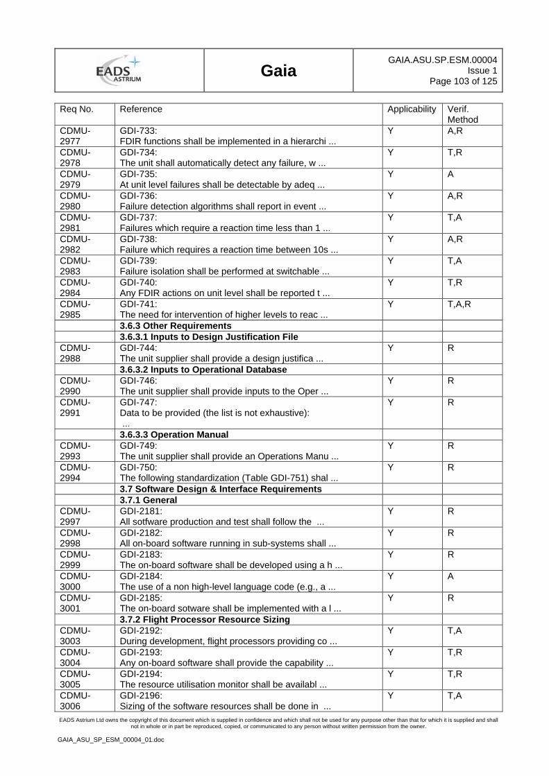
Gaia
GAIA.ASU.SP.ESM.00004Issue 1
Page 103 of 125
EADS Astrium Ltd owns the copyright of this document which is supplied in confidence and which shall not be used for any purpose other than that for which it is supplied and shall not in whole or in part be reproduced, copied, or communicated to any person without written permission from the owner.
GAIA_ASU_SP_ESM_00004_01.doc
Req No. Reference Applicability Verif. Method
CDMU-2977
GDI-733: FDIR functions shall be implemented in a hierarchi ...
Y A,R
CDMU-2978
GDI-734: The unit shall automatically detect any failure, w ...
Y T,R
CDMU-2979
GDI-735: At unit level failures shall be detectable by adeq ...
Y A
CDMU-2980
GDI-736: Failure detection algorithms shall report in event ...
Y A,R
CDMU-2981
GDI-737: Failures which require a reaction time less than 1 ...
Y T,A
CDMU-2982
GDI-738: Failure which requires a reaction time between 10s ...
Y A,R
CDMU-2983
GDI-739: Failure isolation shall be performed at switchable ...
Y T,A
CDMU-2984
GDI-740: Any FDIR actions on unit level shall be reported t ...
Y T,R
CDMU-2985
GDI-741: The need for intervention of higher levels to reac ...
Y T,A,R
3.6.3 Other Requirements 3.6.3.1 Inputs to Design Justification File CDMU-2988
GDI-744: The unit supplier shall provide a design justifica ...
Y R
3.6.3.2 Inputs to Operational Database CDMU-2990
GDI-746: The unit supplier shall provide inputs to the Oper ...
Y R
CDMU-2991
GDI-747: Data to be provided (the list is not exhaustive): ...
Y R
3.6.3.3 Operation Manual CDMU-2993
GDI-749: The unit supplier shall provide an Operations Manu ...
Y R
CDMU-2994
GDI-750: The following standardization (Table GDI-751) shal ...
Y R
3.7 Software Design & Interface Requirements 3.7.1 General CDMU-2997
GDI-2181: All sotfware production and test shall follow the ...
Y R
CDMU-2998
GDI-2182: All on-board software running in sub-systems shall ...
Y R
CDMU-2999
GDI-2183: The on-board software shall be developed using a h ...
Y R
CDMU-3000
GDI-2184: The use of a non high-level language code (e.g., a ...
Y A
CDMU-3001
GDI-2185: The on-board sotware shall be implemented with a l ...
Y R
3.7.2 Flight Processor Resource Sizing CDMU-3003
GDI-2192: During development, flight processors providing co ...
Y T,A
CDMU-3004
GDI-2193: Any on-board software shall provide the capability ...
Y T,R
CDMU-3005
GDI-2194: The resource utilisation monitor shall be availabl ...
Y T,R
CDMU-3006
GDI-2196: Sizing of the software resources shall be done in ...
Y T,A
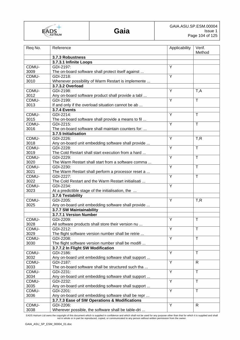
Gaia
GAIA.ASU.SP.ESM.00004Issue 1
Page 104 of 125
EADS Astrium Ltd owns the copyright of this document which is supplied in confidence and which shall not be used for any purpose other than that for which it is supplied and shall not in whole or in part be reproduced, copied, or communicated to any person without written permission from the owner.
GAIA_ASU_SP_ESM_00004_01.doc
Req No. Reference Applicability Verif. Method
3.7.3 Robustness 3.7.3.1 Infinite Loops CDMU-3009
GDI-2197: The on-board software shall protect itself against ...
Y
CDMU-3010
GDI-2218: Whenever possibility of Warm Restart is implemente ...
Y
3.7.3.2 Overload CDMU-3012
GDI-2198: Any on-board software product shall provide a tabl ...
Y T,A
CDMU-3013
GDI-2199: If and only if the overload situation cannot be ab ...
Y T
3.7.4 Events CDMU-3015
GDI-2214: The on-board software shall provide a means to fil ...
Y T
CDMU-3016
GDI-2215: The on-board software shall maintain counters for: ...
Y T
3.7.5 Initialisation CDMU-3018
GDI-2226: Any on-board unit embedding software shall provide ...
Y T,R
CDMU-3019
GDI-2228: The Cold Restart shall start execution from a hard ...
Y T
CDMU-3020
GDI-2229: The Warm Restart shall start from a software comma ...
Y T
CDMU-3021
GDI-2230: The Warm Restart shall perform a processor reset a ...
Y T
CDMU-3022
GDI-2227: The Cold Restart and the Warm Restart initialisati ...
Y T
CDMU-3023
GDI-2234: At a predictible stage of the initialisation, the ...
Y
3.7.6 Testability CDMU-3025
GDI-2205: Any on-board unit embedding software shall provide ...
Y T,R
3.7.7 SW Maintainability 3.7.7.1 Version Number CDMU-3028
GDI-2209: All software products shall store their version nu ...
Y T
CDMU-3029
GDI-2212: The flight software version number shall be retrie ...
Y T
CDMU-3030
GDI-2208: The flight software version number shall be modifi ...
Y T
3.7.7.2 In Flight SW Modification CDMU-3032
GDI-2186: Any on-board unit embedding software shall support ...
Y T
CDMU-3033
GDI-2187: The on-board software shall be structured such tha ...
Y R
CDMU-3034
GDI-2231: Any on-board unit embedding software shall support ...
Y T
CDMU-3035
GDI-2232: Any on-board unit embedding software shall support ...
Y T
CDMU-3036
GDI-2201: Any on-board unit embedding software shall be repr ...
Y T
3.7.7.3 Ease of SW Operations & Modifications CDMU-3038
GDI-2206: Wherever possible, the software shall be table-dri ...
Y R
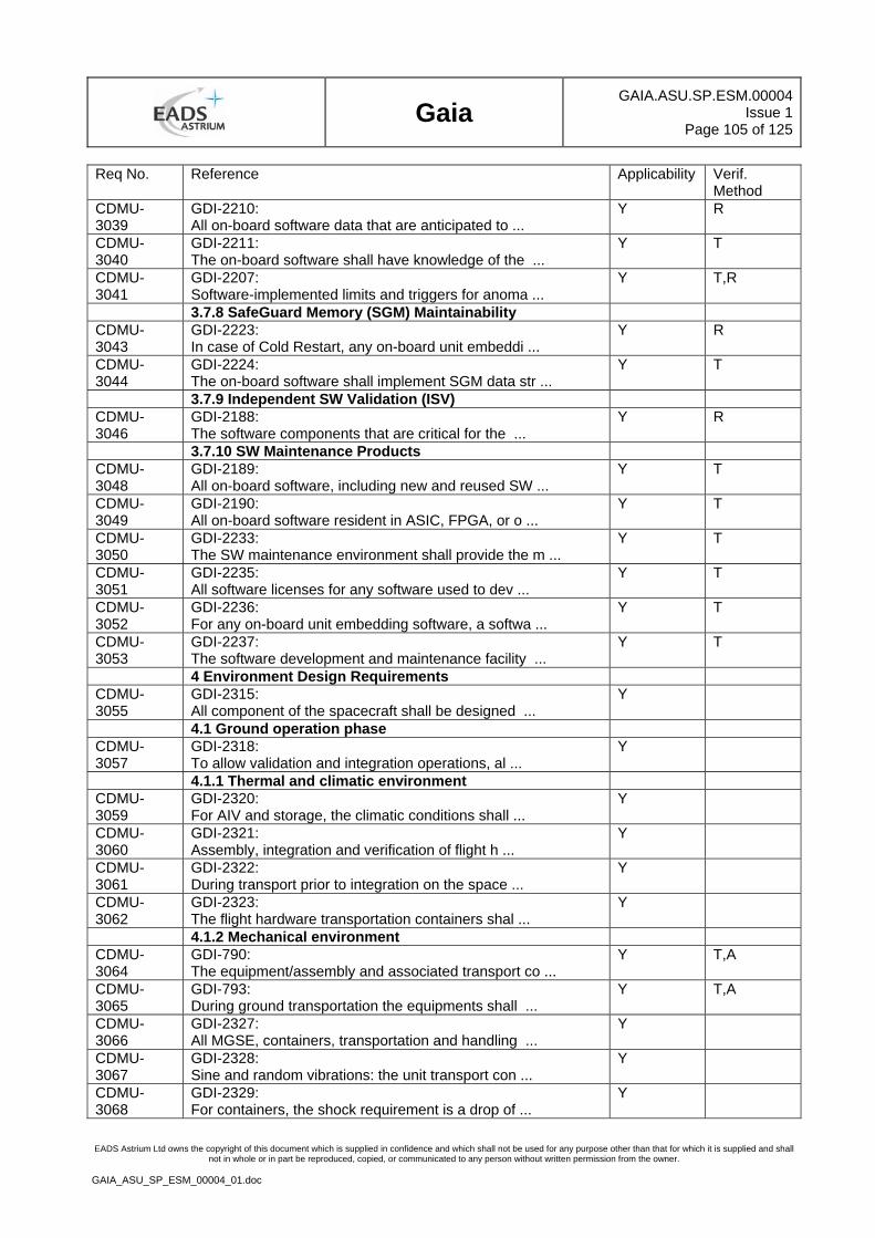
Gaia
GAIA.ASU.SP.ESM.00004Issue 1
Page 105 of 125
EADS Astrium Ltd owns the copyright of this document which is supplied in confidence and which shall not be used for any purpose other than that for which it is supplied and shall not in whole or in part be reproduced, copied, or communicated to any person without written permission from the owner.
GAIA_ASU_SP_ESM_00004_01.doc
Req No. Reference Applicability Verif. Method
CDMU-3039
GDI-2210: All on-board software data that are anticipated to ...
Y R
CDMU-3040
GDI-2211: The on-board software shall have knowledge of the ...
Y T
CDMU-3041
GDI-2207: Software-implemented limits and triggers for anoma ...
Y T,R
3.7.8 SafeGuard Memory (SGM) Maintainability CDMU-3043
GDI-2223: In case of Cold Restart, any on-board unit embeddi ...
Y R
CDMU-3044
GDI-2224: The on-board software shall implement SGM data str ...
Y T
3.7.9 Independent SW Validation (ISV) CDMU-3046
GDI-2188: The software components that are critical for the ...
Y R
3.7.10 SW Maintenance Products CDMU-3048
GDI-2189: All on-board software, including new and reused SW ...
Y T
CDMU-3049
GDI-2190: All on-board software resident in ASIC, FPGA, or o ...
Y T
CDMU-3050
GDI-2233: The SW maintenance environment shall provide the m ...
Y T
CDMU-3051
GDI-2235: All software licenses for any software used to dev ...
Y T
CDMU-3052
GDI-2236: For any on-board unit embedding software, a softwa ...
Y T
CDMU-3053
GDI-2237: The software development and maintenance facility ...
Y T
4 Environment Design Requirements CDMU-3055
GDI-2315: All component of the spacecraft shall be designed ...
Y
4.1 Ground operation phase CDMU-3057
GDI-2318: To allow validation and integration operations, al ...
Y
4.1.1 Thermal and climatic environment CDMU-3059
GDI-2320: For AIV and storage, the climatic conditions shall ...
Y
CDMU-3060
GDI-2321: Assembly, integration and verification of flight h ...
Y
CDMU-3061
GDI-2322: During transport prior to integration on the space ...
Y
CDMU-3062
GDI-2323: The flight hardware transportation containers shal ...
Y
4.1.2 Mechanical environment CDMU-3064
GDI-790: The equipment/assembly and associated transport co ...
Y T,A
CDMU-3065
GDI-793: During ground transportation the equipments shall ...
Y T,A
CDMU-3066
GDI-2327: All MGSE, containers, transportation and handling ...
Y
CDMU-3067
GDI-2328: Sine and random vibrations: the unit transport con ...
Y
CDMU-3068
GDI-2329: For containers, the shock requirement is a drop of ...
Y
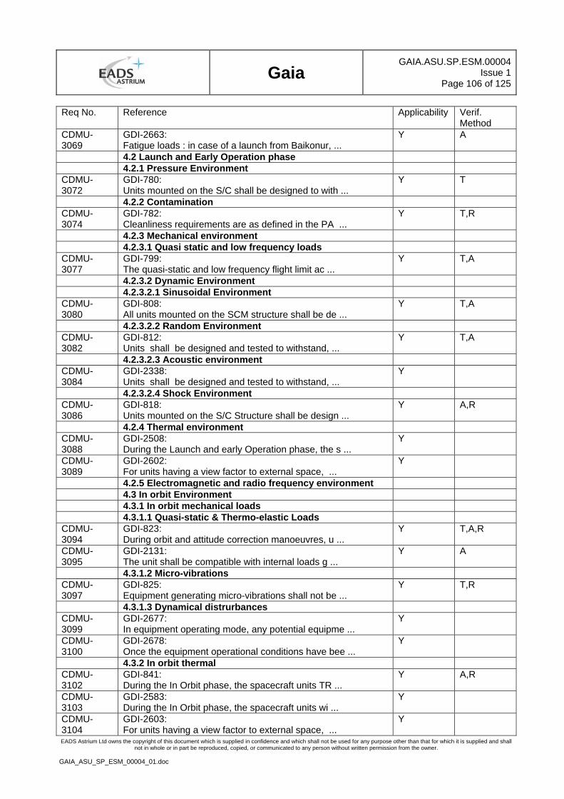
Gaia
GAIA.ASU.SP.ESM.00004Issue 1
Page 106 of 125
EADS Astrium Ltd owns the copyright of this document which is supplied in confidence and which shall not be used for any purpose other than that for which it is supplied and shall not in whole or in part be reproduced, copied, or communicated to any person without written permission from the owner.
GAIA_ASU_SP_ESM_00004_01.doc
Req No. Reference Applicability Verif. Method
CDMU-3069
GDI-2663: Fatigue loads : in case of a launch from Baikonur, ...
Y A
4.2 Launch and Early Operation phase 4.2.1 Pressure Environment CDMU-3072
GDI-780: Units mounted on the S/C shall be designed to with ...
Y T
4.2.2 Contamination CDMU-3074
GDI-782: Cleanliness requirements are as defined in the PA ...
Y T,R
4.2.3 Mechanical environment 4.2.3.1 Quasi static and low frequency loads CDMU-3077
GDI-799: The quasi-static and low frequency flight limit ac ...
Y T,A
4.2.3.2 Dynamic Environment 4.2.3.2.1 Sinusoidal Environment CDMU-3080
GDI-808: All units mounted on the SCM structure shall be de ...
Y T,A
4.2.3.2.2 Random Environment CDMU-3082
GDI-812: Units shall be designed and tested to withstand, ...
Y T,A
4.2.3.2.3 Acoustic environment CDMU-3084
GDI-2338: Units shall be designed and tested to withstand, ...
Y
4.2.3.2.4 Shock Environment CDMU-3086
GDI-818: Units mounted on the S/C Structure shall be design ...
Y A,R
4.2.4 Thermal environment CDMU-3088
GDI-2508: During the Launch and early Operation phase, the s ...
Y
CDMU-3089
GDI-2602: For units having a view factor to external space, ...
Y
4.2.5 Electromagnetic and radio frequency environment 4.3 In orbit Environment 4.3.1 In orbit mechanical loads 4.3.1.1 Quasi-static & Thermo-elastic Loads CDMU-3094
GDI-823: During orbit and attitude correction manoeuvres, u ...
Y T,A,R
CDMU-3095
GDI-2131: The unit shall be compatible with internal loads g ...
Y A
4.3.1.2 Micro-vibrations CDMU-3097
GDI-825: Equipment generating micro-vibrations shall not be ...
Y T,R
4.3.1.3 Dynamical distrurbances CDMU-3099
GDI-2677: In equipment operating mode, any potential equipme ...
Y
CDMU-3100
GDI-2678: Once the equipment operational conditions have bee ...
Y
4.3.2 In orbit thermal CDMU-3102
GDI-841: During the In Orbit phase, the spacecraft units TR ...
Y A,R
CDMU-3103
GDI-2583: During the In Orbit phase, the spacecraft units wi ...
Y
CDMU-3104
GDI-2603: For units having a view factor to external space, ...
Y
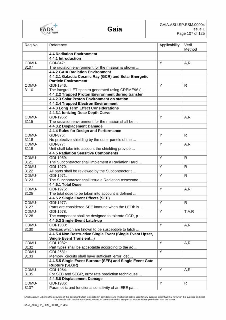
Gaia
GAIA.ASU.SP.ESM.00004Issue 1
Page 107 of 125
EADS Astrium Ltd owns the copyright of this document which is supplied in confidence and which shall not be used for any purpose other than that for which it is supplied and shall not in whole or in part be reproduced, copied, or communicated to any person without written permission from the owner.
GAIA_ASU_SP_ESM_00004_01.doc
Req No. Reference Applicability Verif. Method
4.4 Radiation Environment 4.4.1 Introduction CDMU-3107
GDI-847: The radiation environment for the mission is shown ...
Y A,R
4.4.2 GAIA Radiation Environment 4.4.2.1 Galactic Cosmic Ray (GCR) and Solar Energetic
Particle Environment
CDMU-3110
GDI-1946: The integral LET spectra generated using CREME96 ( ...
Y R
4.4.2.2 Trapped Proton Environment during transfer 4.4.2.3 Solar Proton Environment on station 4.4.2.4 Trapped Electron Environment 4.4.3 Long Term Effect Considerations 4.4.3.1 Ionizing Dose Depth Curve CDMU-3115
GDI-1966: The radiation environment for the mission shall be ...
Y A,R
4.4.3.2 Displacement Damage 4.4.4 Rules for Design and Performance CDMU-3118
GDI-876: No protective shielding by the outer panels of the ...
Y R
CDMU-3119
GDI-877: Unit shall take into account the shielding provide ...
Y A,R
4.4.5 Radiation Sensitive Components CDMU-3121
GDI-1969: The Subcontractor shall implement a Radiation Hard ...
Y R
CDMU-3122
GDI-1970: All parts shall be reviewed by the Subcontractor t ...
Y R
CDMU-3123
GDI-1971: The Subcontractor shall issue a Radiation Assessme ...
Y R
4.4.5.1 Total Dose CDMU-3125
GDI-1975: The total dose to be taken into account is defined ...
Y A,R
4.4.5.2 Single Event Effects (SEE) CDMU-3127
GDI-1977: Parts are considered SEE immune when the LETth is ...
Y R
CDMU-3128
GDI-1978: The component shall be designed to tolerate GCR, p ...
Y T,A,R
4.4.5.3 Single Event Latch-up CDMU-3130
GDI-1980: Devices which are known to be susceptible to latch ...
Y A,R
4.4.5.4 Non Destructive Single Event (Single Event Upset, Single Event Transient...)
CDMU-3132
GDI-1982: Part types shall be acceptable according to the ac ...
Y A,R
CDMU-3133
GDI-2681: Memory circuits shall have sufficient error det ...
Y
4.4.5.5 Single Event Burnout (SEB) and Single Event Gate Rupture (SEGR)
CDMU-3135
GDI-1984: For SEB and SEGR, error rate prediction techniques ...
Y A,R
4.4.5.6 Displacement Damage CDMU-3137
GDI-1986: Parametric and functional sensitivity of an EEE pa ...
Y R
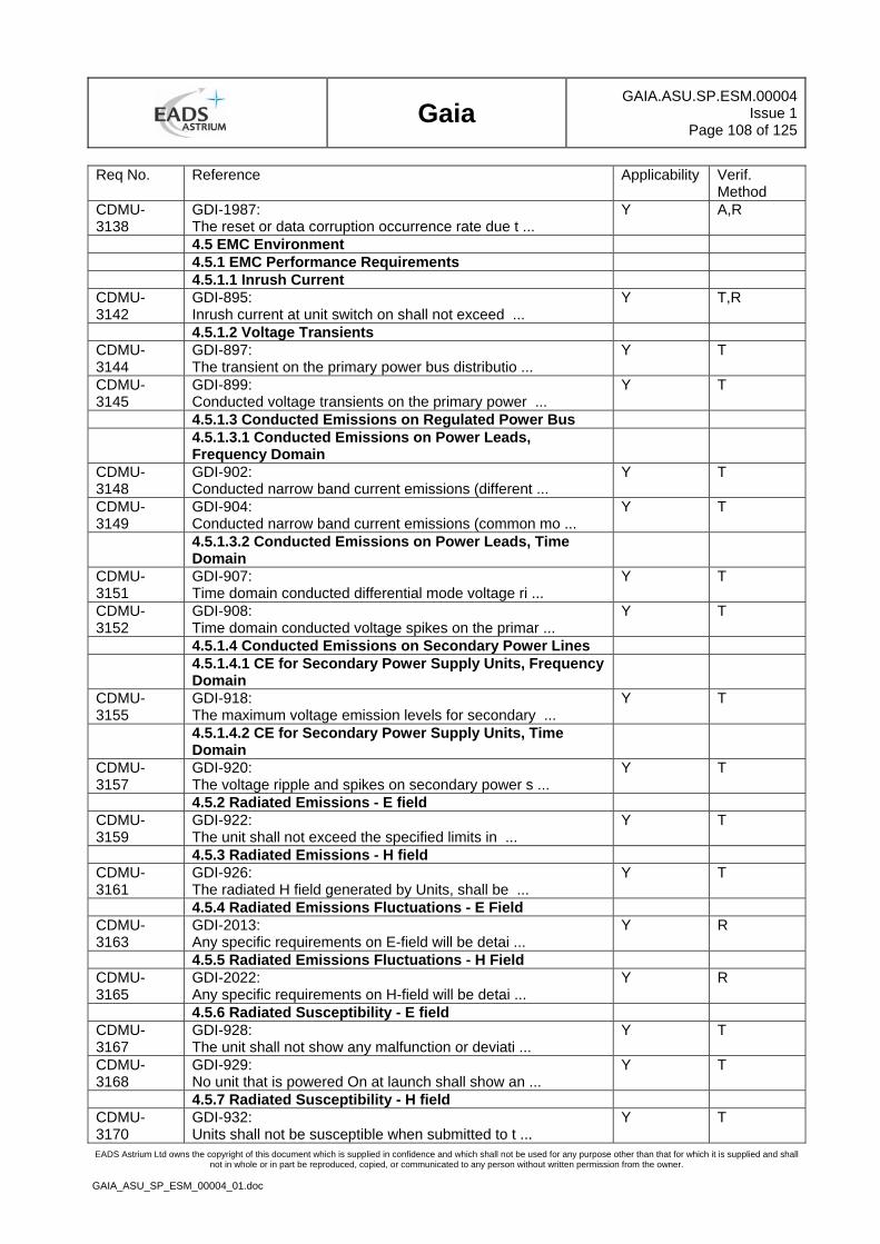
Gaia
GAIA.ASU.SP.ESM.00004Issue 1
Page 108 of 125
EADS Astrium Ltd owns the copyright of this document which is supplied in confidence and which shall not be used for any purpose other than that for which it is supplied and shall not in whole or in part be reproduced, copied, or communicated to any person without written permission from the owner.
GAIA_ASU_SP_ESM_00004_01.doc
Req No. Reference Applicability Verif. Method
CDMU-3138
GDI-1987: The reset or data corruption occurrence rate due t ...
Y A,R
4.5 EMC Environment 4.5.1 EMC Performance Requirements 4.5.1.1 Inrush Current CDMU-3142
GDI-895: Inrush current at unit switch on shall not exceed ...
Y T,R
4.5.1.2 Voltage Transients CDMU-3144
GDI-897: The transient on the primary power bus distributio ...
Y T
CDMU-3145
GDI-899: Conducted voltage transients on the primary power ...
Y T
4.5.1.3 Conducted Emissions on Regulated Power Bus 4.5.1.3.1 Conducted Emissions on Power Leads,
Frequency Domain
CDMU-3148
GDI-902: Conducted narrow band current emissions (different ...
Y T
CDMU-3149
GDI-904: Conducted narrow band current emissions (common mo ...
Y T
4.5.1.3.2 Conducted Emissions on Power Leads, Time Domain
CDMU-3151
GDI-907: Time domain conducted differential mode voltage ri ...
Y T
CDMU-3152
GDI-908: Time domain conducted voltage spikes on the primar ...
Y T
4.5.1.4 Conducted Emissions on Secondary Power Lines 4.5.1.4.1 CE for Secondary Power Supply Units, Frequency
Domain
CDMU-3155
GDI-918: The maximum voltage emission levels for secondary ...
Y T
4.5.1.4.2 CE for Secondary Power Supply Units, Time Domain
CDMU-3157
GDI-920: The voltage ripple and spikes on secondary power s ...
Y T
4.5.2 Radiated Emissions - E field CDMU-3159
GDI-922: The unit shall not exceed the specified limits in ...
Y T
4.5.3 Radiated Emissions - H field CDMU-3161
GDI-926: The radiated H field generated by Units, shall be ...
Y T
4.5.4 Radiated Emissions Fluctuations - E Field CDMU-3163
GDI-2013: Any specific requirements on E-field will be detai ...
Y R
4.5.5 Radiated Emissions Fluctuations - H Field CDMU-3165
GDI-2022: Any specific requirements on H-field will be detai ...
Y R
4.5.6 Radiated Susceptibility - E field CDMU-3167
GDI-928: The unit shall not show any malfunction or deviati ...
Y T
CDMU-3168
GDI-929: No unit that is powered On at launch shall show an ...
Y T
4.5.7 Radiated Susceptibility - H field CDMU-3170
GDI-932: Units shall not be susceptible when submitted to t ...
Y T
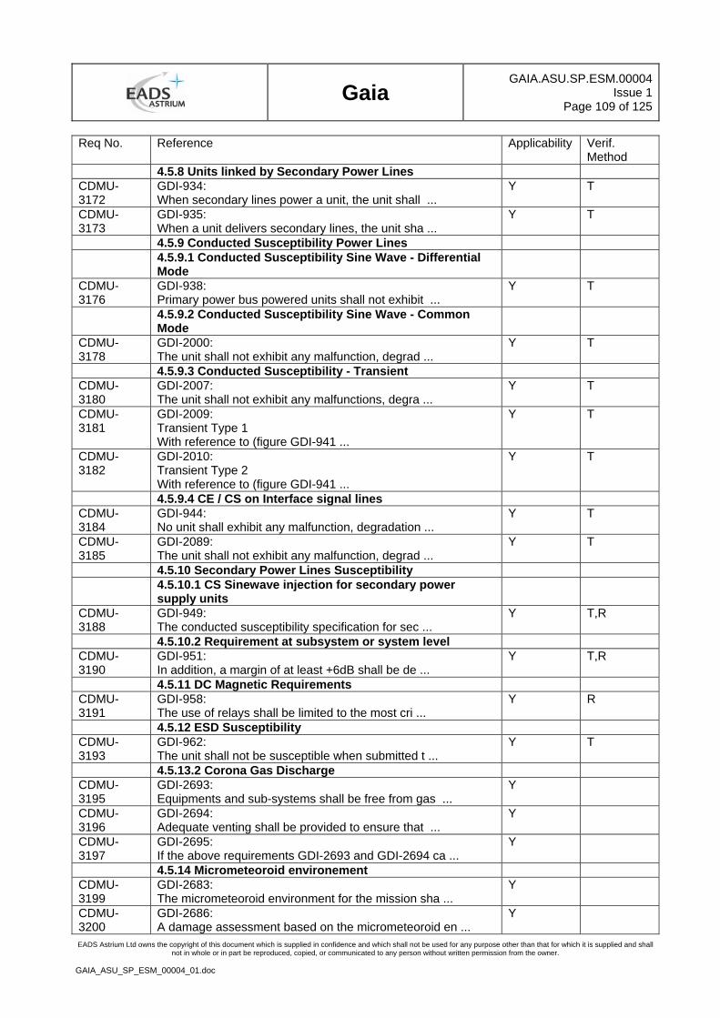
Gaia
GAIA.ASU.SP.ESM.00004Issue 1
Page 109 of 125
EADS Astrium Ltd owns the copyright of this document which is supplied in confidence and which shall not be used for any purpose other than that for which it is supplied and shall not in whole or in part be reproduced, copied, or communicated to any person without written permission from the owner.
GAIA_ASU_SP_ESM_00004_01.doc
Req No. Reference Applicability Verif. Method
4.5.8 Units linked by Secondary Power Lines CDMU-3172
GDI-934: When secondary lines power a unit, the unit shall ...
Y T
CDMU-3173
GDI-935: When a unit delivers secondary lines, the unit sha ...
Y T
4.5.9 Conducted Susceptibility Power Lines 4.5.9.1 Conducted Susceptibility Sine Wave - Differential
Mode
CDMU-3176
GDI-938: Primary power bus powered units shall not exhibit ...
Y T
4.5.9.2 Conducted Susceptibility Sine Wave - Common Mode
CDMU-3178
GDI-2000: The unit shall not exhibit any malfunction, degrad ...
Y T
4.5.9.3 Conducted Susceptibility - Transient CDMU-3180
GDI-2007: The unit shall not exhibit any malfunctions, degra ...
Y T
CDMU-3181
GDI-2009: Transient Type 1 With reference to (figure GDI-941 ...
Y T
CDMU-3182
GDI-2010: Transient Type 2 With reference to (figure GDI-941 ...
Y T
4.5.9.4 CE / CS on Interface signal lines CDMU-3184
GDI-944: No unit shall exhibit any malfunction, degradation ...
Y T
CDMU-3185
GDI-2089: The unit shall not exhibit any malfunction, degrad ...
Y T
4.5.10 Secondary Power Lines Susceptibility 4.5.10.1 CS Sinewave injection for secondary power
supply units
CDMU-3188
GDI-949: The conducted susceptibility specification for sec ...
Y T,R
4.5.10.2 Requirement at subsystem or system level CDMU-3190
GDI-951: In addition, a margin of at least +6dB shall be de ...
Y T,R
4.5.11 DC Magnetic Requirements CDMU-3191
GDI-958: The use of relays shall be limited to the most cri ...
Y R
4.5.12 ESD Susceptibility CDMU-3193
GDI-962: The unit shall not be susceptible when submitted t ...
Y T
4.5.13.2 Corona Gas Discharge CDMU-3195
GDI-2693: Equipments and sub-systems shall be free from gas ...
Y
CDMU-3196
GDI-2694: Adequate venting shall be provided to ensure that ...
Y
CDMU-3197
GDI-2695: If the above requirements GDI-2693 and GDI-2694 ca ...
Y
4.5.14 Micrometeoroid environement CDMU-3199
GDI-2683: The micrometeoroid environment for the mission sha ...
Y
CDMU-3200
GDI-2686: A damage assessment based on the micrometeoroid en ...
Y
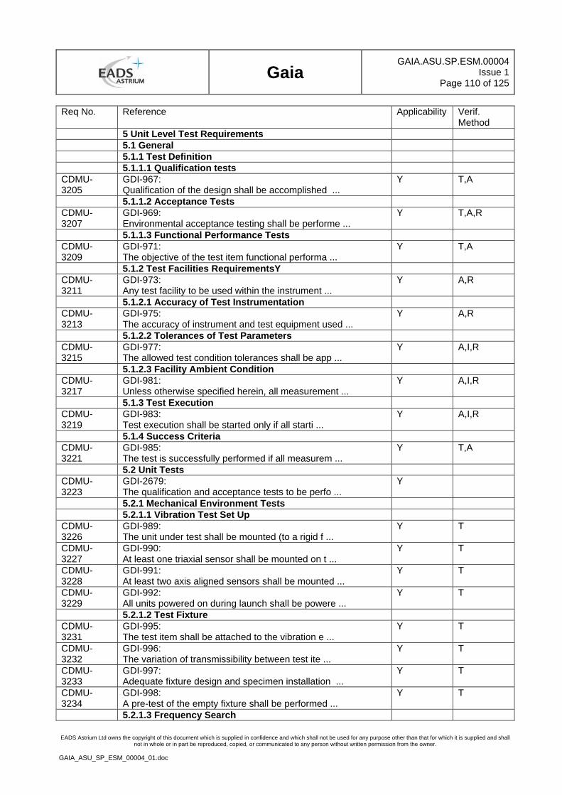
Gaia
GAIA.ASU.SP.ESM.00004Issue 1
Page 110 of 125
EADS Astrium Ltd owns the copyright of this document which is supplied in confidence and which shall not be used for any purpose other than that for which it is supplied and shall not in whole or in part be reproduced, copied, or communicated to any person without written permission from the owner.
GAIA_ASU_SP_ESM_00004_01.doc
Req No. Reference Applicability Verif. Method
5 Unit Level Test Requirements 5.1 General 5.1.1 Test Definition 5.1.1.1 Qualification tests CDMU-3205
GDI-967: Qualification of the design shall be accomplished ...
Y T,A
5.1.1.2 Acceptance Tests CDMU-3207
GDI-969: Environmental acceptance testing shall be performe ...
Y T,A,R
5.1.1.3 Functional Performance Tests CDMU-3209
GDI-971: The objective of the test item functional performa ...
Y T,A
5.1.2 Test Facilities RequirementsY CDMU-3211
GDI-973: Any test facility to be used within the instrument ...
Y A,R
5.1.2.1 Accuracy of Test Instrumentation CDMU-3213
GDI-975: The accuracy of instrument and test equipment used ...
Y A,R
5.1.2.2 Tolerances of Test Parameters CDMU-3215
GDI-977: The allowed test condition tolerances shall be app ...
Y A,I,R
5.1.2.3 Facility Ambient Condition CDMU-3217
GDI-981: Unless otherwise specified herein, all measurement ...
Y A,I,R
5.1.3 Test Execution CDMU-3219
GDI-983: Test execution shall be started only if all starti ...
Y A,I,R
5.1.4 Success Criteria CDMU-3221
GDI-985: The test is successfully performed if all measurem ...
Y T,A
5.2 Unit Tests CDMU-3223
GDI-2679: The qualification and acceptance tests to be perfo ...
Y
5.2.1 Mechanical Environment Tests 5.2.1.1 Vibration Test Set Up CDMU-3226
GDI-989: The unit under test shall be mounted (to a rigid f ...
Y T
CDMU-3227
GDI-990: At least one triaxial sensor shall be mounted on t ...
Y T
CDMU-3228
GDI-991: At least two axis aligned sensors shall be mounted ...
Y T
CDMU-3229
GDI-992: All units powered on during launch shall be powere ...
Y T
5.2.1.2 Test Fixture CDMU-3231
GDI-995: The test item shall be attached to the vibration e ...
Y T
CDMU-3232
GDI-996: The variation of transmissibility between test ite ...
Y T
CDMU-3233
GDI-997: Adequate fixture design and specimen installation ...
Y T
CDMU-3234
GDI-998: A pre-test of the empty fixture shall be performed ...
Y T
5.2.1.3 Frequency Search
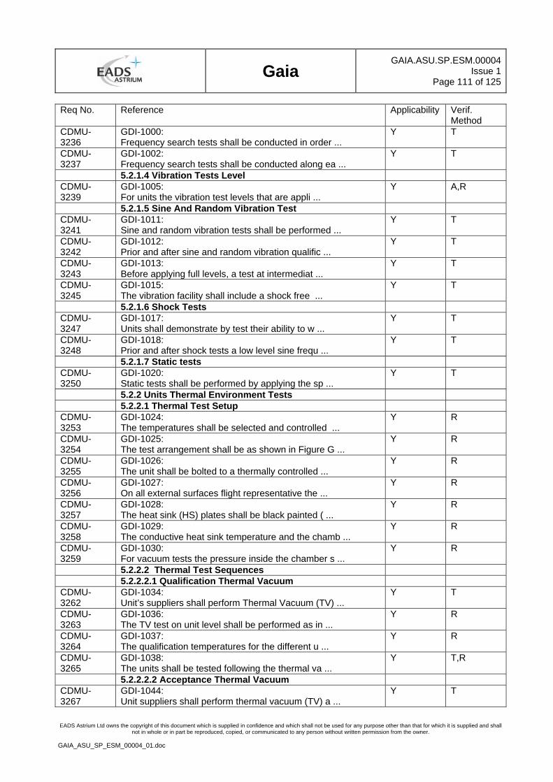
Gaia
GAIA.ASU.SP.ESM.00004Issue 1
Page 111 of 125
EADS Astrium Ltd owns the copyright of this document which is supplied in confidence and which shall not be used for any purpose other than that for which it is supplied and shall not in whole or in part be reproduced, copied, or communicated to any person without written permission from the owner.
GAIA_ASU_SP_ESM_00004_01.doc
Req No. Reference Applicability Verif. Method
CDMU-3236
GDI-1000: Frequency search tests shall be conducted in order ...
Y T
CDMU-3237
GDI-1002: Frequency search tests shall be conducted along ea ...
Y T
5.2.1.4 Vibration Tests Level CDMU-3239
GDI-1005: For units the vibration test levels that are appli ...
Y A,R
5.2.1.5 Sine And Random Vibration Test CDMU-3241
GDI-1011: Sine and random vibration tests shall be performed ...
Y T
CDMU-3242
GDI-1012: Prior and after sine and random vibration qualific ...
Y T
CDMU-3243
GDI-1013: Before applying full levels, a test at intermediat ...
Y T
CDMU-3245
GDI-1015: The vibration facility shall include a shock free ...
Y T
5.2.1.6 Shock Tests CDMU-3247
GDI-1017: Units shall demonstrate by test their ability to w ...
Y T
CDMU-3248
GDI-1018: Prior and after shock tests a low level sine frequ ...
Y T
5.2.1.7 Static tests CDMU-3250
GDI-1020: Static tests shall be performed by applying the sp ...
Y T
5.2.2 Units Thermal Environment Tests 5.2.2.1 Thermal Test Setup CDMU-3253
GDI-1024: The temperatures shall be selected and controlled ...
Y R
CDMU-3254
GDI-1025: The test arrangement shall be as shown in Figure G ...
Y R
CDMU-3255
GDI-1026: The unit shall be bolted to a thermally controlled ...
Y R
CDMU-3256
GDI-1027: On all external surfaces flight representative the ...
Y R
CDMU-3257
GDI-1028: The heat sink (HS) plates shall be black painted ( ...
Y R
CDMU-3258
GDI-1029: The conductive heat sink temperature and the chamb ...
Y R
CDMU-3259
GDI-1030: For vacuum tests the pressure inside the chamber s ...
Y R
5.2.2.2 Thermal Test Sequences 5.2.2.2.1 Qualification Thermal Vacuum CDMU-3262
GDI-1034: Unit’s suppliers shall perform Thermal Vacuum (TV) ...
Y T
CDMU-3263
GDI-1036: The TV test on unit level shall be performed as in ...
Y R
CDMU-3264
GDI-1037: The qualification temperatures for the different u ...
Y R
CDMU-3265
GDI-1038: The units shall be tested following the thermal va ...
Y T,R
5.2.2.2.2 Acceptance Thermal Vacuum CDMU-3267
GDI-1044: Unit suppliers shall perform thermal vacuum (TV) a ...
Y T
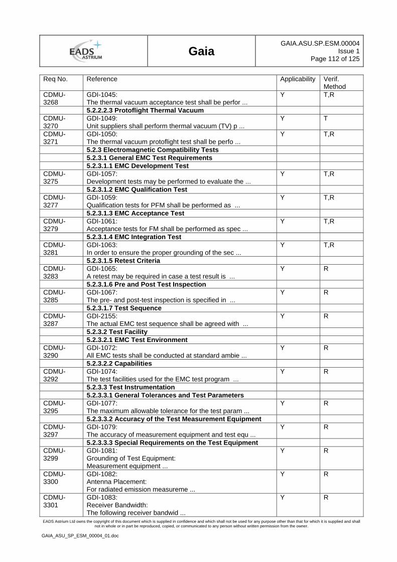
Gaia
GAIA.ASU.SP.ESM.00004Issue 1
Page 112 of 125
EADS Astrium Ltd owns the copyright of this document which is supplied in confidence and which shall not be used for any purpose other than that for which it is supplied and shall not in whole or in part be reproduced, copied, or communicated to any person without written permission from the owner.
GAIA_ASU_SP_ESM_00004_01.doc
Req No. Reference Applicability Verif. Method
CDMU-3268
GDI-1045: The thermal vacuum acceptance test shall be perfor ...
Y T,R
5.2.2.2.3 Protoflight Thermal Vacuum CDMU-3270
GDI-1049: Unit suppliers shall perform thermal vacuum (TV) p ...
Y T
CDMU-3271
GDI-1050: The thermal vacuum protoflight test shall be perfo ...
Y T,R
5.2.3 Electromagnetic Compatibility Tests 5.2.3.1 General EMC Test Requirements 5.2.3.1.1 EMC Development Test CDMU-3275
GDI-1057: Development tests may be performed to evaluate the ...
Y T,R
5.2.3.1.2 EMC Qualification Test CDMU-3277
GDI-1059: Qualification tests for PFM shall be performed as ...
Y T,R
5.2.3.1.3 EMC Acceptance Test CDMU-3279
GDI-1061: Acceptance tests for FM shall be performed as spec ...
Y T,R
5.2.3.1.4 EMC Integration Test CDMU-3281
GDI-1063: In order to ensure the proper grounding of the sec ...
Y T,R
5.2.3.1.5 Retest Criteria CDMU-3283
GDI-1065: A retest may be required in case a test result is ...
Y R
5.2.3.1.6 Pre and Post Test Inspection CDMU-3285
GDI-1067: The pre- and post-test inspection is specified in ...
Y R
5.2.3.1.7 Test Sequence CDMU-3287
GDI-2155: The actual EMC test sequence shall be agreed with ...
Y R
5.2.3.2 Test Facility 5.2.3.2.1 EMC Test Environment CDMU-3290
GDI-1072: All EMC tests shall be conducted at standard ambie ...
Y R
5.2.3.2.2 Capabilities CDMU-3292
GDI-1074: The test facilities used for the EMC test program ...
Y R
5.2.3.3 Test Instrumentation 5.2.3.3.1 General Tolerances and Test Parameters CDMU-3295
GDI-1077: The maximum allowable tolerance for the test param ...
Y R
5.2.3.3.2 Accuracy of the Test Measurement Equipment CDMU-3297
GDI-1079: The accuracy of measurement equipment and test equ ...
Y R
5.2.3.3.3 Special Requirements on the Test Equipment CDMU-3299
GDI-1081: Grounding of Test Equipment: Measurement equipment ...
Y R
CDMU-3300
GDI-1082: Antenna Placement: For radiated emission measureme ...
Y R
CDMU-3301
GDI-1083: Receiver Bandwidth: The following receiver bandwid ...
Y R
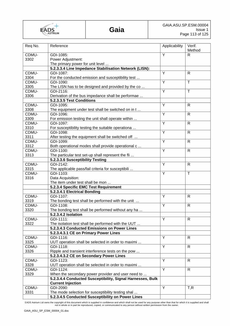
Gaia
GAIA.ASU.SP.ESM.00004Issue 1
Page 113 of 125
EADS Astrium Ltd owns the copyright of this document which is supplied in confidence and which shall not be used for any purpose other than that for which it is supplied and shall not in whole or in part be reproduced, copied, or communicated to any person without written permission from the owner.
GAIA_ASU_SP_ESM_00004_01.doc
Req No. Reference Applicability Verif. Method
CDMU-3302
GDI-1085: Power Adjustment: The primary power for unit level ...
Y R
5.2.3.3.4 Line Impedance Stabilisation Network (LISN): CDMU-3304
GDI-1087: For the conducted emission and susceptibility test ...
Y R
CDMU-3305
GDI-1090: The LISN has to be designed and provided by the co ...
Y T
CDMU-3306
GDI-2116: Derivation of the bus impedance shall be performae ...
Y T
5.2.3.3.5 Test Conditions CDMU-3308
GDI-1095: The equipment under test shall be switched on in t ...
Y R
CDMU-3309
GDI-1096: For emission testing the unit shall operate within ...
Y R
CDMU-3310
GDI-1097: For susceptibility testing the suitable operationa ...
Y R
CDMU-3311
GDI-1098: After testing the equipment shall be switched off ...
Y R
CDMU-3312
GDI-1099: Both operational modes shall provide operational c ...
Y R
CDMU-3313
GDI-1100: The particular test set-up shall represent the fli ...
Y R
5.2.3.3.6 Susceptibility Testing CDMU-3315
GDI-2142: The applicable pass/fail criteria for susceptibili ...
Y R
CDMU-3316
GDI-1103: Data Acquisition: The item under test shall be mon ...
Y T
5.2.3.4 Specific EMC Test Requirement 5.2.3.4.1 Electrical Bonding CDMU-3319
GDI-1107: The bonding test shall be performed with the unit ...
Y R
CDMU-3320
GDI-1108: The bonding test shall be performed without any ha ...
Y R
5.2.3.4.2 Isolation CDMU-3322
GDI-1111: The isolation test shall be performed with the UUT ...
Y R
5.2.3.4.3 Conducted Emissions on Power Lines 5.2.3.4.3.1 CE on Primary Power Lines CDMU-3325
GDI-1116: UUT operation shall be selected in order to maximi ...
Y R
CDMU-3326
GDI-1118: Ripple and transient interference tests on the pow ...
Y R
5.2.3.4.3.2 CE on Secondary Power Lines CDMU-3328
GDI-1123: UUT operation shall be selected in order to maximi ...
Y R
CDMU-3329
GDI-1124: When the secondary power provider and user need to ...
Y R
5.2.3.4.4 Conducted Susceptibility, Signal Harnesses, Bulk Current Injection
CDMU-3331
GDI-2090: The mode selection for susceptibility testing shal ...
Y T,R
5.2.3.4.5 Conducted Susceptibility on Power Lines
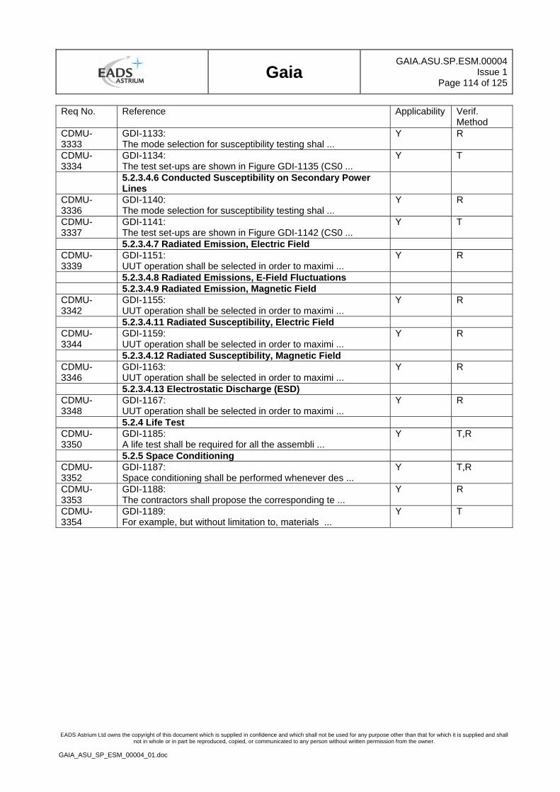
Gaia
GAIA.ASU.SP.ESM.00004Issue 1
Page 114 of 125
EADS Astrium Ltd owns the copyright of this document which is supplied in confidence and which shall not be used for any purpose other than that for which it is supplied and shall not in whole or in part be reproduced, copied, or communicated to any person without written permission from the owner.
GAIA_ASU_SP_ESM_00004_01.doc
Req No. Reference Applicability Verif. Method
CDMU-3333
GDI-1133: The mode selection for susceptibility testing shal ...
Y R
CDMU-3334
GDI-1134: The test set-ups are shown in Figure GDI-1135 (CS0 ...
Y T
5.2.3.4.6 Conducted Susceptibility on Secondary Power Lines
CDMU-3336
GDI-1140: The mode selection for susceptibility testing shal ...
Y R
CDMU-3337
GDI-1141: The test set-ups are shown in Figure GDI-1142 (CS0 ...
Y T
5.2.3.4.7 Radiated Emission, Electric Field CDMU-3339
GDI-1151: UUT operation shall be selected in order to maximi ...
Y R
5.2.3.4.8 Radiated Emissions, E-Field Fluctuations 5.2.3.4.9 Radiated Emission, Magnetic Field CDMU-3342
GDI-1155: UUT operation shall be selected in order to maximi ...
Y R
5.2.3.4.11 Radiated Susceptibility, Electric Field CDMU-3344
GDI-1159: UUT operation shall be selected in order to maximi ...
Y R
5.2.3.4.12 Radiated Susceptibility, Magnetic Field CDMU-3346
GDI-1163: UUT operation shall be selected in order to maximi ...
Y R
5.2.3.4.13 Electrostatic Discharge (ESD) CDMU-3348
GDI-1167: UUT operation shall be selected in order to maximi ...
Y R
5.2.4 Life Test CDMU-3350
GDI-1185: A life test shall be required for all the assembli ...
Y T,R
5.2.5 Space Conditioning CDMU-3352
GDI-1187: Space conditioning shall be performed whenever des ...
Y T,R
CDMU-3353
GDI-1188: The contractors shall propose the corresponding te ...
Y R
CDMU-3354
GDI-1189: For example, but without limitation to, materials ...
Y T
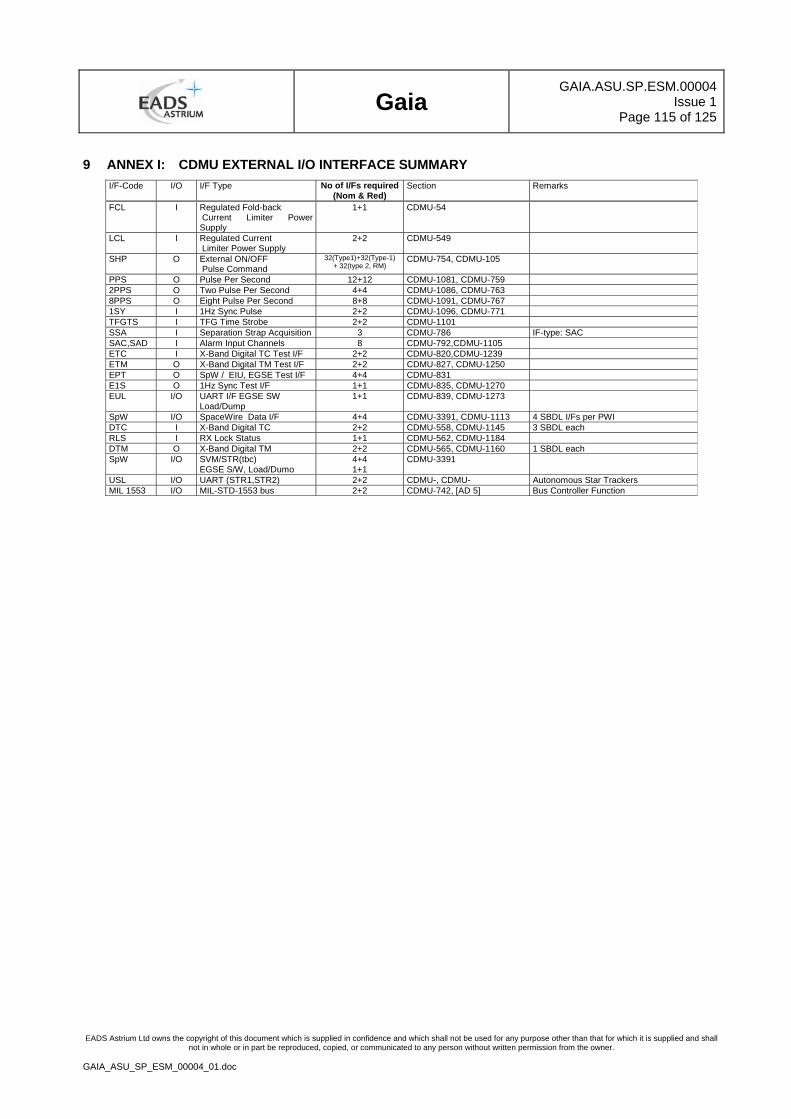
Gaia
GAIA.ASU.SP.ESM.00004Issue 1
Page 115 of 125
EADS Astrium Ltd owns the copyright of this document which is supplied in confidence and which shall not be used for any purpose other than that for which it is supplied and shall not in whole or in part be reproduced, copied, or communicated to any person without written permission from the owner.
GAIA_ASU_SP_ESM_00004_01.doc
9 ANNEX I: CDMU EXTERNAL I/O INTERFACE SUMMARY I/F-Code I/O I/F Type No of I/Fs required
(Nom & Red) Section Remarks
FCL I Regulated Fold-back Current Limiter Power Supply
1+1 CDMU-54
LCL I Regulated Current Limiter Power Supply
2+2 CDMU-549
SHP O External ON/OFF Pulse Command
32(Type1)+32(Type-1) + 32(type 2, RM)
CDMU-754, CDMU-105
PPS O Pulse Per Second 12+12 CDMU-1081, CDMU-759 2PPS O Two Pulse Per Second 4+4 CDMU-1086, CDMU-763 8PPS O Eight Pulse Per Second 8+8 CDMU-1091, CDMU-767 1SY I 1Hz Sync Pulse 2+2 CDMU-1096, CDMU-771 TFGTS I TFG Time Strobe 2+2 CDMU-1101 SSA I Separation Strap Acquisition 3 CDMU-786 IF-type: SAC SAC,SAD I Alarm Input Channels 8 CDMU-792,CDMU-1105 ETC I X-Band Digital TC Test I/F 2+2 CDMU-820,CDMU-1239 ETM O X-Band Digital TM Test I/F 2+2 CDMU-827, CDMU-1250 EPT O SpW / EIU, EGSE Test I/F 4+4 CDMU-831 E1S O 1Hz Sync Test I/F 1+1 CDMU-835, CDMU-1270 EUL I/O UART I/F EGSE SW
Load/Dump 1+1 CDMU-839, CDMU-1273
SpW I/O SpaceWire Data I/F 4+4 CDMU-3391, CDMU-1113 4 SBDL I/Fs per PWI DTC I X-Band Digital TC 2+2 CDMU-558, CDMU-1145 3 SBDL each RLS I RX Lock Status 1+1 CDMU-562, CDMU-1184 DTM O X-Band Digital TM 2+2 CDMU-565, CDMU-1160 1 SBDL each SpW I/O SVM/STR(tbc)
EGSE S/W, Load/Dumo 4+4 1+1
CDMU-3391
USL I/O UART (STR1,STR2) 2+2 CDMU-, CDMU- Autonomous Star Trackers MIL 1553 I/O MIL-STD-1553 bus 2+2 CDMU-742, [AD 5] Bus Controller Function
Gaia
GAIA.ASU.SP.ESM.00004Issue 1
Page 116 of 125
EADS Astrium Ltd owns the copyright of this document which is supplied in confidence and which shall not be used for any purpose other than that for which it is supplied and shall not in whole or in part be reproduced, copied, or communicated to any person without written permission from the owner.
GAIA_ASU_SP_ESM_00004_01.doc
10 ANNEX II: TYPICAL CDMU EXTERNAL ON/OFF (SHP) ALLOCATION (TBC)
Gaia
GAIA.ASU.SP.ESM.00004Issue 1
Page 117 of 125
EADS Astrium Ltd owns the copyright of this document which is supplied in confidence and which shall not be used for any purpose other than that for which it is supplied and shall not in whole or in part be reproduced, copied, or communicated to any person without written permission from the owner.
GAIA_ASU_SP_ESM_00004_01.doc
11 ANNEX III: SIMULATION MODEL DATA REQUIREMENTS
CDMU-1397/CREATED/
The Model based development approach requires a full software simulation of the CDMU. This will be implemented with a level of fidelity which allows it to run the unmodified API and Application Software in the simulated CDMU.
CDMU-1398/CREATED/
Therefore the detailed description with regard to Hardware/ Software Interfaces and the functional behaviour of the CDMU submodules shall be delivered by the contractor.
CDMU-1399/CREATED/
The subcontractor shall deliver documentation which details the impact of any software instruction with respect to the external CDMU interfaces or behaviour of the CDMU.
Gaia
GAIA.ASU.SP.ESM.00004Issue 1
Page 118 of 125
EADS Astrium Ltd owns the copyright of this document which is supplied in confidence and which shall not be used for any purpose other than that for which it is supplied and shall not in whole or in part be reproduced, copied, or communicated to any person without written permission from the owner.
GAIA_ASU_SP_ESM_00004_01.doc
12 ABBREVIATIONS LIST
AIT Assembly, Integration & Test
AOCS Attitude Orbit Control System
API Application Program Interface
APID Application Identifier
Bat Battery
BCC Battery Charge Controller
BDC Battery Discharge Controller
BSW Basic Software
CDMU Control and Data Management Unit
CDU Clock Distribution Unit
CLCW Command Link Control Word.
CLK Clock
CLTU Command Line Transimssion Unit
CPDU Command Pulse Distribution Unit
DNEL Disconnect non-essential loads
CPU Central Processor Unit
EGSE Electrical Ground Special Equipment
EIU Equipment Interface Unit
EPC Electronic Power Converter
EEPROM Electrical Eraseable Programmable Read Only Memory
FAAD Flight Attitude Anomaly Detector
EPS Electrical Power System
FCL Foldback Current Limiter (EPS outlet)
FDIR Failure Detection Isolation and Recovery
HK Housekeeping
HPC High Priority Command (ON/OFF)
HPC-type 1 High Priority Command from Ground(Via TC Decoder)
HPC-type 2 High Priority Command from Reconfiguration Module
HPC-type 3 High Priority Command from EIU I/O Module
HTR Heater
ICB Internal Control Bus
LCL Latching current limiter (EPS outlet)
LV Latch Valve
LVDS Low Voltage Differential Signalling
MAP Multiplexed Access Points - see ESA PSS 04-107
MIL_A Nominal Milbus
MIL_B Redundant Milbus
Gaia
GAIA.ASU.SP.ESM.00004Issue 1
Page 119 of 125
EADS Astrium Ltd owns the copyright of this document which is supplied in confidence and which shall not be used for any purpose other than that for which it is supplied and shall not in whole or in part be reproduced, copied, or communicated to any person without written permission from the owner.
GAIA_ASU_SP_ESM_00004_01.doc
MilBus MIL-STD 1553 B
Mod Modulator
MMU Mass Memory Unit
OBCP On Board Control Procedure
OBDH On Board Data Handling
OOL Out Of Limit
PCDU Power Control and Distribution Unit
PDHU Payload Data Handling Unit
PDT Payload Data Transmission
PM Processor Module
PPS Pulse per Second
PLM Payload Module
PROM Programmable Read Only Memory
PWR Power
RAM Random Access Memory
RCS Reaction Control System
RM Reconfiguration Module
RS Reed Soloman
RT Remote Terminal
RTC Real Time Clock
RX Receiver
SC Spacecraft
SCET Spacecraft Elapsed Timer
SGM Safe Guard Memory
SSMM Solid State Mass Memory
SHP Standard High Power
SEU Single Event Upset
SpW Spacewire
SPARD SW Product Assurance Requirement Document
SSPA Solid State Power Amplifier
STSP Standard Time Source Packets
SUSW Start Up Software
SVT System Validation Test
SVM Service Module
TBC To Be Confirmed
TBD To Be Defined
TCS Thermal Control System
TFG Transfer Frame Generator
Gaia
GAIA.ASU.SP.ESM.00004Issue 1
Page 120 of 125
EADS Astrium Ltd owns the copyright of this document which is supplied in confidence and which shall not be used for any purpose other than that for which it is supplied and shall not in whole or in part be reproduced, copied, or communicated to any person without written permission from the owner.
GAIA_ASU_SP_ESM_00004_01.doc
TIF Transponder Interface Function
TM/TC TeleMetry /TeleCommand
TRSP Transponder
TTR TM/TC/RM (board in CDMU)
TX Transmitter
UART Universal Asynchroneous Receiver Transmitter
UTC Unsegmented Time Code
VC Virtual Channel
WD Watch Dog
XBS X-Band System
Gaia
GAIA.ASU.SP.ESM.00004Issue 1
Page 121 of 125
EADS Astrium Ltd owns the copyright of this document which is supplied in confidence and which shall not be used for any purpose other than that for which it is supplied and shall not in whole or in part be reproduced, copied, or communicated to any person without written permission from the owner.
GAIA_ASU_SP_ESM_00004_01.doc
Requirement/Section Cross Reference Page numbers are the pages where the sections start
CDMU-130 ......... 3.1....................9 CDMU-131 ......... 3.1....................9 CDMU-132 ......... 3.1....................9 CDMU-134 ......... 3.1....................9 CDMU-135 ......... 3.1....................9 CDMU-136 ......... 3.1....................9 CDMU-137 ......... 3.1....................9 CDMU-138 ......... 3.1....................9 CDMU-140 ......... 3.1....................9 CDMU-141 ......... 3.1....................9 CDMU-142 ......... 3.1....................9 CDMU-143 ......... 3.1....................9 CDMU-144 ......... 3.1....................9 CDMU-145 ......... 3.1....................9 CDMU-146 ......... 3.1....................9 CDMU-147 ......... 3.1....................9 CDMU-149 ......... 3.1....................9 CDMU-150 ......... 3.1....................9 CDMU-151 ......... 3.1....................9 CDMU-152 ......... 3.1....................9 CDMU-153 ......... 3.1....................9 CDMU-154 ......... 3.1....................9 CDMU-156 ......... 3.1....................9 CDMU-157 ......... 3.1....................9 CDMU-158 ......... 3.1....................9 CDMU-159 ......... 3.1....................9 CDMU-160 ......... 3.1....................9 CDMU-161 ......... 3.1....................9 CDMU-162 ......... 3.1....................9 CDMU-163 ......... 3.1....................9 CDMU-166 ......... 3.1....................9 CDMU-169 ......... 3.2.1.................12 CDMU-170 ......... 3.2.1.................12 CDMU-171 ......... 3.2.1.................12 CDMU-172 ......... 3.2.1.................12 CDMU-174 ......... 3.2.2.................13 CDMU-175 ......... 3.2.2.................13 CDMU-176 ......... 3.2.2.................13 CDMU-177 ......... 3.2.2.................13 CDMU-178 ......... 3.2.2.................13 CDMU-179 ......... 3.2.2.................13 CDMU-182 ......... 3.2.3.1..............13 CDMU-183 ......... 3.2.3.1..............13 CDMU-184 ......... 3.2.3.1..............13 CDMU-185 ......... 3.2.3.1..............13 CDMU-186 ......... 3.2.3.1..............13 CDMU-187 ......... 3.2.3.1..............13 CDMU-191 ......... 3.2.3.2..............14 CDMU-192 ......... 3.2.3.2..............14 CDMU-194 ......... 3.2.3.3..............15 CDMU-195 ......... 3.2.3.3..............15 CDMU-196 ......... 3.2.3.3..............15 CDMU-197 ......... 3.2.3.3..............15 CDMU-198 ......... 3.2.3.3..............15 CDMU-199 ......... 3.2.3.3..............15 CDMU-200 ......... 3.2.3.3..............15 CDMU-201 ......... 3.2.3.3..............15
CDMU-202 ..........3.2.3.3 ............. 15 CDMU-203 ..........3.2.3.3 ............. 15 CDMU-204 ..........3.2.3.3 ............. 15 CDMU-205 ..........3.2.3.3 ............. 15 CDMU-206 ..........3.2.3.3 ............. 15 CDMU-208 ..........3.2.3.3 ............. 15 CDMU-209 ..........3.2.3.3 ............. 15 CDMU-210 ..........3.2.3.3 ............. 15 CDMU-211 ..........3.2.3.3 ............. 15 CDMU-212 ..........3.2.3.3 ............. 15 CDMU-213 ..........3.2.3.3 ............. 15 CDMU-214 ..........3.2.3.3 ............. 15 CDMU-215 ..........3.2.3.3 ............. 15 CDMU-216 ..........3.2.3.3 ............. 15 CDMU-217 ..........3.2.3.3 ............. 15 CDMU-218 ..........3.2.3.3 ............. 15 CDMU-219 ..........3.2.3.3 ............. 15 CDMU-220 ..........3.2.3.3 ............. 15 CDMU-221 ..........3.2.3.3 ............. 15 CDMU-222 ..........3.2.3.3 ............. 15 CDMU-223 ..........3.2.3.3 ............. 15 CDMU-224 ..........3.2.3.3 ............. 15 CDMU-226 ..........3.2.3.4 ............. 18 CDMU-227 ..........3.2.3.4 ............. 18 CDMU-228 ..........3.2.3.4 ............. 18 CDMU-229 ..........3.2.3.4 ............. 18 CDMU-230 ..........3.2.3.4 ............. 18 CDMU-231 ..........3.2.3.4 ............. 18 CDMU-232 ..........3.2.3.4 ............. 18 CDMU-233 ..........3.2.3.4 ............. 18 CDMU-234 ..........3.2.3.4 ............. 18 CDMU-235 ..........3.2.3.4 ............. 18 CDMU-236 ..........3.2.3.4 ............. 18 CDMU-237 ..........3.2.3.4 ............. 18 CDMU-238 ..........3.2.3.4 ............. 18 CDMU-239 ..........3.2.3.4 ............. 18 CDMU-240 ..........3.2.3.4 ............. 18 CDMU-241 ..........3.2.3.4 ............. 18 CDMU-242 ..........3.2.3.4 ............. 18 CDMU-243 ..........3.2.3.4 ............. 18 CDMU-244 ..........3.2.3.4 ............. 18 CDMU-245 ..........3.2.3.4 ............. 18 CDMU-246 ..........3.2.3.4 ............. 18 CDMU-248 ..........3.2.3.4 ............. 18 CDMU-249 ..........3.2.3.4 ............. 18 CDMU-250 ..........3.2.3.4 ............. 18 CDMU-251 ..........3.2.3.4 ............. 18 CDMU-252 ..........3.2.3.4 ............. 18 CDMU-253 ..........3.2.3.4 ............. 18 CDMU-254 ..........3.2.3.4 ............. 18 CDMU-255 ..........3.2.3.4 ............. 18 CDMU-257 ..........3.2.3.4 ............. 18 CDMU-258 ..........3.2.3.4 ............. 18 CDMU-259 ..........3.2.3.4 ............. 18 CDMU-261 ..........3.2.3.4 ............. 18 CDMU-263 ..........3.2.3.5 ............. 22 CDMU-264 ..........3.2.3.5 ............. 22
CDMU-266.......... 3.2.4 .................22 CDMU-268.......... 3.2.4.1 ..............22 CDMU-270.......... 3.2.4.1 ..............22 CDMU-272.......... 3.2.4.2 ..............23 CDMU-273.......... 3.2.4.2 ..............23 CDMU-274.......... 3.2.4.2 ..............23 CDMU-275.......... 3.2.4.2 ..............23 CDMU-276.......... 3.2.4.2 ..............23 CDMU-277.......... 3.2.4.2 ..............23 CDMU-278.......... 3.2.4.2 ..............23 CDMU-279.......... 3.2.4.2 ..............23 CDMU-282.......... 3.2.4.3 ..............23 CDMU-283.......... 3.2.4.3 ..............23 CDMU-284.......... 3.2.4.3 ..............23 CDMU-285.......... 3.2.4.3 ..............23 CDMU-286.......... 3.2.4.3 ..............23 CDMU-287.......... 3.2.4.3 ..............23 CDMU-288.......... 3.2.4.3 ..............23 CDMU-290.......... 3.2.4.4 ..............24 CDMU-291.......... 3.2.4.4 ..............24 CDMU-292.......... 3.2.4.4 ..............24 CDMU-293.......... 3.2.4.4 ..............24 CDMU-294.......... 3.2.4.4 ..............24 CDMU-295.......... 3.2.4.4 ..............24 CDMU-296.......... 3.2.4.4 ..............24 CDMU-298.......... 3.2.4.5 ..............25 CDMU-299.......... 3.2.4.5 ..............25 CDMU-300.......... 3.2.4.5 ..............25 CDMU-301.......... 3.2.4.5 ..............25 CDMU-302.......... 3.2.4.5 ..............25 CDMU-303.......... 3.2.4.5 ..............25 CDMU-304.......... 3.2.4.5 ..............25 CDMU-305.......... 3.2.4.5 ..............25 CDMU-306.......... 3.2.4.5 ..............25 CDMU-307.......... 3.2.4.5 ..............25 CDMU-309.......... 3.2.4.6 ..............25 CDMU-310.......... 3.2.4.6 ..............25 CDMU-314.......... 3.2.4.7 ..............26 CDMU-317.......... 3.2.4.7.1 ...........26 CDMU-319.......... 3.2.4.7.1 ...........26 CDMU-320.......... 3.2.4.7.1 ...........26 CDMU-321.......... 3.2.4.7.1 ...........26 CDMU-322.......... 3.2.4.7.1 ...........26 CDMU-323.......... 3.2.4.7.1 ...........26 CDMU-324.......... 3.2.4.7.1 ...........26 CDMU-325.......... 3.2.4.7.1 ...........26 CDMU-326.......... 3.2.4.7.1 ...........26 CDMU-328.......... 3.2.4.7.2 ...........27 CDMU-329.......... 3.2.4.7.2 ...........27 CDMU-330.......... 3.2.4.7.2 ...........27 CDMU-331.......... 3.2.4.7.2 ...........27 CDMU-332.......... 3.2.4.7.2 ...........27 CDMU-333.......... 3.2.4.7.2 ...........27 CDMU-334.......... 3.2.4.7.2 ...........27 CDMU-335.......... 3.2.4.7.2 ...........27 CDMU-336.......... 3.2.4.7.2 ...........27 CDMU-339.......... 3.2.5.1 ..............28
Gaia
GAIA.ASU.SP.ESM.00004Issue 1
Page 122 of 125
EADS Astrium Ltd owns the copyright of this document which is supplied in confidence and which shall not be used for any purpose other than that for which it is supplied and shall not in whole or in part be reproduced, copied, or communicated to any person without written permission from the owner.
GAIA_ASU_SP_ESM_00004_01.doc
CDMU-341 ......... 3.2.5.1..............28 CDMU-342 ......... 3.2.5.1..............28 CDMU-343 ......... 3.2.5.1..............28 CDMU-344 ......... 3.2.5.1..............28 CDMU-345 ......... 3.2.5.1..............28 CDMU-347 ......... 3.2.5.2..............28 CDMU-348 ......... 3.2.5.2..............28 CDMU-349 ......... 3.2.5.2..............28 CDMU-350 ......... 3.2.5.2..............28 CDMU-351 ......... 3.2.5.2..............28 CDMU-355 ......... 3.2.5.3..............29 CDMU-356 ......... 3.2.5.3..............29 CDMU-357 ......... 3.2.5.3..............29 CDMU-358 ......... 3.2.5.3..............29 CDMU-359 ......... 3.2.5.3..............29 CDMU-360 ......... 3.2.5.3..............29 CDMU-361 ......... 3.2.5.3..............29 CDMU-362 ......... 3.2.5.3..............29 CDMU-363 ......... 3.2.5.3..............29 CDMU-364 ......... 3.2.5.3..............29 CDMU-366 ......... 3.2.5.3..............29 CDMU-367 ......... 3.2.5.3..............29 CDMU-368 ......... 3.2.5.3..............29 CDMU-369 ......... 3.2.5.3..............29 CDMU-370 ......... 3.2.5.3..............29 CDMU-371 ......... 3.2.5.3..............29 CDMU-372 ......... 3.2.5.3..............29 CDMU-373 ......... 3.2.5.3..............29 CDMU-374 ......... 3.2.5.3..............29 CDMU-375 ......... 3.2.5.3..............29 CDMU-376 ......... 3.2.5.3..............29 CDMU-377 ......... 3.2.5.3..............29 CDMU-379 ......... 3.2.5.3..............29 CDMU-380 ......... 3.2.5.3..............29 CDMU-381 ......... 3.2.5.3..............29 CDMU-382 ......... 3.2.5.3..............29 CDMU-383 ......... 3.2.5.3..............29 CDMU-384 ......... 3.2.5.3..............29 CDMU-385 ......... 3.2.5.3..............29 CDMU-386 ......... 3.2.5.3..............29 CDMU-388 ......... 3.2.5.3..............29 CDMU-389 ......... 3.2.5.3..............29 CDMU-390 ......... 3.2.5.3..............29 CDMU-391 ......... 3.2.5.3..............29 CDMU-392 ......... 3.2.5.3..............29 CDMU-393 ......... 3.2.5.3..............29 CDMU-394 ......... 3.2.5.3..............29 CDMU-395 ......... 3.2.5.3..............29 CDMU-396 ......... 3.2.5.3..............29 CDMU-397 ......... 3.2.5.3..............29 CDMU-398 ......... 3.2.5.3..............29 CDMU-403 ......... 3.2.5.4..............32 CDMU-405 ......... 3.2.5.5..............33 CDMU-406 ......... 3.2.5.5..............33 CDMU-407 ......... 3.2.5.5..............33 CDMU-408 ......... 3.2.5.5..............33 CDMU-410 ......... 3.2.5.6..............33 CDMU-414 ......... 3.2.5.7..............33 CDMU-416 ......... 3.2.5.7..............33 CDMU-418 ......... 3.2.5.7..............33
CDMU-419 ..........3.2.5.7 ............. 33 CDMU-420 ..........3.2.5.7 ............. 33 CDMU-421 ..........3.2.5.7 ............. 33 CDMU-422 ..........3.2.5.7 ............. 33 CDMU-423 ..........3.2.5.7 ............. 33 CDMU-424 ..........3.2.5.7 ............. 33 CDMU-425 ..........3.2.5.7 ............. 33 CDMU-426 ..........3.2.5.7 ............. 33 CDMU-431 ..........3.2.6.1 ............. 34 CDMU-432 ..........3.2.6.1 ............. 34 CDMU-433 ..........3.2.6.1 ............. 34 CDMU-434 ..........3.2.6.1 ............. 34 CDMU-435 ..........3.2.6.1 ............. 34 CDMU-436 ..........3.2.6.1 ............. 34 CDMU-437 ..........3.2.6.1 ............. 34 CDMU-438 ..........3.2.6.1 ............. 34 CDMU-439 ..........3.2.6.1 ............. 34 CDMU-440 ..........3.2.6.1 ............. 34 CDMU-442 ..........3.2.6.1 ............. 34 CDMU-443 ..........3.2.6.1 ............. 34 CDMU-444 ..........3.2.6.1 ............. 34 CDMU-445 ..........3.2.6.1 ............. 34 CDMU-446 ..........3.2.6.1 ............. 34 CDMU-447 ..........3.2.6.1 ............. 34 CDMU-448 ..........3.2.6.1 ............. 34 CDMU-449 ..........3.2.6.1 ............. 34 CDMU-450 ..........3.2.6.1 ............. 34 CDMU-451 ..........3.2.6.1 ............. 34 CDMU-453 ..........3.2.6.1 ............. 34 CDMU-485 ..........3.2.7 ................ 36 CDMU-486 ..........3.2.7 ................ 36 CDMU-489 ..........3.2.7 ................ 36 CDMU-490 ..........3.2.7 ................ 36 CDMU-491 ..........3.2.7 ................ 36 CDMU-492 ..........3.2.7 ................ 36 CDMU-493 ..........3.2.7 ................ 36 CDMU-494 ..........3.2.7 ................ 36 CDMU-497 ..........3.2.7 ................ 36 CDMU-498 ..........3.2.7 ................ 36 CDMU-501 ..........3.2.7 ................ 36 CDMU-502 ..........3.2.7 ................ 36 CDMU-503 ..........3.2.7 ................ 36 CDMU-504 ..........3.2.7 ................ 36 CDMU-505 ..........3.2.7 ................ 36 CDMU-506 ..........3.2.7 ................ 36 CDMU-507 ..........3.2.7 ................ 36 CDMU-508 ..........3.2.7 ................ 36 CDMU-509 ..........3.2.7 ................ 36 CDMU-510 ..........3.2.7 ................ 36 CDMU-511 ..........3.2.7 ................ 36 CDMU-512 ..........3.2.7 ................ 36 CDMU-513 ..........3.2.7 ................ 36 CDMU-514 ..........3.2.7 ................ 36 CDMU-515 ..........3.2.7 ................ 36 CDMU-516 ..........3.2.7 ................ 36 CDMU-519 ..........3.3.1 ................ 40 CDMU-521 ..........3.3.2 ................ 40 CDMU-522 ..........3.3.2 ................ 40 CDMU-524 ..........3.3.3 ................ 40 CDMU-525 ..........3.3.3 ................ 40
CDMU-526.......... 3.3.3 .................40 CDMU-527.......... 3.3.3 .................40 CDMU-528.......... 3.3.3 .................40 CDMU-530.......... 3.3.4 .................41 CDMU-531.......... 3.3.4 .................41 CDMU-532.......... 3.3.4 .................41 CDMU-533.......... 3.3.4 .................41 CDMU-534.......... 3.3.4 .................41 CDMU-535.......... 3.3.4 .................41 CDMU-539.......... 3.3.5 .................41 CDMU-540.......... 3.3.5 .................41 CDMU-542.......... 3.3.7 .................42 CDMU-543.......... 3.3.7 .................42 CDMU-544.......... 3.3.7 .................42 CDMU-545.......... 3.3.7 .................42 CDMU-549.......... 3.4.1 .................44 CDMU-551.......... 3.4.1 .................44 CDMU-552.......... 3.4.1 .................44 CDMU-559.......... 3.4.2.1 ..............46 CDMU-560.......... 3.4.2.1 ..............46 CDMU-561.......... 3.4.2.1 ..............46 CDMU-563.......... 3.4.2.2 ..............46 CDMU-564.......... 3.4.2.2 ..............46 CDMU-566.......... 3.4.2.3 ..............47 CDMU-567.......... 3.4.2.3 ..............47 CDMU-568.......... 3.4.2.3 ..............47 CDMU-744.......... 3.4.3.1 ..............47 CDMU-745.......... 3.4.3.1 ..............47 CDMU-746.......... 3.4.3.1 ..............47 CDMU-747.......... 3.4.3.1 ..............47 CDMU-748.......... 3.4.3.1 ..............47 CDMU-749.......... 3.4.3.1 ..............47 CDMU-750.......... 3.4.3.1 ..............47 CDMU-751.......... 3.4.3.1 ..............47 CDMU-752.......... 3.4.3.1 ..............47 CDMU-754.......... 3.4.3.3 ..............49 CDMU-755.......... 3.4.3.3 ..............49 CDMU-760.......... 3.4.3.4 ..............49 CDMU-761.......... 3.4.3.4 ..............49 CDMU-762.......... 3.4.3.4 ..............49 CDMU-764.......... 3.4.3.5 ..............49 CDMU-765.......... 3.4.3.5 ..............49 CDMU-766.......... 3.4.3.5 ..............49 CDMU-768.......... 3.4.3.6 ..............49 CDMU-769.......... 3.4.3.6 ..............49 CDMU-770.......... 3.4.3.6 ..............49 CDMU-772.......... 3.4.3.7 ..............50 CDMU-773.......... 3.4.3.7 ..............50 CDMU-774.......... 3.4.3.7 ..............50 CDMU-776.......... 3.4.3.8 ..............50 CDMU-777.......... 3.4.3.8 ..............50 CDMU-778.......... 3.4.3.8 ..............50 CDMU-786.......... 3.4.3.9 ..............50 CDMU-787.......... 3.4.3.9 ..............50 CDMU-788.......... 3.4.3.9 ..............50 CDMU-789.......... 3.4.3.9 ..............50 CDMU-790.......... 3.4.3.9 ..............50 CDMU-791.......... 3.4.3.9 ..............50 CDMU-793.......... 3.4.3.10 ............51 CDMU-794.......... 3.4.3.10 ............51
Gaia
GAIA.ASU.SP.ESM.00004Issue 1
Page 123 of 125
EADS Astrium Ltd owns the copyright of this document which is supplied in confidence and which shall not be used for any purpose other than that for which it is supplied and shall not in whole or in part be reproduced, copied, or communicated to any person without written permission from the owner.
GAIA_ASU_SP_ESM_00004_01.doc
CDMU-795 ......... 3.4.3.10............51 CDMU-816 ......... 3.4.3.11.1.........51 CDMU-817 ......... 3.4.3.11.1.........51 CDMU-818 ......... 3.4.3.11.1.........51 CDMU-819 ......... 3.4.3.11.1.........51 CDMU-821 ......... 3.4.3.11.2.........51 CDMU-822 ......... 3.4.3.11.2.........51 CDMU-823 ......... 3.4.3.11.2.........51 CDMU-824 ......... 3.4.3.11.2.........51 CDMU-825 ......... 3.4.3.11.2.........51 CDMU-826 ......... 3.4.3.11.2.........51 CDMU-828 ......... 3.4.3.11.3.........52 CDMU-829 ......... 3.4.3.11.3.........52 CDMU-830 ......... 3.4.3.11.3.........52 CDMU-836 ......... 3.4.3.11.4.........52 CDMU-837 ......... 3.4.3.11.4.........52 CDMU-838 ......... 3.4.3.11.4.........52 CDMU-840 ......... 3.4.3.11.5.........52 CDMU-841 ......... 3.4.3.11.5.........52 CDMU-842 ......... 3.4.3.11.5.........52 CDMU-844 ......... 3.4.4.................53 CDMU-846 ......... 3.4.4.................53 CDMU-858 ......... 3.5....................53 CDMU-859 ......... 3.5....................53 CDMU-861 ......... 3.5.1.1..............53 CDMU-862 ......... 3.5.1.3..............55 CDMU-863 ......... 3.5.1.3..............55 CDMU-864 ......... 3.5.1.3..............55 CDMU-865 ......... 3.5.1.3..............55 CDMU-866 ......... 3.5.1.1..............53 CDMU-867 ......... 3.5.1.1..............53 CDMU-868 ......... 3.5.1.3.1...........56 CDMU-869 ......... 3.5.1.4..............59 CDMU-871 ......... 3.5.1.3.2...........57 CDMU-873 ......... 3.5.1.3.2...........57 CDMU-874 ......... 3.5.1.8..............61 CDMU-875 ......... 3.5.1.8..............61 CDMU-876 ......... 3.5.1.5..............59 CDMU-879 ......... 3.5.2.................61 CDMU-880 ......... 3.5.2.................61 CDMU-881 ......... 3.5.2.................61 CDMU-882 ......... 3.5.2.................61 CDMU-883 ......... 3.5.2.................61 CDMU-884 ......... 3.5.2.................61 CDMU-885 ......... 3.5.2.................61 CDMU-886 ......... 3.5.2.................61 CDMU-887 ......... 3.5.2.................61 CDMU-889 ......... 3.5.2.................61 CDMU-892 ......... 3.5.3.................63 CDMU-893 ......... 3.5.3.................63 CDMU-894 ......... 3.5.3.................63 CDMU-895 ......... 3.5.3.................63 CDMU-896 ......... 3.5.3.................63 CDMU-897 ......... 3.5.3.................63 CDMU-900 ......... 3.5.4.1..............64 CDMU-901 ......... 3.5.4.1..............64 CDMU-902 ......... 3.5.4.1..............64 CDMU-903 ......... 3.5.4.1..............64 CDMU-904 ......... 3.5.4.1..............64 CDMU-905 ......... 3.5.4.1..............64
CDMU-907 ..........3.5.4.2 ............. 64 CDMU-909 ..........3.5.4.3 ............. 65 CDMU-910 ..........3.5.4.3 ............. 65 CDMU-911 ..........3.5.4.3 ............. 65 CDMU-913 ..........3.5.4.4 ............. 65 CDMU-914 ..........3.5.4.4 ............. 65 CDMU-915 ..........3.5.4.4 ............. 65 CDMU-917 ..........3.5.4.5 ............. 65 CDMU-918 ..........3.5.4.5 ............. 65 CDMU-919 ..........3.5.4.5 ............. 65 CDMU-921 ..........3.5.5 ................ 65 CDMU-922 ..........3.5.5 ................ 65 CDMU-923 ..........3.5.5 ................ 65 CDMU-924 ..........3.5.5 ................ 65 CDMU-926 ..........3.5.5 ................ 65 CDMU-927 ..........3.5.5 ................ 65 CDMU-928 ..........3.5.5 ................ 65 CDMU-930 ..........3.5.5 ................ 65 CDMU-931 ..........3.5.5 ................ 65 CDMU-932 ..........3.5.5 ................ 65 CDMU-933 ..........3.5.5 ................ 65 CDMU-935 ..........3.5.6 ................ 66 CDMU-939 ..........3.6.1.1 ............. 67 CDMU-940 ..........3.6.1.1 ............. 67 CDMU-941 ..........3.6.1.1 ............. 67 CDMU-942 ..........3.6.1.1 ............. 67 CDMU-946 ..........3.6.1.2 ............. 67 CDMU-949 ..........3.6.2.1 ............. 68 CDMU-950 ..........3.6.2.1 ............. 68 CDMU-951 ..........3.6.2.1 ............. 68 CDMU-952 ..........3.6.2.1 ............. 68 CDMU-953 ..........3.6.2.1 ............. 68 CDMU-956 ..........3.6.2.2 ............. 68 CDMU-957 ..........3.6.2.2 ............. 68 CDMU-959 ..........3.6.2.3 ............. 69 CDMU-960 ..........3.6.2.3 ............. 69 CDMU-961 ..........3.6.2.3 ............. 69 CDMU-962 ..........3.6.2.3 ............. 69 CDMU-963 ..........3.6.2.3 ............. 69 CDMU-965 ..........3.7 ................... 69 CDMU-966 ..........3.7 ................... 69 CDMU-967 ..........3.7 ................... 69 CDMU-968 ..........3.7 ................... 69 CDMU-969 ..........3.7 ................... 69 CDMU-970 ..........3.7 ................... 69 CDMU-971 ..........3.7 ................... 69 CDMU-972 ..........3.7 ................... 69 CDMU-973 ..........3.7 ................... 69 CDMU-980 ..........4.1.1 ................ 71 CDMU-982 ..........4.1.2 ................ 71 CDMU-984 ..........4.1.3 ................ 71 CDMU-987 ..........4.2.1 ................ 71 CDMU-989 ..........4.2.2 ................ 71 CDMU-991 ..........4.2.3 ................ 72 CDMU-1083 ........4.3.1.1 ............. 72 CDMU-1084 ........4.3.1.1 ............. 72 CDMU-1088 ........4.3.1.2 ............. 73 CDMU-1089 ........4.3.1.2 ............. 73 CDMU-1093 ........4.3.1.3 ............. 73 CDMU-1094 ........4.3.1.3 ............. 73
CDMU-1098........ 4.3.1.4 ..............73 CDMU-1099........ 4.3.1.4 ..............73 CDMU-1102........ 4.3.1.5 ..............73 CDMU-1106........ 4.3.1.6 ..............73 CDMU-1107........ 4.3.1.6 ..............73 CDMU-1109........ 4.3.1.6 ..............73 CDMU-1110........ 4.3.1.6 ..............73 CDMU-1112........ 4.3.1.6 ..............73 CDMU-1230........ 4.3.2 .................75 CDMU-1231........ 4.3.2 .................75 CDMU-1238........ 4.3.2 .................75 CDMU-1259........ 4.3.2.1 ..............75 CDMU-1260........ 4.3.2.1 ..............75 CDMU-1262........ 4.3.2.1 ..............75 CDMU-1269........ 4.3.2.1 ..............75 CDMU-1271........ 4.3.2.2 ..............76 CDMU-1285........ 5.2.1 .................77 CDMU-1287........ 5.2.2 .................77 CDMU-1288........ 5.2.2 .................77 CDMU-1289........ 5.2.2 .................77 CDMU-1290........ 5.2.2 .................77 CDMU-1291........ 5.2.2 .................77 CDMU-1293........ 5.2.3 .................77 CDMU-1295........ 5.2.4 .................77 CDMU-1296........ 5.2.4 .................77 CDMU-1297........ 5.2.4 .................77 CDMU-1298........ 5.2.4 .................77 CDMU-1299........ 5.2.4 .................77 CDMU-1300........ 5.2.4 .................77 CDMU-1301........ 5.2.4 .................77 CDMU-1302........ 5.2.4 .................77 CDMU-1303........ 5.2.4 .................77 CDMU-1304........ 5.2.4 .................77 CDMU-1305........ 5.2.4 .................77 CDMU-1307........ 5.3 ....................79 CDMU-1308........ 5.3 ....................79 CDMU-1310........ 5.3 ....................79 CDMU-1312........ 5.4 ....................79 CDMU-1314........ 6 .......................80 CDMU-1315........ 6 .......................80 CDMU-1321........ 7.1.1 .................81 CDMU-1322........ 7.1.1 .................81 CDMU-1397........ 11 .....................117 CDMU-1398........ 11 .....................117 CDMU-1399........ 11 .....................117 CDMU-2073........ 3.2.7 .................36 CDMU-2075........ 3.2.7 .................36 CDMU-2082........ 3.3.6 .................41 CDMU-2083........ 3.3.6 .................41 CDMU-2084........ 3.3.6 .................41 CDMU-2085........ 3.3.6 .................41 CDMU-2086........ 3.3.6 .................41 CDMU-2087........ 3.3.6 .................41 CDMU-2096........ 3.1 ....................9 CDMU-2099........ 3.2.2 .................13 CDMU-2100........ 3.2.3.3 ..............15 CDMU-2101........ 3.2.3.3 ..............15 CDMU-2102........ 3.2.4.6 ..............25 CDMU-2104........ 3.2.5.3 ..............29 CDMU-2105........ 3.2.5.5 ..............33
Gaia
GAIA.ASU.SP.ESM.00004Issue 1
Page 124 of 125
EADS Astrium Ltd owns the copyright of this document which is supplied in confidence and which shall not be used for any purpose other than that for which it is supplied and shall not in whole or in part be reproduced, copied, or communicated to any person without written permission from the owner.
GAIA_ASU_SP_ESM_00004_01.doc
CDMU-2175 ....... 3.5.1.1..............53 CDMU-2176 ....... 3.5.1.2..............55 CDMU-2179 ....... 3.5.1.2..............55 CDMU-2180 ....... 3.5.1.2..............55 CDMU-2181 ....... 3.5.1.2..............55 CDMU-2182 ....... 3.5.1.2..............55 CDMU-2183 ....... 3.5.1.2..............55 CDMU-2185 ....... 3.5.1.1..............53 CDMU-2186 ....... 3.5.1.1..............53 CDMU-2187 ....... 3.5.1.3.1...........56 CDMU-2188 ....... 3.5.1.3.1...........56 CDMU-2189 ....... 3.5.1.3.1...........56 CDMU-2191 ....... 3.5.1.3.1...........56 CDMU-2194 ....... 3.5.1.3.1...........56 CDMU-2195 ....... 3.5.1.3.2...........57 CDMU-2201 ....... 3.5.1.3.2...........57 CDMU-2202 ....... 3.5.1.3.2...........57 CDMU-2204 ....... 3.5.1.3.2...........57 CDMU-2206 ....... 3.5.1.3.2...........57 CDMU-2207 ....... 3.5.1.3.2...........57 CDMU-2208 ....... 3.5.1.3.2...........57 CDMU-2209 ....... 3.5.1.3.2...........57 CDMU-2210 ....... 3.5.1.3.2...........57 CDMU-2211 ....... 3.5.1.3.2...........57 CDMU-2212 ....... 3.5.1.1..............53 CDMU-2213 ....... 3.5.1.3.2...........57 CDMU-2214 ....... 3.5.1.3.2...........57 CDMU-2215 ....... 3.5.1.3.2...........57 CDMU-2216 ....... 3.5.1.3.2...........57 CDMU-2218 ....... 3.5.1.4..............59 CDMU-2219 ....... 3.5.1.4..............59 CDMU-2220 ....... 3.5.1.4..............59 CDMU-2222 ....... 3.5.1.4..............59 CDMU-2223 ....... 3.5.1.4..............59 CDMU-2228 ....... 3.5.1.5..............59 CDMU-2229 ....... 3.5.1.5..............59 CDMU-2230 ....... 3.5.1.1..............53 CDMU-2231 ....... 3.5.1.3.2...........57 CDMU-2232 ....... 3.5.1.5..............59 CDMU-2233 ....... 3.5.1.1..............53 CDMU-2234 ....... 3.5.1.5..............59 CDMU-2235 ....... 3.5.1.5..............59 CDMU-2236 ....... 3.5.1.5..............59 CDMU-2237 ....... 3.5.1.5..............59 CDMU-2238 ....... 3.5.1.5..............59 CDMU-2239 ....... 3.5.1.5..............59 CDMU-2240 ....... 3.5.1.6..............60 CDMU-2241 ....... 3.5.1.6..............60 CDMU-2242 ....... 3.5.1.6..............60 CDMU-2243 ....... 3.5.1.7..............60 CDMU-2244 ....... 3.5.1.7..............60 CDMU-2246 ....... 3.5.1.7..............60 CDMU-2247 ....... 3.5.1.7..............60 CDMU-2248 ....... 3.5.1.7..............60 CDMU-2287 ....... 3.2.3.3..............15 CDMU-2288 ....... 3.2.3.3..............15 CDMU-2289 ....... 3.2.3.3..............15 CDMU-2290 ....... 3.2.3.4..............18 CDMU-2291 ....... 3.2.3.4..............18 CDMU-2292 ....... 3.2.3.4..............18
CDMU-2295 ........3.2.4.6 ............. 25 CDMU-2296 ........3.2.4.6 ............. 25 CDMU-2297 ........3.2.4.7.2 .......... 27 CDMU-2298 ........5.4 ................... 79 CDMU-2306 ........5.5 ................... 79 CDMU-2307 ........5.6 ................... 79 CDMU-2308 ........5.7 ................... 79 CDMU-2310 ........5.8 ................... 79 CDMU-2312 ........5.4 ................... 79 CDMU-2313 ........5.1 ................... 77 CDMU-2319 ........3.2.4.3 ............. 23 CDMU-2320 ........3.2.7 ................ 36 CDMU-2321 ........3.2.7 ................ 36 CDMU-2322 ........3.2.7 ................ 36 CDMU-2325 ........3.4.1 ................ 44 CDMU-2326 ........3.4.4 ................ 53 CDMU-2328 ........3.4.4 ................ 53 CDMU-2329 ........3.2.4.7.2 .......... 27 CDMU-2330 ........3.5.1.1 ............. 53 CDMU-2332 ........3.5.1.9 ............. 61 CDMU-2333 ........3.5.2 ................ 61 CDMU-2334 ........3.5.1.9 ............. 61 CDMU-2335 ........3.5.1.9 ............. 61 CDMU-2337 ........3.2.6.2 ............. 36 CDMU-2340 ........3.2.3.4 ............. 18 CDMU-2341 ........3.2.3.4 ............. 18 CDMU-2342 ........3.2.3.4 ............. 18 CDMU-2343 ........3.2.3.4 ............. 18 CDMU-2344 ........3.2.3.4 ............. 18 CDMU-2345 ........3.2.3.4 ............. 18 CDMU-2346 ........3.2.3.4 ............. 18 CDMU-2347 ........3.2.3.4 ............. 18 CDMU-2348 ........3.2.3.4 ............. 18 CDMU-2349 ........4.2.2 ................ 71 CDMU-3377 ........3.2.7 ................ 36 CDMU-3378 ........3.4.2.3 ............. 47 CDMU-3379 ........3.4.3.11.4 ........ 52 CDMU-3380 ........3.4.4 ................ 53 CDMU-3381 ........3.2.7 ................ 36 CDMU-3382 ........3.2.4.7.2 .......... 27 CDMU-3386 ........3.4.4 ................ 53 CDMU-3387 ........3.2.4.7.2 .......... 27 CDMU-3388 ........3.4.1 ................ 44 CDMU-3389 ........3.4.3.1 ............. 47 CDMU-3391 ........3.4.3.2 ............. 48 CDMU-3392 ........3.4.3.2 ............. 48 CDMU-3393 ........3.4.3.2 ............. 48 CDMU-3394 ........3.4.3.2 ............. 48 CDMU-3395 ........3.4.3.2 ............. 48 CDMU-3396 ........3.4.3.2 ............. 48 CDMU-3397 ........3.2.3.3 ............. 15 CDMU-3398 ........3.2.3.3 ............. 15 CDMU-3399 ........3.2.6.1 ............. 34 CDMU-3400 ........3.3.6 ................ 41 CDMU-3401 ........3.3.6 ................ 41 CDMU-3402 ........3.3.6 ................ 41 CDMU-3403 ........3.3.7 ................ 42 CDMU-3404 ........3.3.7 ................ 42 CDMU-3405 ........3.3.7 ................ 42 CDMU-3406 ........3.2.3.4 ............. 18
CDMU-3407........ 3.2.5.7 ..............33 CDMU-3408........ 3.2.5.7 ..............33 CDMU-3409........ 3.3.6 .................41 CDMU-3410........ 3.5.1.5 ..............59 CDMU-3411........ 3.5.2 .................61 CDMU-3412........ 3.5.3 .................63 CDMU-3413........ 3.5.4.5 ..............65 CDMU-3414........ 3.2.7 .................36 CDMU-3415........ 3.2.4.5 ..............25 CDMU-3416........ 3.2.3.3 ..............15 CDMU-3417........ 3.2.3.4 ..............18 CDMU-3418........ 3.2.7 .................36 CDMU-3419........ 4.2.2 .................71 CDMU-3420........ 4.2.2 .................71 CDMU-3421........ 4.2.2 .................71 CDMU-3422........ 4.2.2 .................71 CDMU-3423........ 4.2.2 .................71 CDMU-3424........ 5.2.3 .................77 CDMU-3427........ 3.2.6.1 ..............34 CDMU-3430........ 3.2.6.2 ..............36 CDMU-3431........ 3.4.2.3 ..............47 CDMU-3434........ 3.5.2 .................61 CDMU-3435........ 3.5.2 .................61 CDMU-3436........ 3.5.2 .................61 CDMU-3437........ 3.4.3.2 ..............48 CDMU-3438........ 3.1 ....................9 CDMU-3439........ 3.2.6.1 ..............34 CDMU-3440........ 3.2.6.1 ..............34 CDMU-3441........ 3.2.6.1 ..............34 CDMU-3442........ 3.4.3.10 ............51 CDMU-3443........ 3.4.3.10 ............51 CDMU-3444........ 3.2.6.1 ..............34 CDMU-3445........ 3.5.2 .................61 CDMU-3446........ 3.5.2 .................61 CDMU-3448........ 3.4.3.2 ..............48 CDMU-3449........ 3.4.3.2 ..............48 CDMU-3450........ 3.2.4.6 ..............25 CDMU-3451........ 3.4.3.9 ..............50 CDMU-3452........ 3.1 ....................9 CDMU-3639........ 3.2.6.1 ..............34
Gaia
GAIA.ASU.SP.ESM.00004Issue 1
Page 125 of 125
EADS Astrium Ltd owns the copyright of this document which is supplied in confidence and which shall not be used for any purpose other than that for which it is supplied and shall not in whole or in part be reproduced, copied, or communicated to any person without written permission from the owner.
GAIA_ASU_SP_ESM_00004_01.doc
DOCUMENT CHANGE DETAILS
ISSUE CHANGE AUTHORITY CLASS RELEVANT INFORMATION/INSTRUCTIONS
1 Initial Issue
DISTRIBUTION LIST
INTERNAL EXTERNAL
Configuration Management