Embed Size (px)
Citation preview


Gaia Ref : GAIA.ASF.TCN.CSW.00019
Issue : 01 Rev. : 00 Date : 07/04/2006 Page : ii
NbCars 43871 NbWords 8015 FileName GAIA.ASF.TCN.CSW.00019.doc
© EADS/Astrium
Page intentionally left blank

Gaia Ref : GAIA.ASF.TCN.CSW.00019
Issue : 01 Rev. : 00 Date : 07/04/2006 Page : iii
NbCars 43871 NbWords 8015 FileName GAIA.ASF.TCN.CSW.00019.doc
© EADS/Astrium
SUMMARY
An Electrically Erasable Programmable Read Only Memory (EEPROM) is rewritable. This brings the operational flexibility for the uplink of software patches or large modifications to the flight software code via ground commands. A Hitachi 1-Mbit EEPROM die - HCN58C1001 - is packaged by various vendors (Maxwell, Austin) into various space-qualified EEPROM packages and used in many US and EU space projects. EEPROM data retention failures were reported by space missions. On 25 August 2005, the NASA advisory NA-GSFC-2005-04 reported failures centred on systems based on the Hitachi die: “weak cells” are pointed out as the intermediate cause of failure, thus shortening the data retention lifetime. Failures range from single bit programmed with “0” and read back as a “1” (discharged state) to 128-byte page corruption. The root failure mechanism leading to “weak cells” remain unknown. It is believed that “weak cells” are due to process-induced or programming defects. Screening on device vendor level allows eliminating faulty items. However, as fault cause(s) might also be extrinsic (e.g., programming, circuit design), the occurrence of an EEPROM data retention failure in flight cannot be discarded. High temperature and high number of erase/write cycles increase the data retention degradation. Ratings that shall not be exceeded have been highlighted by Maxwell. The mitigation solutions are applied to Gaia on different levels:
• Component level. • Circuit design level. • System level. • Flight operations level.
These solutions are inspired from dispositions recommended by device manufacturers, the NASA advisory, EADS EEE committee and other projects like Pléiades and Aeolus. As options may conflict with other requirements – e.g., n-plication of images vs. memory margin requirement – additional solutions are proposed to reconcile EEPROM issue resolution and Gaia mission requirements.
Document controlled by

Gaia Ref : GAIA.ASF.TCN.CSW.00019
Issue : 01 Rev. : 00 Date : 07/04/2006 Page : iv
NbCars 43871 NbWords 8015 FileName GAIA.ASF.TCN.CSW.00019.doc
© EADS/Astrium
DOCUMENT CHANGE LOG
Issue/
Revision Date Modification Nb Modified pages Observations
01/00 07/04/06 Original issue

Gaia Ref : GAIA.ASF.TCN.CSW.00019
Issue : 01 Rev. : 00 Date : 07/04/2006 Page : v
(GAIA.ASF.TCN.CSW.00019.doc)
TABLE OF CONTENTS
1 SCOPE AND APPLICABILITY......................................................................................................................... 1
2 RELEVANT DOCUMENTATION................................................................................................................... 1
3 GAIA SYSTEM REQUIREMENTS RELEVANT TO EEPROM UTILISATION........................................2
3.1 REQUIREMENTS RELATED TO TM/TC OPERATIONAL PARAMETERS ................................................................................ 2 3.1.1 Telemetry .................................................................................................................................................................................. 2 3.1.2 Telecommand ............................................................................................................................................................................ 4
3.2 REQUIREMENTS RELATED TO CDMU RECONFIGURATION PARAMETERS....................................................................... 6 3.3 REQUIREMENTS RELATED TO CONTEXT MEMORY (SGM) ................................................................................................. 7 3.4 REQUIREMENTS RELATED TO SOFTWARE MAINTENANCE ................................................................................................. 8
3.4.1 Case of Central Software (CSW)............................................................................................................................................... 8 3.4.2 PLM Processors ........................................................................................................................................................................ 8
4 UNDERSTANDING THE EEPROM “WEAK CELL” PROBLEM...............................................................9
4.1 INTRODUCTION ......................................................................................................................................................................... 9 4.2 RELIABILITY DATA.................................................................................................................................................................. 10
5 ANALYSIS OF EEPROM IMPLEMENTATION FOR GAIA ...................................................................... 14
5.1 GAIA VS. GENERAL DISPOSITIONS ADOPTED BY EADS EEE COMMITTEE.................................................................. 14 5.2 EEPROM PROTECTION REQUIREMENTS FOR GAIA ........................................................................................................ 17
5.2.1 Component Level Requirements ............................................................................................................................................... 20 5.2.2 Equipment Level Requirements ............................................................................................................................................... 20 5.2.3 System Level Requirements...................................................................................................................................................... 22 5.2.4 Operations Level ..................................................................................................................................................................... 26

Gaia Ref : GAIA.ASF.TCN.CSW.00019
Issue : 01 Rev. : 00 Date : 07/04/2006 Page : 1
(GAIA.ASF.TCN.CSW.00019.doc)
1 SCOPE AND APPLICABILITY This document provides the Gaia plan for minimizing the risk of occurrence and propagation of the EEPROM weak cell problem as reported in the NASA advisory NA-GSFC-2005-04. It provides a set of requirements that will have to be tailored for each Gaia SVM or PLM unit and for the all on-board products.
2 RELEVANT DOCUMENTATION
[gsfc_adv] Application of Hitachi 1-Mbit Die Based EEPROM Technology to Space Applications
NA-GSFC-2005-04, 25-Aug-2005
[jpl_investig] EEPROM Bit Failure Investigation
JPL, CIT, Chen, Kemski
[maxwell_ws] EEPROM Workshop
Maxwell Technologies, Patnaude, 12-Oct-2005
[maxwell_rel] Evaluation of Reliability & Data Retention of an Irradiated Non-volatile Memory
Maxwell Technologies, Layton, Longden, Patnaude
[austin_adv] Austin Semiconductor’s Response to GSFC NASA Advisory NA-GSFC-2005-04
Austin, J.Kendziorski
[EEPROM_exp] The EEPROM Experience
Saab Ericsson Space, Jerkesson, 12-Oct-2005
[AETD_appli] Application of Hitachi 1-Mbit Die Based EEPROM Technology to Space Applications
AETD, NASA, Florez, 12-Oct-2005

Gaia Ref : GAIA.ASF.TCN.CSW.00019
Issue : 01 Rev. : 00 Date : 07/04/2006 Page : 2
(GAIA.ASF.TCN.CSW.00019.doc)
3 GAIA SYSTEM REQUIREMENTS RELEVANT TO EEPROM UTILISATION Unlike the PROM technology, the Electrically Erasable Programmable Read Only Memory (EEPROM) technology allows modifying the contents of the memory devices during the operations. This brings the operational flexibility for:
• The programming of TM/TC operational parameters specified as modifiable in flight. • The programming of the reconfiguration parameters specified as modifiable in flight. • The programming of spacecraft context memory (SGM) either autonomously from the on-
board software or from the ground. • The uplink of software patches or large modifications to the flight software code via ground
commands. The following sections provide the analysis of the system design and operational requirements that call for the implementation of the EEPROM technology. This provides the identification of all the areas where this technology is intended for use on board GAIA.
3.1 REQUIREMENTS RELATED TO TM/TC OPERATIONAL PARAMETERS
3.1.1 Telemetry
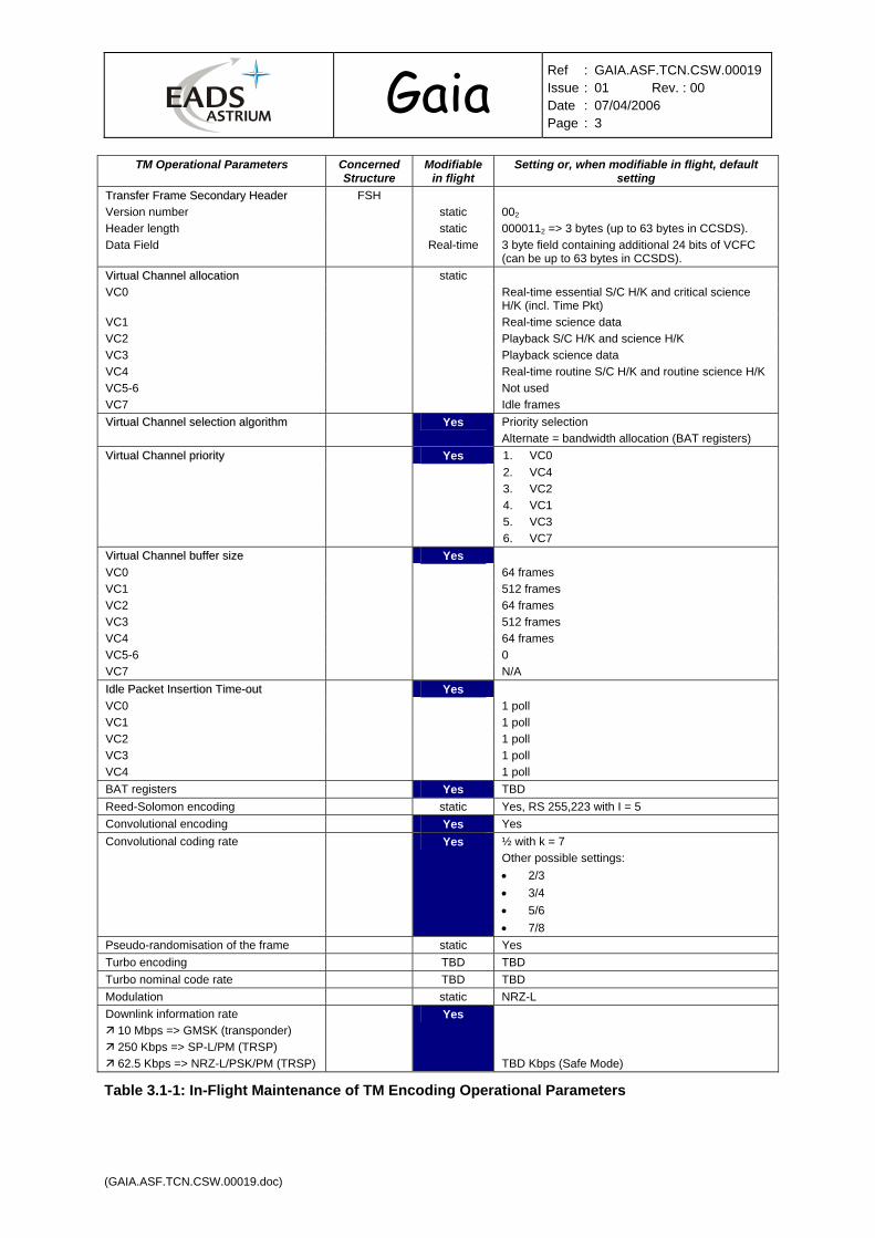
All TM encoding parameters in Table 3.1-1: In-Flight Maintenance of TM Encoding Operational Parameters that are specified as “modifiable in flight” shall be stored into non-volatile, rewritable, memories.
TM Operational Parameters Concerned Structure
Modifiable in flight
Setting or, when modifiable in flight, default setting
Attached Synchronisation Marker CADU No, static 1ACF_FC1D16
Frame Length before encoding TF static 1,115 bytes (i.e., 8920 bits) TC Decoder (TCD) selection for CLCW retrieval
Oper Control Field (OCF)
static CLCW from nominal decoder in TF with even Master Channel Frame count; redundant => odd.
Frame Error Control (FEC) TF Trailer static Yes Time strobe static Yes Time strobe rate Yes Once per 64 VC0 frames
Other possible settings: • 16 frames • 32 frames • 128 frames • 256 frames
TTrraannssffeerr FFrraammee PPrriimmaarryy HHeeaaddeerr:: FPH Version number static 002
Spacecraft ID SCID static TBD by ESA Virtual Channel ID VCID Real-time See VC allocation below Operational Control Field OCF static Yes = 12
Master Channel Frame Count MCFC Real-time Virtual Channel Frame Count VCFC Real-time See also “Data Field” in secondary header below. Transfer Frame Data Field Status
Transfer Frame 2’ry Header Flag static Yes = 12
Data Field Synchronisation Flag static Octet-synch’d and forward-ordered = 02
Packet Order Flag static Forward packet count order = 02
Segment Length Identifier static 112, for VC0, VC1, VC2, VC3, and VC4 First Header Pointer Real-time
Gaia Ref : GAIA.ASF.TCN.CSW.00019
Issue : 01 Rev. : 00 Date : 07/04/2006 Page : 3
(GAIA.ASF.TCN.CSW.00019.doc)
TM Operational Parameters Concerned Structure
Modifiable in flight
Setting or, when modifiable in flight, default setting
TTrraannssffeerr FFrraammee SSeeccoonnddaarryy HHeeaaddeerr FSH Version number static 002
Header length static 0000112 => 3 bytes (up to 63 bytes in CCSDS). Data Field Real-time 3 byte field containing additional 24 bits of VCFC
(can be up to 63 bytes in CCSDS). VViirrttuuaall CChhaannnneell aallllooccaattiioonn static VC0 Real-time essential S/C H/K and critical science
H/K (incl. Time Pkt) VC1 Real-time science data VC2 Playback S/C H/K and science H/K VC3 Playback science data VC4 Real-time routine S/C H/K and routine science H/K VC5-6 Not used VC7 Idle frames VViirrttuuaall CChhaannnneell sseelleeccttiioonn aallggoorriitthhmm Yes Priority selection
Alternate = bandwidth allocation (BAT registers) VViirrttuuaall CChhaannnneell pprriioorriittyy Yes 1. VC0 2. VC4 3. VC2 4. VC1 5. VC3 6. VC7 VViirrttuuaall CChhaannnneell bbuuffffeerr ssiizzee Yes VC0 64 frames VC1 512 frames VC2 64 frames VC3 512 frames VC4 64 frames VC5-6 0 VC7 N/A IIddllee PPaacckkeett IInnsseerrttiioonn TTiimmee--oouutt Yes VC0 1 poll VC1 1 poll VC2 1 poll VC3 1 poll VC4 1 poll BAT registers Yes TBD Reed-Solomon encoding static Yes, RS 255,223 with I = 5 Convolutional encoding Yes Yes Convolutional coding rate Yes ½ with k = 7
Other possible settings: • 2/3 • 3/4 • 5/6 • 7/8
Pseudo-randomisation of the frame static Yes Turbo encoding TBD TBD Turbo nominal code rate TBD TBD Modulation static NRZ-L Downlink information rate
10 Mbps => GMSK (transponder) 250 Kbps => SP-L/PM (TRSP) 62.5 Kbps => NRZ-L/PSK/PM (TRSP)
Yes TBD Kbps (Safe Mode)
Table 3.1-1: In-Flight Maintenance of TM Encoding Operational Parameters

Gaia Ref : GAIA.ASF.TCN.CSW.00019
Issue : 01 Rev. : 00 Date : 07/04/2006 Page : 4
(GAIA.ASF.TCN.CSW.00019.doc)
3.1.2 Telecommand
The TC decoder operates from mission-critical parameters (e.g., spacecraft identifier) that are stored into non-volatile memory.
All TC decoding parameters in Table 3.1-2: In-Flight Maintenance of TC Decoding Operational Parameters that are specified as “modifiable in flight” shall be stored into non-volatile, rewritable, memories.
TC Operational Parameters Concerned Structure
Modifiable in flight
Setting or, when modifiable in flight, default setting
CCooddiinngg LLaayyeerr ((CCLLTTUU)) TC channel selection mode No, static
(note 1) Priority selection (note 1) Alternate modes would be (selectable during manufacturing): • Standard selection • Dynamic selection
PPsseeuuddoo--ddeerraannddoommiisseerr static TBD by ESA TTrraannssffeerr LLaayyeerr ((TTCC TTrraannssffeerr FFrraammee)) TTCC FFrraammee PPrriimmaarryy HHeeaaddeerr Version number Bypass flag Control command flag Reserved field Spacecraft ID Virtual Channel decoder A Virtual Channel decoder B
SCID VCID
static
Real-time Real-time
static static static
002
Bypass Flag Ctl Cmd Flag Meaning 0 0 AD frame: seq-ctrld data 0 1 Illegal 1 0 BD frame: expedited data 1 1 BC frame: FARM-1
002
TBD by ESA 0000002
0000012
FARM positive window static 6416
FARM negative window static 6416
AAuutthheennttiiccaattiioonn LLaayyeerr Authentication key Not used TBC by ESA Authenticated MAP ID pointer No 0 => no MAP authenticated SSeeggmmeennttaattiioonn LLaayyeerr MAP-ID static MAP 0 = CPDU
MAP 1 = currently active processor, A or B. (MAP not used to make distinction between A & B). MAP 4 = “Abort_ongoing_CPDU_packet_execution” MAP 5 = “Reset TM/TC” MAP 6 = “TC Only Mode”
CPDU enable/disable static Enabled CPDU packet version number static 0 (TBC) CPDU packet type field static 1 (TBC) CPDU packet data field header flag static 0 (TBC) CPDU application ID static TBD MAP 1 transfer frequency No [250..600] Kbps CPDU MAP ID No 0 CPDU PM lockout No 16 (TBC) CPDU indiv. parity No No CSEL link time-out No 16 s (TBC) CPDU duration parameter No 13 ms (TBC) CPDU delay between pulses No 5.9 ms (TBC) TC Only time-out No 16 s (TBC)
Table 3.1-2: In-Flight Maintenance of TC Decoding Operational Parameters


Gaia Ref : GAIA.ASF.TCN.CSW.00019
Issue : 01 Rev. : 00 Date : 07/04/2006 Page : 6
(GAIA.ASF.TCN.CSW.00019.doc)
3.2 REQUIREMENTS RELATED TO CDMU RECONFIGURATION PARAMETERS
The Gaia Control and Data Management Unit (CDMU) implements all the basic alarm conditioning and reconfiguration mechanisms necessary for recovering from failures havind led to any of these alarms:
• CDMU’s internal alarms: Under-Voltage Dectection (UVD), processor watchdog, memory surveillance, etc.
• External system alarms: power alarm detection, separation straps.
• SW-triggered alarms: SW-implemented FDIR suspends generating the software alive signal destined for the Reconfiguration Module watch-dog.
ProcessorModule(PM)
SVMUnits
PLMUnits
CentralSoftware(CSW)
HighPriority
TM
ReconfigurationModule(RM)
TC / TM
CDMUInternalAlarms
TCDecoder
PLMMIL-bus
EIU
Systemalarms
SW-triggeredAlarms
TM
TC
TM
CPDU
HPC-1
HPC-2
HPC-3
SVMMIL-bus
SpW
Systemstatus
The CDMU reconfiguration operates from mission-critical parameters (e.g., alarm patterns) that are stored into non-volatile memory.
All CDMU reconfiguration parameters in Table 3.2-1: In-Flight Maintenance of CDMU Reconfiguration Operational Parameters that are specified as “modifiable in flight” shall be stored into non-volatile, rewritable, memories.
The definition below is preliminary and will be updated after the selection of CDMU contractor.
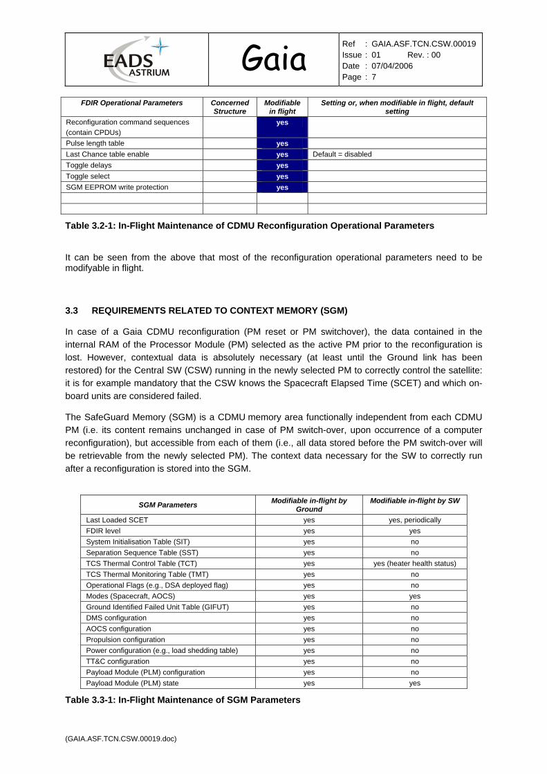
FDIR Operational Parameters Concerned Structure
Modifiable in flight
Setting or, when modifiable in flight, default setting
Alarm polarity No, static Active low or active high Alarm temporisation yes Initial setting depends upon alarm Alarm enable (for each enable) yes Initial setting depends upon alarm Alarm voting enable static Programmable alarm pattern table yes Alarm mask yes
Gaia Ref : GAIA.ASF.TCN.CSW.00019
Issue : 01 Rev. : 00 Date : 07/04/2006 Page : 7
(GAIA.ASF.TCN.CSW.00019.doc)
FDIR Operational Parameters Concerned Structure
Modifiable in flight
Setting or, when modifiable in flight, default setting
Reconfiguration command sequences (contain CPDUs)
yes
Pulse length table yes Last Chance table enable yes Default = disabled Toggle delays yes Toggle select yes SGM EEPROM write protection yes
Table 3.2-1: In-Flight Maintenance of CDMU Reconfiguration Operational Parameters
It can be seen from the above that most of the reconfiguration operational parameters need to be modifyable in flight.
3.3 REQUIREMENTS RELATED TO CONTEXT MEMORY (SGM)
In case of a Gaia CDMU reconfiguration (PM reset or PM switchover), the data contained in the internal RAM of the Processor Module (PM) selected as the active PM prior to the reconfiguration is lost. However, contextual data is absolutely necessary (at least until the Ground link has been restored) for the Central SW (CSW) running in the newly selected PM to correctly control the satellite: it is for example mandatory that the CSW knows the Spacecraft Elapsed Time (SCET) and which on-board units are considered failed.
The SafeGuard Memory (SGM) is a CDMU memory area functionally independent from each CDMU
PM (i.e. its content remains unchanged in case of PM switch-over, upon occurrence of a computer reconfiguration), but accessible from each of them (i.e., all data stored before the PM switch-over will be retrievable from the newly selected PM). The context data necessary for the SW to correctly run after a reconfiguration is stored into the SGM.
SGM Parameters Modifiable in-flight by Ground
Modifiable in-flight by SW
Last Loaded SCET yes yes, periodically FDIR level yes yes System Initialisation Table (SIT) yes no Separation Sequence Table (SST) yes no TCS Thermal Control Table (TCT) yes yes (heater health status) TCS Thermal Monitoring Table (TMT) yes no Operational Flags (e.g., DSA deployed flag) yes no Modes (Spacecraft, AOCS) yes yes Ground Identified Failed Unit Table (GIFUT) yes no DMS configuration yes no AOCS configuration yes no Propulsion configuration yes no Power configuration (e.g., load shedding table) yes no TT&C configuration yes no Payload Module (PLM) configuration yes no Payload Module (PLM) state yes yes
Table 3.3-1: In-Flight Maintenance of SGM Parameters

Gaia Ref : GAIA.ASF.TCN.CSW.00019
Issue : 01 Rev. : 00 Date : 07/04/2006 Page : 8
(GAIA.ASF.TCN.CSW.00019.doc)
3.4 REQUIREMENTS RELATED TO SOFTWARE MAINTENANCE
3.4.1 Case of Central Software (CSW)
The ESA MRD requires that two Central Software (SW) images are stored into CDMU non-volatile memory.
A Central Software (CSW) upgrade capability will have to be implemented on board Gaia CDMU: a “flip-flop” strategy bringing a robust Central Software (CSW) upgrade into EEPROM is shown on Figure 3.4-1: Software Upgrade Capability into EEPROM below.
CURRENT ReferenceCOMPLETE SW Release
ALTERNATECOMPLETE SW Release
Nominal Computer 3Mb EEPROM
CURRENT ReferenceSET of Patches
ALTERNATESET of Patches
Safeguard EEPROM
Computer-Nom Firmware information
Computer-Red Firmware information
0x20 0000
0x10 0000
0x00 0000
0x28 0000
CURRENT ReferenceCOMPLETE SW Release
ALTERNATECOMPLETE SW Release
CURRENT ReferenceSET of Patches
ALTERNATESET of Patches
0x20 0000
0x10 0000
0x00 0000
0x28 0000
Redundant Computer 3 Mb EEPROM
Boot load in RAM(Complete SW thenoptionally Patches)
NominalComputer
RAM
Figure 3.4-1: Software Upgrade Capability into EEPROM
This scheme ensures command/control service continuity throughout the in-flight software maintenance. Nonetheless, it relies on the fact that the transponder provides (i) a protection of its configuration parameters, and (ii) a duly flight-qualified software (if any).
This scheme also ensures that 2 safe images still exist in case of failure during SW maintenance.
3.4.2 PLM Processors
The reconfiguration of the PLM processors is under the authority of the Central Software (CSW) running in the CDMU, or performed through On-Board Control Procedures (OBCPs). So, the maintenance of a PDHU processor or the maintenance of one VPU is executed from a safe external source: the CSW.
Therefore, though a certain level of service continuity might be required when maintaining the PDHU processor software image or maintaining one VPU software image, this does not call for preserving two safe images in case of failure during software maintenance because PDHU and VPU are not safety-critical items for the survival of the spacecraft as the CDMU is: so, no duplication of software images is required for each PDHU processor and for one VPU processor.

Gaia Ref : GAIA.ASF.TCN.CSW.00019
Issue : 01 Rev. : 00 Date : 07/04/2006 Page : 9
(GAIA.ASF.TCN.CSW.00019.doc)
4 UNDERSTANDING THE EEPROM “WEAK CELL” PROBLEM
4.1 INTRODUCTION
A Hitachi 1-Mbit EEPROM die - HCN58C1001 - is packaged by vendors (Maxwell, Austin) into various space-qualified EEPROM packages and used in many US and EU space projects. The Pléiades, Aeolus and Herschel-Planck CDMU use the Maxwell Technologies 4 Mbit EEPROM (reference: 79C0408, 40-pin Flat-Pack). Maxwell 4 Mbit EEPROM are MCMs organized as 512K x 8. The devices use four of the Hitachi 58HC1001 1 Mbit EEPROM die.
Several EEPROM failures were reported by space missions, irrespective of the vendor source (Maxwell or Austin). On 25 August 2005, the NASA advisory NA-GSFC-2005-04 formally reported failures centred on systems based on the Hitachi die: “weak cells” are pointed out as the intermediate cause of failure, thus shortening the data retention lifetime. See [gsfc_adv]. Failures occurred on ground and in flight, in BB, EM and FM. They range from single bit programmed with “0” (charged state) and read back as a “1” (discharged state) to 128-byte page corruption. The invoked intermediate cause of the failures is a weakness of the data retention caused by cell discharge, which has been called “weak cell”. An AETD/NASA slide presented on 12-Oct-2005 – see hereafter – shows various voltage profiles.

Gaia Ref : GAIA.ASF.TCN.CSW.00019
Issue : 01 Rev. : 00 Date : 07/04/2006 Page : 10
(GAIA.ASF.TCN.CSW.00019.doc)
October 12, 2005 AETD EEPROM Advisory Briefing 6
Sample FailuresSample Failures
Single Read Bit Oscillation
Multiple Read Bit Oscillation
Single Bit Cell Discharge
Thhee rroooott ffaaiilluurree mmeecchhaanniissmm lleeaaddiinngg ttoo ““wweeaakk cceellllss”” rreemmaaiinnss uunnkknnoowwnn.
4.2 RELIABILITY DATA
Data retention is a measure of the time a non-volatile memory can retain programmed data.
JPL Investigation A publication based on experimental data – see [jpl_investig] - shows that an intrinsic1 EEPROM data retention failure should not be expected within the first 6 years of operation under operating condition of 50°C to 60°C, which was the temperature of the mission observing the failures in flight.
When addressing extrinsic bit failure, so considering process-induced or poor programming, the data retention rating of weak cells may decrease dramatically. This is not predictable.
Also, weak cells are more susceptible to high temperature operation than nominal cells.
Finally, nominal cells can become weak cells if the memory chip is not operated properly, i.e., not in accordance with the EEPROM manufacturer data sheet.
1 Taking into account EEPROM reliability data from the manufacturer, notwithstanding external factors such as programming by end-user(s) or digital circuit design.

Gaia Ref : GAIA.ASF.TCN.CSW.00019
Issue : 01 Rev. : 00 Date : 07/04/2006 Page : 11
(GAIA.ASF.TCN.CSW.00019.doc)
Conclusion: so far, failures due to weak cells could not been mathematically modelled as intrinsic bit failures are. As experimentally demonstrated by JPL, their rate can be several orders of magnitude higher than statistical failure data (conventional fits we manipulate) if extrinsic factors are not dealt with properly (process, programming, circuit design).
Maxwell Data Maxwell relates that impurities in the material might be sufficient to cause cells to leak off in days or weeks rather than years. Ionizing radiations (TID) may also create paths for leakage. Standard testing and screening methods do not always find these infant mortalities. Therefore, Maxwell developed specific tests to evaluate the Hitachi HN58C1001 EEPROM for data retention both before irradiation and after irradiation up to 40 krad (Si).
Maxwell – see [maxwell_ws] - issued the following testing facts on 12-Oct-2005:
Ultracapacitors Microelectronics High-Voltage Capacitors
Reliability
• Life Test – Maxwell has life tested over 750 devices, since 1996, and have had 0 failures.
• Data Retention Screening - Since February 2003 Maxwell has tested over 8000 device and has had only four failures. No devices havebeen returned to Maxwell with data retention issues that have received data retention testing.
• Endurance Testing – Since 1996 Maxwell has endurance tested over 100 EEPROM devices to greater than 10,000 Erase/Write cycles with 0 failures.
• Radiation Testing – Every EEPROM die lot is TID tested to ensure the devices meet specification. SEL testing shows no latch-up at 125°C to > 85 Mev/mg/cm2.
Maxwell’s plan for minimising the risk of delivering weak devices covers:
• Data retention screening as part of production testing. The test relies on accelerating the leakage characteristics – thus unveiling weak cells – in bringing the device during 72 hours at 150°C where it is typically used at much lower operational temperatures (~55°C). All flight lots undergo such testing. The EEPROM devices are programmed with a specific test pattern (55AA) and software data protection is enabled (unintentional writes to the EEPROM due to noise on the control bus or bus contentions are avoided). At the end of the test, the pattern is checked and failed devices are counted (and removed from delivered lots). The principle of temperature acceleration is used when determining component reliability. The Arrhenius model (equation 1) predicts failure based on time acceleration due to temperature.
AF = e E/k * [1/T1 – 1/T
2] (1)

Gaia Ref : GAIA.ASF.TCN.CSW.00019
Issue : 01 Rev. : 00 Date : 07/04/2006 Page : 12
(GAIA.ASF.TCN.CSW.00019.doc)
Where AF = acceleration factor E = activation energy; here Hitachi supplies 1.1 eV. K = Boltzmann constant = 8.6 * 10-5 eV/K T1 = lower temperature T2 = higher temperature From this equation, the data retention test performed by Maxwell simulates a 50 year period.
• Data retention with radiation: Maxwell reports in [maxwell_rel] that no data retention failures occurred on parts irradiated beforehand. This shows that leakage generated by total ionising dose of 40 krad(Si) do not have a noticeable influence on data retention.
• Endurance testing: The HN58C1001 EEPROM is specified for 10,000 erase/writes cycles.
Maxwell performed an endurance test on 10 pieces combining 20,000 erase/writes cycles, data retention tests and 40 krad(Si) irradiation: all devices passed the tests. Endurance and data retention are not affected by TID at 40krad(Si).
Austin Data As highlighted in [austin_adv], Austin Semiconductor reports that reprogramming a device showing an output oscillation cures the problem: reprogrammed bits or pages recover. This is not understood, it is just a fact. Austin works on isolating the root cause of the oscillation.
Like Maxwell did, Austin has implemented special weak cell screening methods in their test program.
Austin put some focus on the interest of screening of weak cells on board or unit level through specific tests:
• Adjusting the Vcc to higher than the 5.5 V max spec setting at cold temperature, and lower than 4.5 V min spec setting at high temperature. Austin recommends 6.0 V as max Vcc setting for infant mortality and burn-in screening operations.
• Read-only loop test to unveil oscillating data bit. Effect of temperature Weak cells are more susceptible to high temperature operation than nominal cells. The data retention guaranteed by Hitachi at 55°C is 10 years (not 50 years as a result of screening performed by Maxwell as described above).
Considering a 30°C thermal reference point (as typically used for reliability computations of space equipment units) the maximum PCB temperature considering a typical box and PCB thermal design is about 60°C. Using equation 1, this would reduce the data retention lifetime from 10 years down to 5.5 years with an activation energy of 1.1 eV/K, which is below the 6.5-year extended lifetime of Gaia.
Therefore, for Gaia, the upper limit of the EEPROM operational temperature will have to be specified as lower or equal than 55°C. In other words, the manufacturer specification will be strictly respected. Thermal analyses and qualification tests will have to demonstrate compliance to this requirement.
Programming “Weak cells” can be induced by programming outside the specification of the manufacturer.
Maxwell and Austin used to delivering their devices to the users (unit manufacturers) in the erased state, i.e., with a logic level “1”.
Now, Maxwell deliver the EEPROM with all “0” and software data protection is disabled allowing users to program the devices with programmers that support the Hitachi HCN58C1001 EEPROM

Gaia Ref : GAIA.ASF.TCN.CSW.00019
Issue : 01 Rev. : 00 Date : 07/04/2006 Page : 13
(GAIA.ASF.TCN.CSW.00019.doc)
programming algorithm. They recommend a check that all cells still show “0” as part of the incoming inspection.
This allows covering the period of time from final testing at manufacturer’s site till incoming inspection, covering storage, shipment, transport. However, it is not proven that this brings a high value in terms of infant mortality screening: the data retention life test is much more valuable.
Circuit design NASA reports that problems traced to marginal circuit design timing were eliminated by design modifications.
As stated in Saab Ericsson Space [EEPROM_exp], EEPROM is known to be sensitive to noise on its control signals (e.g., the write strobe signal). Noise may trigger the internal state machine and the write cycle might be initiated with wrong contents. This is true even if the EEPROM is locked through the software data protection algorithm provided by the manufacturer/vendor.
It is essential to respect the data sheet timing requirement (e.g., 10 ms delay when writing to the EEPROM and crossing a page boundary). The circuit design around the EEPROM must protect the EEPROM against SW performing writes to the device without respecting the data sheet timing requirement.
The unit manufacturer will be requested to inform the SW designers or the operators of the constraints they must respect when utilising the EEPROM directly.
The circuit design must allow the EEPROM Vcc to reach the rated level before initiating any reads or writes to the device. No power should be removed while a write cycle is in process.
Synthesis From the above discussion, the following synthesis can be made:
• Intrinsically (device ratings as specified by manufacturer/vendor): - During production and initial programming phases at die manufacturer or device
vendor, data retention failures can be eliminated through data retention screening. - Flight lots are 100% screened to 50-year lifetime of data retention such that no parts
are expected to fail. But specification guarantees a data retention time of 10 years at 55°C.
- Data retention is not affected by irradiation @ 40 krad(Si). - Endurance of 10,000 erase/write cycles is guaranteed at 40 krad(Si).
• Extrinsically (use of device by Gaia unit manufacturer and system/operations): - Though Hitachi 1 Mbit EEPROM is conservatively specified by manufacturer/vendor,
strict adherence to manufacturer/vendor data retention time, temperature regression and erase/write endurance is recommended.
- Programming: use programmers certified as implementing Hitachi HCN58C1001 EEPROM programming algorithm. Use page mode programming method.
- Circuit design: respect data sheet requirements and protect against SW attempting to violate
timing requirements. Avoid floating signals.
- Utilisation: respect data sheet requirements of less than 10,000 writes in page mode.
Keep track of erase/write cycles. EEPROM operational temperature after installation within box and spacecraft
to remain below or equal to 55°C.

Gaia Ref : GAIA.ASF.TCN.CSW.00019
Issue : 01 Rev. : 00 Date : 07/04/2006 Page : 14
(GAIA.ASF.TCN.CSW.00019.doc)
5 ANALYSIS OF EEPROM IMPLEMENTATION FOR GAIA
5.1 GAIA VS. GENERAL DISPOSITIONS ADOPTED BY EADS EEE COMMITTEE
This section provides the list of general dispositions made by the EADS EEE committee and gives the position of Gaia against these company rules. Whenever they are made applicable to Gaia, they will be explicitely formulated hereafter in §5.2 such as to gather all Gaia requirements into a unique section.
• R1 : Verify that the EEPROM is the better choice for the application or could be changed by an other solution (PROM, Flash).
Analysis performed for Gaia in §3 above: use of EEPROM is mandatory for Gaia.
Starting from that fact, the strategy for Gaia is focused on implementing the mechanisms to detect an EEPROM bit or page failure such as to allow for recovery of safe data/code from alternate memory sources. All software components and/or parameters that remain constant throughput the mission will be stored in PROM.
If EEPROM is the better choice :
• R2 : Verify that the specification is met in all conditions (brown-outs, unintentional power-
down, unexpected resets) - R2-1 : Verify that command signals are clean on power-up / power down. - R2-2 : Verify the programming timings, especially Chip Enable (CE) and Write Enable
(WE) must keep stable during 50µs after the low level Vcc.
These two recommendations will be taken into account for the design of any PLM and SVM units that contain EEPROM. The unit design will be required to consider circuit operation if the power is shut down during a write cycle, either planned or unexpected. This can be limited to the completion of single page write in progress, it does not call for completing a “massive” EEPROM programming such as a software image programming.
- R2-3 : Verify that the number of write cycles is lower than the specification limit, even in
case of repetitive writes (functional tests or software loop)
This recommendation will be taken into account for the design of the software having access to the EEPROM in writing. In particular, dedicated tests will be performed to trace the EEPROM write profiles and ensure that no SW misbehaviour exists. Wherever it is anticipated that the number of writes may exceed the manufacturer ratings @ EEPROM operational temperature, the possibility to define a set of memory pages as consumables (data written into one page, then written into a new page when the previous page has exhausted, and so on) will be analysed. The writes will be performed on a page basis, not on a byte basis, because there is a ratio of 10 between the two modes in terms of number of erase/write cycles.
• R3 : Minimize crosstalk and signal / Vdd noise, especially no glitch longer than 5ns must be
detected on command signals.

Gaia Ref : GAIA.ASF.TCN.CSW.00019
Issue : 01 Rev. : 00 Date : 07/04/2006 Page : 15
(GAIA.ASF.TCN.CSW.00019.doc)
These two recommendations will be taken into account for the design of any PLM and SVM units that contain EEPROM. Note that the Hitachi EEPROM device features 20 ns noise filters on CE, WE and OE control pins.
• R4 : Prefer page write instead byte writes.
These two recommendations will be taken into account for structuring and accessing
EEPROM functional groups of data (e.g., SGM groups, RM groups, etc.).
• R5 : Keep the temperature as low as possible, especially during redundancy test. Decrease the operation temperature in case of long mission.
The EEPROM will be located into PCB areas that excludes heat spot. As already
stated above, the max EEPROM operational ambient temperature shall be maintained below 55°C to preserve the 10-year data retention time.
• R6 : Specify to the EEPROM manufacturer that the parts have to be delivered with all bits in
the erased state, i.e., written with “0”. Verify the “0” level in incoming inspection.
This recommendation will be applied. The requirement has already been complied with by Maxwell. For Austin, it is sufficient to state the requirement within the EEE procurement specification. In accordance with [austin_adv], Austin will accept the requirement. The requirement for incoming screening will have to be clear in unit manufacturer Statement of Work (SoW).
• R7 : Do not use EEPROM for critical applications.
Not possible. The Gaia Central Software (CSW) and critical parameters (TM,
reconfiguration, SGM) are modifiable in flight.
If the EEPROM use cannot be avoided for critical applications : • R8 : Implement an EDAC protection • R9 : Perform a periodic checksum • R10 : Have a code redundancy in an other EEPROM
These recommendations will be made applicable to Gaia with the following precisions
or amendments: • R8: As advised in [AETD_appli], the use of EDAC can not be relied upon to
totally compensate for single “weak bits”. Indeed, in case of an oscillating bit failure, there is no guarantee that the EDAC itself will operate correctly with voltage transitions applied to its inputs. This is the reason why it is recommended to apply the EDAC requirement while allowing possible off-the-shelf designs w/o such feature to be selected with other protection means such as data group checksum with checksum computed by software.
• R9: checksum computation should not be necessarily seen as a kind of memory scrubbing as it is done for RAM. For the EEPROM containing a SW image and the SGM that would be used in case of a spacecraft Safe Mode, it is instead recommended to have periodic dumps and checksum computations performed from the ground. Of course, during a CDMU (re-)initialisation, a check is performed when attempting loading from EEPROM into RAM.
Gaia Ref : GAIA.ASF.TCN.CSW.00019
Issue : 01 Rev. : 00 Date : 07/04/2006 Page : 16
(GAIA.ASF.TCN.CSW.00019.doc)
• Having redundancy in another EEPROM is safe if and only if the probability of weak cells is low in comparison with the failure rate of the EEPROM. This is the reason why it is recommended to rather envisage alternate loading from a SSMM (for critical equipment only).

Gaia Ref : GAIA.ASF.TCN.CSW.00019
Issue : 01 Rev. : 00 Date : 07/04/2006 Page : 17
(GAIA.ASF.TCN.CSW.00019.doc)
5.2 EEPROM PROTECTION REQUIREMENTS FOR GAIA
At the light of Gaia mission requirements expressed in §3 and understanding of EEPROM weak cell issue, the following set of requirements has been derived for application to Gaia on:
• Component level.
• Circuit design level (electronic board, unit).
• System level (including software and firmware of critical items).
• Operations level.
Before going into the details, let us give the definitions of safety criticality and mission criticality for the sake of clarity of the requirements expressed hereafter. It is important to consider the criticality classification herein made as relevant to the EEPROM issue resolution. One should not extrapolate this classification to other engineering or quality assurance subjects without analysis beforehand.
• Safety critical: an item is herein classified as safety critical whenever a failure of it would cause loss of the spacecraft. Here, all the Gaia items involved in the execution of the spacecraft Safe Mode (safe attitude, protection of the instrument from Sun, Earth TM/TC) will be considered as safety critical.
• Mission critical: an item is herein classified as mission critical whenever a failure of it would cause severe degradation of the Gaia PLM scientific mission.
TRSP PAA CDMU CSW EIU GYRO STR PDHU VPU
PEM IM CDU
Safety critical software
(for Safe
Mode) (Boot code)
(Safe Mode) (if
any)
Mission critical software
(TBC)
Anticipated in flight SW code
change
(TBC)
Safety critical parameters
Mission critical parameters
Anticipated in-flight
configuration parameter
change
(Look-Up
Tables)
(TM, TC)
(REC)
(SGM) (Star
catalog)
Convention on requirements numbering: aaa-EEPROM-bbb-number
aaa
GEN requirements apply to any GAIA unit featuring EEPROM devices inside.
COM requirements apply to computerised unit with SW: transponder, CDMU, STR, PDHU, VPU.
XXX requirements apply to XXX item in the Gaia architecture.
bbb EEE (for component level),
EQT (for board/unit design and ground operations),
SYS (for system design and ground operations),

Gaia Ref : GAIA.ASF.TCN.CSW.00019
Issue : 01 Rev. : 00 Date : 07/04/2006 Page : 18
(GAIA.ASF.TCN.CSW.00019.doc)
OPS (for operations)
Gaia Ref : GAIA.ASF.TCN.CSW.00019
Issue : 01 Rev. : 00 Date : 07/04/2006 Page : 19
(GAIA.ASF.TCN.CSW.00019.doc)
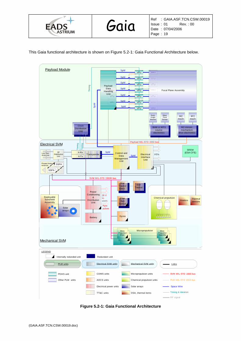
This Gaia functional architecture is shown on Figure 5.2-1: Gaia Functional Architecture below.
CDU
Solar arrays
DeployableSunshieldAssembly
Chemical propulsion
STRE STR
Low GainAntennas
Phased ArrayAntenna
TRSPX-Rx
X-TxTransponder
SSPA
SSPA
SSPA
StarTrackerElect.
StarTracker
STRE
FineSun
Sensor
Gyros
PowerConditioning
&Distribution
Unit
Battery
Heaters Thermalsensors
VPU
VPU
VPU
VPU
VPU
VPU
VPU
VPU
VPU
VPU
PayloadData
HandlingUnit
28 Vtousers
VPU
VPU
VPU
VPU
VPU
VPU
VPU
Focal Plane Assembly
Payload Module
Electrical SVM
Mechanical SVM
Micropropulsion
ClockDistribution
Unit
SpW
SpW
SpW
SpW
SpW
SpW
SpW
SpW
SpW
SpW
Tim
ing
Tim
ing
Tim
ing
SVM MIL-STD 1553B bus
Payload MIL-STD 1553 bus
PLM units
PDHS unit
Other PLM units
Electrical SVM units
CDMS units
AOCS units
Electrical power units
TT&C units
Mechanical SVM units
Micropropulsion units
Chemical propulsion units
Solar arrays
DSA, thermal items
Links
Timing & datation
PLM MIL-STD 1553 bus
Space Wire
SVM MIL-STD 1553 bus
Pyropulses
LEGEND
Control andData
ManagementUnit
TransponderX-Rx
X-Tx
RF signal
STRESTRE
MicroPropulsion
Elect.
I/O’s
Internally redunded unit
STRESTRE
MicroPropuslionAssembly
BAM & WFSsource
electronics
M2 mirrorsmechanism
drive electronics
Redundant unit
BasicAngleMonitor
WaveFront
Sensor
M2mech
M’2mech
BAM & WFSsource
electronics
M2 mirrorsmechanism
drive electronics
SREM(ESA-CFE)SpWRF
DistributionUnit
ElectricalInterface
Unit
Figure 5.2-1: Gaia Functional Architecture
Gaia Ref : GAIA.ASF.TCN.CSW.00019
Issue : 01 Rev. : 00 Date : 07/04/2006 Page : 20
(GAIA.ASF.TCN.CSW.00019.doc)
5.2.1 Component Level Requirements
These requirements apply to the EEPROM procurement specifications. Unit manufacturers shall take these requirements into account as self-procurement is the procurement baseline for Gaia.
Source: [gsfc_adv]
GEN-EEPROM-EEE-10:The procurement specifications of all EEPROM lots shall have a clause that requires the manufacturer to perform, as part of the screening flow :
• functional tests of each memory cell at 3 temperatures and 3 voltages, at max speed • data retention tests
Source: [maxwell_rel]
GEN-EEPROM-EEE-20: The procurement specifications shall require from the manufacturer proof that the data retention is 10 years at 55°C and remains unaffected by TID @ 40 krad(Si) and endurance of 10,000 erase/write cycles on a page programming basis.
Source: : [gsfc_adv]
GEN-EEPROM-EEE-30: The procurement specifications shall require that the EEPROM devices are shipped with all bits programmed to the logical state “0” (charged state) and software data protection disabled such as to allow the users to program the devices for their applications.
5.2.2 Equipment Level Requirements
These requirements apply to the Gaia SVM and PLM electronic board/unit circuit design and ground operations.
Incoming inspection
Source: EADS EEE (R6)
GEN-EEPROM-EQT-10: As part of their EEE incoming inspections, the unit manufacturers shall perform a data retention screening in order to check that all cells are still in the logical state “0” (charged state). Possible faulty devices shall be discarded and an alert raised.
EEPROM programming
Source: Created
GEN-EEPROM-EQT-20: Programming of individual devices in board or unit production shall be done with certified programmers that support the device manufacturer/vendor programming algorithms.
Source: Created
GEN-EEPROM-EQT-30: When programming can be performed afer box sealing through a test interface or a functional interface, the board or unit manufacturer shall provide the procedure to be

Gaia Ref : GAIA.ASF.TCN.CSW.00019
Issue : 01 Rev. : 00 Date : 07/04/2006 Page : 21
(GAIA.ASF.TCN.CSW.00019.doc)
used by end-users for a safe programming of the EEPROM area, specifying in particular the timing constraints and possible checkpatterns to be written into unused memory locations.
Source: Created
GEN-EEPROM-EQT-40: Precautions to be implemented during flight operations for minimising the risk of EEPROM susceptibility to radiations during writes shall be documented by the board or unit manufacturer.
Source: EADS EEE (R4) as amended
GEN-EEPROM-EQT-50: Page writes shall be used for programming EEPROM. Unused bytes shall contain the checkpatterns.
Source: [gsfc_adv]
GEN-EEPROM-EQT-60: Wherever the capability to erase/write EEPROM is provided, a software write protection feature shall be implemented and accessible to the ground through TC.
Circuit Design
Source: EADS EEE (R2-1, R2-2)
GEN-EEPROM-EQT-70: The design of units incorporating EEPROM shall strictly conform to the EEPROM manufacturer/vendor data sheet timing requirements.
Source: EADS EEE (R2-1, R2-2)
GEN-EEPROM-EQT-80: The EEPROM control signals shall remain within timing specifications in case of power shut down during a write cycle.
Source: EADS EEE (R3)
GEN-EEPROM-EQT-90: The design of units incorporating EEPROM shall be such that no glitch longer than 5 ns are detected on EEPROM control signals.
Source: [gsfc_adv]
GEN-EEPROM-EQT-100: The EEPROM read access time shall be increased as much as possible (as an opportunity to mitigate the “weak cell” effect, except for the case when the voltage oscillates).
Tracking of number of erase/write cycles
Source: EADS EEE (R2-3)
GEN-EEPROM-EQT-110: The board or unit manufacturer shall keep trace of the number of erase/write cycles performed prior to the delivery of the board/unit.
Thermal
Source: EADS EEE (R5) made precise

Gaia Ref : GAIA.ASF.TCN.CSW.00019
Issue : 01 Rev. : 00 Date : 07/04/2006 Page : 22
(GAIA.ASF.TCN.CSW.00019.doc)
GEN-EEPROM-EQT-130: The board/unit design shall be such that the case temperature of the EEPROM devices is kept below 55°C.
5.2.3 System Level Requirements
These requirements are derived from the Gaia system design and operations. They apply to the SVM and PLM units as well as to the Central Software (CSW) and embedded software (e.g., embedded in CDMU, PDHU, VPU, STR, transponder).
Refer to the criticality definitions and classification set forth at the beginning of §5.2 hereabove.
EEPROM code and data protection
Source: ESA MRD SENV-300 and [gsfc_adv] as amended
GEN-EEPROM-SYS-10: The use of Error Detection and Correction (EDAC) is recommended, but cannot be relied upon totally to compensate for “weak cells” manifestation such as oscillating bit failure (no guarantee that EDAC will operate correctly with voltage transitions applied to it).
GEN-EEPROM-SYS-20: In case EDAC is not implemented, checksum for each functionally consistent group of data (e.g., TM encoding, reconfiguration, look-up tables, etc.) shall be provided as per Gaia SGICD algorithm.
Source: [gsfc_adv]
GEN-EEPROM-SYS-30: Checksum computation of the EEPROM groups of data shall be performed through any of the implementations that follow:
• [unit] by firmware routine (linked with application software)
• [Central SW] by application software itself in the background using board/unit manufacturer provided algorithm (in User’s Manuals),
• [ops] by the ground operations through periodic dumps and memory checks,
• [unit and software] upon periodic or asynchronous utilisation of the data/parameters,
• [unit and software] upon asynchronous loading of the software code stored into EEPROM.
Whatever the (combination of) selection(s) is made, the checksum shall be as specified in the ESA SGICD Vol.2 (Packet Structure).
Safety-critical
Source: [gsfc_adv]
COM-EEPROM-SYS-40: All Gaia safety-critical software functions not requiring flight modifications (this will have to be justified by concerned unit contractors), including code capable of performing (i) processing kernel and executable code memory checking and (ii) basic TM/TC services to load and dump any memory area (RAM, EEPROM) shall be stored into PROM or other similar permanent storage technology. This software functions shall be loaded into unit EDAC-protected RAM and patch capability into RAM shall be provided.

Gaia Ref : GAIA.ASF.TCN.CSW.00019
Issue : 01 Rev. : 00 Date : 07/04/2006 Page : 23
(GAIA.ASF.TCN.CSW.00019.doc)
- Anticipated applicability: transponder SW, CDMU boot SW, Gyro SW (if any).
- Important precision!: these software components intervene in the execution of the Gaia Safe Mode. Patching them into RAM during Safe Mode is not possible risk analysis to be performed and mitigation actions to be identified for each of them, in particular in terms of ground verification and validation. Flight-qualified, or at a lesser extent ground-qualified, implementations shall be preferred as an evident mitigation measure.
Source: [gsfc-adv]
GEN-EEPROM-SYS-50: All Gaia constant parameters used for the performance of safety-critical functions shall be stored into PROM. Should they be loaded into RAM or registers for real-time considerations, the final storage medium shall be EDAC-protected or radiation-hardened.
- Applicability: Central Software (CSW), CDMU, transponder, EIU, Gyro.
Source: [gsfc-adv] + Created
COM-EEPROM-SYS-60: All Gaia safety-critical software functions that will require possibility of code change in flight (e.g., S/C rate reduction and Sun acquisition) shall be stored as follows:
• A first software image in unit EDAC- or checksum-protected EEPROM #1.
• Patches linked to this first software image in EDAC- or checksum-protected EEPROM #1.
• A second image, copy of the 1st image, in a different EDAC- or checksum-protected EEPROM #2.
• Patches linked to this 2nd image in EDAC- or checksum-protected EEPROM #2.
• A third image loadable from mass memory EDAC-protected RAM.
• Patches linked to this 3rd image in system mass memory EDAC-protected RAM.
- Anticipated applicability: CDMU boot SW, Central Software (CSW), at least for the Spacecraft Initialisation Mode (SIM) and Safe Mode (SAM).
- A checksum here consists of the Packet Error Control (PEC) of a CCSDS TM Packet.
Source: Created
COM-EEPROM-SYS-70: At initial computer boot-up or reconfiguration (reset or processor switchover) of a computer executing safety-critical functions, a PROM resident boot code shall verify the integrity of the software code resident in the 1st specified EEPROM storage area, EEPROM #1 SW image or EEPROM #2 SW image selectable from the ground, before turning control over to it.
- Anticipated applicability: CDMU boot SW.
Source: Created
COM-EEPROM-SYS-80: No SW shall intervene in the selection mechanism between the EEPROM #1 SW image and the EEPROM #2 SW image containing safety-critical software functions.
- Anticipated applicability: CDMU boot SW.
Source: Created
COM-EEPROM-SYS-90: If loading fails, the PROM resident boot code shall attempt loading from the system mass memory provided that this has been authorised by the ground beforehand.
- Anticipated applicability: CDMU boot SW.

Gaia Ref : GAIA.ASF.TCN.CSW.00019
Issue : 01 Rev. : 00 Date : 07/04/2006 Page : 24
(GAIA.ASF.TCN.CSW.00019.doc)
- Important note!: having loading from mass memory ensures total robustness to an unexpected high probability of weak cells unveiled at a later stage.
- This loading source can be enabled/disabled through CPDU or SGM data. Solution to be proposed by the unit contractor.
Source: Created
COM-EEPROM-SYS-100: If this 2nd loading attempt fails, the PROM resident boot code shall trigger a switchover to the redundant processor.
- Anticipated applicability: CDMU boot SW.
- A similar process will be executed by the new active processor.
Source: Created
GEN-EEPROM-SYS-110: All Gaia parameters that can be modified in flight and used for the performance of safety-critical functions shall be stored as follows:
• Into PROM with their default values.
• Into two EEPROM areas with the latest values as programmed by the ground or on-board software. In that case, they shall be protected by EDAC or checksum. If the logic using them detects error from both EEPROM source(s), it shall use the default values as loaded from PROM.
• Should they be loaded into RAM or registers for real-time considerations, the final storage medium shall be EDAC-protected or radiation-hardened.
- Applicability: Central SW (CSW), CDMU, transponder, EIU, Gyro.
Mission-critical
Source: Created
COM-EEPROM-SYS-120: All mission-critical software functions shall be loaded by the relevant PROM-resident boot code from an image in EDAC- or checksum-protected EEPROM.
- Applicability: PAA software (if any), STR software, PDHU software, VPU software.
Source: Created
COM-EEPROM-SYS-130: Once loaded into unit EDAC-protected RAM, mission-critical software modification or patch shall be possible into RAM and into EEPROM.
- Applicability: PAA software (if any), STR software, PDHU software, VPU software.
Source: Created
COM-EEPROM-SYS-140: In case of failure during loading of a mission-critical software from EEPROM to RAM, the concerned mission-critical unit shall exhibit a fail-safe behaviour allowing the safety-critical software to resume control over the faulty computer (e.g., unit safe mode). No reconfiguration from nominal processors to redundant processors shall be attempted under these conditions.
- Applicability: PAA software (if any), STR software, PDHU software, VPU software.

Gaia Ref : GAIA.ASF.TCN.CSW.00019
Issue : 01 Rev. : 00 Date : 07/04/2006 Page : 25
(GAIA.ASF.TCN.CSW.00019.doc)
- Recovery will be handled on safety-critical software level (CSW) or on ground operations level.
Source: Created
GEN-EEPROM-SYS-150: All Gaia constant parameters used for the performance of mission-critical functions shall be stored into PROM. Should they be loaded into RAM or registers for real-time considerations, the final storage medium shall be EDAC-protected or radiation-hardened.
- Applicability: PAA, STR, PDHU, VPU, PEM, IM, CDU.
Source: Created
GEN-EEPROM-SYS-160: All Gaia parameters that can be modified in flight and used for the performance of mission-critical functions shall be stored as follows:
• Into EEPROM.
• Should they be loaded into RAM or registers for real-time considerations, the final storage medium shall be EDAC-protected or radiation-hardened.
- Applicability: PAA, STR, PDHU, VPU, PEM, IM, CDU.
Tracking Number of EEPROM Write/Erase Cycles
Source: Created
GEN-EEPROM-SYS-170: Any function that writes into EEPROM shall keep track of the number of write/erase cycles, and provide the capability to downlink that data as essential TM.

Gaia Ref : GAIA.ASF.TCN.CSW.00019
Issue : 01 Rev. : 00 Date : 07/04/2006 Page : 26
(GAIA.ASF.TCN.CSW.00019.doc)
5.2.4 Operations Level
The Figure 5.2-2: Maintenance of Central Software (CSW) within Gaia CDMU below illustrates the procedure for accomplishing the maintenance of the Central Software (CSW) into CDMU EEPROM images.
The EEPROM of each CDMU Processor Module (PM) is divided into four areas:
• One for the current reference complete CSW image.
• One for the alternate complete CSW image.
• One zone for patches of the reference complete CSW image.
• One zone for patches of the alternate complete CSW image.
Safeguard EEPROM
ALTERNATESoftware
CURRENTSet of Patches
ALTERNATESet of Patches
CURRENTSoftware
ALTERNATESoftware
CURRENTSet of Patches
ALTERNATESet of Patches
CURRENTSoftware
1. Alternate SW upload & check (1st) 2. Firmware pointers upload & check
0. Initial situation
3. Reboot on redundant computer
4. Alternate SW upload & check (2nd) 5. Firmware pointers upload & check
Figure 5.2-2: Maintenance of Central Software (CSW) within Gaia CDMU
In the initial configuration, the selection pointers of both CDMU PMs point to "current".
Source: Created
CDMU-EEPROM-OPS-10: The flight operation procedures dealing with Central Software maintenance shall implement the following steps:
• Step 1 : the new software image is loaded into the "alternate" area of redundant CDMU PM, then loading is checked on ground through memory dumps.
• Step 2 : the selection pointer of the redundant CDMU is updated to point to the “alternate” image.
Gaia Ref : GAIA.ASF.TCN.CSW.00019
Issue : 01 Rev. : 00 Date : 07/04/2006 Page : 27
(GAIA.ASF.TCN.CSW.00019.doc)
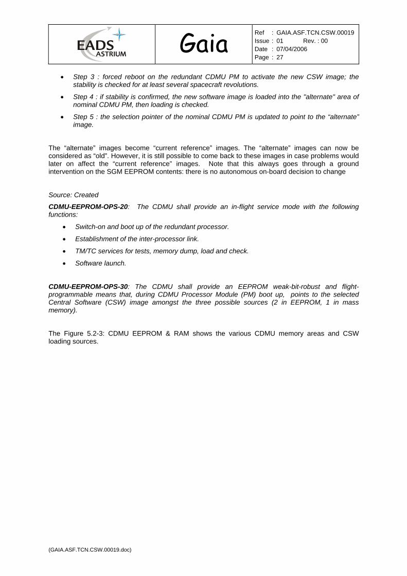
• Step 3 : forced reboot on the redundant CDMU PM to activate the new CSW image; the stability is checked for at least several spacecraft revolutions.
• Step 4 : if stability is confirmed, the new software image is loaded into the "alternate" area of nominal CDMU PM, then loading is checked.
• Step 5 : the selection pointer of the nominal CDMU PM is updated to point to the “alternate” image.
The “alternate” images become “current reference” images. The “alternate” images can now be considered as “old”. However, it is still possible to come back to these images in case problems would later on affect the “current reference” images. Note that this always goes through a ground intervention on the SGM EEPROM contents: there is no autonomous on-board decision to change
Source: Created
CDMU-EEPROM-OPS-20: The CDMU shall provide an in-flight service mode with the following functions:
• Switch-on and boot up of the redundant processor.
• Establishment of the inter-processor link.
• TM/TC services for tests, memory dump, load and check.
• Software launch.
CDMU-EEPROM-OPS-30: The CDMU shall provide an EEPROM weak-bit-robust and flight-programmable means that, during CDMU Processor Module (PM) boot up, points to the selected Central Software (CSW) image amongst the three possible sources (2 in EEPROM, 1 in mass memory).
The Figure 5.2-3: CDMU EEPROM & RAM shows the various CDMU memory areas and CSW loading sources.

Gaia Ref : GAIA.ASF.TCN.CSW.00019
Issue : 01 Rev. : 00 Date : 07/04/2006 Page : 28
(GAIA.ASF.TCN.CSW.00019.doc)
ProcessorModule
ProcessorModule
SystemMassMemory
SystemMassMemory
EEPROM3 Mibyte4 Mbyteoption
PROM64 Kibyte
SDRAM8 Gibit
SDRAM8 Gibit
EEPROM3 Mibyte4 Mbyteoption
PROM64 Kibyte
TelemetryTelecommandReconfiguration
SGMEEPROM256 Kibyte
CONFIGEEPROM256 Kibyte
TelemetryTelecommandReconfiguration
SGMEEPROM256 Kibyte
CONFIGEEPROM256 Kibyte
RAM6 Mibyte
RAM6 Mibyte
BootCodeCSW Boot
Code CSW
TC
TM
TC
TM
Figure 5.2-3: CDMU EEPROM & RAM

Gaia Ref : GAIA.ASF.TCN.CSW.00019
Issue : 01 Rev. : 00 Date : 07/04/2006 Page : 29
(GAIA.ASF.TCN.CSW.00019.doc)
Appendix 1: Maxwell SCS750 featuring SEC/DED EDAC in front of EEPROM
Ultracapacitors Microelectronics High-Voltage Capacitors
Detailed SCS750 Block Diagram
PPC 750FX
TM
R L
OG
IC
Memory Controllers,T imers (3), Interrupts,
DMA, UART (1)W atchdog Tim er
Mission T im erPPC 750FX
PPC 750FX SDRAM InterfaceDouble Device
Correction Reed-Solomon
EEPROMInterface
SEC/DED EDAC 7.0MB User EEPROM
SDRAM256 MBytes
0.5MB Secondary SuROM0.5MB Prim ary SuROM
Fro
nt P
anel
Test
Co
nne
cto
r
cPC
I Bac
kpla
ne
Con
nec
tors
PCI Target
PCI-PCIBridge
LOCAL PCI BUS (32 bit, 33MHz)PMC #2
Rad-Hard/Rad-TolerantSEU Immune Component
Upset Mitigation ByArcitectural Design
PMC #1
Actel RT-AXS SEU Immune FPGA
Actel RT-AXS SEU Immune FPGAPEM/EngineeringUse Only
Fro
nt P
anel
Flig
ht C
onn
ecto
r
M IL-STD-1553BC/RT/MTRad-Hard(Optional)
Power Input: 3.3V / 5V
Timer Synch# Signals (input/output) [J3 Connector]
Synch/AsynchSerial
CommunicationsController (SCC)
(2)
GPIOGeneral
Purpose I/OController(32 I/O's)
SystemTimers32 Bit
(3 Timers)
1553Interface
Logic
3.3V CMOS, 16 Discretes shared with Backplane 3.3V CMOS, 32 Discretes [J3 Connector]
LVDS Standard, RS-422 Option [J3 Connector]
JTAG/PowerPC ICE
CPU Error (3)Voltage Sense Output
UART (LVDS)
FLIGHT/FLIGHT#
Inject PPC Errors (3)
FT_RESET#
Main Memory
cPCIArbiter
PCIArbiter
8 channel arbiter
cPCIInterrupts (4)
33 MHzOscillator
Low-SkewClock Drivers
Local PCI Clocks (8)cPCI Clocks (7)
50 MHzOscillator
To FPGA's,PPC's, SDRAM's
Clock Distribution
SYSCON Clock
cPCI Bus, 3.3V32 bit, 33MHz
PCIMaster
PCITarget
System Controller Chip
PCI-IF Chip
EEPROM Write Enable (9)[J3 Connector]
FP_RESET#FP_HALT#
XFMRCoupled
XFMRCoupled
Up to 800MHz, >1,800 M IPS
Low-SkewClock Drivers

Gaia Ref : GAIA.ASF.TCN.CSW.00019
Issue : 01 Rev. : 00 Date : 07/04/2006 Page : 30
(GAIA.ASF.TCN.CSW.00019.doc)
DISTRIBUTION LIST
Overall document Summary Action Information ESA/ESTEC Jean-Pierre BALLEY X Giovanni COLANGELO X Giuseppe SARRI X Alistair WINTON X ESA/ESOC John DODSWORTH X Robert FURNELL X EADS ASTRIUM SAS Pierre-Luc BAZIN X Philippe CHARVET François CHASSAT Eric ECALE X Frédéric FAYE X Stéphane GALLET X Daniel HERBIN X Anouk LABORIE X Christian LEBRANCHU X Patrick LELONG X Denis MARCHAIS X Xavier MOISSON X Michel PENDARIES X Philippe PERES X Vincent POINSIGNON Pierre POUNY X Gilles ROUGIER X André SOBECZKO X Jean-François SOUCAILLE X Jean-Paul VORMUS X EADS ASTRIUM LTD Omar EMAM X Steve KING X Baljit MATHARU X Robert PURVINSKI X Rosalind WARREN X EADS ASTRIUM GmbH Rudi Kerner X Marcus Schelkle X

Gaia Ref : GAIA.ASF.TCN.CSW.00019
Issue : 01 Rev. : 00 Date : 07/04/2006 Page : 31
(GAIA.ASF.TCN.CSW.00019.doc)
End of document