Embed Size (px)
Citation preview
Gaertner-Peck Spectrometer Manual By Professor Edson R . Peck
TABLE OF CONTENTS:
Basic Theory a n d Description of the Instrument ... 5 ........... Explanation of Instrument Assembly 6
..................... Specifications a n d Parts List 7
............ Operat ion of Telescope a n d Col l imator 8
Preliminary Adjustments ............................. 9 Focusing the Telescope ........................... 9
.......................... Focusing the Col l imator 10 ....................... Setting the Telescope Axis 10
.......................... Leveling the Col l imator 11
................................. Adjustment of Slit 1 1 ............................... Leveling the Object 1 1
....................... I l lumination of Col l imator 11
................................ Suggested Experiments -12 1 . Specular Reflection from a Plane
.......................................... Surface 12 ............ . 2 Refractive Index a n d Dispersion 13
........................ . 3 Fraunhofer Dif fract ion 15 . 4 Plane Dif fract ion Gra t ing .................... 16
............................ . 5 Plane Polarizat ion 19
. ..................................... 6 Ellipsometry 21
........................ Gaertner Scientific Instruments 23
Copyright 'i) 1963 by Gaertner Scientific Corporation. Chicago. I l l inois 60614 . Permission is granted to quote statements or portions provided credit i s given to Gaertner Scientific Cor- poration . No other reproduction in any form is permissible without written authority f rom this company .

ABOUT THE AUTHOR. . . Professor Edson R. Peck is recognized as a leading educator and one of the foremost authorities on the subject of physics and spectrometry.
As an educator, Professor Peck's distinguished career included many years with Northwestern University in Evanston, Illinois. He served Northwestern as Research Associate and Instructor from 1942 to 1945, when he received his Ph.D. from the University of Chicago. In 1946 he was made Assistant Professor, and in 1949, Associate Professor. He is now associated with the University of Idaho. Professor Peck's books and numer- ous technical papers have contributed greatly to our fund of knowledge in many scientific areas. He has authored a variety of signed articles in reference sources such as the American Peoples Encyclopedia, the Ency- clopaedia Britannica, and Eshbach's Handbook of Engineering Fundamentals.
Professor Peck is one of the leading workers in spectros- copy, optics, interferometry, and applications in inter- ferometry to solid state problems involving dimensional changes. His studies have brought him a number of research grants from private research organizations, from government, and from educational institutions. In addition, he has served as consultant to a number of private companies, including Gaertner Scientific Corporation.
Gaertner Scientific is indebted to Professor Peck for his work in preparing the information presented in this manual. His invaluable help in the development of this new student spectrometer, and the series of experiments presented in the manual, are a major contribution toward simplifying classroom instruction and furthering the understanding of Divided-Circle Spectrometry.
GAERTNER SCIENTIFIC

Basic Theory and Description of the Instrument
A spectrometer is basically an instrument for measuring visually the angular detlectians of light rays abaut a single axis. The name arises from one of the applications of such measurement. Since angular devia- tions produced by a prism or grating are wavelength dependent, the emergent light from either of these components is dispersed into a spectrum in which wavelength is a function of angle.
The wave nature of light involves the impossibility of isolating a ray of light. Precise angle measurements cannot be made on a light beam of very narrow width because of the spread of direction necessarily accom- panying a limitation of beam width. This phenomenon is called diffrac- tion. It follows that the incident and emergent light is not to be chan- neled, as one might naively suppose, through a pair of slits supposed to pass only one ray. See Fig. 1. Instead, a beam of some width is produced by a collimator as shown in Fig. 2 and 3. A narrow vertical slit S is in the focal plane of a lens LI corrected a t least for spherical and chromatic aberration. Light from a source outside the collimator passes through the slit and fans out to fill the collimator lens. The resulting beam as seen from above has wave fronts essentially straight and parallel; that is, the beam is described by rays which are nearly straight and parallel to one another in their projections on a horizontal plane. An uncertainty relation describes the angular spread resulting from diffraction in a beam of width D, in terms of the wave number vector CT of magnitude l /h in the ray direction. The product of D with the uncertainty in the component of rr parallel to D is of the order of magnitude of unity. This uncertainty is crAB = AO/A. Then D [(AH)/A] -- 1, or
Figure 1 Because of diffraction, a pair of slits does not produce a single ray direction
- Figure 2 Plan view of a collimator
Equation (1) gives the natural limit of accuracy of the spectrometer measurements.
I t should be remembered that only the light through tha t part of the slit halfway between its ends, presumably on the axis of the collimator lens, lies in a horizontal plane after passing the lens. An elevation view of the beam as in Fig. 3 shows rays directed above the horizontal from ir' the bottom end of the slit, rays directed below horizontal from the top of the slit, as well as the rays from the center of the slit. Each point I
Figure 3 of the slit produces a separate, completely collimated beam. In other Elevation view of 0 collimator
terms, the slit is imaged point for point (stigmatically) a t infinity by the collimator lens.
The optical instrument for viewing emergent light is a telescope, whose basic function is to accept a wide beam and also to produce angular magnification, so that angular deviations smaller than the one minute of angle detectable by the human eye are rendered visible. The telescope has a built-in cross hair providing a visual reference direction fixed with respect to the mechanical orientation of the telescope tube. An astronom- ical telescope is used, since inversion of the image is of no consequence. As shown in Fig. 4, the cross hair X is exactly in the focal plane of the objective Lz, so that its vertical line intercepts rays which entered the lens in a particular beam collimated as seen from above, that is, all rays Figure 4
whose projections on the horizontal plane have a particular direction. Telescope with cross hair

Stated otherwise, the plane of the cross hair is optically conjugate to an infinitely distant object, in particular to the slit image produced by the properly adjusted collimator. The real slit image as formed by both collimator and telescope lenses, falls indeed into the focal plane occupied by the cross hairs. The position of the cross hairs is therefore not a subjective or arbitrary matter. The adjustment of the ocular (0) is separate from that of the cross hairs. The function of the ocular may be conceived as being that of a simple magnifier used to view the focal plane of the telescope objective. The adjustment of the ocular may be made according to personal preference, although for persons of normal or corrected vision it is well to focus so that the final image presented to the eye is at a considerable distance. A single adjustment will then be satisfactory for all viewers with adequate distance vision.
Explanation of Instrument Assembly
In its mechanical details, the Gaertner-Peck Spectrometer is simple and functional. An overall view is shown in Fig. 5. The collimator (C) is fixed in position, except for an altitude adjustment obtained by mount- ing the objective end in a horizontal shaft and supporting the slit end by a vertical adjusting screw (Al). By this means the slit can be centered so that light from its central part is made horizontal. The entrance slit (S) has a screw adjustment for width. Closure is by spring force, opening is positive from the screw; thus the slit jaws, beveled to a knife edge, are protected from damage. The collimator focus is adjusted by sliding the tube in which the slit is mounted within the tube carrying the objective. The focus locks by a clamp screw accessible through a hole in the side of the collimator mount, the hole being closed by a snap-in button B1 after adjustment. The slit may be rotated slightly to make i t vertical, by use of the play of its focusing tube under the clamp screw. No lateral or longitudinal displacement of the collimator as a whole is required or provided. Such displacements are irrelevant in working with collimated light, except for the requirement that the beam of light must be rather fully transmitted through the instrument. To this purpose the factory adjustment is sufficient.
Accessory 11 00G Grating Holder
The telescope (T) is mounted in a manner partly similar to the colli- mator. Its focus adjustment, with set screw accessible through button (B2), changes the cross hair position, allowing in addition a slight rota- tion for making one cross hair vertical. The ocular (0) slides within the tube in which the cross hair assembly is mounted, for adjustment of visual focus. The cross hairs are stretched in a frame which slides stiffly in its tube, but which can be pushed out for replacement of broken hairs.
The telescope has a degree of freedom lacking in the collimator, the principal motion of the entire instrument: rotation about a well defined mechanical axis, which lies in what is to be called the vertical direction. It is this rotation which is precisely measured by the divided scale (M), read by vernier index (V) to the nearest minute of angle. As an aid in taking vernier readings, a viewing lens (R) is provided. The telescope rotation is free when the large clampscrew (F) is released. When (F) is tightened, a fine motion of the telescope over a limited range results from rotation of screw (J).

The optical component upon which measurements are to be made is I mounted upon table iP). A prism can be laid directly upon (Pi. A grating, .--r-.s
mirror or plate can be held in a grating holder accessory fitting into hole \ -..c* . ,..y"- .l. ~m-. : *. --. -*. .r
(W) in the table. The table rests kinematically upon three screws (HI, .$": , * $
Hz and Hz), disposed a t the corners of an equilateral triangle. A spring is .$----'k& . ,lL '
pulling the table down against the screws makes the table secure from +:*a. <,d<::;i;;i -2..:*%*,* r,, -,~ ", .< ~\ - //
accidental upsetting. These provide both a leveling and a height adjust- * ---> -.*, ,.=/ --;- IF*--- /....-'.
ment for the table. The entire table mount also rotates about the vertical. An accessory Protractor (N) with Index (I) is available to be used for Accessory LI 03Y
certain measurements requiring only secondary accuracy. Prism Table Protractor
Figure 5
C col l imator
S slit
Li, Lz objectives
AI, Az vert ical adjust ing screws (sh ipped in r e p o r o t e p las t i c b o x ;
0 ocular
B i , Bz snap- in buttons
M principal a n g l e scale
V vernier i n d e x
R viewing lens
F c l a m p screw for f i n e motion
J ad just ing screw for f i n e motion
P prism t a b l e
HI, H z , H 3 leve l ing screws
O v e r a l l V i e w of t h e Gaer tner -Peck
Spectrometer
N a u x i l i a r y a n g l e scale for t a b l e
I i n d e x for t a b l e position
T telescope
SPECIFICATIONS
I I I -7 BASE DIVIDED CIRCLE SCALE VERNIER PRISM TABLE
VERTICAL M O T I O N LENGTH- EYEPIECE TO SLIT SEPARATION-TELESCOPE A N D COLLIMATOR OBJECTIVE HEIGHT OF OPTICAL AXIS EYEPIECE - GAUSS RAMSDEN RETICLE-CROSS HAIRS OBJECTIVES
APERTURE FOCAL LENGTH
I
3 3 0 mm D l o . 190 mm D i o Smol l Div. ' ;2 '
Reodr to 1 Min. 6 3 mm D i o . 1 9 mm 4 5 0 mm 1 4 0 mm 2 1 5 mm
14X Power 90' Achromatic 2 0 mm 1 3 0 mm
ACCESSORIES
PRISM TABLE PROTRACTOR ILLUMINATOR POLARIZING ASSEMBLY COMPLETE OBJECTIVE POLARIZERS (2) EYEPIECE POLARIZER GATE DIAPHRAGM G R A T I N G HOLDER REPLICA TRANSMISSION G R A T I N G PRISM, 9 0 FLINT PRISM 6 0 ADJUSTING PLATE STEEL REFLECTING SURFACE FRONT SURFACE MIRROR QUARTER W A V E PLATE (MERCURY) QUARTER W A V E PLATE (SODIUM)
Available f r o m G o e r t n e r Scient i f ic C o r p

Operation of Telescope and Collimator
Figure 6 Gauss-Rarnsden eyepiece ( 1 4X)
Accessory 11 031 Gauss eyepiece Illuminator
An important modification of the spectrometer telescope is made by the Gauss eyepiece and illuminator sketched in Fig. 6. A thin piece of trans- parent glass (Dl, of the sort used for microscope cover slips, is located between the lenses of the eyepiece, making an angle of 45" to the optic axis. This diagonal plate transmits the rays entering the eyepiece from the objective with practically no refraction and only about 10% intensity loss. Its purpose is to receive light from the illuminator via a hole (K) in the side of the ocular and reflect i t out towards the objective, so back- lighting the cross hair (XI. The illuminator fits around the eyepiece, and contains essentially a small lamp (El, powered by a transformer fitting directly into a 60 cycle 120 volt A.C. socket, and a ground glass dif- fusing screen (G).
The telescope with Gauss eyepiece becomes an autocollimator. It fills the dual functions of illumination and viewing. As illuminator i t does not provide a collimated beam in the sense in which the collimator does, for i t lacks a slit. Nevertheless if the telescope cross hair is in the focal plane of the objective, the backlighted cross hair is imaged a t infinity by the objective: light from the cross hair itself is in this sense collimated, for each point on the cross hair gives rise to a collimated beam outside the objective. If the light emerging from the telescope is reflected fiom a plane surface back into the telescope, the returning image of the cross hair is likewise in the focal plane of the telescope objective; for a plane reflection preserves the property of collimation, forming an image a t infinity of an object a t infinity. The observer therefore sees the cross hairs directly through the eyepiece, and also sees in the same focal plane the return image of the cross hair, provided this image returns close to the axis of the telescope. If the "telescope axis" is now defined as tha t axis through the center of the cross hair and the second nodal point of the objective, coincidence of the primary and secondary images of the cross hairs means that the plane reflecting surface a t which the auto- collimator is directed is exactly normal to the telescope axis. Thus the autocoll imator i s a precise indicator of t h e normal direction of a plane reflector.
The foregoing discussion presumes exact focusing of the telescope, tha t is, location of the cross hair exactly in the focal plane of the objective. Suppose instead that the cross hair is too close to the objective. There is a very general theorem of geometrical optics stating tha t for any axially symmetric image system, a motion of object along the axis in the sense of incident light causes the image to move in the sense of emergent light. Therefore a displacement of the backlighted cross hair towards the telescope objective causes its return image to move back away from the objective. The primary and secondary cross hair images as viewed through the eyepiece are now no longer in the same focal plane. The observer thereby has a test for focusing of the telescope, one which is perfectly objective and very precise provided a good adjusting plate is a t hand.
The Gaertner-Peck Spectrometer provides freedom for making the adjustments which are significant in obtaining accurate measurements. I t is valuable for the student to carry out a complete adjustment pro- cedure, for in so doing he almost surely gains an understanding of the

optical principles and mechanical features of the instrument. A complete adjustment is presupposed for each of the experiments suggested in this manual.
Focusing the telescope The position of cross hair relative to ob- jective is the critical adjustment. In order to see the cross hair, however, it may be necessary first to adjust the eyepiece. The cross hair may be seen sharply when the cross hair image as formed by the eyepiece lies within the observer's range of accommodation. Sliding the eyepiece towards the cross hair moves the image nearer to the observer: for the image moves in the same sense relative to the ocular as does the object. Thus when the eyepiece is far in, the image is close and the eye must be accommodated for near viewing. The normal eye is relaxed for distant vision; consequently i t is well to set the eyepiece nearly as far ou t as will permit distinct vision of the cross hair. This adjustment is not critical: a range of settings is possible, and the adjustment may be changed a t will during the course of the work.
Preliminary
Adjustments
The cross hair may now be set relative to the objective by moving the tube containing the cross hair and the ocular. The simplest procedure is to view a distant object through the telescope. Simultaneous visual sharpness of the cross h-air and the distant scene is not the most sensitive criterion of correct focus. The observer should learn to use the criterion of parallax. The eye is moved across the exit pupil of the telescope by a lateral motion of the observer's head, and any relative displacement of the cross hair to the distant object is noted. If, as the eye is moved to the right, the cross hair moves to the right across the distant scene, it follows that the cross hair image lies beyond the image of that scene: for a more distant object appears to follow the observer's motion past a closer one. The cross hair must then be adjusted by moving it a u q from the objective of the telescope until the parallax disappears; for when it disappears, and only then, do the two images coincide. The condition of no parallax,
Figure 7 Half-angle of incident pencil from a distant object
indicating correct focus, is very striking once seen: the cross hair seems fixed on the distant object. An astute observer may find it impossible to fulfill the condition exactly over the entire field in which the cross hair remains visible. He is then detecting small aberrations in the telescope objective. The focus is as good as necessary if the parallax seems to reverse over the visible field.
It is worth asking how distant must the obiect be for a reasonable - approximation to the desired focus a t infinity. Consider the angle p between the telescope axis and an outside ray of the incident pencil from a point object on axis a t distance x from the objective, as in Fig. 7. This angle is, in radians, p = ( D / 2 ) l x , where D is the diameter ofthe objective. One answer to the question is obtained by equating this angle to the angle of resolution of the telescope, which is 1 .22 AID according to Rayleiah's criterion.
A simpler point of view is to consider the sagittal distance in the spherical wave front from the distant object, the distance by which the edges of the wave front lie behind the plane tangent to its vertex, as shown in Fig. 8. A general criterion for good optical image formation is that optical paths ought not to be inaccurate by more than one-quarter wavelength.
Figure 8 Sagittal distance

The sagittal distance is ([D/2I2)/2x. Equating this to A14 leads to
Accessory 11 00AP Adjusting Plate
The difference between equations ( 2 ) a n d ( 3 ) is negligible, both being estimated tolerances. The student is left to compute x for the size of objective supplied with this instrument.
The Gauss eyepiece described in the introduction permits a focus adjustment to be made within the precision of an available adjusting plate accessory. Hopefully, this might be quarter-wave flatness over an area equal in size to that of the telescope objective. A prism face, a front- surface plane mirror, or a glass plate with plane faces serves the purpose. The theory of this adjustment has been described in the introductory section. It remains only to add that parallax is again the criterion for common focus of the cross hair and its return image. It is well, but not essential to perform a preliminary focus on a fairly distant object, a t least down a corridor, in order to facilitate finding the return image of the cross hair.
Focusing the collimator This operation is trivial once the telescope is focused. The slit is made narrow and is illuminated. The telescope is directed into the collimator, so that the slit image is seen. The collimator is then focused until parallax between the slit image and the vertical cross hair image vanishes. This adjustment may be found to be de- pendent on the wavelength of illumination. If so, one observes chromatic aberration in the objectives.
Setting the telescope axis in a horizontal plane BY defini- tion, the horizontal plane in the spectrometer is normal to the principal mechanical axis. It is important for work of greatest precision that the horizontal cross hair, or the intersection of the two cross hairs, should mark the height of horizontal rays. The deviations produced by a prism or a grating, when projected on the horizontal, have a quadratic de- pendence upon small vertical components of the ray vectors. It is this which produces the curvature of spectral lines. A properly leveled telescope permits the observer to single out the horizontal rays for measurement.
The leveling adjustment of the telescope is best accomplished with the aid of the Gauss eyepiece and a glass plate having faces both accurately plane and nearly parallel to one another. Such a plate returns either a single image of the illuminated cross hair, or if the faces are slightly out of parallel, two closely spaced images coming from reflection a t the two faces. Rotation of the plate through 180" about the principal mechanical axis leaves its normal in the same direction if and only if this axis lies parallel to the faces of the plate. This condition may be achieved by use of the table leveling screws, the criterion being that the return image of the cross hair as seen in the telescope keeps its same height after a 180" rotation of the plate. If now the vertical lies parallel to the faces of the plate, then these faces lie in a vertical plane and their normal direction is horizontal. The telescope axis can then be made horizontal simply by leveling i t so that the horizontal cross hair and its return image coincide.

Leveling the coil i mator After the telescope has been made horizon- tal, it is a simple matter to level the collimator. It will hardly be found so far out of level that the light from no part of the slit is horizontal. Nevertheless, it is convenient and more aesthetic to level the collimator so that the light from the center of the slit is horizontal. The slit image then is bisected by the horizontal hair of the leveled telescope. The colli- mator objective functions best in this condition, for then the light to be used issues from the collimator parallel to the lens axis.
Adjustment of slit The appropriate slit width for any particular work is a matter somewhat of personal preference. For accuracy of setting the cross hair on the slit, the slit should be narrow; for greater illumination, broader. One should bear in mind that there is no point in narrowing the slit beyond the point where its angular width, as seen from a distance equal to the focal length of the collimator objective, is less than the spread due to diffraction in a beam of width equal to the diameter of the objective. When the slit is nearly closed it may appear broken, because of specks ofdust or dirt on its knife-edgedjaws. The jawsmay becleanedby opening the slit and running a wooden matchstick along the knife edges.
The slit should in principle have another degree of freedom besides its width and its focal position which was discussed as Adjustment 2. In order that a portion of its length, rather than just one point on it, should be useful in observing, the slit should be vertical, that is parallel to the principal mechanical axis of the spectrometer. The slit is made nearly vertical in manufacture. A slight play in its focusing slot may be used to bring the slit sufficiently near to vertical, as may be estimated by reference to the horizontal lines of motion of each point of the slit image viewed in the telescope, when the telescope is swung about the main vertical axis.
Leveling of the object to be examined The optical component placed on the spectrometer table will generally be a transparent flat, a mirror, a grating, or a prism. In all these cases, the Gauss eyepiece may be used, once the telescope is leveled, to observe whether an optical surface of the component is vertical. The leveling screws of the prism table should be used to realize this condition by making the return image of the cross hair have the same height as the direct image. When this condition is fulfilled, horizontal rays incident on the component being tested lead to horizontal emergent rays. More specific instructions are suggested in several of the experiments.
Illumination of the collimator An adjustment of external appara- tus is required to obtain proper illumination of the collimator. It is essential to the most accurate collimation of light that a full beam width be obtained, as explained in the Introduction. It follows that light passing through the slit should fan out enough to fill the collimator objective. Unless the slit is extremely narrow, the angular size of the beam of light between slit and collimator is not primarily due to diffrac- tion a t the slit but must be produced by allowing a beam of at least this same angle to fall upon the outside of the slit. This angle is 2 arctan D/2f , where D is the diameter of the collimator lens and f i t s focal length. Its more usual measure is the focal ratio or f-number of the collimator, flD. The reciprocal of this quantity, Dlf , may be called the relati~le aperture of the collimator.
Often it is convenient to place the light source close enough to the collimator slit as to subtend a t the slit an angle large enough to fill the collimator. In this case, no condensing lens is needed and optimum illumination is obtained. Whenever this is not possible, because the source area is small or physical limitations are present, a simple con- verging lens may be used to image the source on the slit. This lens need not be particularly free from aberrations, but its relative aperture as used must be as great as that of the collimator: that is, its ratio of diameter to image distance must be as large as the ratio Dlf of the collimator. This requirement will sometimes mean that a reduced image rather than magnified one is chosen when these alternatives exist.
When a condensing lens is used, some difficulty may be encountered in lining up the three elements of collimator, condensing lens, and source. A straightforward procedure is to line up first the source and collimator, without the condensing lens. The slit may be opened quite wide, and the light viewed through the collimator lens by eye, the eye being quite far from the collimator and sweeping horizontally and vertically to see where the illumination lies on the collimator lens. Alternatively, a white piece of paper may be used as a screen to catch the light passing through the collimator. It is easy to center this beam by horizontal and vertical motion of the source. The source now being on axis of the collimator should require no readjustment when the condensing lens is inserted. The lens position is then correct when the source image is centered on the slit. If the source should subsequently be moved while the condensing lens remains in position, or if sources should be inter- changed, it is not necessary to repeat the whole procedure. The conden- sing lens being in position on the axis of the collimator, only the source need be moved until its image falls properly upon the collimator slit.
Suggested Experiments
1. Specular Reflection from a Plane Surface Investigation of this simple case may be very useful in becoming acquainted with the spectrometer. The results obtained are easily checked against theory, to give an index of the precision to be expected from the instrument and from the student's technique in using it.
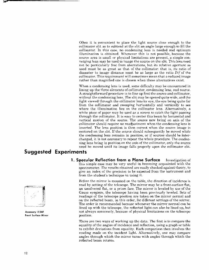
Accessory 11 36F Front Surface Mirror
Before the mirror is mounted on the table, the direction of incidence is read by setting of the telescope. The mirror may be a front-surface flat, an unsilvered flat, or a prism face. The mirror is leveled by use of the Gauss eyepiece, the telescope having been previously leveled. Sets of readings of the telescope position are taken on the mirror normal and on the reflected beam, in this order, for different settings of the mirror. The order is recommended because whenever the mirror normal can be lined up with the telescope, the reflected light can also be lined up, but not always conversely, because of physical limitations on the telescope position.
There are two ways of working up the data. The first is to compare the equality of the angles of incidence and reflection, using a graph or table to exhibit deviations from equality. Each comparison then involves the reading made on the incident light. Alternatively, one may compare angles through which the mirror turns with angles through which the reflected beam rotates.

An important part of the law of regular reflection has up to this point been ignored, the coplanarity of the incident ray, normal and reflected ray. It is interesting to mark the part of the collimator slit from which horizontal rays come, by fastening across the slit a fine wire or thread. A little soft wax map be used as adhesive, and the wire adjusted until the dark spot of the slit is on the horizontal cross hair of the telescope when the collimator is directly viewed. The test of coplanarity is that when the mirror normal is made horizontal, this dark spot is seen as horizontal also in the reflected beam. An instructive exercise in a three-dimensional situation is to throw the mirror normal deliberately a little out of horizontal, and to watch the height of the dark spot of the slit as a function of the horizontal projection of the angle ,of incidence. As the incidence approaches grazing, the spot seen by reflection will be observed to approach the horizontal. This phenomenon lends itself to illustration of the vector law of reflection: r' = r - 2(r.n)n, where r ' , r are reflected and incident ray vectors, and n is a unit vector normal to the mirror.
Refractive Index and Dispersion Using a Prism The refrac- tive index of transparent optical materials may be measured with the spectrometer if a sample of material is available in the form of a tri- angular prism with two planar, polished faces. Liquid samples may be observed in a hollow prism with windows of thin, plane-parallel glass. The faces of the prism through which light passes are the refracting faces, and their intersection will be called the refracting edge. The refracting angle, the a ~ g l e a t which the refracting faces meet, is generally about 60". This angle permits light to be transmitted by ma- terials having refractive indices less than 2. The theory of the prism shows that the deviation produced by the prism, the angle between incident and emergent light, js minimum when the ray in the prism is normal to the bisector of the refracting angle. Because of the simplicity of analysis, and the superior quality of the image a t minimum deviation, measurements are usually restricted to this condition. Minimum deviation is readily observed and maintained. Rotation of the prism table causes motion of the observed slit image. This motion slows to a stop and reverses a t the condition of minimum deviation.
Accessory 171 1 60' Flint Prism
Elementary prism theory applies only to rays entering, and hence remaining, in a plane normal to the refracting edge, the plane also of the two face normals. Evidently it is important that this symmetric plane of the prism be horizontal in the spectrometer, that is be normal to the principal axis of the spectrometer: for the spectrometer measures angles in the horizontal plane. An equivalent requirement is that the refracting edge of the prism be vertical, that is parallel to the spec- trometer axis. The required two-dimensional leveling operation of the prism is easily performed by use of the leveling screws of the prism table, provided the prism is set on the table so that the lower edge of one refracting face, AB, lies perpendicular to a line joining a pair of adjusting screws a and b. See Fig. 9. Prism face AC is now also normal to a line between screws, ac. The line ab is the axis about which the prism table Figure 9
is rotated by adjustment of the third screw, c. Now the normal to prism Correct position of a prism ABC . -
face AB may be made horizontal, as tested by the Gauss eyepiece: Sub- relative a, b, C, of to the the prism leveling table screws
seauent mani~ula t ion of screw c. in order to make the normal of the other face AC horizontal, leaves the normal to AB unaffected, since this

\ Figure 10 One method of measuring the refracting angle of a prism
normal is parallel to ab. Thus the two steps in leveling the prism are made independent. It is wise nevertheless to recheck the leveling of AB, since the orientation of the prism on the table may have been inexact. Any necessary correction should now be made with screw b, so as to minimize disturbance of the adjustment of AC.
The measurements to be made are in two classes: first to determine pre- cisely the refracting angle of the prism, and then to measure deviations produced by the prism. A direct measurement of prism angle results from clamping the prism table to prevent rotation, and using the Gauss eyepiace to observe the angular positions of the two face normals. Another method is to turn the prism table until the light from the colli- mator strikes both prism faces simultaneously, as in Fig. 10. The angle p between the two reflected rays is exactly twice the refracting angle a. This follows by the theorem that rotation of a plane mirror rotates reflected light through the double angle; for if a double-sided mirror in the direction of AB were turned through angle a to coincide with AC the reflected ray would turn continuously from n, to r2 through the angle p. The precision of the method is theoretically less than that obtainable by the Gauss eyepiece because of the splitting of the beam width in two. This point is however of no practical importance in the present instru- ment, which allows angle readings to the nearest minute.
For measurement of refractive index alone, a sodium light source is suitable. The aperture of the instrument just allows resolution of the sodium doublet, so that setting on the refracted light may be made a t the center of the apparent slit image. A more interesting experiment involves settings on several lines of some simple spectrum, such as that of mercury, hydrogen, or helium. Hydrogen is especially important for comparison with s t a ~ d a r d data, sigce the C and F lines (in Fraunhofer notation), a t 6562.8A and 4861.3A, respectively, have long been used in tabtlations of refractive index. To a lesser degree, the G' line a t 4340.5A is used. If measu~ement is also made on the sodium D lines of mean wavelength 5892.9A, one can compute the v -value, or reciprocal dispersive power of the prism material:
% - 1 ve- T F - 77c
(4)
It is important in work with the refracting prism to notice that the slit image is curved. Readings should be taken on that part of the slit image corresponding to horizontal light. If the slit is exactly vertical, this point will be a t the vertical tangent to the curved image; but in any case the horizontal cross hair of the telescope, adjusted to be horizontal, may be used as a reference. The theory of refraction shows that if the incident (and hence the emergent) light is a t a small angle $ out of the symmetric plane of the prism, then the rays projected onto this plane have such directions as would result from a refractive index Nen of prism relative to surrounding air, instead of the actual index n:
Since N > 1, Nerr > n. Therefore the ends of the slit image point in the sense corresponding to larger refractive index; and this, in normal dispersion, is towards the violet end of the spectrum.

No other comments are needed concerning the measurement ofminimum deviation angles, except that care should be taken in setting the prism initially on the table so that full incident and emergent beam widths are transmitted. It is assumed that the students are-familiar with the relation of refractive index to the angle Dm of minimum deviation: -
t~ + Dm sin
. Fraunhofer Diffraction. Resolution of Prism Spectrometer. One-dimensional Fraunhofer diffraction occurs in the spectrometer when the light beam between collimator and telescope is obstructed by an aperture having vertical edges. Accessories for the spectrometer include a gate diaphragm with adjustable jaws which can be placed over the objective of the collimator. One can readily observe vertical fringes
Accessory 11 03D in the telescope field when the aperture is narrowed. A quantitative
Gate Diaphragm experiment is possible, by setting the telescope so that the vertical cross hair coincides with successive fringes, and reading the angles of diffrac- tion. While this method is not as accurate as the use of a micrometer eyepiece, it is at least a direct angle measurement. The fringe spacing may be compared with the aperture width w by simple theory, which predicts minima a t angles 4 satisfying
w s i n 4 = N A , N = = ? 1 , 2 , . . . (7) When 4 remains small, a sufficiently good approximate formula is
T
w = 1 cos 8 = 1 sin 6 - 9 ) q - 0 ) (9) Figure 1 1
for incidence at angle 8. The final approximate form of Eq. (9) is valid Prism face used as for values of 9 measured in radians, such that [(n-12) - 81 is very small. an aperture
A 4 L N - w (8)
C L,
The foregoing observations, even if only qualitatively performed, are helpful in appreciating the limition of spectral resolution by beam width in a prism spectrometer. This limit arises simply from the diffraction profile of the slit image. Two spectral lines are considered a t the limit of resolution when the central maximum of one falls on the first minimum of the other. The student is assumed to be familiar with the standard I
formula forresolution of a prism: A -- dn = b - (10)
Ah dA where b is the base length of the prism actually used, assuming it illuminated up to its vertex, and dn/dA is the rate of variation of re- fractive index of the prism material with wavelength. In practice, b is the difference between the path in the prism of the rays a t the two sides of the beam, as shown in Fig. 12. The student should show that b is
Another method of limiting the beam width is to reflect the collimated light from a prism face a t an angle near grazing. If the prism face AB in -
related to the beam width w a t minimum deviation by Figure 12
a+Dm a b = 2~ S ~ C (T) sin 5 (11) Light passing through a prism
at minimum deviation
' Fig. 11 has length 1, it forms an aperture of width

Accessory 11 03GT Replica Transmission Grating
Assuming the light for each of two wavelengths separated by a small interval Ah is close to minimum deviation, and approximating finite differences by differentials, one obtains from Eq. 16) an expression for the angle between the emergent directions:
a + D m ff dl1 lDr,, = 2 sec (---2--)sin 1 AA (12)
where (dnldh) Ah is the difference between the two refractive indices. Equating of ADm with the angle of diffraction of the first minimum, hlru, leads a t once to Eq. (10). Here A is strictly a mean wavelength, but to the accuracy required it may be either wavelength.
These considerations are readily checked experimentally by using the gatediaphragm and prism, observing some spectrum with a suitable close pair of lines. The gate is closed down until the two lines just appear distinct before merging, and its width is then measured. To make a comparison with theory, the dispersion dnldh of the prism material must be determined, perhaps by a previous experiment with this spectrometer, and the prism angle must be approximately known or measured. The angle of minimum deviation is easily obtained on the spectrometer: thus all quantities needed are available if the wavelengths involved are known.
A useable pair of line:, although widely spaced, is the yellow group 5 7 6 9 . 6 0 ~ and 5790.66A in the mercury arc spectrum. These are almost equally intense. Another pair of lines is the sodium doublet, 5889.95A and 5895.92A. These are rather too close for easy resolution by eye a t the magnification of the telescope, even if they are resolved by the prism.
In order to obtain maximum resolution, it is important that the slit be parallel to the refracting edge of the prism. This edge should first be made parallel to the principal axis of the spectrometer, as described in Expt. 2. The slit can be rotated slightly about the collimator axis if necessary, using the play under the focus set screw, for best resolution.
4. Plane Diffraction Grating Either a transmission grating or a reflection grating can be studied with the spectrometer. It is instructive to have several coarse gratings, which are readily available in the black- line transmission type, of different spacings, in order to see the result of increasing the number of grating lines. The cheaper replicas are worthless for this instrument, since they may be very far from flat or have non-uniform rulings. Their spectra will not bear magnification by the telescope. A good replica reflection grating of 150 or 300 lines per millimeter makes an excellent specimen, since many orders will be visible and there will generally be a pronounced blaze.
The first experimental problem, in preparation h r a n accurate study of grating diffraction, is the adjustment of the grating on the spectrometer table. Since the spectrometer measures angles in a horizontal plane, the criterion for adjustment is that incident and emergent light rays shall both be horizontal; otherwise interpretation of the measurements re- quires three-dimensional rather than two-dimensional analysis. A horizontal incident ray leads to a horizontal diffracted ray in general only when the grating rulings (lines) are vertical. A correct adjustment therefore involves rotation about two horizontal axes. Rotation about a horizontal line parallel to the grating face permits setting the face

vertical, that is to contain vertical lines. Rotation about a normal to the face completes the adjustment of the grating. Since the platform leveling screws are at corners of an equilateral triangle, the grating may be oriented on the platform so that one of the rotations is nearly unaffected by one of the leveling screws. As shown in Fig. 13, one way of meeting this requirement is to make the intersection of the grating with the table perpendicular to the line AB between a pair of screws. Adjustment of screw A or B rotates the grating about an axis neither normal nor parallel to its surface, but such rotation may be used to make the grating surface vertical. Subsequent adjustment of C leaves the grating surface nearly vertical, as it rotates the grating about the line AB, for AB is normal to the grating surface to the accuracy with which the grating is mounted perpendicular to the table. The first adjustment, of screw A or B, may be made by using the Gauss eyepiece, or by viewing the light from the collimator reflected in zero order from the grating surface. Procedures are then as described under Exper. I; the grating lines are not involved in the specular or zero-order reflection. Setting of the rulings vertical with screw C is tested by marking a horizontal incident ray. The collimator slit is crossed with a wire for this purpose, as in Exper. I. The diffracted image of the slit is then viewed in as high an order of diffraction as possible. The criterion or correct adjustment is that the marked ray emerge horizontally under all conditions of diffraction. According to the theory of the plane grating, the tangential vector components rt, r'c of the incident and diffracted unit ray vectors r and r' bear the relation
where D is the grating space, h the wavelength, N the spectral order, and i' a unit vector in the grating surface perpendicular to the rulings. The last mentioned adjustment amounts to a rotation of i' into the horizontal plane of the spectrometer. Clearly the greatest sensitivity is achieved for the largest order N.
After the grating has been adjusted, the collimator slit should be made as nearly vertical as possible. See discussion of this point under Exper. 3.
The familiar relation between the angles of incidence and diffraction for rays in a plane normal to the grating rulings follows a t once by dotting i f into Eq. (13). The quantity I ' . ~ c is then the cosine of the angle between the incident ray and the direction i', or the sine of the angle of incidence a provided the proper sign is chosen for a. Similarly z'.r; is, for horizon- tal rays, the sine of the angle P of diffraction. Fig. 14 shows positive angles a and P , with relation to an arbitrarily selected sense of the vector i f . Notice that for both reflection and transmission gratings, the zero spectral order corresponds to like signs as well as equal values of a and p. The grating equation with these conventions now reads
Nh = D (sin p - sin a ) (14) The spectral order number N is either a positive or negative integer, or zero.
Figure 13 Suggested position of a grating on the prism table
Figure 14 Examples of positive angles of incidence and diffraction for a reflection grating (top) and a transmission grating (bottom)
Several experiments may be performed with diffraction gratings. A sodium light source is suitable for verification of Eq. (14) at essentially a single wavelength, using the resonance doublet a t 5889.953A and

5895.923~. This choice has the advantage of a simple spectrum. A mercury arc presents a more varied and beautiful sight, and demon- strates overlapping ofoorders. A list of the more intenseo mercury azc lines follows: 5790.663A, 5769.598A, 5460.735A74358.328A,4077.831A, 4046.563~. An experiment will involve determination of the grating space D from some given wavelength, perhaps averaging over readings in several orders. This value might then be used in Eq. (14) to check the equation a t other wavelengths, or to make wavelength measurements.
For the most precise work, all angles must be measured on the principal angle scale of the spectrometer, the one to which the telescope position is referred. This raises the problem of determining the position of the grating normal. One method is to use the Gauss eyepiece in order to set the telescope on the grating normal. The alternative is to make use of the zero order reflection, which should be available even from a flat transmission grating, to fix the position of the grating normal through use of the law of regular reflection.
One particular way of checking the grating equation is to fix the tele- scope and rotate the grating. The auxiliary angle scale of the grating table is more convenient for this purpose than the main scale, even though the accuracy is less. The experiment is worth doing with a reflection grating because such an arrangement is used in a type of constant-deviation wavelength spectrometer. Let the rotation of the grating be measured by the angle 4 between grating normal and the bisector of the angle x between telescope and collimator, as shown in Fig. 15, with a positive increment in 4 corresponding to increase of angle /3. The student may then show that the grating Eq. (14), takes the form
NA = 2 0 cos sin d 2 (15)
With a transmission grating, grating rotation is not a convenient way of sweeping through the spectrum. It may however be of interest to show from Eq. (14'1 that for any given spectral order, except zero order, there
Figure 15 is a position for a transmission grating yielding minimum deviation, Angles for analysis of a namely when a = - P , that is, when the grating surface bisects the angle constant-deviation grating spectrometer between telescope and collimator. This conclusion may be checked
experimentally.
Two other experiments with gratings are of interest. One is a qualita- tive investigation of the distribution of light intensity in the various spectral orders. This may conveniently be investigated a t fixed devia- tion with a reflection grating, rotating the grating only and using the auxiliary angle scale for reference. A bright order (blaze) of the grating occurs when the incident and emergent rays make the equal angles of specular reflection with a flat portion of the groove profile. The student may thus be able to deduce the blaze angle, between the normal to the grating and the normal to such a flat portion of the grooves.
The other suggested experiment is investigation of the spectral resolving power of the grating, by using the gate aperture to cut down the width of the illuminated portion of the grating. The sodium yellow doublet is suitable for the test, although somewhat wide. The standard formula involves the number m of grating lines taking part in the diffraction, and the spectral order:
The gate diaphragm may be placed either on the collimator objective, or on the telescope objective. It is to be closed until the pair of spectral lines is just barely resolved. The angle between the grating normal and whichever axis has the gate aperture must be measured, as well as the width of the gate, in order to determine m.
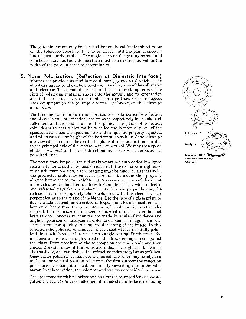
5. Plane Polarization. (Reflection a t Dielectric Interface.) Mounts are provided as auxiliary equipment, by means of which sheets I _.
\% , SC *', lailai"... * of polarizing material can be placed over the objectives of the collimator * 4
2 3 .-- , * I
and telescope. These mounts are secured in place by clamp screws. The i . . > : i: \ + X I
ring of polarizing material snaps into the mount, and its orientation %a <+- a ,, ~ I, 6 '-, ,L. 2
about the optic axis can be estimated on a protractor to one degree. , . * % _ ./
This equipment on the collimator forms a polarizer, on the telescope 1 *,*"J
an analyzer - " E - ,e - 1.->
a,,"+ *- "y \ The fundamental reference frame for studies of polarization by reflection , %: k: and of coefficients of reflection, has its axes respectively in the plane of !p- -,--.n%% - - - &,A reflection and perpendicular to this plane. The plane of reflection ++-x-~+w coincides with that which we have called the horizontal plane of the (3 spectrometer when the spectrometer and sample are properly adjusted, Polor~zers - - - and when rays a t the height of the horizontal cross hair of the telescope ,dk ~ ~ i j 3 1 - g. are viewed The perpendicular to the plane of reflection is then parallel
Analyzer to the principal axis of the spectrometer, or vertical. We may then speak of the horzzorztal and uertrml dlrectlons as the axes for resolution of polarized light. Accessory L103P
Polor~z~ng Attochment
The protractors for polarizer and analyzer are not automatically aligned Assembly
relative to horizontal or vertical directions. If the set screw is tightened in an arbitrary position, a zero reading must be made; or alternatively, the protracter scale may be set a t zero, and the mount then properly aligned before the screw is tightened. An accurate means of alignment is provided by the fact that a t Brewster's angle, that is, when reflected and refracted rays from a dielectric interface are perpendicular, the reflected light is completely plane polarized with the-electric vector perpendicular to the plane of incidence. Let the face of a glass prism or flat be made vertical, as described in Expt. I, and let a monochromatic, horizontal beam from the collimator be reflected from it into the tele- scope. Either polarizer or analyzer is inserted into the beam, but not both a t once. Successive changes are made in angle of incidence and angle of polarizer or analyzer in order to darken the image of the slit. These steps lead quickly to complete darkening of the image. In this condition the polarizer or analyzer is set exactly for horizontally polar- ized light, which we shall term its zero angle setting. Furthermore the incidence and reflection angles are then the Brewster angle in air against the glass. From readings of the telescope on the main scale one then checks Brewster's law if the refractive index of the glass is known; or alternatively, one can deduce the refractive index from Brewster's law. Once either polarizer or analyzer is thus set, the other may be adjusted to the 90" or vertical position relative to the first without the reflection procedure, by setting it to block the directly viewed light from the colli- mator. In this condition, the polarizer and analyzer are said to be crossed.
The spectrometer with polarizer and analyzer is equipped for an investi- gation of Fresnel's laws of reflection a t a dielectric interface, excluding

Figure 16
Reflection and refraction at a dielectric interface. Positive signs are shown for the electric field components in the plane of incidence.
the case of total reflection. Except for total reflection, a plane polarized incident wave is reflected as a plane polarized wave. Let EY represent the horizontal component of the incident electric field, that is the com- ponent polarized in the plane of incidence: and let E, be the vertical component, polarized perpendicular to the plane of incidence. The boundary conditions of electromagnetic theory show that the reflected wave has components E: and EI which are either in phase or 180" out of phase with the corresponding incident field components. For mono- chromatic light, in which the fields are harmonic functions of time with a common frequency, a 180" phase shift is expressed by a reversal of algebraic sign. Thus if an (amplitude) reflectance be defined for each polarization so that
E : = fi Ex: E( = I;. E ) (17) then positive reflectance means absence of phase shift, negative re- flectance means a 180" phase shift. To make these terms meaningful, conventions are needed for the positive senses of the fields. Let us choose the upward vertical as positive for the fields E?. and E:. For the x-com- ponents, let the positive sense lie to the right of an observer looking into the light beam, whether incident or reflected. See Fig. 16. Orienta- tions of polarizer and analyzer will be specified in terms of trigonometric angles in the Ex, E, or EL, E'i planes respectively. Now with these con- ventions, Fresnel's equations of reflection read as follows:
where H I is the angle of incidence and 02 the angle of refraction. When the incidence is in the less dense material, as in the present experiment where light in air is reflected off glass, H I - Hz 2 0 and 0 5 H I + 02 5 90" + H critical. In this case, r, will always be negative, while r, will change from positive to negative through zero a t the Brewster condition, when H I t 02 passes through 90'.
Now let the analyzer be set in the 135" or -- 45" plane, while the polar- izer is set a t variable angle 6 and adjusted for darkening of the slit image a t any particular angle of incidence. The student may show that the darkening is complete when
r x tan d = -
r ,. ( 20)
This measured ratio can be compared, both for sign and for absolute value, with the predictions (18) and (19) as a function of the angle of incidence. The refractive index of the glass sample must be known for the wavelength of light used, in order that 02 may be computed for each H I . It is convenient to use a prism face for the reflector, for its refractive index may be measured in a previous experiment, as described under Exper. 2. The prism has the advantage over a glass plate also in that a single reflection may be observed. A flat but not parallel-faced glass plate permits observing a n internal reflection through the other surface; but this situation is more complicated to analyze.
Equation (20) is equally true if 4 is the analyzer angle, when the polarizer is set a t the fixed ~os i t ion of 135".

6. Ellipsometry Plane polarized light is converted by reflection into elliptical polarized light, in the general case. Let the incident light a t a given point of a reflecting surface have instantaneous components of electric field,
E x = E,, , cos rc>t; E , = E,,, cos ~ c ' t 121) in the principal directions of polarization described under Exper. 5. The reflected electric field then has components
E: = r,E,,, cos i u ~ t - 6,J; E : = r. E , , cos i u ' t 8.) (22) Here I.,, and r . are absolute values of amplitude reflectance, for light polarized with electric field respectively parallel and normal to the plane of incidence. The reflectances will here be taken positive, contrary to the convention of the preceding experiment, because the phase shifts 6, and 6. are now explicitly exhibited. Only in the special case of non-total reflection a t a dielectric interface, will the phase shifts generally be either zero or 180". The sign conventions of Fig. 16 will be adhered to.
The analysis of elliptically polarized light, with special reference to study of surfaces, films, or s trata by reflection, is called ellipsometry. It is of contemporary interest, as appears from such papers as the following: F. Partovi, J. Opt. Soc. Am. 52,918 (1962); R. J. Archer, ibid., 97Or 1962). The quantities measured by an ellipsometer are the ratio of reflectances,
{) 5 r. (23)
and the difference of the phase shifts 1 = 6,- 6. (24)
The ratio p is sometimes expressed as the tangent of a n angle (,!I, defined to be between 0" and 90":
/J =- tan tlr (25)
The Gaertner-Peck Spectrometer is converted into a n ellipsometer by using a polarizer over the collimator objective, a quarter wave plate over the telescope objective, and a polarizing ocular as analyzer. Each of these has its own angle scale or protractor, as described under Exper. 5. The zero-setting of the polarizer and analyzer protractors is achieved as Accessory L103Hg
described in that experiment, the quarter wave plate being taken out Quarter Wave Plate (mercury) 5641
for this adjustment. The orientation of the quarter-wave (A/4) plate will be specified by the angle of its fast axis. This is the electric field direction of that one of the two plane-polarized waves propagated in the plate which has the lower refractive index or higher velocity. The student will not be asked to distinguish the fast and slow axes experimentally, but the approximate position of the fast axis will be marked on the ring in which the plate is mounted. Original determination of this axis is accomplished interferometrically or by observing through the plate polarized light reflected under known conditions. See R. W. Wood, Physical Optics, 3rd Edition. pp. 352-3. The student must, however, adjust the zero position of the A/4 plate critically for himself. This process is simple. The polarizer and analyzer a re crossed, one being set a t 0" and the other a t 90" and the light from the collimator is directly viewed, without reflection. The axes of the A14 plate a re aligned to the x and y axes then by rotation of the plate until the slit image is completely dark. It is to be remembered that the hi4 plate is made for light of a particular wavelength, and only this wavelength should be used for the experiment.

Operation of the ellipsometer involves observing light reflected from a given sample a t a given angle of incidence, and setting the protractors for a completely dark image. The process is repeated for a series of angles of incidence. At each angle of incidence, only two parameters of the reflection are determined, which may be the quantities A and either p or 4 as defined above. There are however three possible adjustments, the angles P, Q and A respectively of the polarizer, A14 plate, and analyzer, with the x-axis. Consequently one of these angles may be fixed, while adjustments are made on the other two. It is possible to set Q = 45" permanently, and obtain extinction of light by adjustment of P and A. An alternative procedure is to set P = 135" or - 45", and to use adjustment of Q and A.
In the first case, there is a dark setting always for P in the first quadrant. Solution of the equations expressing extinction of the light passing through the analyzer then yields:
41 = P ( 2 6 )
The second case leads to more complex equations: cos 2rlr = i cos 2Q cos 2 ( A - Q )
tan A = tan 2 ( A - Q )
sin 2Q cos A = C O ~ 2~ tan 2~ (30)
The sign in Eq. (28) is to be selected so that rlr lies within its assigned range, 0 I,!I 5 (7~121, for the set of angles Q and A which is observed. The two relations (29) and (30) for the phase shift A are given to obviate ambiguity as to which quadrant contains A , and also to permit A to be found in any limiting case where one of these relations might become indeterminate. It should be remarked that the sign convention for the phase difference A which is used here is opposite to one often found in the literature. Our shifts correspond to retardations of phase.
A suitable sample for the ellipsometry experiment is an optically flat and polished stainless steel mirror, or a front-surface aluminized mirror. Another is a 45-45-90 degree glass prism used with incidence and emergence normal to its legs, and total internal reflection a t the hypotenuse. A variety of angles of incidence may be used for the mirrors, and the standard textbooks may be consulted for further theory, in particular relating to the complex index of refraction. The angles of reflection in the prism are more restricted in range, and except for 45" reflection, the case is complicated by the oblique transmission through the prism faces. The angle $ is simply 45" in the case of total reflection. The student should consult a textbook of physical optics or advanced electromagnetic theory for the phase shifts of total reflection, which depend on the refractive index of the glass.
1 2 1 500 8 / 7 6 P r i n t e d i n T . S . :