Embed Size (px)
Citation preview

September 1, 2011
1
March 19, 2013
GAC BriefingGAC Briefing
Port of Anchorage Intermodal Expansion Project Concept Design Study
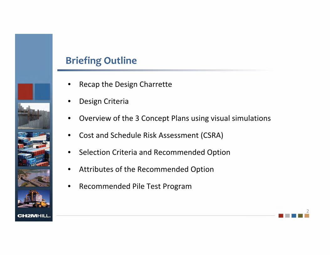
Briefing Outline
2
• Recap the Design Charrette
• Design Criteria
• Overview of the 3 Concept Plans using visual simulations
• Cost and Schedule Risk Assessment (CSRA)
• Selection Criteria and Recommended Option
• Attributes of the Recommended Option
• Recommended Pile Test Program

September 1, 2011
3
Design CharretteDesign Charrette
Port of Anchorage Intermodal Expansion Project Concept Design Study
March 19, 2013

Charrette Goals for the POA
4
• Provide adequate facilities at POA to support local commerce
and the National Strategic Military Transport
• Provide modern, safe and efficient facilities
• Expand and maintain existing port property
• Encourage natural resource exports and attract new business
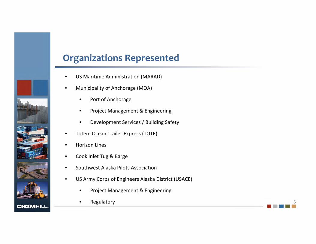
Organizations Represented
5
• US Maritime Administration (MARAD)
• Municipality of Anchorage (MOA)
• Port of Anchorage
• Project Management & Engineering
• Development Services / Building Safety
• Totem Ocean Trailer Express (TOTE)
• Horizon Lines
• Cook Inlet Tug & Barge
• Southwest Alaska Pilots Association
• US Army Corps of Engineers Alaska District (USACE)
• Project Management & Engineering
• Regulatory

Option 1 – Charrette
6

Option 2 – Charrette
7

Option 3 – Charrette
8

Option 4 – Charrette
9

Option 5– Charrette
10
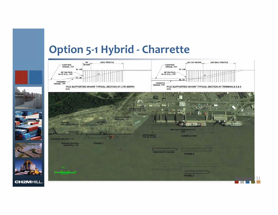
Option 5‐1 Hybrid ‐ Charrette
11
Charrette Direction
12
• Option 1 should be carried forward
• Option 2 wasted too much backlands and should be dropped
• Options 3 and 4 were dropped for several reasons:
• Pushing further offshore is outside the permit area
• Pushing further offshore creates more challenges for vessel
approach and mooring
• Pushing further offshore exacerbates shoaling at Terminal 3
• Option 5 should be carried forward (popular with carriers)
• Option 5 – 1 Hybrid should be developed further
September 1, 2011
13
Design CriteriaDesign Criteria
Port of Anchorage Intermodal Expansion Project Concept Design Study
March 19, 2013

Design Criteria for 15% Concept Design
• Overall – Meet Project Goals– Provide adequate facilities to support
transportation needs of POA• State and local commerce• National strategic transport mission
– Provide modern, safe, and efficient port– Expand and maintain existing properties, facilities,
and equipment to meet expected growth– Encourage natural resource exports and create
employment opportunities
14

Review of Wharf Design Criteria
• Design codes and references – update to include MOTEMS, AASHTO, ASCE 7‐10, etc.
• Facility design requirements– Service life
• 75 years for wharf and trestle• 20 years for pavements and fenders • 50 years for buildings
– Design live loads• 1,000 psf • AASHTO HS25 trucks• 275‐ton mobile crane• 40‐ton top pick & 100‐ton fork lift• 100 gauge rail
15
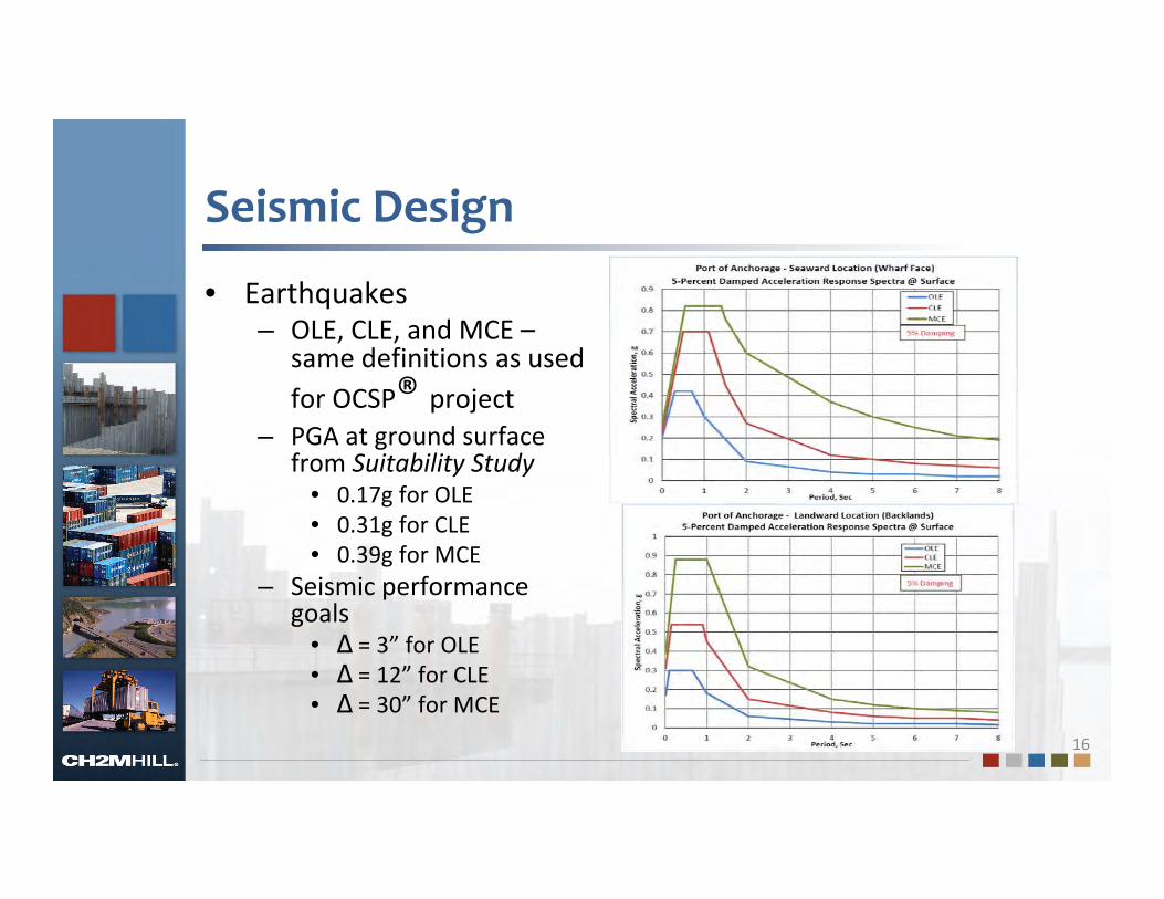
Seismic Design
• Earthquakes– OLE, CLE, and MCE –
same definitions as used for OCSP® project
– PGA at ground surface from Suitability Study
• 0.17g for OLE• 0.31g for CLE• 0.39g for MCE
– Seismic performance goals
• Δ = 3” for OLE• Δ = 12” for CLE• Δ = 30” for MCE
16

Other Environmental Loads
• Tidal– Highest: +34.6 feet MLLW– Lowest: ‐6.4 feet MLLW– Seismic: +7.5 feet MLLW
• Wind– 45 mph operating– 70 mph max speed for mooring – 100 mph max non‐operating
• Mooring loads from vessels– MOTEMS– 150‐ton bollards
• Ice– 24” with 300 psi crush strength– Ice dead load for pile design (8’ diameter) 17

Foundation Design for 15% Concept
• Geotechnical design checks– Embankment stability – Axial and lateral pile capacity– Pile drivability
• Methodologies and tools– SLIDE for stability with transient seepage analyses– APILE for axial capacity and displacement; LPILE for lateral– GRLWEAP for drivability
• Site & groundwater conditions– See Suitability Study for North Extension– Existing terminal from PND/GeoEngineer/Terracon explorations
for South Replacement area – Groundwater from recent measurements
18

Geotechnical Conditions
19
Section C, Option 1 (North Expansion Area)
Section C, Option 5‐1 Hybrid (Existing Terminal Area

Embankment Stability for Tidal Flow
• Tidal fluctuation– Typical change over 24‐
hour period– Groundwater = 20 feet
MLLW in backlands (approx 500 feet from pierhead)
• Effects on stability– Large fluctuation in
seepage gradient– Modeled in SLIDE as
transient flow– Required FS = 1.5 against
piping at embankment– Needed 5 feet of armor
rock to control 20
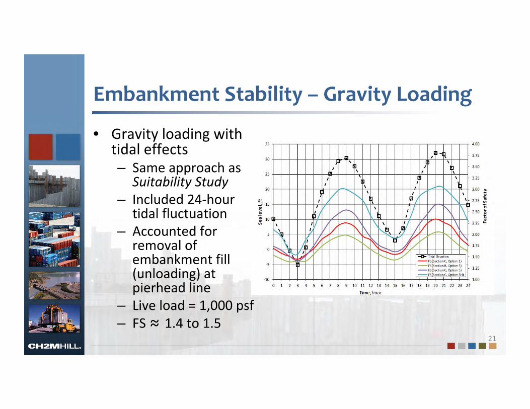
Embankment Stability – Gravity Loading
• Gravity loading with tidal effects– Same approach as
Suitability Study– Included 24‐hour
tidal fluctuation– Accounted for
removal of embankment fill (unloading) at pierhead line
– Live load = 1,000 psf– FS ≈ 1.4 to 1.5
21

Embankment Stability – Seismic Loading
• Pseudo‐static method– No cyclic degradation in BCF (implies small movements)– Kh = 0.5*PGA at ground surface– Undrained response in Estuarine Deposits with reduced Su/σ’v– Porewater buildup in loose granular soil and common fill
22
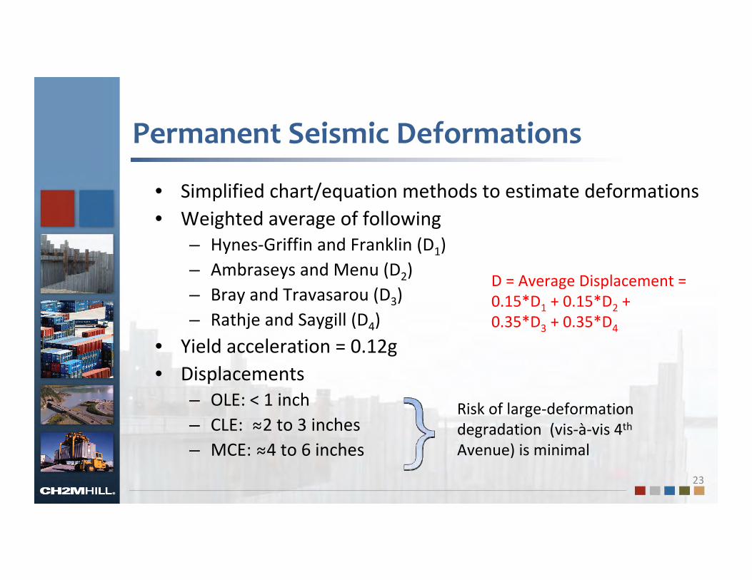
Permanent Seismic Deformations
• Simplified chart/equation methods to estimate deformations• Weighted average of following
– Hynes‐Griffin and Franklin (D1)– Ambraseys and Menu (D2)– Bray and Travasarou (D3)– Rathje and Saygill (D4)
• Yield acceleration = 0.12g• Displacements
– OLE: < 1 inch– CLE: ≈2 to 3 inches– MCE: ≈4 to 6 inches
23
D = Average Displacement =0.15*D1 + 0.15*D2 + 0.35*D3 + 0.35*D4
Risk of large‐deformation degradation (vis‐à‐vis 4th
Avenue) is minimal
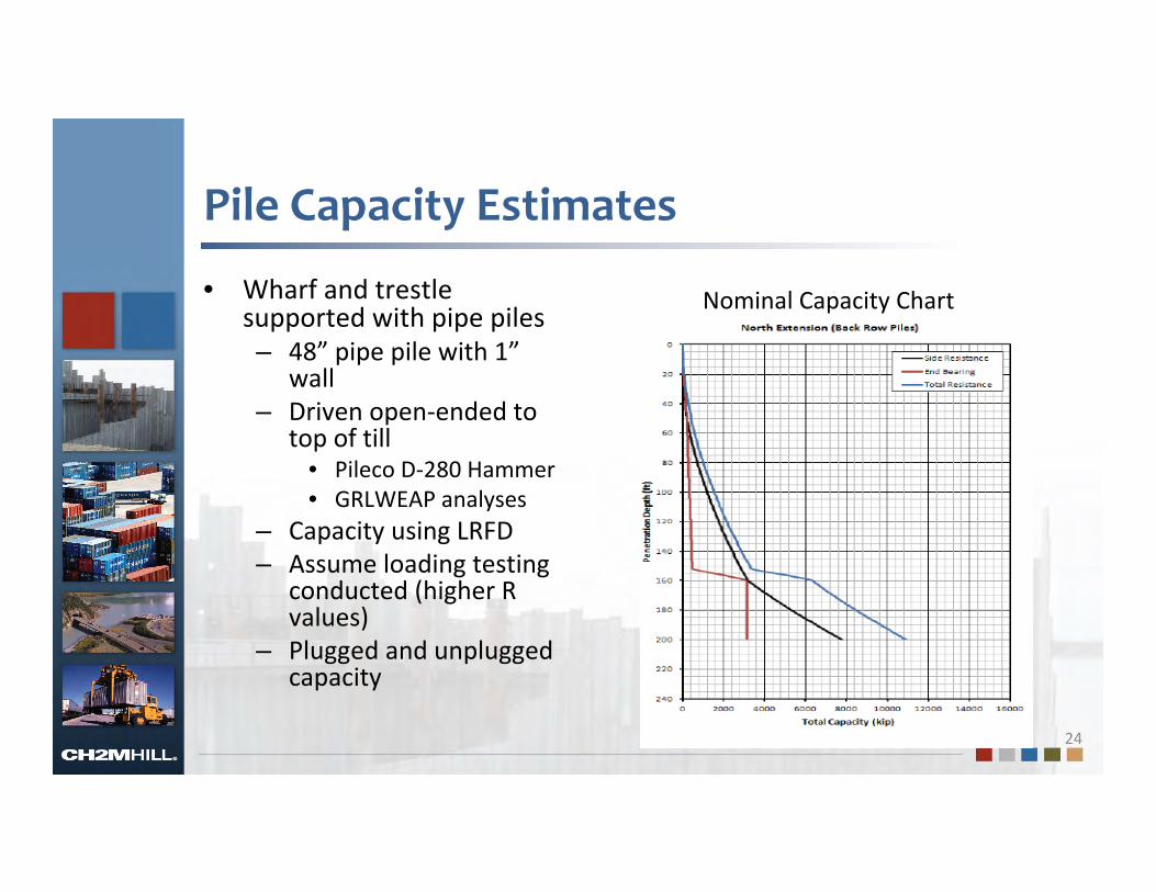
Pile Capacity Estimates
• Wharf and trestle supported with pipe piles– 48” pipe pile with 1”
wall– Driven open‐ended to
top of till• Pileco D‐280 Hammer• GRLWEAP analyses
– Capacity using LRFD– Assume loading testing
conducted (higher R values)
– Plugged and unplugged capacity
24
Nominal Capacity Chart

Future Foundation Design Work
• Design Considerations– Refinement of transient seepage analyses– SSI studies for wharf embankment using 2D FE/FD methods– Liquefaction potential next to piles and bulkhead– Embankment slope protection for seepage– Retaining wall alternatives (anchored vs cellular vs OCSP® )– Early pile‐load testing (load and indicator piles with PDA)
• Construction– Effects of OCSP® demo and granular fill removal– Cellular bulkhead design– Micropile design
25

September 1, 2011
26
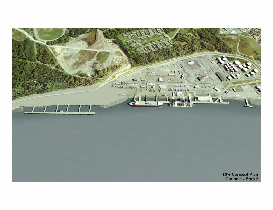
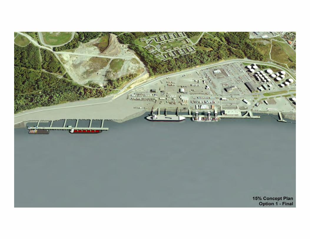
Option 1 ‐ VisualizationsOption 1 ‐ Visualizations
Port of Anchorage Intermodal Expansion Project Concept Design Study
March 19, 2013

27

28
29
30

31
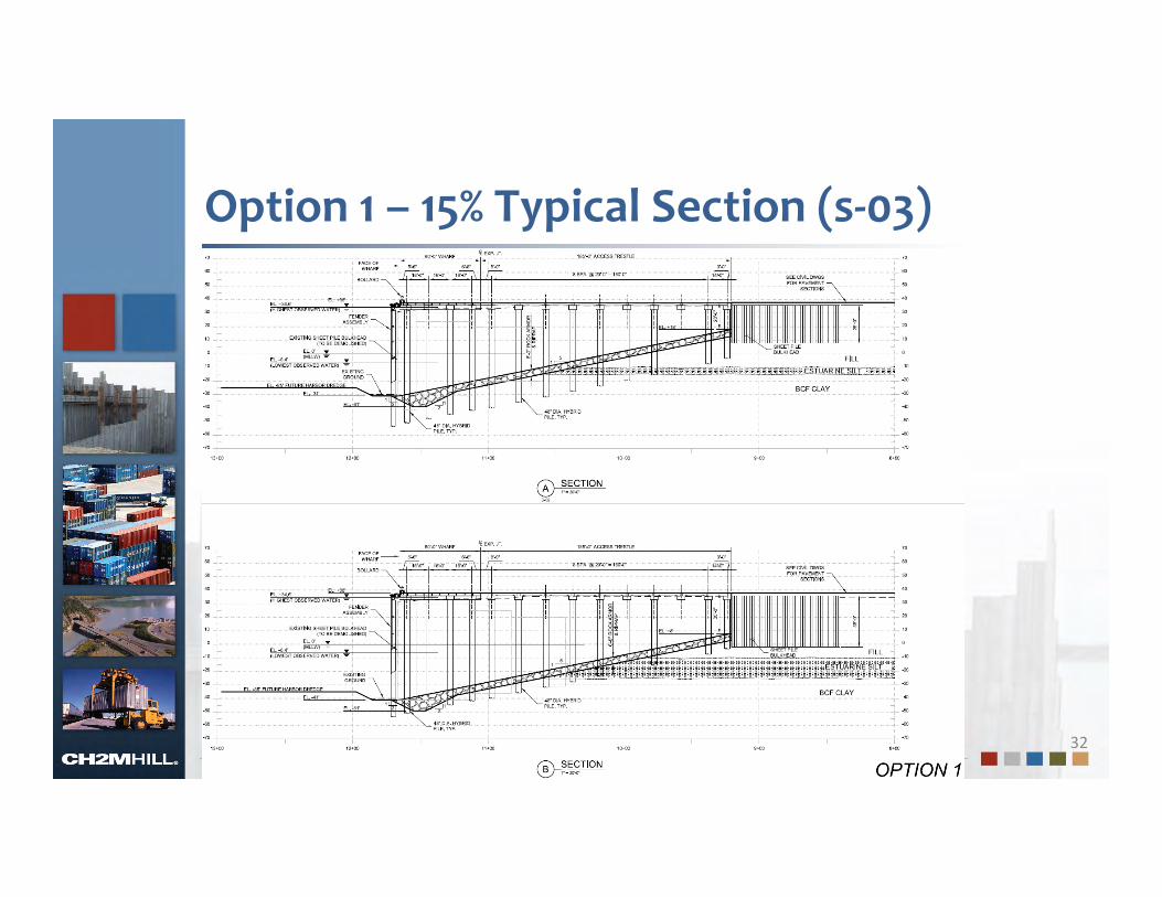
Option 1 – 15% Typical Section (s‐03)
32

Option 1 – 15% Typical Sections (s‐04)
33

Hybrid Reinforced Concrete Piling
34
September 1, 2011
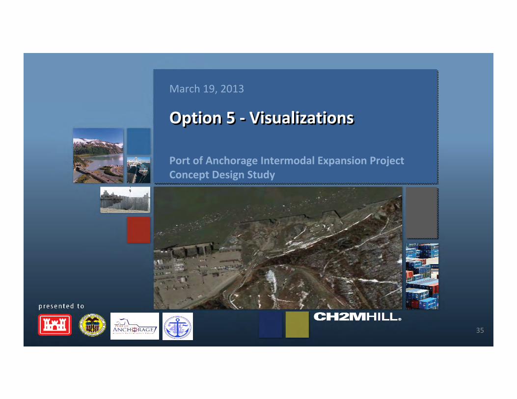
35
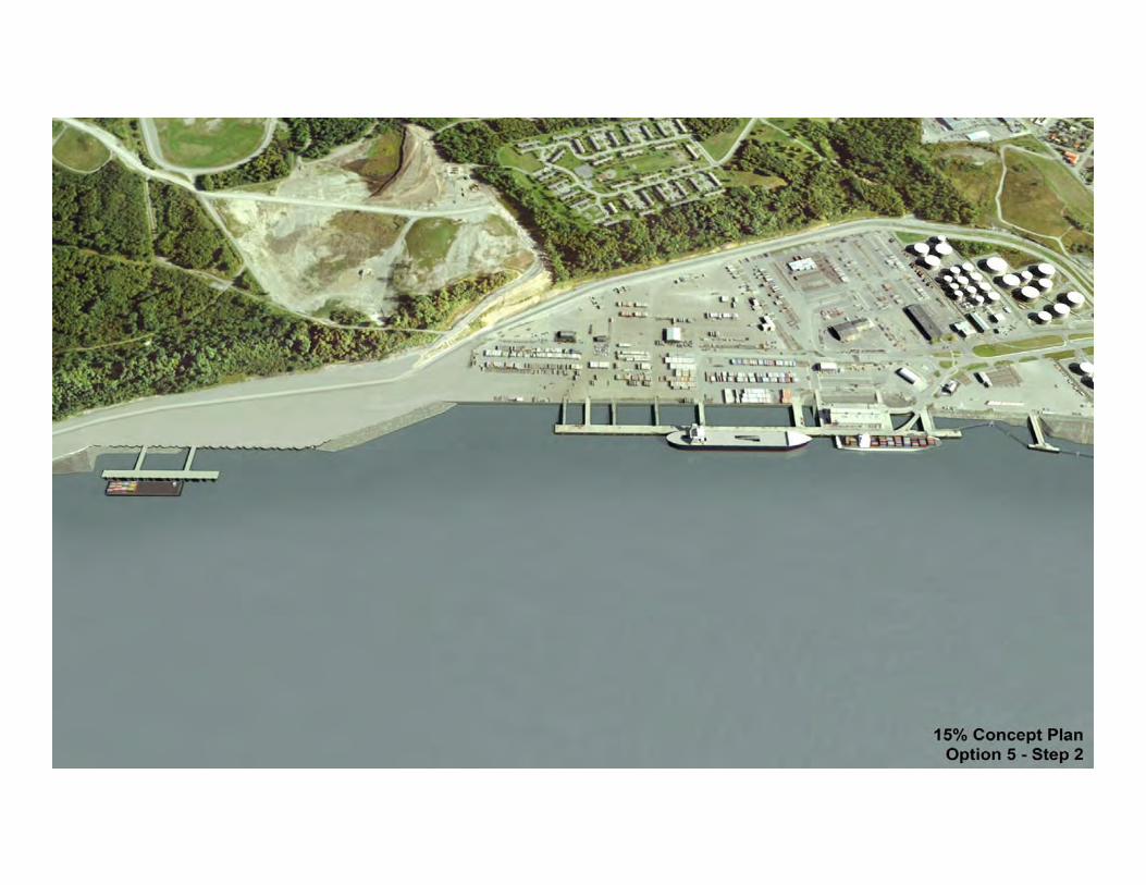
Option 5 ‐ VisualizationsOption 5 ‐ Visualizations
Port of Anchorage Intermodal Expansion Project Concept Design Study
March 19, 2013

36

37
38

39

40

41

42

43

Option 5 – 15% Typical Sections (s‐03)
44

Option 5 – 15% Typical Sections (s‐04)
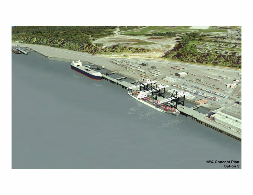
45
September 1, 2011
46
Option 5‐1 Hybrid ‐ VisualizationsOption 5‐1 Hybrid ‐ Visualizations
Port of Anchorage Intermodal Expansion Project Concept Design Study
March 19, 2013

47

48

49

50

51

52

53
54

Option 5‐1 Hybrid – 15% Typical Section (s‐03)
55
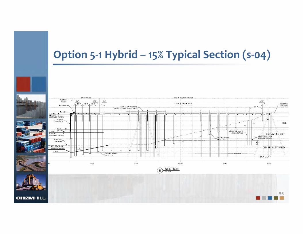
Option 5‐1 Hybrid – 15% Typical Section (s‐04)
56

Option 5‐1 Hybrid – 15% Typical Section (s‐04)
57

September 1, 2011
58
Cost and Schedule Risk
Assessment (CSRA)
Cost and Schedule Risk
Assessment (CSRA)Port of Anchorage Intermodal Expansion Project Concept Design Study
March 19, 2013

Cost and Schedule Risk Assessment
59
• Typical deterministic method estimates costs then adds contingency (e.g. 20%)
• Benefits of the CSRA– Identifies high risk items to cost and schedule
– Provides leadership contingency information for scheduling and budgeting
– Allows management of risks through a formal process throughout the design process.
– Provides a proven structure for communicating project costs with stakeholders.

Cost Estimates
60% Confidence 80% Confidence 100% Confidence
Option 1 $363M $377M $447M
Option 5 $618M $642M $763M
Option 5‐1 Hybrid $582M $602M $735M
60
Notes:1.All options assume construction start 2015, with construction midpoint 20172.All options use surplus sheet piling3.All berths designed to MCE level earthquake

61
62

63

September 1, 2011
64
Selection Criteria and Scoring Selection Criteria and Scoring
Port of Anchorage Intermodal Expansion Project Concept Design Study
March 19, 2013

Qualitative Scoring Factors
• The evaluation team consisted of members from the POA, MARAD, MOA, USACE, and CH2M HILL.
– 1.0 Outstanding
– 0.8 Excellent
– 0.6 Good
– 0.4 Fair
– 0.2 Poor
– 0.0 Unsatisfactory
65

Selection Criteria and Recommended Option
66

September 1, 2011
67
Recommended Option AttributesRecommended Option Attributes
Port of Anchorage Intermodal Expansion Project Concept Design Study
March 19, 2013
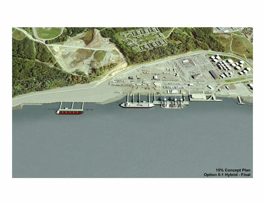
Option 5‐1 Hybrid Attributes
68
• Has the lowest initial investment cost
• Phase 1 $327M (North End Hybrid Berth)
• Phase 2 $275M (Terminal 2 and 3)
• Total $602M
• Hybrid Berth serves both barge and deep draft customers
• Retains most backlands at North End (32 acres)
• Allows for expansion to the south in the future
• Less maintenance dredging anticipated
• Improved vessel approach

69

70

September 1, 2011
71
Recommended Pile Test ProgramRecommended Pile Test Program
Port of Anchorage Intermodal Expansion Project Concept Design Study
March 19, 2013

Pile‐Load Testing• Objectives
– Evaluate installation methods
– Determine capacity & load displacement
– Assess plug development and setup
• Scope– 1 to 2 top down capacity
tests• Fully instrumented• Follow ASTM D 1143
– Indicator pile tests• Pile installation• 10 to 15 • Noise and vibrations 72
Key Considerations for Pile‐Load Test
• Testing Questions – Conduct behind existing OCSP ®
before removal• Overburden effects• Noise and vibrations
– Tests at both existing terminal and in North Extension
– What pile diameter• Full diameter at higher costs ‐
‐ BEST• Smaller diameter and use unit
side friction and toe resistance for design
– How to develop reaction => probably reaction piles and kentledge
• Interpretation of Results– Does pile need to be driven to
till to meet capacity requirements
• Function as friction pile• Settlement
– How does plug function during driving
• Need for driving shoe• Long‐term setup• Plugged vs unplugged
capacity– What is optimum driving
method• Size of hammer• Driving stresses
73

September 1, 2011
74
QuestionsQuestions
Port of Anchorage Intermodal Expansion Project Concept Design Study
March 19, 2013