Embed Size (px)
Citation preview
GA-945GM-S2 /GA-945GM-DS2 /GA-945GMF-DS2Intel® CoreTM 2 Extreme dual-core / CoreTM 2 DuoIntel® Pentium® D / Pentium® 4 / Celeron® D LGA775 Processor Motherboard
User's ManualRev. 390112ME-945GMFDR-3901R
* The WEEE marking on the product indicates this product must not be disposed of with user's other household wasteand must be handed over to a designated collection point for the recycling of waste electrical and electronic equipment!!
* The WEEE marking applies only in European Union's member states.

Motherboard
GA-945GM-DS2/GA-945GMF-DS2
Nov. 10, 2006
Nov. 10, 2006 Motherboard
GA-945GM-DS2/GA-945GM
F-DS2

Motherboard
GA-945GM-S2
Jul. 7, 2006
Jul. 7, 2006 Motherboard
GA-945GM-S2

Copyright© 2007 GIGA-BYTE TECHNOLOGY CO., LTD. All rights reserved.The trademarks mentioned in the manual are legally registered to their respective companies.
NoticeThe written content provided with this product is the property of Gigabyte.No part of this manual may be reproduced, copied, translated, or transmitted in any form or by anymeans without Gigabyte's prior written permission. Specifications and features are subject tochange without prior notice.
Product Manual ClassificationIn order to assist in the use of this product, Gigabyte has categorized the user manual in thefollowing:
For detailed product information and specifications, please carefully read the "Product User Manual".
For detailed information related to Gigabyte's unique features, please go to "TechnologyGuide" section on Gigabyte's website to read or download the information you need.
For more product details, please click onto Gigabyte's website at www.gigabyte.com.tw
- 5 -
Table of Contents
Item Checklist ................................................................................................................. 7Optional Accessories ...................................................................................................... 7GA-945GM-S2/GA-945GM-DS2/GA-945GMF-DS2 Motherboard Layout ...................... 8Block Diagram ................................................................................................................ 9
Chapter 1 Hardware Installation ....................................................................................111-1 Considerations Prior to Installation ................................................................... 111-2 Feature Summary .......................................................................................... 121-3 Installation of the CPU and CPU Cooler ....................................................... 14
1-3-1 Installation of the CPU ......................................................................................... 141-3-2 Installation of the CPU Cooler ............................................................................ 15
1-4 Installation of Memory .................................................................................... 161-5 Installation of Expansion Cards ...................................................................... 181-6 I/O Back Panel Introduction ........................................................................... 191-7 Connectors Introduction .................................................................................. 20
Chapter 2 BIOS Setup ................................................................................................ 31The Main Menu (For example: GA-945GMF-DS2 BIOS Ver. : F1a) ........................ 322-1 Standard CMOS Features ............................................................................. 342-2 Advanced BIOS Features .............................................................................. 362-3 Integrated Peripherals ..................................................................................... 382-4 Power Management Setup ............................................................................. 422-5 PnP/PCI Configurations ................................................................................. 442-6 PC Health Status ........................................................................................... 452-7 Frequency/Voltage Control ............................................................................. 472-8 Load Fail-Safe Defaults ................................................................................... 482-9 Load Optimized Defaults ................................................................................. 482-10 Set Supervisor/User Password ..................................................................... 492-11 Save & Exit Setup ......................................................................................... 502-12 Exit Without Saving ....................................................................................... 50
- 6 -
Chapter 3 Install Drivers ............................................................................................. 513-1 Install Chipset Drivers .................................................................................... 513-2 Software Applications ..................................................................................... 523-3 Driver CD Information .................................................................................... 523-4 Hardware Information ..................................................................................... 533-5 Contact Us ..................................................................................................... 53
Chapter 4 Appendix ................................................................................................... 554-1 Unique Software Utilities ................................................................................ 55
4-1-1 EasyTune 5 Introduction ..................................................................................... 554-1-2 Xpress Recovery2 Introduction ......................................................................... 564-1-3 Flash BIOS Method Introduction ........................................................................ 584-1-4 2- / 4- / 6- / 8- Channel Audio Function Introduction ...................................... 67
4-2 Troubleshooting ............................................................................................... 72
- 7 -
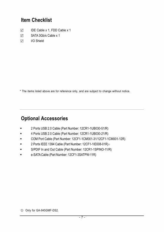
Item ChecklistIDE Cable x 1, FDD Cable x 1SATA 3Gb/s Cable x 1I/O Shield
* The items listed above are for reference only, and are subject to change without notice.
Optional Accessories2 Ports USB 2.0 Cable (Part Number: 12CR1-1UB030-51/R)4 Ports USB 2.0 Cable (Part Number: 12CR1-1UB030-21/R)COM Port Cable (Part Number: 12CF1-1CM001-31/12CF1-1CM001-12R)2 Ports IEEE 1394 Cable (Part Number: 12CF1-1IE008-01R)S/PDIF In and Out Cable (Part Number: 12CR1-1SPINO-11/R)e-SATA Cable (Part Number: 12CF1-3SATPW-11R)
Only for GA-945GMF-DS2.
- 8 -
KB_MS
CD_IN
F_AU
DIO
PCIE_16
CODECSPDIF_IO
PCI1
PCI2
BATTERY
RTL8111B
ATX_12V
USB
LAN
AUDIO
LPT
USB
COMA
PCIE_1
VGA
LGA775
SYS_FAN
CLR_CMOS
1394
CPU_FAN
ATX
FDD
IDE
DDRI
I1
DDRI
I2
DDRI
I3
DDRI
I4
IT87
18
Intel® 945G
F1_1394 F2_1394
BIOS
COMB
F_US
B1
SATA
II0
F_PANEL
Intel® ICH7
PWR_
LED
F_US
B2
SATA
II1
SATA
II2
SATA
II3
CITSB43AB23
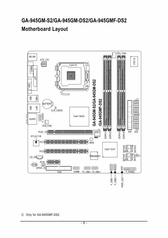
GA-945GM-S2/GA-945GM-DS2/GA-945GMF-DS2Motherboard Layout
Only for GA-945GMF-DS2.
GA-9
45GM
-S2/G
A-94
5GM-
DS2
/GA-
945G
MF-D
S2
- 9 -
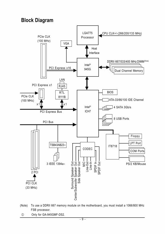
Block Diagram
(Note) To use a DDRII 667 memory module on the motherboard, you must install a 1066/800 MHzFSB processor.
LGA775Processor
HostInterface
Intel®945G
DDRII 667/533/400 MHz DIMM(Note)
Intel®ICH7
BIOS
2 PCI
PCI Bus
PCI Express x1
PCI Express Bus
Dual Channel Memory
PCIe CLK(100 MHz)
4 SATA 3Gb/sx 1
PCI CLK(33 MHz)
PCIe CLK(100 MHz)
PCI Express x16
8 USB Ports
IT8718
Floppy
PS/2 KB/Mouse
LPT Port
Cent
er/S
ubwo
ofer
Spe
aker
Out
Line-
Out
MIC
Line-
InSP
DIF
InSP
DIF
Out
Side
Spe
aker
Out
Surro
und
Spea
ker O
ut
CODEC COM Ports
RTL8111B
x 1
LAN
RJ45
VGA
CPU CLK+/-(266/200/133 MHz)
ATA-33/66/100 IDE Channel
3 IEEE 1394a
TSB43AB23
Only for GA-945GMF-DS2.

- 10 -
Hardware Installation- 11 -
English1-1 Considerations Prior to InstallationPreparing Your ComputerThe motherboard contains numerous delicate electronic circuits and components which can becomedamaged as a result of electrostatic discharge (ESD). Thus, prior to installation, please follow theinstructions below:1. Please turn off the computer and unplug its power cord.2. When handling the motherboard, avoid touching any metal leads or connectors.3. It is best to wear an electrostatic discharge (ESD) cuff when handling electronic components
(CPU, RAM).4. Prior to installing the electronic components, please have these items on top of an antistatic pad or
within a electrostatic shielding container.5. Please verify that the power supply is switched off before unplugging the power supply connector
from the motherboard.
Installation Notices1. Prior to installation, please do not remove the stickers on the motherboard. These stickers are required
for warranty validation.2. Prior to the installation of the motherboard or any hardware, please first carefully read the information
in the provided manual.3. Before using the product, please verify that all cables and power connectors are connected.4. To prevent damage to the motherboard, please do not allow screws to come in contact with the
motherboard circuit or its components.5. Please make sure there are no leftover screws or metal components placed on the motherboard or
within the computer casing.6. Please do not place the computer system on an uneven surface.7. Turning on the computer power during the installation process can lead to damage to system
components as well as physical harm to the user.8. If you are uncertain about any installation steps or have a problem related to the use of the product,
please consult a certified computer technician.
Instances of Non-Warranty1. Damage due to natural disaster, accident or human cause.2. Damage as a result of violating the conditions recommended in the user manual.3. Damage due to improper installation.4. Damage due to use of uncertified components.5. Damage due to use exceeding the permitted parameters.6. Product determined to be an unofficial Gigabyte product.
Chapter 1 Hardware Installation
GA-945GM(F)-(D)S2 Motherboard - 12 -
Engl
ish
1-2 Feature SummaryCPU LGA775 for Intel® CoreTM 2 Extreme dual-core / CoreTM 2 Duo / Pentium® D /
Pentium® 4 / Celeron® DL2 cache varies with CPU
Front Side Bus Supports 1066/800/533 MHz FSBChipset Northbridge: Intel® 945G Express Chipset
Southbridge: Intel® ICH7LAN Onboard Realtek RTL8111B chip (10/100/1000 Mbit)Audio Onboard Realtek ALC888 CODEC chip
Supports High Definition AudioSupports 2 / 4 / 6 / 8 channel audioSupports S/PDIF In/Out connectionSupports CD In connection
IEEE 1394 Onboard T.I. TSB43AB23 chip3 IEEE 1394a ports
Storage Intel® ICH7 Southbrigde- 1 FDD connector, allowing connection of 1 FDD device- 1 IDE connector with ATA-33/66/100 support, allowing connection of 2
IDE devices- 4 SATA 3Gb/s connectors, allowing connection of 4 SATA 3Gb/s
devicesO.S Support Microsoft Windows® 2000/XPMemory 4 DDRII DIMM memory slots (supports up to 4 GB memory) (Note 1)
Supports dual channel DDRII 667/533/400 unbuffered DIMMs (Note 2)
Supports 1.8V DDRII DIMMsExpanstion Slots 1 PCI Express x16 slot
1 PCI Express x1 slot2 PCI slots
Internal Connectors 1 24-pin ATX power connector1 4-pin ATX 12V power connector1 floppy connector1 IDE connector4 SATA 3Gb/s connectors1 CPU fan connector1 system fan connector1 front panel connector1 front audio connector1 CD In connector1 S/PDIF In/Out connector2 USB 2.0/1.1 connectors for additional 4 ports by cables2 IEEE 1394a connectors for additional 2 ports by cables1 COMB connector1 Chassis Intrusion connector1 power LED connector
Only for GA-945GMF-DS2."*" Only the GA-945GM-DS2/GA-945GMF-DS2 adopts All-Solid Capacitor design.
Hardware Installation- 13 -
English
(Note 1) Due to standard PC architecture, a certain amount of memory is reserved for system usageand therefore the actual memory size is less than the stated amount. For example, 4 GB ofmemory size will instead be shown as 3.xx GB memory during system startup.
(Note 2) To use a DDRII 667 memory module on the motherboard, you must install a 1066/800 MHzFSB processor.
(Note 3) EasyTune functions may vary depending on different motherboards.
Rear Panel I/O 1 PS/2 keyboard port1 PS/2 mouse port1 parallel port1 serial port1 VGA port4 USB 2.0/1.1 ports1 IEEE 1394a port1 RJ-45 port6 audio jacks (Line In / Line Out / MIC In/Surround Speaker Out (RearSpeaker Out)/Center/Subwoofer Speaker Out/Side Speaker Out)
I/O Control IT8718 chipHardware Monitor System voltage detection
CPU temperature detectionCPU / System fan speed detectionCPU warning temperatureCPU / System fan failure warningCPU smart fan control
BIOS 1 4 Mbit flash ROMUse of licensed AWARD BIOSPnP 1.0a, DMI 2.0, SM BIOS 2.3, ACPI 1.0b
Additional Features Supports @BIOSSupports Download CenterSupports Q-FlashSupports EasyTune (only supports Hardware Monitor function)(Note 3)
Supports Xpress InstallSupports Xpress Recovery2Supports Xpress BIOS Rescue
Bundle Software Norton Internet Security (OEM revision)Form Factor Micro ATX form factor; 24.4cm x 23.3cm
Only for GA-945GMF-DS2."*" Only the GA-945GM-DS2/GA-945GMF-DS2 adopts All-Solid Capacitor design.
GA-945GM(F)-(D)S2 Motherboard - 14 -
Engl
ish
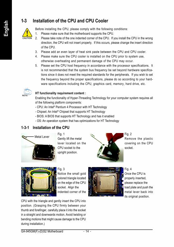
1-3 Installation of the CPU and CPU CoolerBefore installing the CPU, please comply with the following conditions:1. Please make sure that the motherboard supports the CPU.2. Please take note of the one indented corner of the CPU. If you install the CPU in the wrong
direction, the CPU will not insert properly. If this occurs, please change the insert directionof the CPU.
3. Please add an even layer of heat sink paste between the CPU and CPU cooler.4. Please make sure the CPU cooler is installed on the CPU prior to system use,
otherwise overheating and permanent damage of the CPU may occur.5. Please set the CPU host frequency in accordance with the processor specifications. It
is not recommended that the system bus frequency be set beyond hardware specifica-tions since it does not meet the required standards for the peripherals. If you wish to setthe frequency beyond the proper specifications, please do so according to your hard-ware specifications including the CPU, graphics card, memory, hard drive, etc.
HT functionality requirement content :Enabling the functionality of Hyper-Threading Technology for your computer system requires allof the following platform components:- CPU: An Intel® Pentium 4 Processor with HT Technology- Chipset: An Intel® Chipset that supports HT Technology- BIOS: A BIOS that supports HT Technology and has it enabled- OS: An operation system that has optimizations for HT Technology
1-3-1 Installation of the CPUFig. 1Gently lift the metallever located on theCPU socket to theupright position.
Metal LeverFig. 2Remove the plast iccovering on the CPUsocket.
Fig. 3Notice the small goldcolored triangle locatedon the edge of the CPUsocket. Align theindented corner of the
Fig. 4Once the CPU isproperly inserted,please replace theload plate and push themetal lever back intoits original position.
CPU with the triangle and gently insert the CPU intoposition. (Grasping the CPU firmly between yourthumb and forefinger, carefully place it into the socketin a straight and downwards motion. Avoid twisting orbending motions that might cause damage to the CPUduring installation.)
Hardware Installation- 15 -
English
1-3-2 Installation of the CPU Cooler
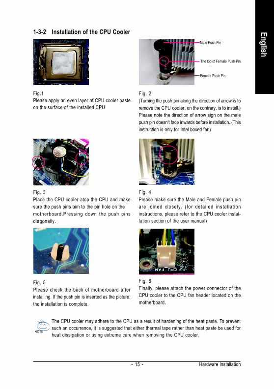
The CPU cooler may adhere to the CPU as a result of hardening of the heat paste. To preventsuch an occurrence, it is suggested that either thermal tape rather than heat paste be used forheat dissipation or using extreme care when removing the CPU cooler.
Fig. 6Finally, please attach the power connector of theCPU cooler to the CPU fan header located on themotherboard.
Fig. 3Place the CPU cooler atop the CPU and makesure the push pins aim to the pin hole on themotherboard.Pressing down the push pinsdiagonally.
Fig. 4Please make sure the Male and Female push pinare jo ined closely. ( for detai led instal lat ioninstructions, please refer to the CPU cooler instal-lation section of the user manual)
Fig. 5Please check the back of motherboard afterinstalling. If the push pin is inserted as the picture,the installation is complete.
Fig.1Please apply an even layer of CPU cooler pasteon the surface of the installed CPU.
Fig. 2(Turning the push pin along the direction of arrow is toremove the CPU cooler, on the contrary, is to install.)Please note the direction of arrow sign on the malepush pin doesn't face inwards before installation. (Thisinstruction is only for Intel boxed fan)
Male Push Pin
Female Push Pin
The top of Female Push Pin
GA-945GM(F)-(D)S2 Motherboard - 16 -
Engl
ish
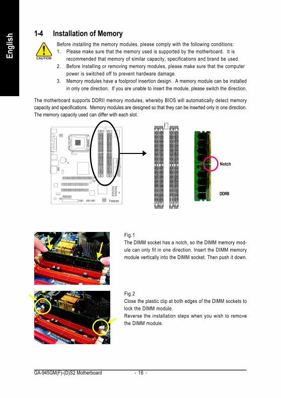
The motherboard supports DDRII memory modules, whereby BIOS will automatically detect memorycapacity and specifications. Memory modules are designed so that they can be inserted only in one direction.The memory capacity used can differ with each slot.
Before installing the memory modules, please comply with the following conditions:1. Please make sure that the memory used is supported by the motherboard. It is
recommended that memory of similar capacity, specifications and brand be used.2. Before installing or removing memory modules, please make sure that the computer
power is switched off to prevent hardware damage.3. Memory modules have a foolproof insertion design. A memory module can be installed
in only one direction. If you are unable to insert the module, please switch the direction.
1-4 Installation of Memory
Notch
DDRII
Fig.1The DIMM socket has a notch, so the DIMM memory mod-ule can only fit in one direction. Insert the DIMM memorymodule vertically into the DIMM socket. Then push it down.
Fig.2Close the plastic clip at both edges of the DIMM sockets tolock the DIMM module.Reverse the installation steps when you wish to removethe DIMM module.

Hardware Installation- 17 -
English
Dual Channel Memory ConfigurationThe GA-945GM-S2/GA-945GM-DS2/GA-945GMF-DS2 supports the DualChannel Technology. After operating the Dual Channel Technology, the band-width of memory bus will double.
The GA-945GM-S2/GA-945GM-DS2/GA-945GMF-DS2 includes 4 DIMM sockets, and each Channelhas two DIMM sockets as following:
Channel 0 : DDRII1, DDRII2Channel 1 : DDRII3, DDRII4
If you want to operate the Dual Channel Technology, please note the following explanations due to thelimitation of Intel chipset specifications.
1. Dual Channel mode will not be enabled if only one DDRII memory module is installed.2. To enable Dual Channel mode with two or four memory modules (it is recommended to use
memory modules of identical brand, size, chips, and speed), you must install them into DIMMsockets of the same color.
The following is a Dual Channel Memory configuration table:(DS: Double Side, SS: Single Side, "--": Empty)
DDR II1 DDR II2 DDR II3 DDR II4DS/SS - - DS/SS - -- - DS/SS - - DS/SSDS/SS DS/SS DS/SS DS/SS
2 memory modules
4 memory modules
GA-945GM(F)-(D)S2 Motherboard - 18 -
Engl
ish
1-5 Installation of Expansion CardsYou can install your expansion card by following the steps outlined below:1. Read the related expansion card's instruction document before install the expansion card into the
computer.2. Remove your computer's chassis cover, screws and slot bracket from the computer.3. Press the expansion card firmly into expansion slot in motherboard.4. Be sure the metal contacts on the card are indeed seated in the slot.5. Replace the screw to secure the slot bracket of the expansion card.6. Replace your computer's chassis cover.7. Power on the computer, if necessary, setup BIOS utility of expansion card from BIOS.8. Install related driver from the operating system.
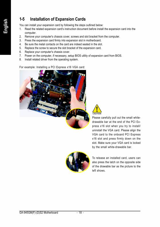
For example: Installing a PCI Express x16 VGA card:
To release an installed card, users canalso press the latch on the opposite sideof the drawable bar as the picture to theleft shows.
Please carefully pull out the small white-drawable bar at the end of the PCI Ex-press x16 slot when you try to install/uninstall the VGA card. Please align theVGA card to the onboard PCI Expressx16 slot and press firmly down on theslot. Make sure your VGA card is lockedby the small white-drawable bar.
Hardware Installation- 19 -
English
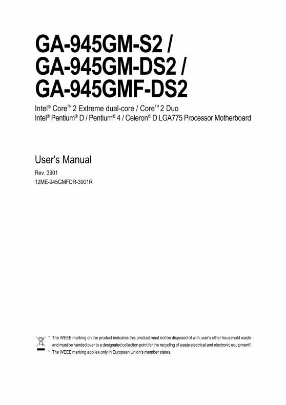
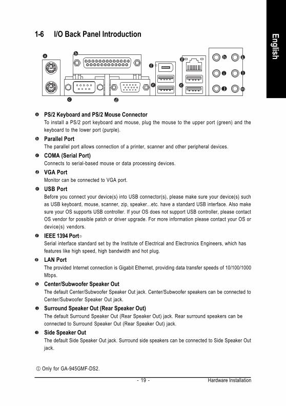
1-6 I/O Back Panel Introduction
PS/2 Keyboard and PS/2 Mouse ConnectorTo install a PS/2 port keyboard and mouse, plug the mouse to the upper port (green) and thekeyboard to the lower port (purple).Parallel PortThe parallel port allows connection of a printer, scanner and other peripheral devices.COMA (Serial Port)Connects to serial-based mouse or data processing devices.VGA PortMonitor can be connected to VGA port.USB PortBefore you connect your device(s) into USB connector(s), please make sure your device(s) suchas USB keyboard, mouse, scanner, zip, speaker...etc. have a standard USB interface. Also makesure your OS supports USB controller. If your OS does not support USB controller, please contactOS vendor for possible patch or driver upgrade. For more information please contact your OS ordevice(s) vendors.IEEE 1394 PortSerial interface standard set by the Institute of Electrical and Electronics Engineers, which hasfeatures like high speed, high bandwidth and hot plug.LAN PortThe provided Internet connection is Gigabit Ethernet, providing data transfer speeds of 10/100/1000Mbps.Center/Subwoofer Speaker OutThe default Center/Subwoofer Speaker Out jack. Center/Subwoofer speakers can be connected toCenter/Subwoofer Speaker Out jack.Surround Speaker Out (Rear Speaker Out)The default Surround Speaker Out (Rear Speaker Out) jack. Rear surround speakers can beconnected to Surround Speaker Out (Rear Speaker Out) jack.Side Speaker OutThe default Side Speaker Out jack. Surround side speakers can be connected to Side Speaker Outjack.
Only for GA-945GMF-DS2.
GA-945GM(F)-(D)S2 Motherboard - 20 -
Engl
ish
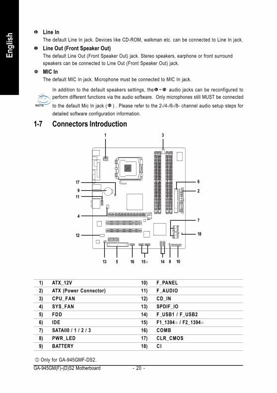
1-7 Connectors Introduction
Line InThe default Line In jack. Devices like CD-ROM, walkman etc. can be connected to Line In jack.Line Out (Front Speaker Out)The default Line Out (Front Speaker Out) jack. Stereo speakers, earphone or front surroundspeakers can be connected to Line Out (Front Speaker Out) jack.MIC InThe default MIC In jack. Microphone must be connected to MIC In jack.
In addition to the default speakers settings, the ~ audio jacks can be reconfigured toperform different functions via the audio software. Only microphones still MUST be connectedto the default Mic In jack ( ) . Please refer to the 2-/4-/6-/8- channel audio setup steps fordetailed software configuration information.
1) ATX_12V2) ATX (Power Connector)3) CPU_FAN4) SYS_FAN5) FDD6) IDE7) SATAII0 / 1 / 2 / 38) PWR_LED9) BATTERY
10) F_PANEL11) F_AUDIO12) CD_IN13) SPDIF_IO14) F_USB1 / F_USB215) F1_1394 / F2_139416) COMB17) CLR_CMOS18) C I
2
1
14
7
18
5
12
15 8
3
10
4
11
6
9
17
13 16
Only for GA-945GMF-DS2.
Hardware Installation- 21 -
English
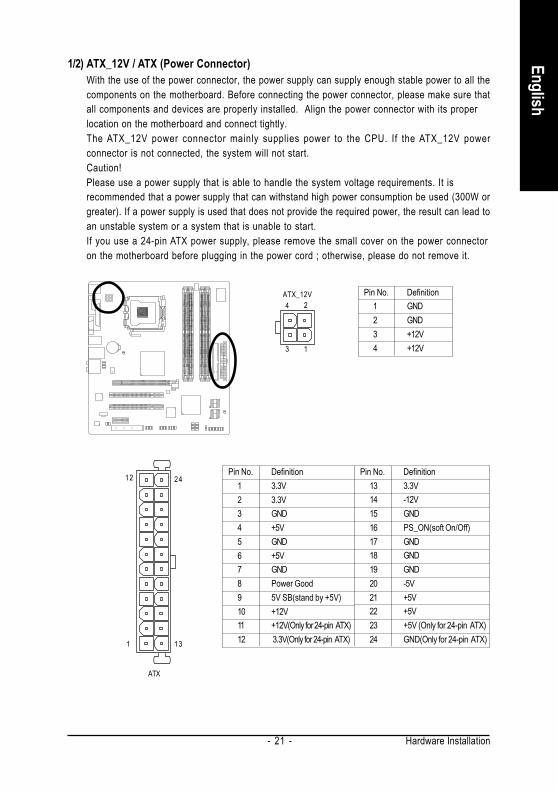
1/2) ATX_12V / ATX (Power Connector)With the use of the power connector, the power supply can supply enough stable power to all thecomponents on the motherboard. Before connecting the power connector, please make sure thatall components and devices are properly installed. Align the power connector with its properlocation on the motherboard and connect tightly.The ATX_12V power connector mainly supplies power to the CPU. If the ATX_12V powerconnector is not connected, the system will not start.Caution!Please use a power supply that is able to handle the system voltage requirements. It isrecommended that a power supply that can withstand high power consumption be used (300W orgreater). If a power supply is used that does not provide the required power, the result can lead toan unstable system or a system that is unable to start.If you use a 24-pin ATX power supply, please remove the small cover on the power connectoron the motherboard before plugging in the power cord ; otherwise, please do not remove it.
131
2412 Pin No. Definition13 3.3V14 -12V15 GND16 PS_ON(soft On/Off)17 GND18 GND19 GND20 -5V21 +5V22 +5V23 +5V (Only for 24-pin ATX)24 GND(Only for 24-pin ATX)
Pin No. Definition1 3.3V2 3.3V3 GND4 +5V5 GND6 +5V7 GND8 Power Good9 5V SB(stand by +5V)10 +12V11 +12V(Only for 24-pin ATX)12 3.3V(Only for 24-pin ATX)
Pin No. Definition1 GND2 GND3 +12V4 +12V13
24ATX_12V
ATX
GA-945GM(F)-(D)S2 Motherboard - 22 -
Engl
ish
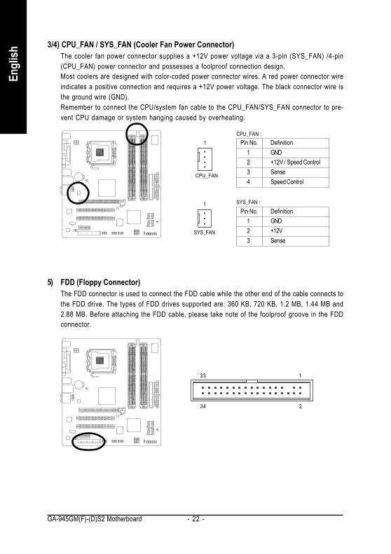
3/4) CPU_FAN / SYS_FAN (Cooler Fan Power Connector)The cooler fan power connector supplies a +12V power voltage via a 3-pin (SYS_FAN) /4-pin(CPU_FAN) power connector and possesses a foolproof connection design.Most coolers are designed with color-coded power connector wires. A red power connector wireindicates a positive connection and requires a +12V power voltage. The black connector wire isthe ground wire (GND).Remember to connect the CPU/system fan cable to the CPU_FAN/SYS_FAN connector to pre-vent CPU damage or system hanging caused by overheating.
1
Pin No. Definition1 GND2 +12V / Speed Control3 Sense4 Speed Control
SYS_FAN
CPU_FAN :
Pin No. Definition1 GND2 +12V3 Sense
SYS_FAN :
5) FDD (Floppy Connector)The FDD connector is used to connect the FDD cable while the other end of the cable connects tothe FDD drive. The types of FDD drives supported are: 360 KB, 720 KB, 1.2 MB, 1.44 MB and2.88 MB. Before attaching the FDD cable, please take note of the foolproof groove in the FDDconnector.
CPU_FAN
1
234
133

Hardware Installation- 23 -
English
6) IDE (IDE Connector)An IDE device connects to the computer via an IDE connector. One IDE connector can connect to oneIDE cable, and the single IDE cable can then connect to two IDE devices (hard drive or optical drive).If you wish to connect two IDE devices, please set the jumper on one IDE device as Master and theother as Slave (for information on settings, please refer to the instructions located on the IDE device).Before attaching the IDE cable, please take note of the foolproof groove in the IDE connector.
7) SATAII0 / 1 / 2 / 3 (SATA 3Gb/s Connector, Controlled by ICH7)SATA 3Gb/s can provide up to 300 MB/s transfer rate. Please refer to the BIOS setting for theSATA 3Gb/s and install the proper driver in order to work properly.
Pin No. Definition1 GND2 TXP3 TXN4 GND5 RXN6 RXP7 GND
2
40
1
39
1
7 1
7
1
7 1
7
SATAII0 SATAII1
SATAII2 SATAII3
GA-945GM(F)-(D)S2 Motherboard - 24 -
Engl
ish
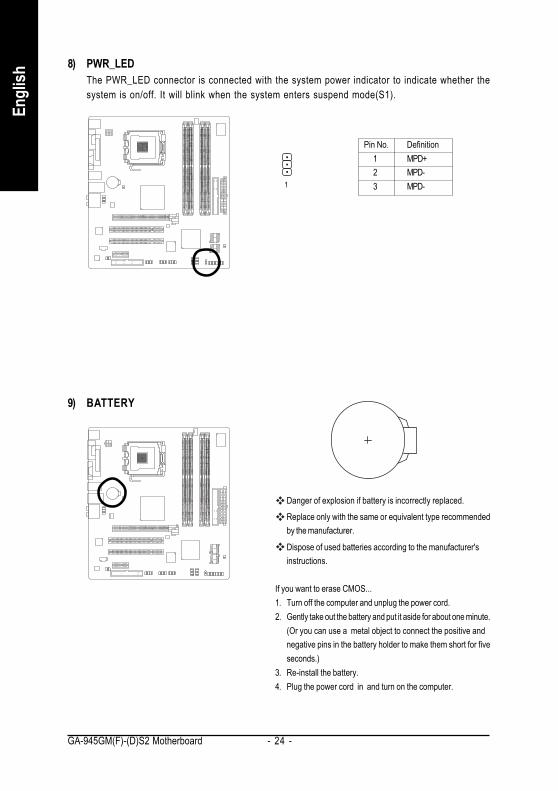
8) PWR_LEDThe PWR_LED connector is connected with the system power indicator to indicate whether thesystem is on/off. It will blink when the system enters suspend mode(S1).
Pin No. Definition1 MPD+2 MPD-3 MPD-1
9) BATTERY
Danger of explosion if battery is incorrectly replaced.
Replace only with the same or equivalent type recommendedby the manufacturer.
Dispose of used batteries according to the manufacturer'sinstructions.
If you want to erase CMOS...1. Turn off the computer and unplug the power cord.2. Gently take out the battery and put it aside for about one minute.
(Or you can use a metal object to connect the positive andnegative pins in the battery holder to make them short for fiveseconds.)
3. Re-install the battery.4. Plug the power cord in and turn on the computer.
Hardware Installation- 25 -
English
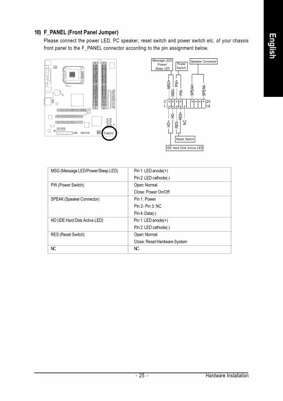
10) F_PANEL (Front Panel Jumper)Please connect the power LED, PC speaker, reset switch and power switch etc. of your chassisfront panel to the F_PANEL connector according to the pin assignment below.
12
1920
HD-
HD+ RE
S+RE
S- NC
IDE Hard Disk Active LED
Reset Switch
SPEA
K-
MSG-
MSG+
PW-
PW+
Message LED/Power/
Sleep LED
Speaker Connector
SPEA
K+
PowerSwitch
MSG (Message LED/Power/Sleep LED) Pin 1: LED anode(+)Pin 2: LED cathode(-)
PW (Power Switch) Open: NormalClose: Power On/Off
SPEAK (Speaker Connector) Pin 1: PowerPin 2- Pin 3: NCPin 4: Data(-)
HD (IDE Hard Disk Active LED) Pin 1: LED anode(+)Pin 2: LED cathode(-)
RES (Reset Switch) Open: NormalClose: Reset Hardware System
NC NC
GA-945GM(F)-(D)S2 Motherboard - 26 -
Engl
ish
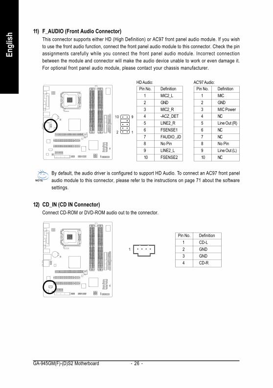
12) CD_IN (CD IN Connector)Connect CD-ROM or DVD-ROM audio out to the connector.
Pin No. Definition1 CD-L2 GND3 GND4 CD-R
1
11) F_AUDIO (Front Audio Connector)This connector supports either HD (High Definition) or AC97 front panel audio module. If you wishto use the front audio function, connect the front panel audio module to this connector. Check the pinassignments carefully while you connect the front panel audio module. Incorrect connectionbetween the module and connector will make the audio device unable to work or even damage it.For optional front panel audio module, please contact your chassis manufacturer.
By default, the audio driver is configured to support HD Audio. To connect an AC97 front panelaudio module to this connector, please refer to the instructions on page 71 about the softwaresettings.
Pin No. Definition1 MIC2 GND3 MIC Power4 NC5 Line Out (R)6 NC7 NC8 No Pin9 Line Out (L)10 NC
AC'97 Audio:Pin No. Definition
1 MIC2_L2 GND3 MIC2_R4 -ACZ_DET5 LINE2_R6 FSENSE17 FAUDIO_JD8 No Pin9 LINE2_L10 FSENSE2
HD Audio:
12
910
Hardware Installation- 27 -
English
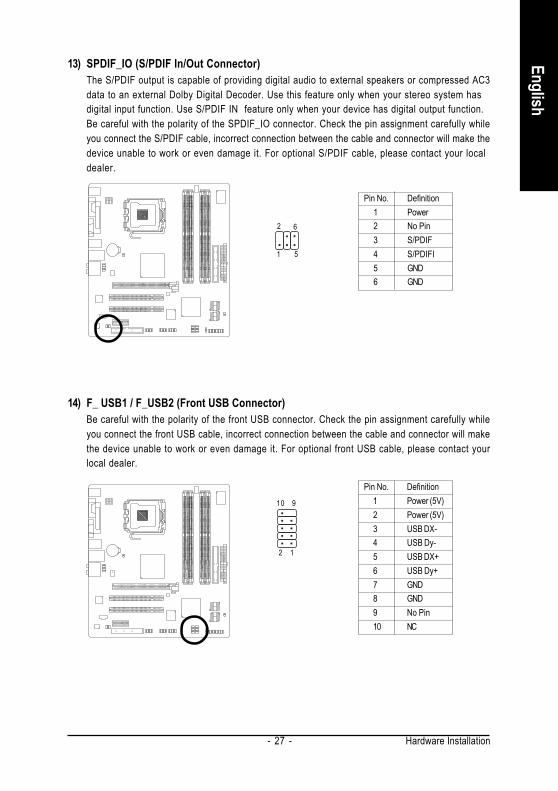
13) SPDIF_IO (S/PDIF In/Out Connector)The S/PDIF output is capable of providing digital audio to external speakers or compressed AC3data to an external Dolby Digital Decoder. Use this feature only when your stereo system hasdigital input function. Use S/PDIF IN feature only when your device has digital output function.Be careful with the polarity of the SPDIF_IO connector. Check the pin assignment carefully whileyou connect the S/PDIF cable, incorrect connection between the cable and connector will make thedevice unable to work or even damage it. For optional S/PDIF cable, please contact your localdealer.
Pin No. Definition1 Power2 No Pin3 S/PDIF4 S/PDIFI5 GND6 GND
1
2
5
6
14) F_ USB1 / F_USB2 (Front USB Connector)Be careful with the polarity of the front USB connector. Check the pin assignment carefully whileyou connect the front USB cable, incorrect connection between the cable and connector will makethe device unable to work or even damage it. For optional front USB cable, please contact yourlocal dealer.
Pin No. Definition1 Power (5V)2 Power (5V)3 USB DX-4 USB Dy-5 USB DX+6 USB Dy+7 GND8 GND9 No Pin10 NC
9
2
10
1
GA-945GM(F)-(D)S2 Motherboard - 28 -
Engl
ish
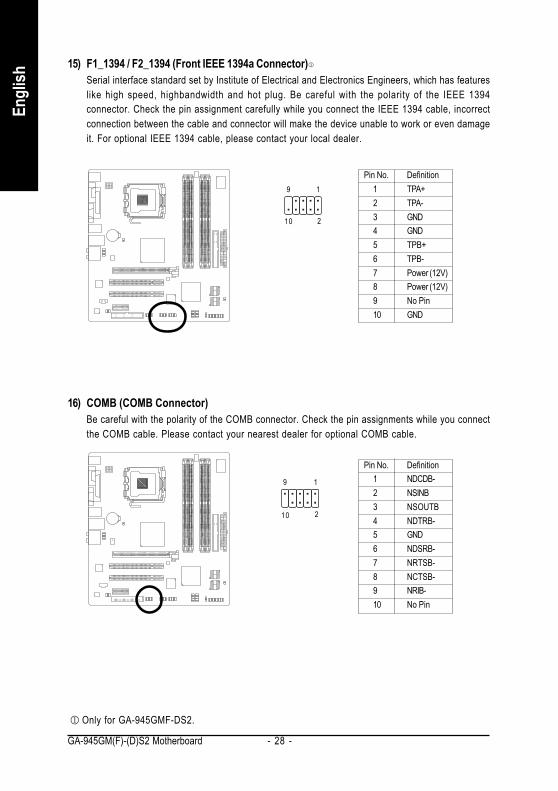
15) F1_1394 / F2_1394 (Front IEEE 1394a Connector)Serial interface standard set by Institute of Electrical and Electronics Engineers, which has featureslike high speed, highbandwidth and hot plug. Be careful with the polarity of the IEEE 1394connector. Check the pin assignment carefully while you connect the IEEE 1394 cable, incorrectconnection between the cable and connector will make the device unable to work or even damageit. For optional IEEE 1394 cable, please contact your local dealer.
Pin No. Definition1 TPA+2 TPA-3 GND4 GND5 TPB+6 TPB-7 Power (12V)8 Power (12V)9 No Pin10 GND
19
210
16) COMB (COMB Connector)Be careful with the polarity of the COMB connector. Check the pin assignments while you connectthe COMB cable. Please contact your nearest dealer for optional COMB cable.
Pin No. Definition1 NDCDB-2 NSINB3 NSOUTB4 NDTRB-5 GND6 NDSRB-7 NRTSB-8 NCTSB-9 NRIB-10 No Pin
10
9
2
1
Only for GA-945GMF-DS2.
Hardware Installation- 29 -
English
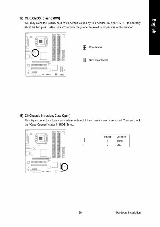
Open: Normal
Short: Clear CMOS
17) CLR_CMOS (Clear CMOS)You may clear the CMOS data to its default values by this header. To clear CMOS, temporarilyshort the two pins. Default doesn't include the jumper to avoid improper use of this header.
18) CI (Chassis Intrusion, Case Open)This 2-pin connector allows your system to detect if the chassis cover is removed. You can checkthe "Case Opened" status in BIOS Setup.
1
Pin No. Definition1 Signal2 GND

GA-945GM(F)-(D)S2 Motherboard - 30 -
Engl
ish
BIOS Setup- 31 -
EnglishBIOS (Basic Input and Output System) includes a CMOS SETUP utility which allows user to configurerequired settings or to activate certain system features.The CMOS SETUP saves the configuration in the CMOS SRAM of the motherboard.When the power is turned off, the battery on the motherboard supplies the necessary power to the CMOSSRAM.When the power is turned on, press the <Del> button during the BIOS POST (Power-On Self Test) willtake you to the CMOS SETUP screen. You can enter the BIOS setup screen by pressing "Ctrl + F1".If you wish to upgrade to a new BIOS, either GIGABYTE's Q-Flash or @BIOS utility can be used.Q-Flash allows the user to quickly and easily update or backup BIOS without entering the operatingsystem.@BIOS is a Windows-based utility that does not require users to boot to DOS before upgrading BIOS butdirectly download and update BIOS from the Internet.
Main MenuThe on-line description of the highlighted setup function is displayed at the bottom of the screen.Status Page Setup Menu / Option Page Setup MenuPress <F1> to pop up a small help window that describes the appropriate keys to use and the possibleselections for the highlighted item. To exit the Help Window press <Esc>.
Chapter 2 BIOS Setup
Because BIOS flashing is potentially risky, please do it with caution and avoid inadequateoperation that may result in system malfunction.
CONTROL KEYS< >< >< >< > Move to select item<Enter> Select Item<Esc> Main Menu - Quit and not save changes into CMOS Status Page Setup Menu
and Option Page Setup Menu - Exit current page and return to Main Menu<Page Up> Increase the numeric value or make changes<Page Down> Decrease the numeric value or make changes<F1> General help, only for Status Page Setup Menu and Option Page Setup Menu<F2> Item Help<F5> Restore the previous CMOS value from CMOS, only for Option Page Setup
Menu<F6> Load the Fail-safe default CMOS value from BIOS default table<F7> Load the Optimized Defaults<F8> Q-Flash utility<F9> System Information<F10> Save all the CMOS changes, only for Main Menu
GA-945GM(F)-(D)S2 Motherboard - 32 -
Engl
ish
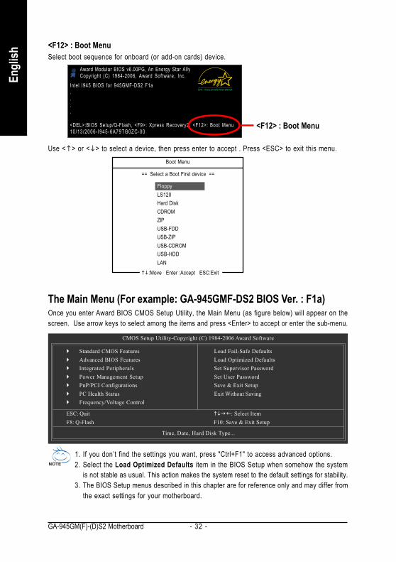
<F12> : Boot Menu
Award Modular BIOS v6.00PG, An Energy Star AllyCopyright (C) 1984-2006, Award Software, Inc.
Intel I945 BIOS for 945GMF-DS2 F1a....
<DEL>:BIOS Setup/Q-Flash, <F9>: Xpress Recovery2, <F12>: Boot Menu10/13 /2006- I945-6A79TG0ZC-00
<F12> : Boot MenuSelect boot sequence for onboard (or add-on cards) device.
Use < > or < > to select a device, then press enter to accept . Press <ESC> to exit this menu.Boot Menu
FloppyLS120Hard DiskCDROMZIPUSB-FDDUSB-ZIPUSB-CDROMUSB-HDDLAN
== Select a Boot First device ==
:Move Enter :Accept ESC:Exit
The Main Menu (For example: GA-945GMF-DS2 BIOS Ver. : F1a)Once you enter Award BIOS CMOS Setup Utility, the Main Menu (as figure below) will appear on thescreen. Use arrow keys to select among the items and press <Enter> to accept or enter the sub-menu.
CMOS Setup Utility-Copyright (C) 1984-2006 Award Software
Standard CMOS FeaturesAdvanced BIOS FeaturesIntegrated PeripheralsPower Management SetupPnP/PCI ConfigurationsPC Health StatusFrequency/Voltage Control
Load Fail-Safe DefaultsLoad Optimized DefaultsSet Supervisor PasswordSet User PasswordSave & Exit SetupExit Without Saving
ESC: Quit : Select ItemF8: Q-Flash F10: Save & Exit Setup
Time, Date, Hard Disk Type...
1. If you don’t find the settings you want, press "Ctrl+F1" to access advanced options.2. Select the Load Optimized Defaults item in the BIOS Setup when somehow the system
is not stable as usual. This action makes the system reset to the default settings for stability.3. The BIOS Setup menus described in this chapter are for reference only and may differ from
the exact settings for your motherboard.
BIOS Setup- 33 -
English
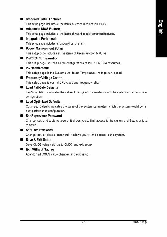
Standard CMOS FeaturesThis setup page includes all the items in standard compatible BIOS.Advanced BIOS FeaturesThis setup page includes all the items of Award special enhanced features.Integrated PeripheralsThis setup page includes all onboard peripherals.Power Management SetupThis setup page includes all the items of Green function features.PnP/PCI ConfigurationThis setup page includes all the configurations of PCI & PnP ISA resources.PC Health StatusThis setup page is the System auto detect Temperature, voltage, fan, speed.Frequency/Voltage ControlThis setup page is control CPU clock and frequency ratio.Load Fail-Safe DefaultsFail-Safe Defaults indicates the value of the system parameters which the system would be in safeconfiguration.Load Optimized DefaultsOptimized Defaults indicates the value of the system parameters which the system would be inbest performance configuration.Set Supervisor PasswordChange, set, or disable password. It allows you to limit access to the system and Setup, or justto Setup.Set User PasswordChange, set, or disable password. It allows you to limit access to the system.Save & Exit SetupSave CMOS value settings to CMOS and exit setup.Exit Without SavingAbandon all CMOS value changes and exit setup.

GA-945GM(F)-(D)S2 Motherboard - 34 -
Engl
ish
2-1 Standard CMOS Features
DateThe date format is <week>, <month>, <day>, <year>.
Week The week, from Sun to Sat, determined by the BIOS and is display-onlyMonth The month, Jan. Through Dec.Day The day, from 1 to 31 (or the maximum allowed in the month)Year The year, from 1999 through 2098
TimeThe times format in <hour> <minute> <second>. The time is calculated base on the 24-hour military-time clock. For example, 1 p.m. is 13:00:00.IDE Channel 0 Master/Slave
IDE HDD Auto-Detection Press "Enter" to select this option for automatic device detection.IDE Channel 0 Master/Slave
IDE devices setup. You can use one of three methods:• Auto Allows BIOS to automatically detect IDE/SATA devices during POST. (Default
value)• None Select this if no IDE/SATA devices are used and the system will skip the
automatic detection step and allow for faster system start up.• Manual User can manually input the correct settings.
Access Mode Use this to set the access mode for the hard drive. The four options are:CHS/LBA/Large/Auto(default:Auto)
Capacity Capacity of currectly installed hard drive.IDE Channel 2, 3 Master/Slave
IDE HDD Auto-Detection Press "Enter" to select this option for automatic device detection.Extended IDE Drive You can use one of the two methods:
• Auto Allows BIOS to automatically detect IDE/SATA devices during POST(default)• None Select this if no IDE/SATA devices are used and the system will skip the
automatic detection step and allow for faster system start up.
CMOS Setup Utility-Copyright (C) 1984-2006 Award SoftwareStandard CMOS Features
Date (mm:dd:yy) Mon, Oct 9 2006Time (hh:mm:ss) 10:27:25
IDE Channel 0 Master [None]IDE Channel 0 Slave [None]IDE Channel 2 Master [None]IDE Channel 2 Slave [None]IDE Channel 3 Master [None]IDE Channel 3 Slave [None]
Drive A [1.44M, 3.5"]Floppy 3 Mode Support [Disabled]
Halt On [All, But Keyboard]
Base Memory 640KExtended Memory 239M
: Move Enter: Select +/-/PU/PD: Value F10: Save ESC: Exit F1: General Help F5: Previous Values F6: Fail-Safe Defaults F7: Optimized Defaults
Item HelpMenu Level

BIOS Setup- 35 -
English
Access Mode Use this to set the access mode for the hard drive. The two options are:Large/Auto(default:Auto)
Capacity Capacity of currently installed hard drive.Hard drive information should be labeled on the outside drive casing. Enter the appropriate optionbased on this information.
Cylinder Number of cylindersHead Number of headsPrecomp Write precompLanding Zone Landing zoneSector Number of sectors
Drive AThe category identifies the types of floppy disk drive A that has been installed in the computer.
None No floppy drive installed360K, 5.25" 5.25 inch PC-type standard drive; 360 K byte capacity.1.2M, 5.25" 5.25 inch AT-type high-density drive; 1.2 M byte capacity
(3.5 inch when 3 Mode is Enabled).720K, 3.5" 3.5 inch double-sided drive; 720 K byte capacity1.44M, 3.5" 3.5 inch double-sided drive; 1.44 M byte capacity.2.88M, 3.5" 3.5 inch double-sided drive; 2.88 M byte capacity.
Floppy 3 Mode Support (for Japan Area)Disabled Normal Floppy Drive. (Default value)Drive A Drive A is 3 mode Floppy Drive.
Halt onThe category determines whether the computer will stop if an error is detected during power up.
No Errors The system boot will not stop for any error that may be detected and youwill be prompted.
All Errors Whenever the BIOS detects a non-fatal error the system will be stopped.All, But Keyboard The system boot will not stop for a keyboard error; it will stop for all other
errors. (Default value)All, But Diskette The system boot will not stop for a disk error; it will stop for all other errors.All, But Disk/Key The system boot will not stop for a keyboard or disk error; it will stop for all
other errors.MemoryThe category is display-only which is determined by POST (Power On Self Test) of the BIOS.
Base MemoryThe POST of the BIOS will determine the amount of base (or conventional) memory installed in thesystem.The value of the base memory is typically 512 K for systems with 512 K memory installed on themotherboard, or 640 K for systems with 640 K or more memory installed on the motherboard.
Extended MemoryThe BIOS determines how much extended memory is present during the POST.This is the amount of memory located above 1 MB in the CPU's memory address map.
GA-945GM(F)-(D)S2 Motherboard - 36 -
Engl
ish
2-2 Advanced BIOS Features
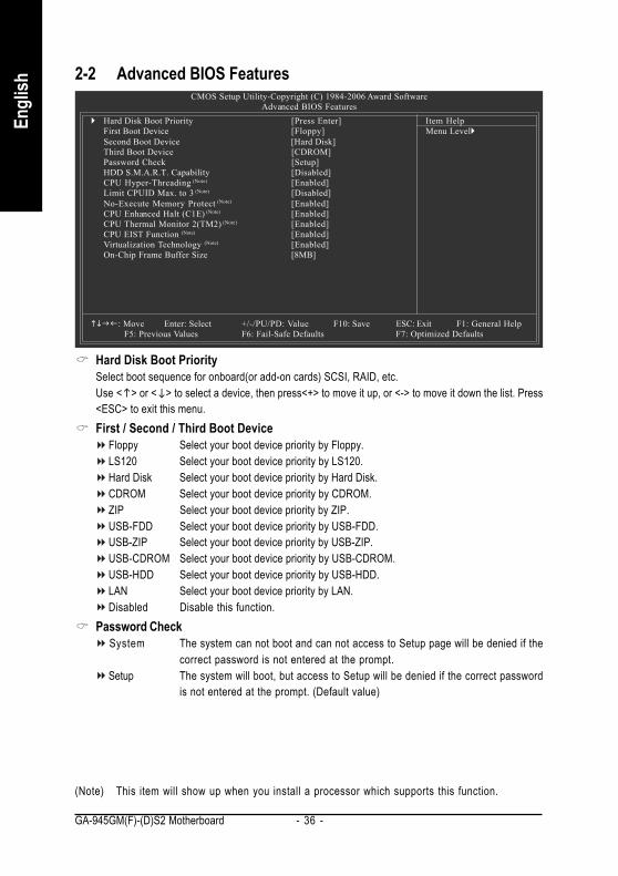
Hard Disk Boot PrioritySelect boot sequence for onboard(or add-on cards) SCSI, RAID, etc.Use < > or < > to select a device, then press<+> to move it up, or <-> to move it down the list. Press<ESC> to exit this menu.First / Second / Third Boot Device
Floppy Select your boot device priority by Floppy.LS120 Select your boot device priority by LS120.Hard Disk Select your boot device priority by Hard Disk.CDROM Select your boot device priority by CDROM.ZIP Select your boot device priority by ZIP.USB-FDD Select your boot device priority by USB-FDD.USB-ZIP Select your boot device priority by USB-ZIP.USB-CDROM Select your boot device priority by USB-CDROM.USB-HDD Select your boot device priority by USB-HDD.LAN Select your boot device priority by LAN.Disabled Disable this function.
Password CheckSystem The system can not boot and can not access to Setup page will be denied if the
correct password is not entered at the prompt.Setup The system will boot, but access to Setup will be denied if the correct password
is not entered at the prompt. (Default value)
CMOS Setup Utility-Copyright (C) 1984-2006 Award SoftwareAdvanced BIOS Features
Hard Disk Boot Priority [Press Enter]First Boot Device [Floppy]Second Boot Device [Hard Disk]Third Boot Device [CDROM]Password Check [Setup]HDD S.M.A.R.T. Capability [Disabled]CPU Hyper-Threading (Note) [Enabled]Limit CPUID Max. to 3 (Note) [Disabled]No-Execute Memory Protect (Note) [Enabled]CPU Enhanced Halt (C1E) (Note) [Enabled]CPU Thermal Monitor 2(TM2) (Note) [Enabled]CPU EIST Function (Note) [Enabled]Virtualization Technology (Note) [Enabled]On-Chip Frame Buffer Size [8MB]
: Move Enter: Select +/-/PU/PD: Value F10: Save ESC: Exit F1: General HelpF5: Previous Values F6: Fail-Safe Defaults F7: Optimized Defaults
Item HelpMenu Level
(Note) This item will show up when you install a processor which supports this function.
BIOS Setup- 37 -
English
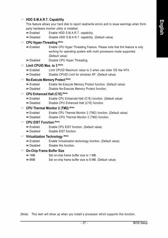
HDD S.M.A.R.T. CapabilityThis feature allows your hard disk to report read/write errors and to issue warnings when third-party hardware monitor utility is installed.
Enabled Enable HDD S.M.A.R.T. capability.Disabled Disable HDD S.M.A.R.T. capability. (Default value)
CPU Hyper-Threading (Note)
Enabled Enable CPU Hyper Threading Feature. Please note that this feature is onlyworking for operating system with multi processors mode supported.(Default value)
Disabled Disable CPU Hyper Threading.Limit CPUID Max. to 3 (Note)
Enabled Limit CPUID Maximum value to 3 when use older OS like NT4.Disabled Disable CPUID Limit for windows XP. (Default value)
No-Execute Memory Protect (Note)
Enabled Enable No-Execute Memory Protect function. (Default value)Disabled Disable No-Execute Memory Protect function.
CPU Enhanced Halt (C1E) (Note)
Enabled Enable CPU Enhanced Halt (C1E) function. (Default value)Disabled Disable CPU Enhanced Halt (C1E) function.
CPU Thermal Monitor 2 (TM2) (Note)
Enabled Enable CPU Thermal Monitor 2 (TM2) function. (Default value)Disabled Disable CPU Thermal Monitor 2 (TM2) function.
CPU EIST Function (Note)
Enabled Enable CPU EIST function. (Default value)Disabled Disable EIST function.
Virtualization Technology (Note)
Enabled Enable Virtualization technology function. (Default value)Disabled Disable this function.
On-Chip Frame Buffer Size1MB Set on-chip frame buffer size to 1 MB.8MB Set on-chip frame buffer size to 8 MB. (Default value)
(Note) This item will show up when you install a processor which supports this function.
GA-945GM(F)-(D)S2 Motherboard - 38 -
Engl
ish
2-3 Integrated Peripherals
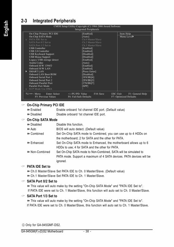
On-Chip Primary PCI IDEEnabled Enable onboard 1st channel IDE port. (Default value)Disabled Disable onboard 1st channel IDE port.
On-Chip SATA ModeDisabled Disable this function.Auto BIOS will auto detect. (Default value)Combined Set On-Chip SATA mode to Combined, you can use up to 4 HDDs on
the motherboard; 2 for SATA and the other for PATA.Enhanced Set On-Chip SATA mode to Enhanced, the motherboard allows up to 6
HDDs to use; 4 for SATA and the other for PATA.Non-Combined Set On-Chip SATA mode to Non-Combined, SATA will be simulated to
PATA mode. Support a maximum of 4 SATA devices. PATA devices will beignored.
PATA IDE Set toCh.0 Master/Slave Set PATA IDE to Ch. 0 Master/Slave. (Default value)Ch.1 Master/Slave Set PATA IDE to Ch. 1 Master/Slave.
SATA Port 0/2 Set toThis value will auto make by the setting "On-Chip SATA Mode" and "PATA IDE Set to".
If PATA IDE were set to Ch. 1 Master/Slave, this function will auto set to Ch. 0 Master/Slave.SATA Port 1/3 Set to
This value will auto make by the setting "On-Chip SATA Mode" and "PATA IDE Set to".If PATA IDE were set to Ch. 0 Master/Slave, this function will auto set to Ch. 1 Master/Slave.
CMOS Setup Utility-Copyright (C) 1984-2006 Award SoftwareIntegrated Peripherals
On-Chip Primary PCI IDE [Enabled]On-Chip SATA Mode [Auto]
x PATA IDE Set to Ch.0 Master/SlaveSATA Port 0/2 Set to Ch.2 Master/SlaveSATA Port 1/3 Set to Ch.3 Master/SlaveUSB Controller [Enabled]USB 2.0 Controller [Enabled]USB Keyboard Support [Disabled]USB Mouse Support [Disabled]Legacy USB storage detect [Enabled]Azalia Codec [Auto]Onboard H/W 13941 [Enabled]Onboard H/W LAN [Enabled]SMART LAN [Press Enter]Onboard LAN Boot ROM [Disabled]Onboard Serial Port 1 [3F8/IRQ4]Onboard Serial Port 2 [2F8/IRQ3]Onboard Parallel Port [378/IRQ7]Parallel Port Mode [SPP]
x ECP Mode Use DMA 3
: Move Enter: Select +/-/PU/PD: Value F10: Save ESC: Exit F1: General HelpF5: Previous Values F6: Fail-Safe Defaults F7: Optimized Defaults
Item HelpMenu Level
Only for GA-945GMF-DS2.
BIOS Setup- 39 -
English
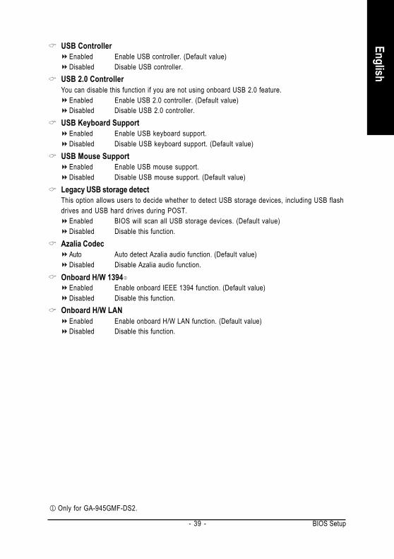
USB ControllerEnabled Enable USB controller. (Default value)Disabled Disable USB controller.
USB 2.0 ControllerYou can disable this function if you are not using onboard USB 2.0 feature.
Enabled Enable USB 2.0 controller. (Default value)Disabled Disable USB 2.0 controller.
USB Keyboard SupportEnabled Enable USB keyboard support.Disabled Disable USB keyboard support. (Default value)
USB Mouse SupportEnabled Enable USB mouse support.Disabled Disable USB mouse support. (Default value)
Legacy USB storage detectThis option allows users to decide whether to detect USB storage devices, including USB flashdrives and USB hard drives during POST.
Enabled BIOS will scan all USB storage devices. (Default value)Disabled Disable this function.
Azalia CodecAuto Auto detect Azalia audio function. (Default value)Disabled Disable Azalia audio function.
Onboard H/W 1394Enabled Enable onboard IEEE 1394 function. (Default value)Disabled Disable this function.
Onboard H/W LANEnabled Enable onboard H/W LAN function. (Default value)Disabled Disable this function.
Only for GA-945GMF-DS2.
GA-945GM(F)-(D)S2 Motherboard - 40 -
Engl
ish
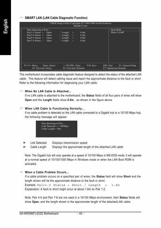
SMART LAN (LAN Cable Diagnostic Function)CMOS Setup Utility-Copyright (C) 1984-2006 Award Software
SMART LANItem HelpMenu Level
Start detecting at Port.....Pair1-2 Status = Open / Length = 0.0mPair3-6 Status = Open / Length = 0.0mPair4-5 Status = Open / Length = 0.0mPair7-8 Status = Open / Length = 0.0m
: Move Enter: Select +/-/PU/PD: Value F10: Save ESC: Exit F1: General HelpF5: Previous Values F6: Fail-Safe Defaults F7: Optimized Defaults
This motherboard incorporates cable diagnostic feature designed to detect the status of the attached LANcable. This feature will detect cabling issue and report the approximate distance to the fault or short.Refer to the following information for diagnosing your LAN cable:
When No LAN Cable Is Attached...If no LAN cable is attached to the motherboard, the Status fields of all four pairs of wires will showOpen and the Length fields show 0.0m, as shown in the figure above.
When LAN Cable Is Functioning Normally...If no cable problem is detected on the LAN cable connected to a Gigabit hub or a 10/100 Mbps hub,the following message will appear:
Link Detected Displays transmission speedCable Length Displays the approximate length of the attached LAN cable
Note: The Gigabit hub will only operate at a speed of 10/100 Mbps in MS-DOS mode; it will operateat a normal speed of 10/100/1000 Mbps in Windows mode or when the LAN Boot ROM isactivated.
When a Cable Problem Occurs...If a cable problem occurs on a specified pair of wires, the Status field will show Short and thelength shown will be the approximate distance to the fault or short.Example: Pair1-2 Status = Short / Length = 1.6mExplanation: A fault or short might occur at about 1.6m on Pair 1-2.
Note: Pair 4-5 and Pair 7-8 are not used in a 10/100 Mbps environment, their Status fields willshow Open, and the length shown is the approximate length of the attached LAN cable.
Start detecting at Port.....Link Detected --> 100MbpsCable Length= 30m
BIOS Setup- 41 -
English
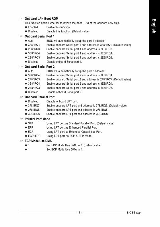
Onboard LAN Boot ROMThis function decide whether to invoke the boot ROM of the onboard LAN chip.
Enabled Enable this function.Disabled Disable this function. (Default value)
Onboard Serial Port 1Auto BIOS will automatically setup the port 1 address.3F8/IRQ4 Enable onboard Serial port 1 and address is 3F8/IRQ4. (Default value)2F8/IRQ3 Enable onboard Serial port 1 and address is 2F8/IRQ3.3E8/IRQ4 Enable onboard Serial port 1 and address is 3E8/IRQ4.2E8/IRQ3 Enable onboard Serial port 1 and address is 2E8/IRQ3.Disabled Disable onboard Serial port 1.
Onboard Serial Port 2Auto BIOS will automatically setup the port 2 address.3F8/IRQ4 Enable onboard Serial port 2 and address is 3F8/IRQ4.2F8/IRQ3 Enable onboard Serial port 2 and address is 2F8/IRQ3. (Default value)3E8/IRQ4 Enable onboard Serial port 2 and address is 3E8/IRQ4.2E8/IRQ3 Enable onboard Serial port 2 and address is 2E8/IRQ3.Disabled Disable onboard Serial port 2.
Onboard Parallel PortDisabled Disable onboard LPT port.378/IRQ7 Enable onboard LPT port and address is 378/IRQ7. (Default value)278/IRQ5 Enable onboard LPT port and address is 278/IRQ5.3BC/IRQ7 Enable onboard LPT port and address is 3BC/IRQ7.
Parallel Port ModeSPP Using LPT port as Standard Parallel Port. (Default value)EPP Using LPT port as Enhanced Parallel Port.ECP Using LPT port as Extended Capabilities Port.ECP+EPP Using LPT port as ECP & EPP mode.
ECP Mode Use DMA3 Set ECP Mode Use DMA to 3. (Default value)1 Set ECP Mode Use DMA to 1.
GA-945GM(F)-(D)S2 Motherboard - 42 -
Engl
ish
2-4 Power Management Setup
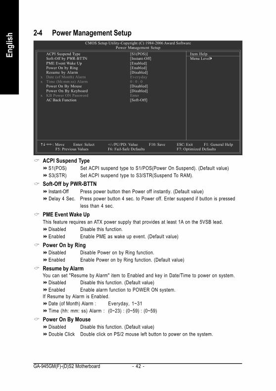
ACPI Suspend TypeS1(POS) Set ACPI suspend type to S1/POS(Power On Suspend). (Default value)S3(STR) Set ACPI suspend type to S3/STR(Suspend To RAM).
Soft-Off by PWR-BTTNInstant-Off Press power button then Power off instantly. (Default value)Delay 4 Sec. Press power button 4 sec. to Power off. Enter suspend if button is pressed
less than 4 sec.PME Event Wake UpThis feature requires an ATX power supply that provides at least 1A on the 5VSB lead.
Disabled Disable this function.Enabled Enable PME as wake up event. (Default value)
Power On by RingDisabled Disable Power on by Ring function.Enabled Enable Power on by Ring function. (Default value)
Resume by AlarmYou can set "Resume by Alarm" item to Enabled and key in Date/Time to power on system.
Disabled Disable this function. (Default value)Enabled Enable alarm function to POWER ON system.
If Resume by Alarm is Enabled.Date (of Month) Alarm : Everyday, 1~31Time (hh: mm: ss) Alarm : (0~23) : (0~59) : (0~59)
Power On By MouseDisabled Disable this function. (Default value)Double Click Double click on PS/2 mouse left button to power on the system.
CMOS Setup Utility-Copyright (C) 1984-2006 Award SoftwarePower Management Setup
ACPI Suspend Type [S1(POS)]Soft-Off by PWR-BTTN [Instant-Off]PME Event Wake Up [Enabled]Power On by Ring [Enabled]Resume by Alarm [Disabled]
x Date (of Month) Alarm Everydayx Time (hh:mm:ss) Alarm 0 : 0 : 0
Power On By Mouse [Disabled]Power On By Keyboard [Disabled]
x KB Power ON Password EnterAC Back Function [Soft-Off]
: Move Enter: Select +/-/PU/PD: Value F10: Save ESC: Exit F1: General HelpF5: Previous Values F6: Fail-Safe Defaults F7: Optimized Defaults
Item HelpMenu Level
BIOS Setup- 43 -
English
Power On By KeyboardDisabled Disable this function. (Default value)Password Enter from 1 to 5 characters to set the keyboard power on password.Keyboard 98 If your keyboard have "POWER Key" button, you can press the key to power
on the system.KB Power ON PasswordWhen "Power On by Keyboard" set at Password, you can set the password here.
Enter Input password(from 1 to 5 characters) and press Enter to set the password.AC BACK Function
Soft-Off When AC-power back to the system, the system will be in "Off" state.(Default value)
Full-On When AC-power back to the system, the system always in "On" state.Memory When AC-power back to the system, the system will return to the Last state
before AC-power off.
GA-945GM(F)-(D)S2 Motherboard - 44 -
Engl
ish
2-5 PnP/PCI Configurations
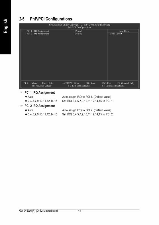
PCI 1 IRQ AssignmentAuto Auto assign IRQ to PCI 1. (Default value)3,4,5,7,9,10,11,12,14,15 Set IRQ 3,4,5,7,9,10,11,12,14,15 to PCI 1.
PCI 2 IRQ AssignmentAuto Auto assign IRQ to PCI 2. (Default value)3,4,5,7,9,10,11,12,14,15 Set IRQ 3,4,5,7,9,10,11,12,14,15 to PCI 2.
CMOS Setup Utility-Copyright (C) 1984-2006 Award SoftwarePnP/PCI Configurations
PCI 1 IRQ Assignment [Auto]PCI 2 IRQ Assignment [Auto]
: Move Enter: Select +/-/PU/PD: Value F10: Save ESC: Exit F1: General HelpF5: Previous Values F6: Fail-Safe Defaults F7: Optimized Defaults
Item HelpMenu Level
BIOS Setup- 45 -
English
2-6 PC Health Status
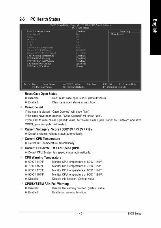
Reset Case Open StatusDisabled Don't reset case open status. (Default value)Enabled Clear case open status at next boot.
Case OpenedIf the case is closed, "Case Opened" will show "No".If the case have been opened, "Case Opened" will show "Yes".If you want to reset "Case Opened" value, set "Reset Case Open Status" to "Enabled" and saveCMOS, your computer will restart.Current Voltage(V) Vcore / DDR18V / +3.3V / +12V
Detect system's voltage status automatically.Current CPU Temperature
Detect CPU temperature automatically.Current CPU/SYSTEM FAN Speed (RPM)
Detect CPU/System fan speed status automatically.CPU Warning Temperature
60oC / 140oF Monitor CPU temperature at 60oC / 140oF.70oC / 158oF Monitor CPU temperature at 70oC / 158oF.80oC / 176oF Monitor CPU temperature at 80oC / 176oF.90oC / 194oF Monitor CPU temperature at 90oC / 194oF.Disabled Disable this function. (Default value)
CPU/SYSTEM FAN Fail WarningDisabled Disable fan warning function. (Default value)Enabled Enable fan warning function.
CMOS Setup Utility-Copyright (C) 1984-2006 Award SoftwarePC Health Status
Reset Case Open Status [Disabled]Case Opened YesVcore OKDDR18V OK+3.3V OK+12V OKCurrent CPU Temperature 43oCCurrent CPU FAN Speed 2880 RPMCurrent SYSTEM FAN Speed 0 RPMCPU Warning Temperature [Disabled]CPU FAN Fail Warning [Disabled]SYSTEM FAN Fail Warning [Disabled]CPU Smart FAN Control [Enabled]CPU Smart FAN Mode [Auto]
: Move Enter: Select +/-/PU/PD: Value F10: Save ESC: Exit F1: General HelpF5: Previous Values F6: Fail-Safe Defaults F7: Optimized Defaults
Item HelpMenu Level
GA-945GM(F)-(D)S2 Motherboard - 46 -
Engl
ish
CPU Smart FAN ControlDisabled Disable this function.Enabled When this function is enabled, CPU fan will run at different speed depending on
CPU temperature. Users can adjust the fan speed with Easy Tune based ontheir requirements. (Default value)
CPU Smart FAN ModeThis option is available only when CPU Smart FAN Control is enabled.
Auto BIOS autodetects the type of CPU fan you installed and sets the optimal CPUSmart FAN control mode for it. (Default value)
Voltage Set to Voltage when you use a CPU fan with a 3-pin fan power cable.PWM Set to PWM when you use a CPU fan with a 4-pin fan power cable.
Note: In fact, the Voltage option can be used for CPU fans with 3-pin or 4-pin power cables.However, some 4-pin CPU fan power cables are not designed following Intel 4-Wire fans PWMcontrol specifications. With such CPU fans, selecting PWM will not effectively reduce the fanspeed.
BIOS Setup- 47 -
English
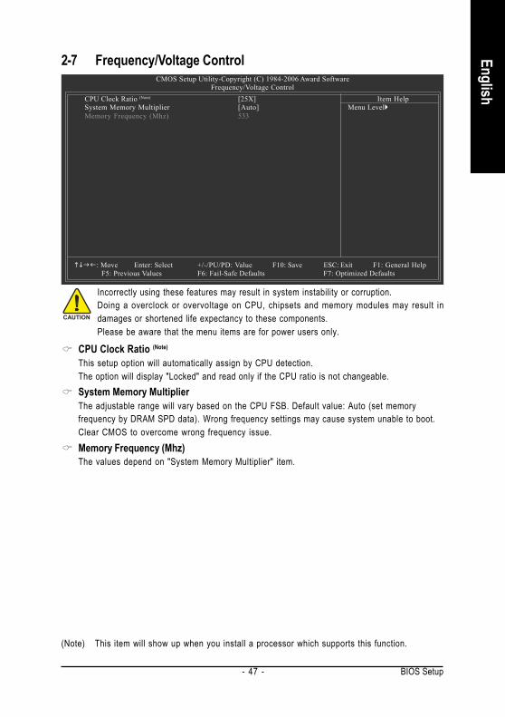
2-7 Frequency/Voltage ControlCMOS Setup Utility-Copyright (C) 1984-2006 Award Software
Frequency/Voltage ControlCPU Clock Ratio (Note) [25X]System Memory Multiplier [Auto]Memory Frequency (Mhz) 533
: Move Enter: Select +/-/PU/PD: Value F10: Save ESC: Exit F1: General HelpF5: Previous Values F6: Fail-Safe Defaults F7: Optimized Defaults
Item HelpMenu Level
CPU Clock Ratio (Note)
This setup option will automatically assign by CPU detection.The option will display "Locked" and read only if the CPU ratio is not changeable.System Memory MultiplierThe adjustable range will vary based on the CPU FSB. Default value: Auto (set memoryfrequency by DRAM SPD data). Wrong frequency settings may cause system unable to boot.Clear CMOS to overcome wrong frequency issue.Memory Frequency (Mhz)The values depend on "System Memory Multiplier" item.
(Note) This item will show up when you install a processor which supports this function.
Incorrectly using these features may result in system instability or corruption.Doing a overclock or overvoltage on CPU, chipsets and memory modules may result indamages or shortened life expectancy to these components.Please be aware that the menu items are for power users only.
GA-945GM(F)-(D)S2 Motherboard - 48 -
Engl
ish
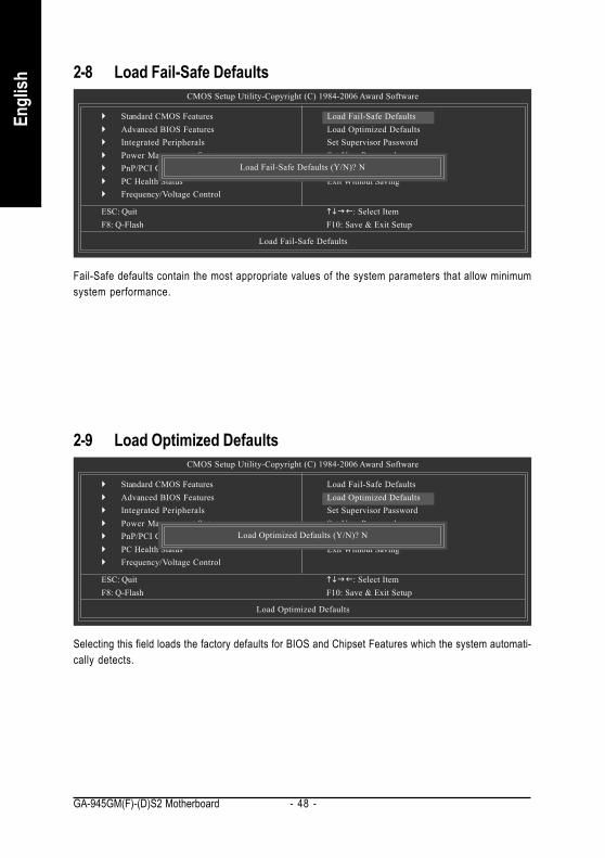
2-8 Load Fail-Safe Defaults
Fail-Safe defaults contain the most appropriate values of the system parameters that allow minimumsystem performance.
CMOS Setup Utility-Copyright (C) 1984-2006 Award Software
Standard CMOS FeaturesAdvanced BIOS FeaturesIntegrated PeripheralsPower Management SetupPnP/PCI ConfigurationsPC Health StatusFrequency/Voltage Control
ESC: Quit : Select ItemF8: Q-Flash F10: Save & Exit Setup
Load Fail-Safe Defaults
Load Fail-Safe DefaultsLoad Optimized DefaultsSet Supervisor PasswordSet User PasswordSave & Exit SetupExit Without Saving
Load Fail-Safe Defaults (Y/N)? N
2-9 Load Optimized Defaults
Selecting this field loads the factory defaults for BIOS and Chipset Features which the system automati-cally detects.
CMOS Setup Utility-Copyright (C) 1984-2006 Award Software
Standard CMOS FeaturesAdvanced BIOS FeaturesIntegrated PeripheralsPower Management SetupPnP/PCI ConfigurationsPC Health StatusFrequency/Voltage Control
ESC: Quit : Select ItemF8: Q-Flash F10: Save & Exit Setup
Load Optimized Defaults
Load Fail-Safe DefaultsLoad Optimized DefaultsSet Supervisor PasswordSet User PasswordSave & Exit SetupExit Without Saving
Load Optimized Defaults (Y/N)? N
BIOS Setup- 49 -
English
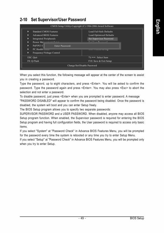
2-10 Set Supervisor/User Password
When you select this function, the following message will appear at the center of the screen to assistyou in creating a password.Type the password, up to eight characters, and press <Enter>. You will be asked to confirm thepassword. Type the password again and press <Enter>. You may also press <Esc> to abort theselection and not enter a password.To disable password, just press <Enter> when you are prompted to enter password. A message"PASSWORD DISABLED" will appear to confirm the password being disabled. Once the password isdisabled, the system will boot and you can enter Setup freely.The BIOS Setup program allows you to specify two separate passwords:SUPERVISOR PASSWORD and a USER PASSWORD. When disabled, anyone may access all BIOSSetup program function. When enabled, the Supervisor password is required for entering the BIOSSetup program and having full configuration fields, the User password is required to access only basicitems.If you select "System" at "Password Check" in Advance BIOS Features Menu, you will be promptedfor the password every time the system is rebooted or any time you try to enter Setup Menu.If you select "Setup" at "Password Check" in Advance BIOS Features Menu, you will be prompted onlywhen you try to enter Setup.
CMOS Setup Utility-Copyright (C) 1984-2006 Award Software
Standard CMOS FeaturesAdvanced BIOS FeaturesIntegrated PeripheralsPower Management SetupPnP/PCI ConfigurationsPC Health StatusFrequency/Voltage Control
ESC: Quit : Select ItemF8: Q-Flash F10: Save & Exit Setup
Change/Set/Disable Password
Load Fail-Safe DefaultsLoad Optimized DefaultsSet Supervisor PasswordSet User PasswordSave & Exit SetupExit Without Saving
Enter Password:

GA-945GM(F)-(D)S2 Motherboard - 50 -
Engl
ish
2-11 Save & Exit Setup
Type "Y" will quit the Setup Utility and save the user setup value to RTC CMOS.Type "N" will return to Setup Utility.
2-12 Exit Without Saving
Type "Y" will quit the Setup Utility without saving to RTC CMOS.Type "N" will return to Setup Utility.
CMOS Setup Utility-Copyright (C) 1984-2006 Award Software
Standard CMOS FeaturesAdvanced BIOS FeaturesIntegrated PeripheralsPower Management SetupPnP/PCI ConfigurationsPC Health StatusFrequency/Voltage Control
ESC: Quit : Select ItemF8: Q-Flash F10: Save & Exit Setup
Abandon all Data
Load Fail-Safe DefaultsLoad Optimized DefaultsSet Supervisor PasswordSet User PasswordSave & Exit SetupExit Without Saving
Quit Without Saving (Y/N)? N
Standard CMOS FeaturesAdvanced BIOS FeaturesIntegrated PeripheralsPower Management SetupPnP/PCI ConfigurationsPC Health StatusFrequency/Voltage Control
ESC: Quit : Select ItemF8: Q-Flash F10: Save & Exit Setup
Save Data to CMOS
Load Fail-Safe DefaultsLoad Optimized DefaultsSet Supervisor PasswordSet User PasswordSave & Exit SetupExit Without Saving
Save to CMOS and EXIT (Y/N)? Y
Install Drivers- 51 -
English
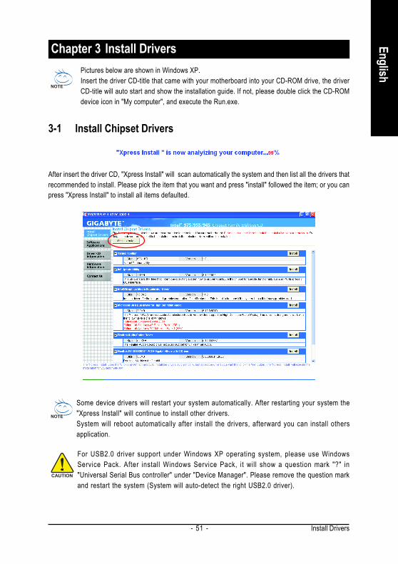
Chapter 3 Install DriversPictures below are shown in Windows XP.Insert the driver CD-title that came with your motherboard into your CD-ROM drive, the driverCD-title will auto start and show the installation guide. If not, please double click the CD-ROMdevice icon in "My computer", and execute the Run.exe.
3-1 Install Chipset Drivers
After insert the driver CD, "Xpress Install" will scan automatically the system and then list all the drivers thatrecommended to install. Please pick the item that you want and press "install" followed the item; or you canpress "Xpress Install" to install all items defaulted.
Some device drivers will restart your system automatically. After restarting your system the"Xpress Install" will continue to install other drivers.System will reboot automatically after install the drivers, afterward you can install othersapplication.
For USB2.0 driver support under Windows XP operating system, please use WindowsService Pack. After install Windows Service Pack, it will show a question mark "?" in"Universal Serial Bus controller" under "Device Manager". Please remove the question markand restart the system (System will auto-detect the right USB2.0 driver).
GA-945GM(F)-(D)S2 Motherboard - 52 -
Engl
ish
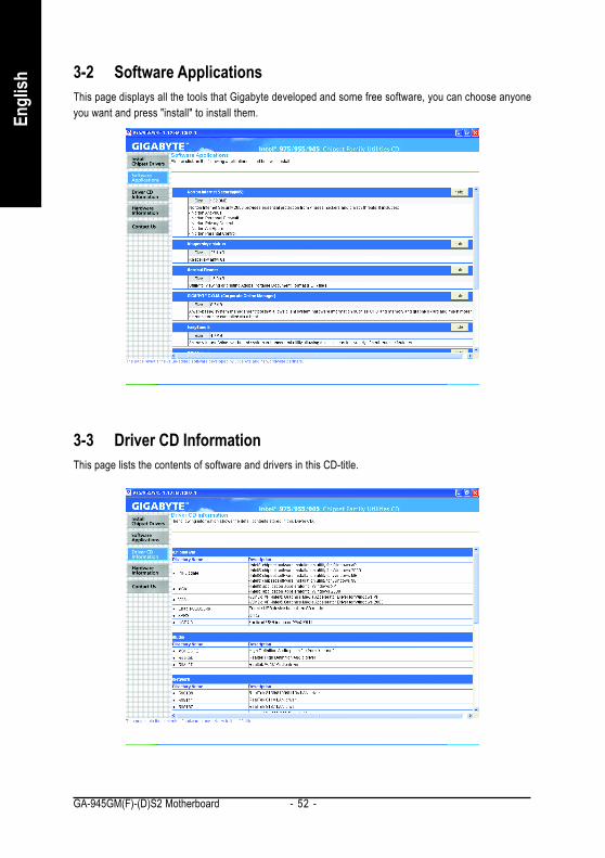
3-2 Software ApplicationsThis page displays all the tools that Gigabyte developed and some free software, you can choose anyoneyou want and press "install" to install them.
3-3 Driver CD InformationThis page lists the contents of software and drivers in this CD-title.
Install Drivers- 53 -
English
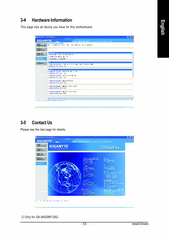
3-4 Hardware InformationThis page lists all device you have for this motherboard.
3-5 Contact UsPlease see the last page for details.
Only for GA-945GMF-DS2.

GA-945GM(F)-(D)S2 Motherboard - 54 -
Engl
ish
Appendix- 55 -
English
Chapter 4 Appendix4-1 Unique Software Utilities(Not all model support these Unique Software Utilities, please check your MB features.)
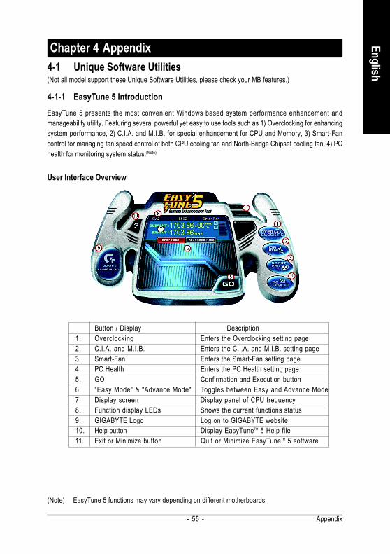
4-1-1 EasyTune 5 IntroductionEasyTune 5 presents the most convenient Windows based system performance enhancement andmanageability utility. Featuring several powerful yet easy to use tools such as 1) Overclocking for enhancingsystem performance, 2) C.I.A. and M.I.B. for special enhancement for CPU and Memory, 3) Smart-Fancontrol for managing fan speed control of both CPU cooling fan and North-Bridge Chipset cooling fan, 4) PChealth for monitoring system status.(Note)
User Interface Overview
(Note) EasyTune 5 functions may vary depending on different motherboards.
Button / Display Description1. Overclocking Enters the Overclocking setting page2. C.I.A. and M.I.B. Enters the C.I.A. and M.I.B. setting page3. Smart-Fan Enters the Smart-Fan setting page4. PC Health Enters the PC Health setting page5. GO Confirmation and Execution button6. "Easy Mode" & "Advance Mode" Toggles between Easy and Advance Mode7. Display screen Display panel of CPU frequency8. Function display LEDs Shows the current functions status9. GIGABYTE Logo Log on to GIGABYTE website10. Help button Display EasyTuneTM 5 Help file11. Exit or Minimize button Quit or Minimize EasyTuneTM 5 software
GA-945GM(F)-(D)S2 Motherboard - 56 -
Engl
ish
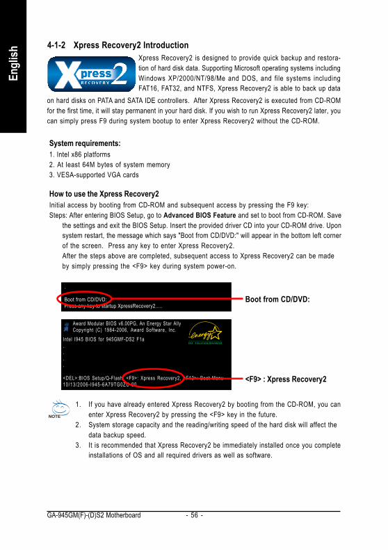
4-1-2 Xpress Recovery2 IntroductionXpress Recovery2 is designed to provide quick backup and restora-tion of hard disk data. Supporting Microsoft operating systems includingWindows XP/2000/NT/98/Me and DOS, and file systems includingFAT16, FAT32, and NTFS, Xpress Recovery2 is able to back up data
How to use the Xpress Recovery2Initial access by booting from CD-ROM and subsequent access by pressing the F9 key:Steps: After entering BIOS Setup, go to Advanced BIOS Feature and set to boot from CD-ROM. Save
the settings and exit the BIOS Setup. Insert the provided driver CD into your CD-ROM drive. Uponsystem restart, the message which says "Boot from CD/DVD:" will appear in the bottom left cornerof the screen. Press any key to enter Xpress Recovery2.After the steps above are completed, subsequent access to Xpress Recovery2 can be madeby simply pressing the <F9> key during system power-on.
1. If you have already entered Xpress Recovery2 by booting from the CD-ROM, you canenter Xpress Recovery2 by pressing the <F9> key in the future.
2. System storage capacity and the reading/writing speed of the hard disk will affect thedata backup speed.
3. It is recommended that Xpress Recovery2 be immediately installed once you completeinstallations of OS and all required drivers as well as software.
on hard disks on PATA and SATA IDE controllers. After Xpress Recovery2 is executed from CD-ROMfor the first time, it will stay permanent in your hard disk. If you wish to run Xpress Recovery2 later, youcan simply press F9 during system bootup to enter Xpress Recovery2 without the CD-ROM.
System requirements:1. Intel x86 platforms2. At least 64M bytes of system memory3. VESA-supported VGA cards
<F9> : Xpress Recovery2
Award Modular BIOS v6.00PG, An Energy Star AllyCopyright (C) 1984-2006, Award Software, Inc.
Intel I945 BIOS for 945GMF-DS2 F1a....
<DEL>:BIOS Setup/Q-Flash, <F9>: Xpress Recovery2, <F12>: Boot Menu10/13 /2006- I945-6A79TG0ZC-00
Boot from CD/DVD:..Boot from CD/DVD:Press any key to startup XpressRecovery2.....
Appendix- 57 -
English
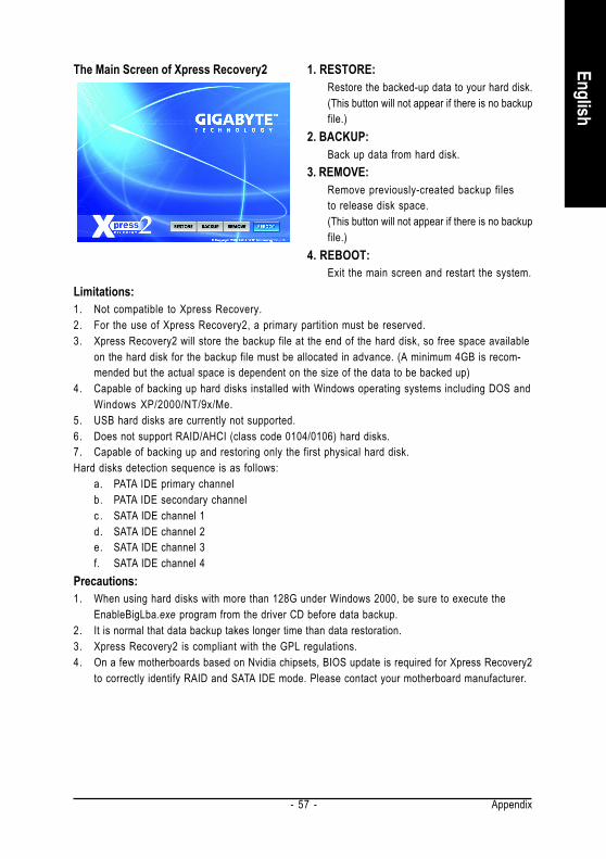
1. RESTORE:Restore the backed-up data to your hard disk.(This button will not appear if there is no backupfile.)
2. BACKUP:Back up data from hard disk.
3. REMOVE:Remove previously-created backup filesto release disk space.(This button will not appear if there is no backupfile.)
4. REBOOT:Exit the main screen and restart the system.
The Main Screen of Xpress Recovery2
Limitations:1. Not compatible to Xpress Recovery.2. For the use of Xpress Recovery2, a primary partition must be reserved.3. Xpress Recovery2 will store the backup file at the end of the hard disk, so free space available
on the hard disk for the backup file must be allocated in advance. (A minimum 4GB is recom-mended but the actual space is dependent on the size of the data to be backed up)
4. Capable of backing up hard disks installed with Windows operating systems including DOS andWindows XP/2000/NT/9x/Me.
5. USB hard disks are currently not supported.6. Does not support RAID/AHCI (class code 0104/0106) hard disks.7. Capable of backing up and restoring only the first physical hard disk.Hard disks detection sequence is as follows:
a. PATA IDE primary channelb. PATA IDE secondary channelc . SATA IDE channel 1d. SATA IDE channel 2e. SATA IDE channel 3f. SATA IDE channel 4
Precautions:1. When using hard disks with more than 128G under Windows 2000, be sure to execute the
EnableBigLba.exe program from the driver CD before data backup.2. It is normal that data backup takes longer time than data restoration.3. Xpress Recovery2 is compliant with the GPL regulations.4. On a few motherboards based on Nvidia chipsets, BIOS update is required for Xpress Recovery2
to correctly identify RAID and SATA IDE mode. Please contact your motherboard manufacturer.
GA-945GM(F)-(D)S2 Motherboard - 58 -
Engl
ish
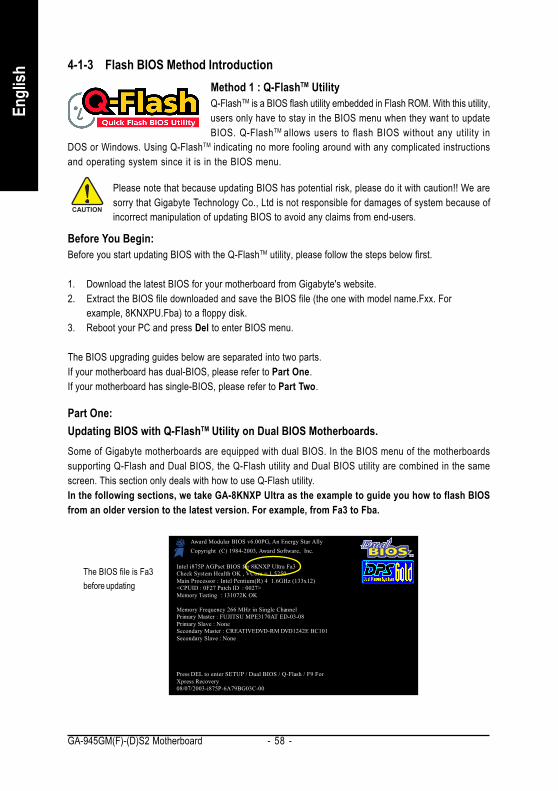
4-1-3 Flash BIOS Method IntroductionMethod 1 : Q-FlashTM UtilityQ-FlashTM is a BIOS flash utility embedded in Flash ROM. With this utility,users only have to stay in the BIOS menu when they want to updateBIOS. Q-FlashTM allows users to flash BIOS without any utility in
DOS or Windows. Using Q-FlashTM indicating no more fooling around with any complicated instructionsand operating system since it is in the BIOS menu.
Please note that because updating BIOS has potential risk, please do it with caution!! We aresorry that Gigabyte Technology Co., Ltd is not responsible for damages of system because ofincorrect manipulation of updating BIOS to avoid any claims from end-users.
Before You Begin:Before you start updating BIOS with the Q-FlashTM utility, please follow the steps below first.
1. Download the latest BIOS for your motherboard from Gigabyte's website.2. Extract the BIOS file downloaded and save the BIOS file (the one with model name.Fxx. For
example, 8KNXPU.Fba) to a floppy disk.3. Reboot your PC and press Del to enter BIOS menu.
The BIOS upgrading guides below are separated into two parts.If your motherboard has dual-BIOS, please refer to Part One.If your motherboard has single-BIOS, please refer to Part Two.
Part One:Updating BIOS with Q-FlashTM Utility on Dual BIOS Motherboards.Some of Gigabyte motherboards are equipped with dual BIOS. In the BIOS menu of the motherboardssupporting Q-Flash and Dual BIOS, the Q-Flash utility and Dual BIOS utility are combined in the samescreen. This section only deals with how to use Q-Flash utility.In the following sections, we take GA-8KNXP Ultra as the example to guide you how to flash BIOSfrom an older version to the latest version. For example, from Fa3 to Fba.
Intel i875P AGPset BIOS for 8KNXP Ultra Fa3Check System Health OK , VCore = 1.5250Main Processor : Intel Pentium(R) 4 1.6GHz (133x12)<CPUID : 0F27 Patch ID : 0027>Memory Testing : 131072K OK
Memory Frequency 266 MHz in Single ChannelPrimary Master : FUJITSU MPE3170AT ED-03-08Primary Slave : NoneSecondary Master : CREATIVEDVD-RM DVD1242E BC101Secondary Slave : None
Press DEL to enter SETUP / Dual BIOS / Q-Flash / F9 ForXpress Recovery08/07/2003-i875P-6A79BG03C-00
Award Modular BIOS v6.00PG, An Energy Star AllyCopyright (C) 1984-2003, Award Software, Inc.
The BIOS file is Fa3before updating
Appendix- 59 -
English
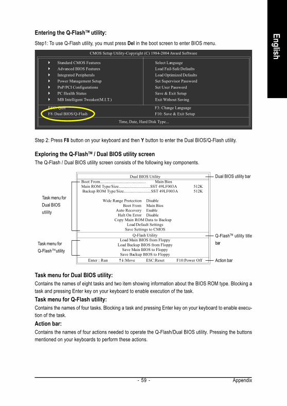
Entering the Q-FlashTM utility:
CMOS Setup Utility-Copyright (C) 1984-2004 Award Software
Standard CMOS FeaturesAdvanced BIOS FeaturesIntegrated PeripheralsPower Management SetupPnP/PCI ConfigurationsPC Health StatusMB Intelligent Tweaker(M.I.T.)
Select LanguageLoad Fail-Safe DefaultsLoad Optimized DefaultsSet Supervisor PasswordSet User PasswordSave & Exit SetupExit Without Saving
ESC: Quit F3: Change LanguageF8: Dual BIOS/Q-Flash F10: Save & Exit Setup
Time, Date, Hard Disk Type...
Step 2: Press F8 button on your keyboard and then Y button to enter the Dual BIOS/Q-Flash utility.
Step1: To use Q-Flash utility, you must press Del in the boot screen to enter BIOS menu.
Exploring the Q-FlashTM / Dual BIOS utility screenThe Q-Flash / Dual BIOS utility screen consists of the following key components.
Task menu for Dual BIOS utility:Contains the names of eight tasks and two item showing information about the BIOS ROM type. Blocking atask and pressing Enter key on your keyboard to enable execution of the task.Task menu for Q-Flash utility:Contains the names of four tasks. Blocking a task and pressing Enter key on your keyboard to enable execu-tion of the task.Action bar:Contains the names of four actions needed to operate the Q-Flash/Dual BIOS utility. Pressing the buttonsmentioned on your keyboards to perform these actions.
Dual BIOS UtilityBoot From......................................... Main BiosMain ROM Type/Size.............................SST 49LF003A 512K Backup ROM Type/Size.........................SST 49LF003A 512K
Wide Range Protection DisableBoot From Main Bios
Auto Recovery EnableHalt On Error Disable
Copy Main ROM Data to BackupLoad Default Settings
Save Settings to CMOSQ-Flash Utility
Load Main BIOS from FloppyLoad Backup BIOS from Floppy
Save Main BIOS to FloppySave Backup BIOS to Floppy
Enter : Run :Move ESC:Reset F10:Power Off
Task menu forDual BIOSutility
Task menu forQ-FlashTM utility
Dual BIOS utility bar
Q-FlashTM utility titlebar
Action bar
GA-945GM(F)-(D)S2 Motherboard - 60 -
Engl
ish
Dual BIOS UtilityBoot From......................................... Main BiosMain ROM Type/Size.............................SST 49LF003A 512K Backup ROM Type/Size.........................SST 49LF003A 512K
Wide Range Protection DisableBoot From Main Bios
Auto Recovery EnableHalt On Error Disable
Copy Main ROM Data to BackupLoad Default Settings
Save Settings to CMOSQ-Flash Utility
Load Main BIOS from FloppyLoad Backup BIOS from Floppy
Save Main BIOS to FloppySave Backup BIOS to Floppy
Enter : Run :Move ESC:Reset F10:Power Off
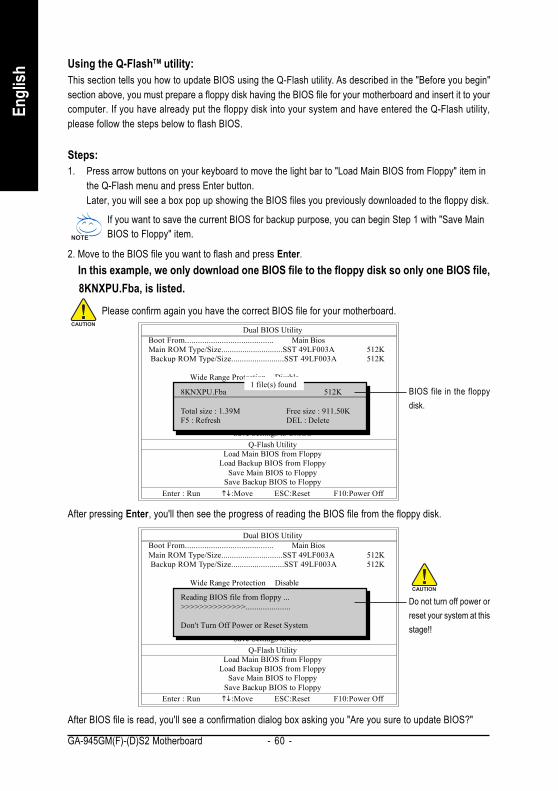
Using the Q-FlashTM utility:This section tells you how to update BIOS using the Q-Flash utility. As described in the "Before you begin"section above, you must prepare a floppy disk having the BIOS file for your motherboard and insert it to yourcomputer. If you have already put the floppy disk into your system and have entered the Q-Flash utility,please follow the steps below to flash BIOS.
Steps:1. Press arrow buttons on your keyboard to move the light bar to "Load Main BIOS from Floppy" item in
the Q-Flash menu and press Enter button.Later, you will see a box pop up showing the BIOS files you previously downloaded to the floppy disk.
If you want to save the current BIOS for backup purpose, you can begin Step 1 with "Save MainBIOS to Floppy" item.
2. Move to the BIOS file you want to flash and press Enter. In this example, we only download one BIOS file to the floppy disk so only one BIOS file, 8KNXPU.Fba, is listed.
Please confirm again you have the correct BIOS file for your motherboard.
1 file(s) found8KNXPU.Fba 512K
Total size : 1.39M Free size : 911.50KF5 : Refresh DEL : Delete
BIOS file in the floppydisk.
Dual BIOS UtilityBoot From......................................... Main BiosMain ROM Type/Size.............................SST 49LF003A 512K Backup ROM Type/Size.........................SST 49LF003A 512K
Wide Range Protection DisableBoot From Main Bios
Auto Recovery EnableHalt On Error Disable
Copy Main ROM Data to BackupLoad Default Settings
Save Settings to CMOSQ-Flash Utility
Load Main BIOS from FloppyLoad Backup BIOS from Floppy
Save Main BIOS to FloppySave Backup BIOS to Floppy
Enter : Run :Move ESC:Reset F10:Power Off
Reading BIOS file from floppy ...>>>>>>>>>>>>>>.....................
Don't Turn Off Power or Reset System
Do not turn off power orreset your system at thisstage!!
After pressing Enter, you'll then see the progress of reading the BIOS file from the floppy disk.
After BIOS file is read, you'll see a confirmation dialog box asking you "Are you sure to update BIOS?"
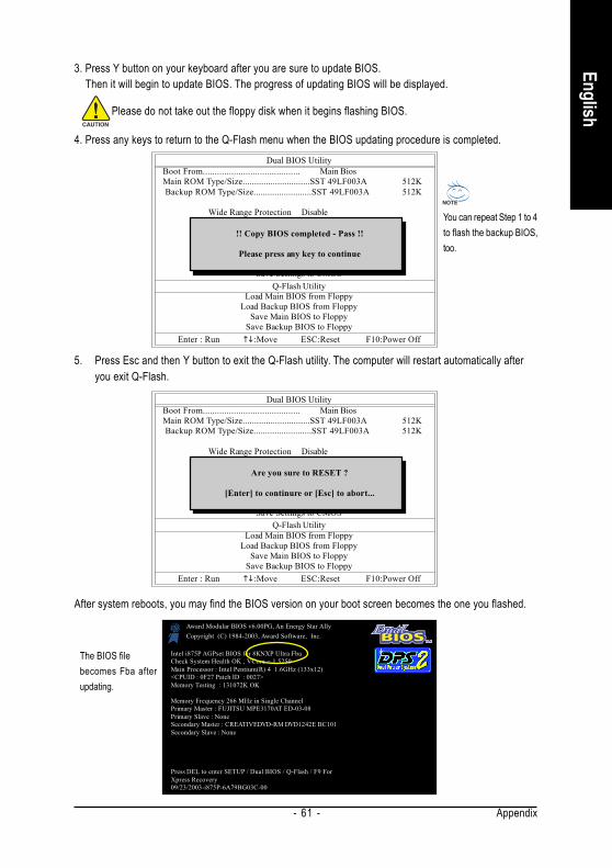
Appendix- 61 -
English
3. Press Y button on your keyboard after you are sure to update BIOS. Then it will begin to update BIOS. The progress of updating BIOS will be displayed.
Dual BIOS UtilityBoot From......................................... Main BiosMain ROM Type/Size.............................SST 49LF003A 512K Backup ROM Type/Size.........................SST 49LF003A 512K
Wide Range Protection DisableBoot From Main Bios
Auto Recovery EnableHalt On Error Disable
Copy Main ROM Data to BackupLoad Default Settings
Save Settings to CMOSQ-Flash Utility
Load Main BIOS from FloppyLoad Backup BIOS from Floppy
Save Main BIOS to FloppySave Backup BIOS to Floppy
Enter : Run :Move ESC:Reset F10:Power Off
!! Copy BIOS completed - Pass !!
Please press any key to continue
Please do not take out the floppy disk when it begins flashing BIOS.
4. Press any keys to return to the Q-Flash menu when the BIOS updating procedure is completed.
You can repeat Step 1 to 4to flash the backup BIOS,too.
Dual BIOS UtilityBoot From......................................... Main BiosMain ROM Type/Size.............................SST 49LF003A 512K Backup ROM Type/Size.........................SST 49LF003A 512K
Wide Range Protection DisableBoot From Main Bios
Auto Recovery EnableHalt On Error Disable
Copy Main ROM Data to BackupLoad Default Settings
Save Settings to CMOSQ-Flash Utility
Load Main BIOS from FloppyLoad Backup BIOS from Floppy
Save Main BIOS to FloppySave Backup BIOS to Floppy
Enter : Run :Move ESC:Reset F10:Power Off
Are you sure to RESET ?
[Enter] to continure or [Esc] to abort...
5. Press Esc and then Y button to exit the Q-Flash utility. The computer will restart automatically afteryou exit Q-Flash.
After system reboots, you may find the BIOS version on your boot screen becomes the one you flashed.
Intel i875P AGPset BIOS for 8KNXP Ultra FbaCheck System Health OK , VCore = 1.5250Main Processor : Intel Pentium(R) 4 1.6GHz (133x12)<CPUID : 0F27 Patch ID : 0027>Memory Testing : 131072K OK
Memory Frequency 266 MHz in Single ChannelPrimary Master : FUJITSU MPE3170AT ED-03-08Primary Slave : NoneSecondary Master : CREATIVEDVD-RM DVD1242E BC101Secondary Slave : None
Press DEL to enter SETUP / Dual BIOS / Q-Flash / F9 ForXpress Recovery09/23/2003-i875P-6A79BG03C-00
Award Modular BIOS v6.00PG, An Energy Star AllyCopyright (C) 1984-2003, Award Software, Inc.
The BIOS filebecomes Fba afterupdating.
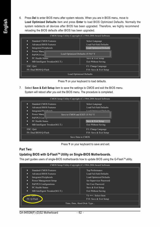
GA-945GM(F)-(D)S2 Motherboard - 62 -
Engl
ish
CMOS Setup Utility-Copyright (C) 1984-2004 Award Software
Standard CMOS FeaturesAdvanced BIOS FeaturesIntegrated PeripheralsPower Management SetupPnP/PCI ConfigurationsPC Health StatusMB Intelligent Tweaker(M.I.T.)
ESC: Quit F3: Change LanguageF8: Dual BIOS/Q-Flash F10: Save & Exit Setup
Load Optimized Defaults
6. Press Del to enter BIOS menu after system reboots. When you are in BIOS menu, move toLoad Optimized Defaults item and press Enter to load BIOS Optimized Defaults. Normally thesystem redetects all devices after BIOS has been upgraded. Therefore, we highly recommendreloading the BIOS defaults after BIOS has been upgraded.
Select LanguageLoad Fail-Safe DefaultsLoad Optimized DefaultsSet Supervisor PasswordSet User PasswordSave & Exit SetupExit Without Saving
Load Optimized Defaults (Y/N)? Y
Press Y on your keyboard to load defaults.
CMOS Setup Utility-Copyright (C) 1984-2004 Award Software
Standard CMOS FeaturesAdvanced BIOS FeaturesIntegrated PeripheralsPower Management SetupPnP/PCI ConfigurationsPC Health StatusMB Intelligent Tweaker(M.I.T.)
ESC: Quit F3: Change LanguageF8: Dual BIOS/Q-Flash F10: Save & Exit Setup
Save Data to CMOS
7. Select Save & Exit Setup item to save the settings to CMOS and exit the BIOS menu.System will reboot after you exit the BIOS menu. The procedure is completed.
Select LanguageLoad Fail-Safe DefaultsLoad Optimized DefaultsSet Supervisor PasswordSet User PasswordSave & Exit SetupExit Without Saving
Save to CMOS and EXIT (Y/N)? Y
Press Y on your keyboard to save and exit.Part Two:Updating BIOS with Q-FlashTM Utility on Single-BIOS Motherboards.This part guides users of single-BIOS motherboards how to update BIOS using the Q-FlashTM utility.
CMOS Setup Utility-Copyright (C) 1984-2004 Award Software
Standard CMOS FeaturesAdvanced BIOS FeaturesIntegrated PeripheralsPower Management SetupPnP/PCI ConfigurationsPC Health StatusMB Intelligent Tweaker(M.I.T.)
Top PerformanceLoad Fail-Safe DefaultsLoad Optimized DefaultsSet Supervisor PasswordSet User PasswordSave & Exit SetupExit Without Saving
Esc: Quit : Select ItemF8: Q-Flash F10: Save & Exit Setup
Time, Date, Hard Disk Type...
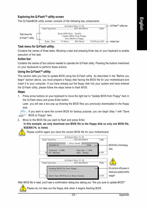
Appendix- 63 -
English
Exploring the Q-FlashTM utility screenThe Q-FlashBIOS utility screen consists of the following key components.
Task menu for Q-Flash utility:Contains the names of three tasks. Blocking a task and pressing Enter key on your keyboard to enableexecution of the task.Action bar:Contains the names of four actions needed to operate the Q-Flash utility. Pressing the buttons mentionedon your keyboards to perform these actions.Using the Q-FlashTM utility:This section tells you how to update BIOS using the Q-Flash utility. As described in the "Before youbegin" section above, you must prepare a floppy disk having the BIOS file for your motherboard andinsert it to your computer. If you have already put the floppy disk into your system and have enteredthe Q-Flash utility, please follow the steps below to flash BIOS.Steps:1. Press arrow buttons on your keyboard to move the light bar to "Update BIOS from Floppy" item in
the Q-Flash menu and press Enter button.Later, you will see a box pop up showing the BIOS files you previously downloaded to the floppydisk.
If you want to save the current BIOS for backup purpose, you can begin Step 1 with "SaveBIOS to Floppy" item.
2. Move to the BIOS file you want to flash and press Enter. In this example, we only download one BIOS file to the floppy disk so only one BIOS file, 8GE800.F4, is listed.
Please confirm again you have the correct BIOS file for your motherboard.Q-Flash Utility V1.30
Flash Type/Size.................................SST 49LF002A 256K
Keep DMI Data EnableUpdate BIOS from Floppy
Save BIOS to FloppyEnter : Run :Move ESC:Reset F10:Power Off
1 file(s) found8GE800.F4 256K
Total size : 1.39M Free size : 1.14MF5 : Refresh DEL : Delete
BIOS file in the floppydisk.
Q-Flash Utility V1.30 Flash Type/Size.................................SST 49LF002A 256K
Keep DMI Data EnableUpdate BIOS from Floppy
Save BIOS to FloppyEnter : Run :Move ESC:Reset F10:Power Off
Reading BIOS file from floppy ...>>>>>>>>>>>>>>.....................
Don't Turn Off Power or Reset System
Do not turn off power orreset your system at thisstage!!
After BIOS file is read, you'll see a confirmation dialog box asking you "Are you sure to update BIOS?"
Please do not take out the floppy disk when it begins flashing BIOS.
Q-Flash Utility V1.30 Flash Type/Size.................................SST 49LF003A 256K
Keep DMI Data EnableUpdate BIOS from Floppy
Save BIOS to FloppyEnter : Run :Move ESC:Reset F10:Power Off
Task menu forQ-FlashTM utility
Q-FlashTM utility bar
Action bar
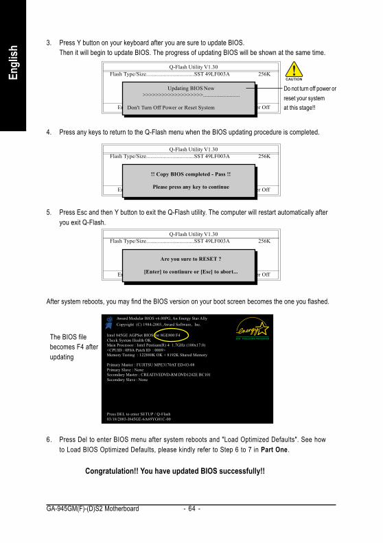
GA-945GM(F)-(D)S2 Motherboard - 64 -
Engl
ish
3. Press Y button on your keyboard after you are sure to update BIOS.Then it will begin to update BIOS. The progress of updating BIOS will be shown at the same time.
Q-Flash Utility V1.30 Flash Type/Size.................................SST 49LF003A 256K
Keep DMI Data EnableUpdate BIOS from Floppy
Save BIOS to FloppyEnter : Run :Move ESC:Reset F10:Power Off
Updating BIOS Now>>>>>>>>>>>>>>>>>>>.........................
Don't Turn Off Power or Reset System
Do not turn off power orreset your systemat this stage!!
4. Press any keys to return to the Q-Flash menu when the BIOS updating procedure is completed.
Q-Flash Utility V1.30 Flash Type/Size.................................SST 49LF003A 256K
Keep DMI Data EnableUpdate BIOS from Floppy
Save BIOS to FloppyEnter : Run :Move ESC:Reset F10:Power Off
!! Copy BIOS completed - Pass !!
Please press any key to continue
5. Press Esc and then Y button to exit the Q-Flash utility. The computer will restart automatically afteryou exit Q-Flash.
Q-Flash Utility V1.30 Flash Type/Size.................................SST 49LF003A 256K
Keep DMI Data EnableUpdate BIOS from Floppy
Save BIOS to FloppyEnter : Run :Move ESC:Reset F10:Power Off
Are you sure to RESET ?
[Enter] to continure or [Esc] to abort...
After system reboots, you may find the BIOS version on your boot screen becomes the one you flashed.
Intel 845GE AGPSet BIOS for 8GE800 F4Check System Health OKMain Processor : Intel Pentium(R) 4 1.7GHz (100x17.0)<CPUID : 0F0A Patch ID : 0009>Memory Testing : 122880K OK + 8192K Shared Memory
Primary Master : FUJITSU MPE3170AT ED-03-08Primary Slave : NoneSecondary Master : CREATIVEDVD-RM DVD1242E BC101Secondary Slave : None
Press DEL to enter SETUP / Q-Flash03/18/2003-I845GE-6A69YG01C-00
Award Modular BIOS v6.00PG, An Energy Star AllyCopyright (C) 1984-2003, Award Software, Inc.
The BIOS filebecomes F4 afterupdating
6. Press Del to enter BIOS menu after system reboots and "Load Optimized Defaults". See howto Load BIOS Optimized Defaults, please kindly refer to Step 6 to 7 in Part One.
Congratulation!! You have updated BIOS successfully!!
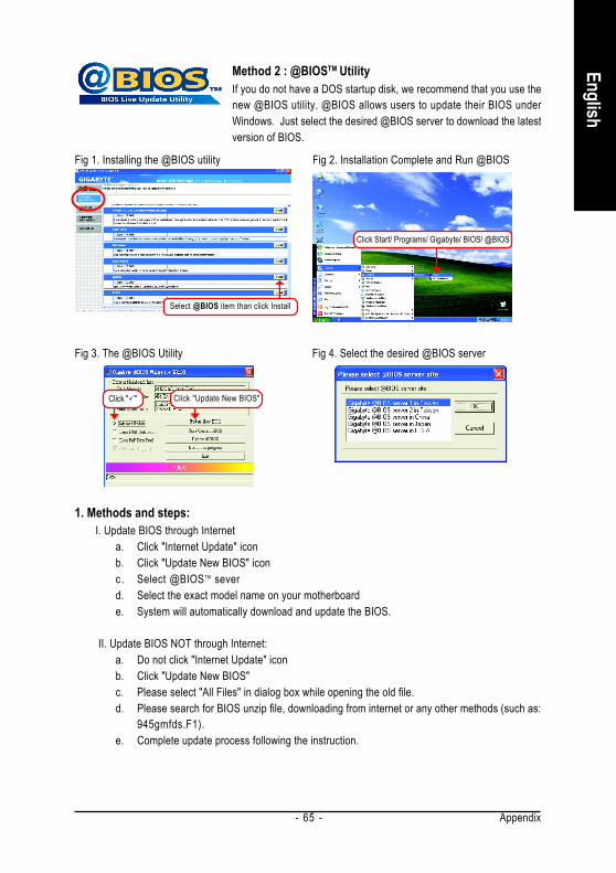
Appendix- 65 -
English
Method 2 : @BIOSTM UtilityIf you do not have a DOS startup disk, we recommend that you use thenew @BIOS utility. @BIOS allows users to update their BIOS underWindows. Just select the desired @BIOS server to download the latestversion of BIOS.
1. Methods and steps:I. Update BIOS through Internet
a. Click "Internet Update" iconb. Click "Update New BIOS" iconc . Select @BIOSTM severd. Select the exact model name on your motherboarde. System will automatically download and update the BIOS.
II. Update BIOS NOT through Internet:a. Do not click "Internet Update" iconb. Click "Update New BIOS"c. Please select "All Files" in dialog box while opening the old file.d. Please search for BIOS unzip file, downloading from internet or any other methods (such as:
945gmfds.F1).e. Complete update process following the instruction.
Fig 1. Installing the @BIOS utility Fig 2. Installation Complete and Run @BIOS
Fig 3. The @BIOS Utility Fig 4. Select the desired @BIOS server
Click " "
Select @BIOS item than click Install
Click Start/ Programs/ Gigabyte/ BIOS/ @BIOS
Click "Update New BIOS"
GA-945GM(F)-(D)S2 Motherboard - 66 -
Engl
ish
III. Save BIOSIn the very beginning, there is "Save Current BIOS" icon shown in dialog box. It means to save thecurrent BIOS version.
IV. Check out supported motherboard and Flash ROM:In the very beginning, there is "About this program" icon shown in dialog box. It can help you check outwhich kind of motherboard and which brand of Flash ROM are supported.
2. Note:I. In method I, if it shows two or more motherboard's model names to be selected, please make
sure your motherboard's model name again. Selecting wrong model name will cause thesystem unbooted.
II. In method II, be sure that motherboard's model name in BIOS unzip file are the same as yourmotherboard's. Otherwise, your system won't boot.
III. In method I, if the BIOS file you need cannot be found in @BIOSTM server, please go ontoGigabyte's web site for downloading and updating it according to method II.
IV. Please note that any interruption during updating will cause system unbooted.V. Do not use @BIOS and C.O.M. (Corporate Online Management) at the same time.
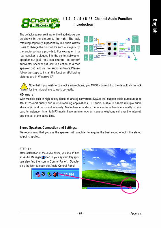
Appendix- 67 -
English
4-1-4 2- / 4- / 6- / 8- Channel Audio FunctionIntroduction
STEP 1 :After installation of the audio driver, you should findan Audio Manager icon in your system tray (youcan also find the icon in Control Panel). Double-click the icon to open the Audio Control Panel.
Note that if you wish to connect a microphone, you MUST connect it to the default Mic In jackfor the microphone to work correctly.
The default speaker settings for the 6 audio jacks areas shown in the picture to the right. The jackretasking capability supported by HD Audio allowsusers to change the function for each audio jack bythe audio software provided. For example, if arear speaker is plugged into the center/subwooferspeaker out jack, you can change the center/subwoofer speaker out jack to fucntion as a rearspeaker out jack via the audio software.Pleasefollow the steps to install the function. (Followingpictures are in Windows XP)
HD AudioWith multiple built-in high quality digital-to-analog converters (DACs) that support audio output at up to192 kHz/24-bit quality and multi-streaming applications, HD Audio is able to handle multiple audiostreams (in and out) simultaneously. Multi-channel audio experiences have become a reality so youcan, for instance, listen to MP3 music, have an Internet chat, make a telephone call over the Internet,and etc. all at the same time.
Stereo Speakers Connection and Settings:We recommend that you use the speaker with amplifier to acquire the best sound effect if the stereooutput is applied.
Line In
Line Out(Front Speaker Out)
Mic In
Rear Speaker Out
Center/SubwooferSpeaker Out
Side SpeakerOut
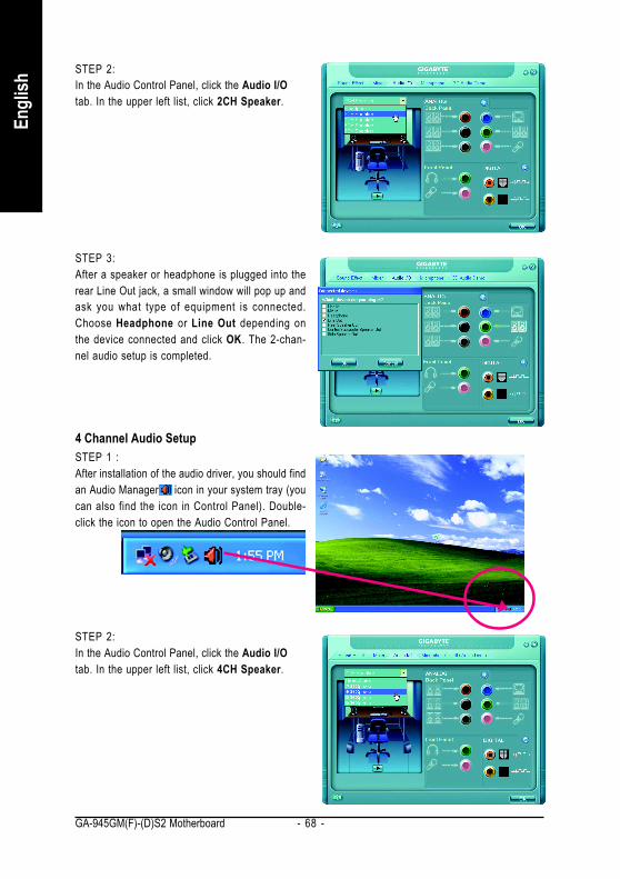
GA-945GM(F)-(D)S2 Motherboard - 68 -
Engl
ish
STEP 3:After a speaker or headphone is plugged into therear Line Out jack, a small window will pop up andask you what type of equipment is connected.Choose Headphone or Line Out depending onthe device connected and click OK. The 2-chan-nel audio setup is completed.
STEP 2:In the Audio Control Panel, click the Audio I/Otab. In the upper left list, click 2CH Speaker.
4 Channel Audio SetupSTEP 1 :After installation of the audio driver, you should findan Audio Manager icon in your system tray (youcan also find the icon in Control Panel). Double-click the icon to open the Audio Control Panel.
STEP 2:In the Audio Control Panel, click the Audio I/Otab. In the upper left list, click 4CH Speaker.
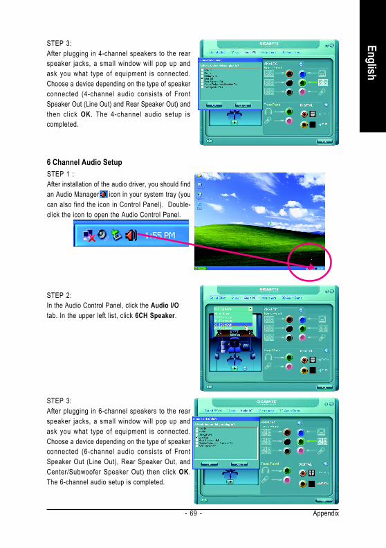
Appendix- 69 -
English
6 Channel Audio SetupSTEP 1 :After installation of the audio driver, you should findan Audio Manager icon in your system tray (youcan also find the icon in Control Panel). Double-click the icon to open the Audio Control Panel.
STEP 3:After plugging in 4-channel speakers to the rearspeaker jacks, a small window will pop up andask you what type of equipment is connected.Choose a device depending on the type of speakerconnected (4-channel audio consists of FrontSpeaker Out (Line Out) and Rear Speaker Out) andthen click OK. The 4-channel audio setup iscompleted.
STEP 2:In the Audio Control Panel, click the Audio I/Otab. In the upper left list, click 6CH Speaker.
STEP 3:After plugging in 6-channel speakers to the rearspeaker jacks, a small window will pop up andask you what type of equipment is connected.Choose a device depending on the type of speakerconnected (6-channel audio consists of FrontSpeaker Out (Line Out), Rear Speaker Out, andCenter/Subwoofer Speaker Out) then click OK.The 6-channel audio setup is completed.
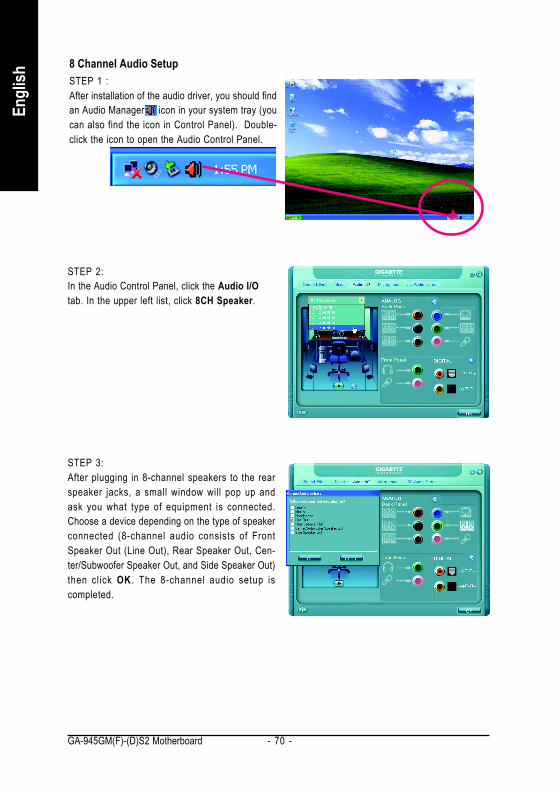
GA-945GM(F)-(D)S2 Motherboard - 70 -
Engl
ish
STEP 2:In the Audio Control Panel, click the Audio I/Otab. In the upper left list, click 8CH Speaker.
STEP 3:After plugging in 8-channel speakers to the rearspeaker jacks, a small window will pop up andask you what type of equipment is connected.Choose a device depending on the type of speakerconnected (8-channel audio consists of FrontSpeaker Out (Line Out), Rear Speaker Out, Cen-ter/Subwoofer Speaker Out, and Side Speaker Out)then click OK . The 8-channel audio setup iscompleted.
8 Channel Audio SetupSTEP 1 :After installation of the audio driver, you should findan Audio Manager icon in your system tray (youcan also find the icon in Control Panel). Double-click the icon to open the Audio Control Panel.
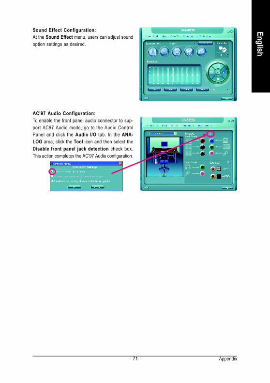
Appendix- 71 -
English
Sound Effect Configuration:At the Sound Effect menu, users can adjust soundoption settings as desired.
AC'97 Audio Configuration:To enable the front panel audio connector to sup-port AC97 Audio mode, go to the Audio ControlPanel and click the Audio I/O tab. In the ANA-LOG area, click the Tool icon and then select theDisable front panel jack detection check box.This action completes the AC'97 Audio configuration.

GA-945GM(F)-(D)S2 Motherboard - 72 -
Engl
ish
4-2 TroubleshootingBelow is a collection of general asked questions. To check general asked questions based on a specificmotherboard model, please log on to http://www.gigabyte.com.tw
Question 1: I cannot see some options that were included in previous BIOS after updating BIOS. Why?Answer: Some advanced options are hidden in new BIOS version. Please press Ctrl and F1 keys afterentering BIOS menu and you will be able to see these options.
Questions 2: Why is the light of my keyboard/optical mouse still on after computer shuts down?Answer: In some boards, a small amount of electricity is kept on standby after computer shuts down andthat's why the light is still on.
Question 3: How do I clear CMOS?Answer: If your board has a Clear CMOS jumper, please refer to the Clear CMOS steps in the manual. If yourboard doesn't have such jumper, you can take off the on-board battery to leak voltage to clear CMOS.Please refer to the steps below:
Steps:1. Turn off power.2. Disconnect the power cord from MB.3. Take out the battery gently and put it aside for about 1 minute (Or you can use a metal object
to connect the positive and negative pins in the battery holder to makethem short for 5seconds).
4. Re-insert the battery to the battery holder.5. Connect power cord to MB again and turn on power.6. Press Del to enter BIOS and load Fail-Safe Defaults(or load Optimized Defaults).7. Save changes and reboot the system.
Question 4: Why do I still get a weak sound after turning up the speaker to the maximum volume?Answer: Please make sure the speaker you are using is equipped with an internal amplifier. If not, pleasechange another speaker with power/amplifier and try again later.
Question 5: Sometimes I hear different continuous beeps from computer after system boots up. What dothese beeps usually stand for?Answer: The beep codes below may help you identify the possible computer problems. However, they areonly for reference purposes. The situations might differ from case to case.
AWARD BIOS Beep Codes1 short: System boots successfully2 short: CMOS setting error1 long 1 short: DRAM or M/B error1 long 2 short: Monitor or display card error1 long 3 short: Keyboard error1 long 9 short: BIOS ROM errorContinuous long beeps: DRAM errorContinuous short beeps: Power error

Appendix- 73 -
English

GA-945GM(F)-(D)S2 Motherboard - 74 -
Engl
ish

Appendix- 75 -
English

GA-945GM(F)-(D)S2 Motherboard - 76 -
Engl
ish

Appendix- 77 -
English
GA-945GM(F)-(D)S2 Motherboard - 78 -
Engl
ish Contact Us
Taiwan (Headquarters)GIGA-BYTE TECHNOLOGY CO., LTD.Address: No.6, Bau Chiang Road, Hsin-Tien,Taipei 231, Taiwan TEL: +886-2-8912-4888 FAX: +886-2-8912-4003Tech. and Non-Tech. Support (Sales/Marketing) :http://ggts.gigabyte.com.twWEB address (English): http://www.gigabyte.com.twWEB address (Chinese): http://www.gigabyte.tw
U.S.A.G.B.T. INC.TEL: +1-626-854-9338FAX: +1-626-854-9339Tech. Support:http://rma.gigabyte-usa.comWeb address: http://www.gigabyte.us
MexicoG.B.T Inc (USA)Tel: +1-626-854-9338 x 215 (Soporte de habla hispano)FAX: +1-626-854-9339Correo: [email protected]. Support:http://rma.gigabyte-usa.comWeb address: http://www.gigabyte-latam.com
JapanNIPPON GIGA-BYTE CORPORATIONWEB address : http://www.gigabyte.co.jp
SingaporeGIGA-BYTE SINGAPORE PTE. LTD.WEB address : http://www.gigabyte.com.sg
ChinaNINGBO G.B.T. TECH. TRADING CO., LTD.WEB address : http://www.gigabyte.cnShanghaiTEL: +86-21-63410999FAX: +86-21-63410100BeijingTEL: +86-10-62102838FAX: +86-10-62102848WuhanTEL: +86-27-87851061FAX: +86-27-87851330GuangZhouTEL: +86-20-87540700FAX: +86-20-87544306 ext. 333ChengduTEL: +86-28-85236930FAX: +86-28-85256822 ext. 814XianTEL: +86-29-85531943FAX: +86-29-85539821ShenyangTEL: +86-24-83992901FAX: +86-24-83992909
IndiaGIGABYTE TECHNOLOGY (INDIA) LIMITEDWEB address : http://www.gigabyte.in
AustraliaGIGABYTE TECHNOLOGY PTY. LTD.WEB address : http://www.gigabyte.com.au
Appendix- 79 -
English
GermanyG.B.T. TECHNOLOGY TRADING GMBHWEB address : http://www.gigabyte.de
U.K.G.B.T. TECH. CO., LTD.WEB address : http://www.giga-byte.co.uk
The NetherlandsGIGA-BYTE TECHNOLOGY B.V.WEB address : http://www.giga-byte.nl
FranceGIGABYTE TECHNOLOGY FRANCEWEB address : http://www.gigabyte.fr
ItalyWEB address : http://www.giga-byte.it
SpainGIGA-BYTE SPAINWEB address : http://www.giga-byte.es
Czech RepublicRepresentative Office Of GIGA-BYTE Technology Co., Ltd.in CZECH REPUBLICWEB address : http://www.gigabyte.cz
TurkeyRepresentative Office Of GIGA-BYTE Technology Co., Ltd.in TURKEYWEB address : http://www.gigabyte.com.tr
To submit a technical or non-technical (Sales/Marketing) question, please link to :http://ggts.gigabyte.com.twThen select your language to enter the system.
RussiaMoscow Representative Office Of GIGA-BYTE TechnologyCo., Ltd.WEB address : http://www.gigabyte.ru
LatviaGIGA-BYTE LatviaWEB address : http://www.gigabyte.com.lv
PolandOffice of GIGA-BYTE TECHNOLOGY Co., Ltd. in POLANDWEB address : http://www.gigabyte.pl
UkraineWEB address : http://www.gigabyte.kiev.ua
RomaniaRepresentative Office Of GIGA-BYTE Technology Co., Ltd.in RomaniaWEB address : http://www.gigabyte.com.ro
Serbia & MontenegroRepresentative Office Of GIGA-BYTE Technology Co., Ltd.in SERBIA & MONTENEGROWEB address : http://www.gigabyte.co.yu
GIGABYTE Global Service System
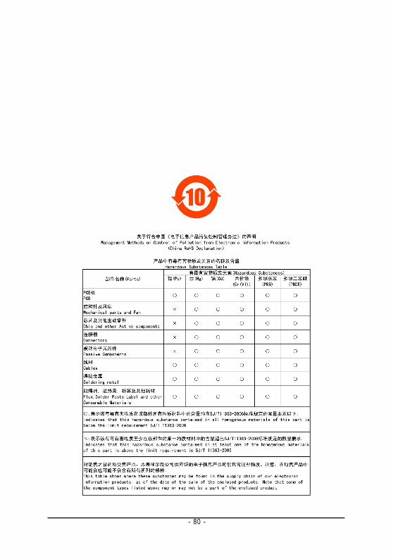
- 80 -
Engl
ish