Embed Size (px)
Citation preview

Safety Controller
G9SPEasy programming for complex safety control• Stand-alone Safety Controller for small and mid-sized
machinery• Three types of CPU with different I/O size to suit the application• Four types of Expansion I/O Units for hard-wired diagnosis or
standard signals• Clear diagnosis and monitoring via Ethernet (Omron FINS
protocol), EtherNet/IP, or serial (RS-232) connection • Various kinds of safety devices directly connectable like non-
contact switches and safety mats• Easy design, verification, standardization and reusage of safety
control by unique programming software• ISO 13849-1 (PLe/Category 4), IEC61508 (SIL3) certified
Example of the system configuration
Windows and Windows Vista are either registered trademarks or trademarks of Microsoft Corporation in the United Status and/or other countries.Other company names and product names in this document are the trademarks or registered trademarks of their respective companies.The product photographs and figures that are used in this catalog may vary somewhat from the actual products.
Refer to "Safety Precautions" on page 15.
For the most recent information on models that have been certified for safety standards, refer to your OMRON website.
Expansion I/O Unit
G9SP Series
PC Peripheral Tool G9SP Configurator
WS02-G9SP@@@USB Cable
Memory Cassette
CP1W-ME05M
G9SP-N@@@ CP1W-20EDT/EDT1
CP1W-32ET/ET1
Expandable up to 2 Units
CP1W-CN811
G9SP Series
Expansion I/O Unit
I/O Connecting Cable
When the Units are distantly-positioned such as one above the other layout
1
NB-Series HMI Programmable Terminals
RS-232C Option Board
CP1W-CIF01 or
RS-232C
RS-232C or Ethernet Communication
Standard PLC
CP1W-CIF41 (Ver. 2.0 or later)
Ethernet Option Board
or CM-EIP-1
(82611-0010)
EtherNet/IP Option Board
G9SP
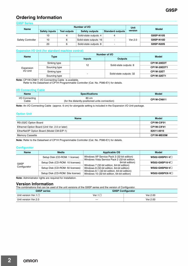
Ordering InformationG9SP Series
Expansion I/O Unit (for standard machine control)
Note: CP1W-CN811 I/O Connecting Cable is available.Refer to the Datasheet of CP1H Programmable Controller (Cat. No. P080-E1) for details.
I/O Connecting Cable
Note: An I/O Connecting Cable (approx. 6 cm) for alongside setting is included in the Expansion I/O Unit package.
Note: Administrator rights are required for installation.
Version InformationThe combinations that can be used of the unit versions of the G9SP series and the version of Configurator.
NameNumber of I/O Unit
version ModelSafety inputs Test outputs Safety outputs Standard outputs
Safety Controller
10 4 Solid-state outputs: 4 4
Ver.2.0
G9SP-N10S
10 6 Solid-state outputs: 16 - G9SP-N10D
20 6 Solid-state outputs: 8 - G9SP-N20S
Name TypeNumber of I/O
ModelInputs Outputs
Expansion I/O Unit
Sinking type12 Solid-state outputs: 8
CP1W-20EDT
Sourcing type CP1W-20EDT1
Sinking type- Solid-state outputs: 32
CP1W-32ET
Sourcing type CP1W-32ET1
Name Specifications Model
I/O Connecting Cable
80 cm(for the distantly-positioned units connection) CP1W-CN811
Name Media Applicable OS Model
G9SP Configurator
Setup Disk (CD-ROM: 1 license) Windows XP Service Pack 3 (32-bit edition)Windows Vista Service Pack 2 (32-bit edition,
64-bit edition)Windows 7 (32-bit edition, 64-bit edition)Windows 8 (32-bit edition, 64-bit edition)Windows 8.1 (32-bit edition, 64-bit edition)Windows 10 (32-bit edition, 64-bit edition)
WS02-G9SP01-V@
Setup Disk (CD-ROM: 10 licenses) WS02-G9SP10-V@
Setup Disk (CD-ROM: 50 licenses) WS02-G9SP50-V@
Setup Disk (CD-ROM: Site license) WS02-G9SPXX-V@
G9SP series G9SP Configurator
Unit version Ver.1.@ Ver.1.@ Ver.2.00
Unit version Ver.2.0 --- Ver.2.00
Configurator
Option UnitName Model
RS-232C Option Board CP1W-CIF01Ethernet Option Board (Unit Ver. 2.0 or later) CP1W-CIF41
Memory Cassette CP1W-ME05MEtherNet/IP Option Board (Model CM-EIP-1) 82611-0010
Note: Refer to the Datasheet of CP1H Programmable Controller (Cat. No. P080-E1) for details.
2
G9SP
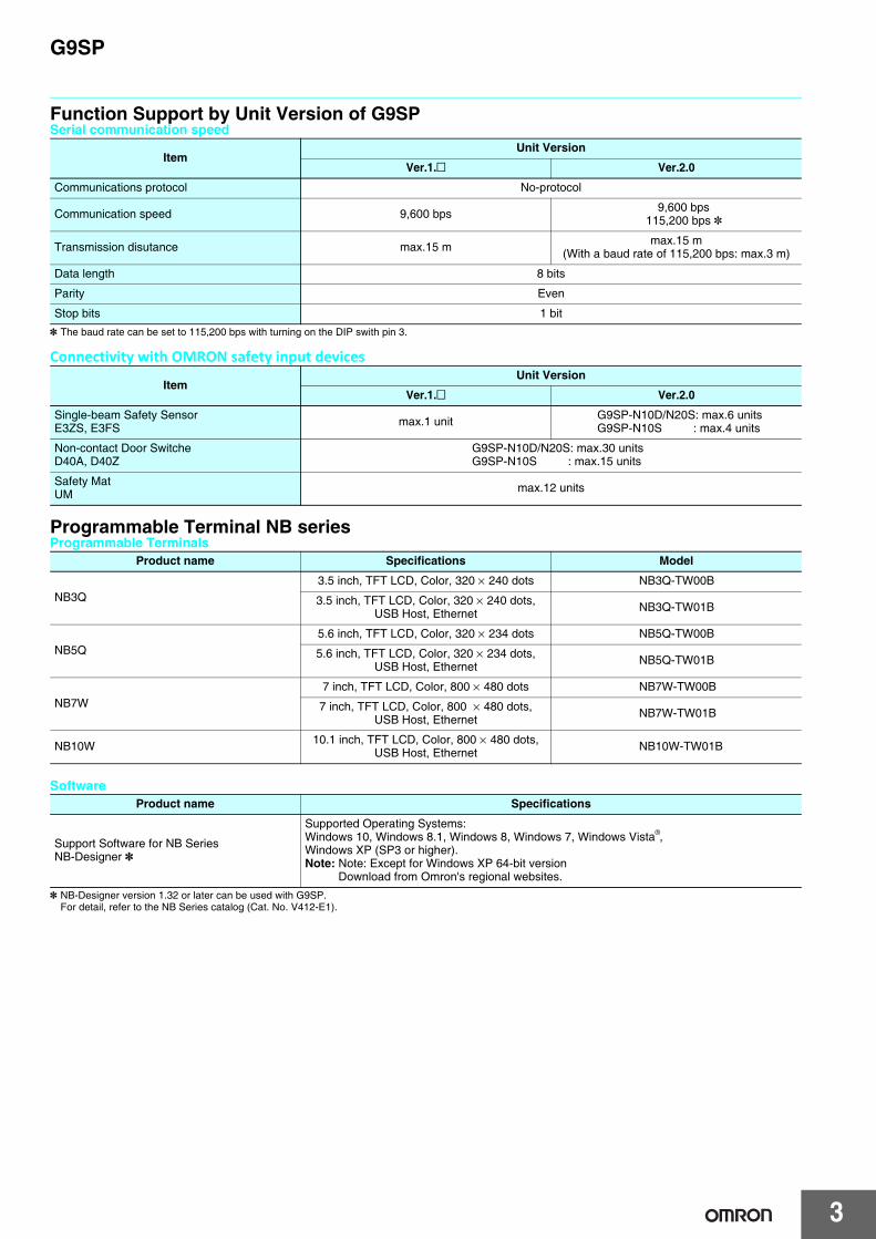
Function Support by Unit Version of G9SPSerial communication speed
* The baud rate can be set to 115,200 bps with turning on the DIP swith pin 3.
Connectivity with OMRON safety input devices
Programmable Terminal NB series Programmable Terminals
Software
* NB-Designer version 1.32 or later can be used with G9SP.For detail, refer to the NB Series catalog (Cat. No. V412-E1).
ItemUnit Version
Ver.1.@ Ver.2.0
Communications protocol No-protocol
Communication speed 9,600 bps 9,600 bps115,200 bps *
Transmission disutance max.15 m max.15 m(With a baud rate of 115,200 bps: max.3 m)
Data length 8 bits
Parity Even
Stop bits 1 bit
ItemUnit Version
Ver.1.@ Ver.2.0
Single-beam Safety SensorE3ZS, E3FS max.1 unit G9SP-N10D/N20S: max.6 units
G9SP-N10S : max.4 units
Non-contact Door SwitcheD40A, D40Z
G9SP-N10D/N20S: max.30 unitsG9SP-N10S : max.15 units
Safety MatUM max.12 units
Product name Specifications Model
NB3Q3.5 inch, TFT LCD, Color, 320 × 240 dots NB3Q-TW00B
3.5 inch, TFT LCD, Color, 320 × 240 dots, USB Host, Ethernet NB3Q-TW01B
NB5Q5.6 inch, TFT LCD, Color, 320 × 234 dots NB5Q-TW00B
5.6 inch, TFT LCD, Color, 320 × 234 dots, USB Host, Ethernet NB5Q-TW01B
NB7W7 inch, TFT LCD, Color, 800 × 480 dots NB7W-TW00B
7 inch, TFT LCD, Color, 800 × 480 dots, USB Host, Ethernet NB7W-TW01B
NB10W 10.1 inch, TFT LCD, Color, 800 × 480 dots, USB Host, Ethernet NB10W-TW01B
Product name Specifications
Support Software for NB SeriesNB-Designer *
Supported Operating Systems:Windows 10, Windows 8.1, Windows 8, Windows 7, Windows Vista , Windows XP (SP3 or higher).Note: Note: Except for Windows XP 64-bit version
Download from Omron's regional websites.
®
3
G9SP
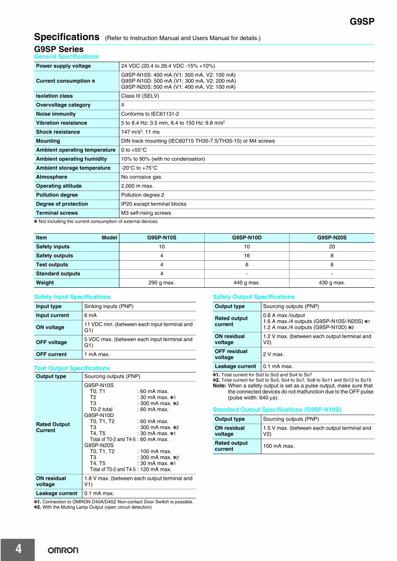
Specifications (Refer to Instruction Manual and Users Manual for details.)
G9SP SeriesGeneral Specifications
* Not including the current consumption of external devices.
Safety Input Specifications
Test Output Specifications
*1. Connection to OMRON D40A/D40Z Non-contact Door Switch is possible.*2. With the Muting Lamp Output (open circuit detection)
Safety Output Specifications
*1. Total current for So0 to So3 and So4 to So7*2. Total current for So0 to So3, So4 to So7, So8 to So11 and So12 to So15Note: When a safety output is set as a pulse output, make sure that
the connected devices do not malfunction due to the OFF pulse (pulse width: 640 μs).
Standard Output Specifications (G9SP-N10S)
Power supply voltage 24 VDC (20.4 to 26.4 VDC -15% +10%)
Current consumption *G9SP-N10S: 400 mA (V1: 300 mA, V2: 100 mA)G9SP-N10D: 500 mA (V1: 300 mA, V2: 200 mA)G9SP-N20S: 500 mA (V1: 400 mA, V2: 100 mA)
Isolation class Class III (SELV)
Overvoltage category II
Noise immunity Conforms to IEC61131-2
Vibration resistance 5 to 8.4 Hz: 3.5 mm, 8.4 to 150 Hz: 9.8 m/s2
Shock resistance 147 m/s2: 11 ms
Mounting DIN track mounting (IEC60715 TH35-7.5/TH35-15) or M4 screws
Ambient operating temperature 0 to +55°C
Ambient operating humidity 10% to 90% (with no condensation)
Ambient storage temperature -20°C to +75°C
Atmosphere No corrosive gas
Operating altitude 2,000 m max.
Pollution degree Pollution degree 2
Degree of protection IP20 except terminal blocks
Terminal screws M3 self-rising screws
Item Model G9SP-N10S G9SP-N10D G9SP-N20S
Safety inputs 10 10 20
Safety outputs 4 16 8
Test outputs 4 6 6
Standard outputs 4 - -
Weight 290 g max. 440 g max. 430 g max.
Input type Sinking inputs (PNP)
Input current 6 mA
ON voltage 11 VDC min. (between each input terminal and G1)
OFF voltage 5 VDC max. (between each input terminal and G1)
OFF current 1 mA max.
Output type Sourcing outputs (PNP)
Rated Output Current
G9SP-N10ST0, T1 : 60 mA max.T2 : 30 mA max. *1T3 : 300 mA max. *2T0-2 total : 60 mA max.
G9SP-N10DT0, T1, T2 : 60 mA max.T3 : 300 mA max. *2T4, T5 : 30 mA max. *1Total of T0-2 and T4-5 : 60 mA max.
G9SP-N20ST0, T1, T2 : 100 mA max.T3 : 300 mA max. *2T4, T5 : 30 mA max. *1Total of T0-2 and T4-5 : 120 mA max.
ON residual voltage
1.8 V max. (between each output terminal and V1)
Leakage current 0.1 mA max.
Output type Sourcing outputs (PNP)
Rated output current
0.8 A max./output1.6 A max./4 outputs (G9SP-N10S/-N20S) *11.2 A max./4 outputs (G9SP-N10D) *2
ON residual voltage
1.2 V max. (between each output terminal and V2)
OFF residual voltage 2 V max.
Leakage current 0.1 mA max.
Output type Sourcing outputs (PNP)
ON residual voltage
1.5 V max. (between each output terminal and V2)
Rated output current 100 mA max.
4
G9SP
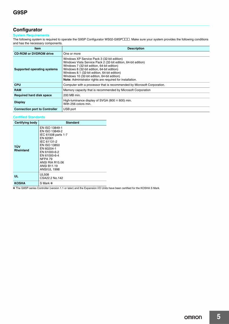
ConfiguratorSystem RequirementsThe following system is required to operate the G9SP Configurator WS02-G9SP@@@. Make sure your system provides the following conditions and has the necessary components.
Certified Standards
* The G9SP-series Controller (version 1.1 or later) and the Expansion I/O Units have been certified for the KOSHA S Mark.
Item Description
CD-ROM or DVDROM drive One or more
Supported operating systems
Windows XP Service Pack 3 (32-bit edition)Windows Vista Service Pack 2 (32-bit edition, 64-bit edition)Windows 7 (32-bit edition, 64-bit edition)Windows 8 (32-bit edition, 64-bit edition)Windows 8.1 (32-bit edition, 64-bit edition)Windows 10 (32-bit edition, 64-bit edition)Note: Administrator rights are required for installation.
CPU Computer with a processor that is recommended by Microsoft Corporation.
RAM Memory capacity that is recommended by Microsoft Corporation
Required hard disk space 200 MB min.
Display High-luminance display of SVGA (800 × 600) min.With 256 colors min.
Connection port to Controller USB port
Certifying body Standard
TÜVRheinland
EN ISO 13849-1EN ISO 13849-2IEC 61508 parts 1-7EN 62061IEC 61131-2EN ISO 13850EN 60204-1EN 61000-6-2EN 61000-6-4NFPA 79ANSI RIA R15.06ANSI B11.19ANSI/UL 1998
UL UL508CSA22.2 No.142
KOSHA S Mark *
5
G9SP
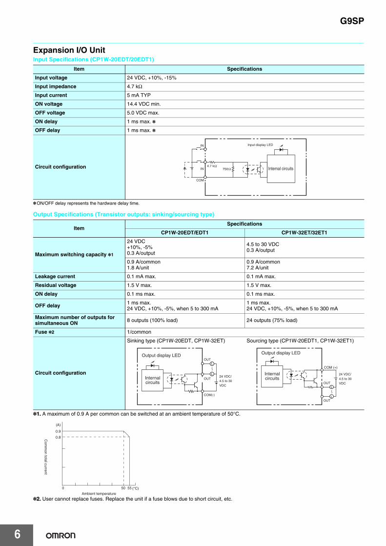
Expansion I/O UnitInput Specifications (CP1W-20EDT/20EDT1)
*ON/OFF delay represents the hardware delay time.
Output Specifications (Transistor outputs: sinking/sourcing type)
*1. A maximum of 0.9 A per common can be switched at an ambient temperature of 50°C.
*2. User cannot replace fuses. Replace the unit if a fuse blows due to short circuit, etc.
Item Specifications
Input voltage 24 VDC, +10%, -15%
Input impedance 4.7 kΩ
Input current 5 mA TYP
ON voltage 14.4 VDC min.
OFF voltage 5.0 VDC max.
ON delay 1 ms max. *
OFF delay 1 ms max. *
Circuit configuration
ItemSpecifications
CP1W-20EDT/EDT1 CP1W-32ET/32ET1
Maximum switching capacity *1
24 VDC+10%, -5%0.3 A/output
4.5 to 30 VDC 0.3 A/output
0.9 A/common1.8 A/unit
0.9 A/common7.2 A/unit
Leakage current 0.1 mA max. 0.1 mA max.
Residual voltage 1.5 V max. 1.5 V max.
ON delay 0.1 ms max. 0.1 ms max.
OFF delay 1 ms max.24 VDC, +10%, -5%, when 5 to 300 mA
1 ms max.24 VDC, +10%, -5%, when 5 to 300 mA
Maximum number of outputs for simultaneous ON 8 outputs (100% load) 24 outputs (75% load)
Fuse *2 1/common
Circuit configuration
Sinking type (CP1W-20EDT, CP1W-32ET) Sourcing type (CP1W-20EDT1, CP1W-32ET1)
IN
IN
COM
4.7 k
Input display LED
Internal circuits750
OUTL
LOUT
COM(-)
24 VDC/4.5 to 30 VDC
Output display LED
Internalcircuits
COM (+)
OUT
OUT
L
L
24 VDC/4.5 to 30 VDC
Output display LED
Internalcircuits
0.9
0.8
50 55
Ambient temperature
(A)
(°C)
Com
mon total current
0
6
G9SP
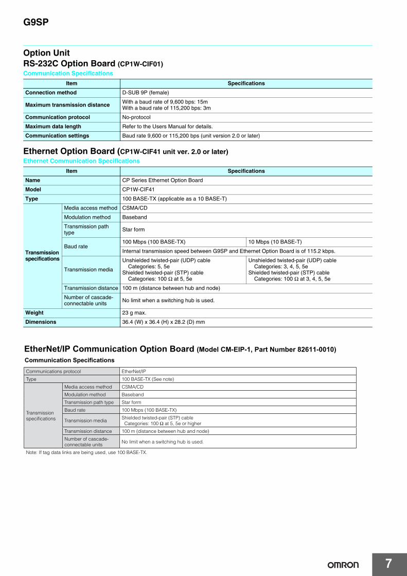
Option UnitRS-232C Option Board (CP1W-CIF01)Communication Specifications
Ethernet Option Board (CP1W-CIF41 unit ver. 2.0 or later)Ethernet Communication Specifications
Item Specifications
Connection method D-SUB 9P (female)
Maximum transmission distance With a baud rate of 9,600 bps: 15mWith a baud rate of 115,200 bps: 3m
Communication protocol No-protocol
Maximum data length Refer to the Users Manual for details.
Communication settings Baud rate 9,600 or 115,200 bps (unit version 2.0 or later)
Item Specifications
Name CP Series Ethernet Option Board
Model CP1W-CIF41
Type 100 BASE-TX (applicable as a 10 BASE-T)
Transmission specifications
Media access method CSMA/CD
Modulation method Baseband
Transmission path type Star form
Baud rate100 Mbps (100 BASE-TX) 10 Mbps (10 BASE-T)
Internal transmission speed between G9SP and Ethernet Option Board is of 115.2 kbps.
Transmission media
Unshielded twisted-pair (UDP) cableCategories: 5, 5e
Shielded twisted-pair (STP) cable Categories: 100 Ω at 5, 5e
Unshielded twisted-pair (UDP) cableCategories: 3, 4, 5, 5e
Shielded twisted-pair (STP) cableCategories: 100 Ω at 3, 4, 5, 5e
Transmission distance 100 m (distance between hub and node)
Number of cascade-connectable units No limit when a switching hub is used.
Weight 23 g max.
Dimensions 36.4 (W) x 36.4 (H) x 28.2 (D) mm
Communications protocol EtherNet/IP
Type 100 BASE-TX (See note)
Transmission specifications
Media access method CSMA/CD
Modulation method Baseband
Transmission path type Star form
Baud rate 100 Mbps (100 BASE-TX)
Transmission mediaShielded twisted-pair (STP) cable Categories: 100 Ω at 5, 5e or higher
Transmission distance 100 m (distance between hub and node)
Number of cascade-connectable units
No limit when a switching hub is used.
Note: If tag data links are being used, use 100 BASE-TX.
EtherNet/IP Communication Option Board (Model CM-EIP-1, Part Number 82611-0010) Communication Specifications
7

G9SP
Functions (Refer to the Instructions Reference Manual (Cat. No. Z923-E1) for details.)
Function BlocksLogic Functions
Timer/Counter Functions
Function Block Name
Notation on Function List Icon Details
NOT NOT Outputs the logical complement of the input condition.
AND AND Outputs the logical AND of the input conditions.
OR OR Outputs the logical OR of the input conditions.
NAND NAND Outputs the logical NAND of the input conditions.
NOR NOR Outputs the logical NOR of the input conditions.
Exclusive OR EXOR Outputs the exclusive OR of the input conditions.
Exclusive NOR EXNOR Outputs the exclusive NOR of the input conditions.
RS-FF(Reset Set Flip-Flop)
RS-FF When the input signal turns ON, RS-FF holds the ON status in the function block and continuously connects to the output.
Comparator Comparator Compares the input signals to the set value and turns ON the output if they match.
Comparator 2 Comparator2 Compares the input signals to the set value and outputs the comparison result.
Function Block Name
Notation on Function List Icon Details
Off-Delay Timer Off-Delay Timer Operates an OFF-delay timer.
On-Delay Timer On-Delay Timer Operates an ON-delay timer.
Pulse Generator Pulse Generator Cyclically outputs ON/OFF pulses on the Output Enable while the input signal is ON.
Counter Counter Counts the number of input signals and turns ON the output when the count reaches the specified number.
Up-Down Counter Up-DownCounter
Increments the counter on the leading edge of an up count input and decrements the counter on the leading edge of a down count input.
Serial-Parallel Converter
Serial-ParallelConverter Counts the number of input signals and outputs the count value.
8

G9SP
Safety Device Function Blocks
Reset and Restart Function Blocks
Connector Function Blocks
Function Block Name
Notation on Function List Icon Details
External Device Monitoring EDM
Evaluates the input signal and external device status and sends a safety output to the external device. This function block is used to detect fused contacts or external wiring problems (disconnected lines) for safety relays, contactors, and other safety devices.
Enable Switch Monitoring Enable Switch Monitors the status of an Enable Switch device.
Emergency Stop Switch Monitoring E-Stop Monitors the status of an Emergency Stop Switch.
Light Curtain Monitoring
Light Curtain Monitoring Monitors the input signal from a Safety Light Curtain.
Muting Muting Temporarily disables the input signals for a Light Curtain when the muting signal is detected.
Safety Gate Monitoring Safety Gate Monitoring
Monitors the status of a safety door (Safety-door Switch or Safety Limit Switch). This function block can be used to set function tests for Safety Category 2.
Two Hand Controller Two Hand Controller Monitors the status of a Two-hand Switch.
User Mode Switch Monitoring User Mode Switch Monitors the operating mode switch for a user system or device.
Redundant Input Monitoring Redundant Input Monitors for discrepancies in two input signals.
Single Beam Safety Sensor
Single BeamSafety Sensor
Monitors the input signal of an OMRON E3ZS/E3FS Single-beam Safety Sensor.
Non-Contact Door Switch Monitoring
Non-ContactDoor Switch Monitors an OMRON D40A/D40Z Non-contact Door Switch.
Safety Mat Monitoring Safety Mat Monitors an OMRON UM Safety Mat.
Function Block Name
Notation on Function List Icon Details
Reset ResetOutputs ON if the reset signal is correctly input while the input condition is ON. This function block can be used to prevent equipment from starting automatically.
Restart Restart Performs the same operation as a Reset function block. The icon is different.
Function Block Name
Notation on Function List Icon Details
Multi Connector Multi Connector Outputs the status of the input signals.
Routing Routing Distributes an input signal to multiple signals.
9
G9SP
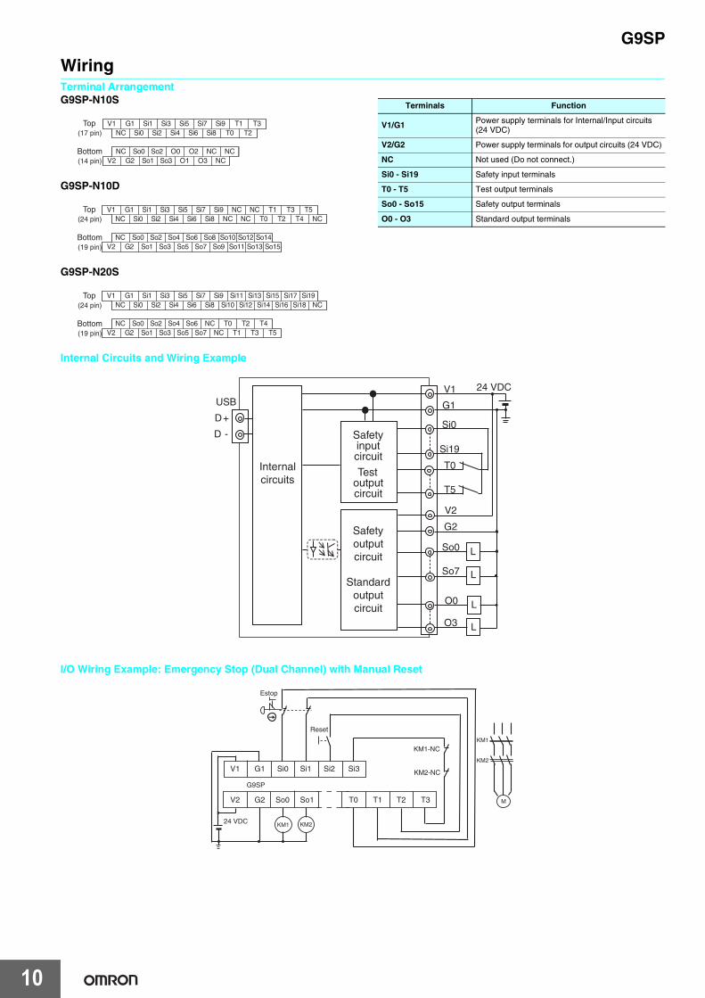
WiringTerminal ArrangementG9SP-N10S
G9SP-N10D
G9SP-N20S
Internal Circuits and Wiring Example
I/O Wiring Example: Emergency Stop (Dual Channel) with Manual Reset
NC
NC NC
Si0Si1
O0
Si2Si3
Si4Si5
Si6Si7
Si8Si9
V2
V1 G1
So1So2
So3
T0T1 T3Top
(17 pin)
Bottom(14 pin) G2
So0NC
NCO1
O2O3
T2
Top(24 pin)
Bottom(19 pin)
NC NCSi0
So8
Si1
So9
Si2
So10
Si3
So11
Si4
So12
Si5
So13
Si6
So14
Si7
So15
Si8Si9
V2
V1 G1
So1So2
So3
NCNC
T0
So7So4
So5So6
T1
G2So0NC
NCNC
T2T3
T4T5
Top(24 pin)
Bottom(19 pin)
NC
NC
NCSi0Si1
Si2Si3
Si4Si5
Si6Si7
Si8Si9
Si10Si11
Si12Si13
Si14Si15
Si16Si17
Si18
V2
V1 G1
T0T1
T2
Si19
So0G2 So1
So2So3
So4So5
So6So7
NCNC T3
T4T5
Terminals Function
V1/G1 Power supply terminals for Internal/Input circuits (24 VDC)
V2/G2 Power supply terminals for output circuits (24 VDC)
NC Not used (Do not connect.)
Si0 - Si19 Safety input terminals
T0 - T5 Test output terminals
So0 - So15 Safety output terminals
O0 - O3 Standard output terminals
D+
D -
USB
Internalcircuits
24 VDCV1
G1
Si0
Si19
T0
T5
V2
G2
So0
So7
O0
O3
L
L
L
L
Testoutputcircuit
Safetyinputcircuit
Standardoutputcircuit
Safetyoutputcircuit
24 VDC
V1
V2
G1
G2
Si0
So0
Si1
So1 T1 T2 T3
Si2 Si3
KM1-NC
KM2-NC
KM1 KM2
Reset
Estop
M
KM1
KM2
G9SP
T0
10
G9SP
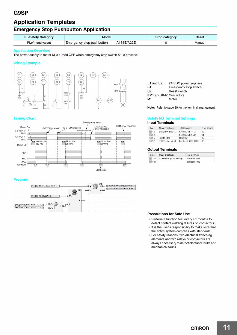
Application TemplatesEmergency Stop Pushbutton Application
Application OverviewThe power supply to motor M is turned OFF when emergency stop switch S1 is pressed.
Wiring Example
Program
PL/Safety Category Model Stop category Reset
PLe/4 equivalent Emergency stop pushbutton A165E/A22E 0 Manual
E1 and E2: 24-VDC power suppliesS1: Emergency stop switchS2: Reset switchKM1 and KM2:ContactorsM: Motor
Note: Refer to page 20 for the terminal arrangement.
Timing Chart
KM1
KM2
EDMfeedback
E-STOP pushed
More than 350 ms
E-STOP S111-12
Reset ON
E-STOP S121-22
Reset S2
More than 350 ms
E-STOP released
Discrepancy error
Discrepancyerror released
EDM error released
EDM error
More than 350 ms
Safety I/O Terminal SettingsInput Terminals
Output Terminals
Precautions for Safe Use• Perform a function test every six months to
detect contact welding failures on contactors.• It is the user's responsibility to make sure that
the entire system complies with standards.• For safety reasons, two electrical switching
elements and two relays or contactors arealways necessary to detect electrical faults andmechanical faults.
11
G9SP
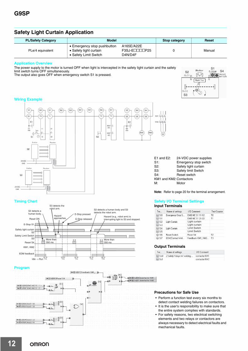
Safety Light Curtain Application
Application OverviewThe power supply to the motor is turned OFF when light is intercepted in the safety light curtain and the safety limit switch turns OFF simultaneously.The output also goes OFF when emergency switch S1 is pressed.
Wiring Example
Program
PL/Safety Category Model Stop category Reset
PLe/4 equivalent• Emergency stop pushbutton A165E/A22E• Safety light curtain F3SJ-E@@@@P25• Safety Limit Switch D4N/D4F
0 Manual
S1S2
S3
S4
E1 and E2: 24-VDC power suppliesS1: Emergency stop switchS2: Safety light curtainS3: Safety limit SwitchS4: Reset switchKM1 and KM2:ContactorsM: Motor
Note: Refer to page 20 for the terminal arrangement.
Timing Chart
Hazardapproaches.
S2 detects ahuman body.
Reset ON
E-Stop S1
Safety light curtainS2
Safety Limit SwitchS3
Reset S4
EDM feedback
KM1, KM2
Idle → Run
More than 350 ms
More than 350 ms
S2 detects a human body and S3 detects the robot arm.
E-Stop released
E-Stop pressed
S3 detects therobot arm.
Hazard (e.g., robot arm) is interrupting light to S3 and stopped.
Safety I/O Terminal SettingsInput Terminals
Output Terminals
Light curtainLight curtain
Limit SwitchLimit Switch
Precautions for Safe Use• Perform a function test every six months to
detect contact welding failures on contactors.• It is the user's responsibility to make sure that
the entire system complies with standards.• For safety reasons, two electrical switching
elements and two relays or contactors arealways necessary to detect electrical faults andmechanical faults.
12
G9SP
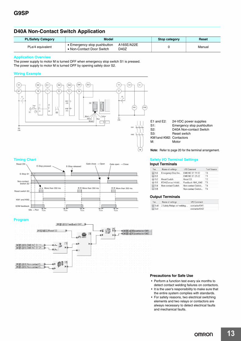
D40A Non-Contact Switch Application
Application OverviewThe power supply to motor M is turned OFF when emergency stop switch S1 is pressed.The power supply to motor M is turned OFF by opening safety door S2.
Wiring Example
Program
PL/Safety Category Model Stop category Reset
PLe/4 equivalent• Emergency stop pushbutton A165E/A22E• Non-Contact Door Switch D40Z
0 Manual
E1 and E2: 24-VDC power suppliesS1: Emergency stop pushbuttonS2: D40A Non-contact SwitchS3: Reset switchKM1and KM2: ContactorsM: Motor
Note: Refer to page 20 for the terminal arrangement.
Timing Chart
More than 350 ms More than 350 ms More than 350 ms
Idle → Run
Reset ONE-Stop pressed E-Stop released
Gate close → Open Gate open → Close
E-Stop S1
Non-contact Switch S2
Reset switch S3
KM1 and KM2
EDM feedback
Safety I/O Terminal SettingsInput Terminals
Output Terminals
Precautions for Safe Use• Perform a function test every six months to
detect contact welding failures on contactors.• It is the user's responsibility to make sure that
the entire system complies with standards.• For safety reasons, two electrical switching
elements and two relays or contactors arealways necessary to detect electrical faultsand mechanical faults.
13
G9SP
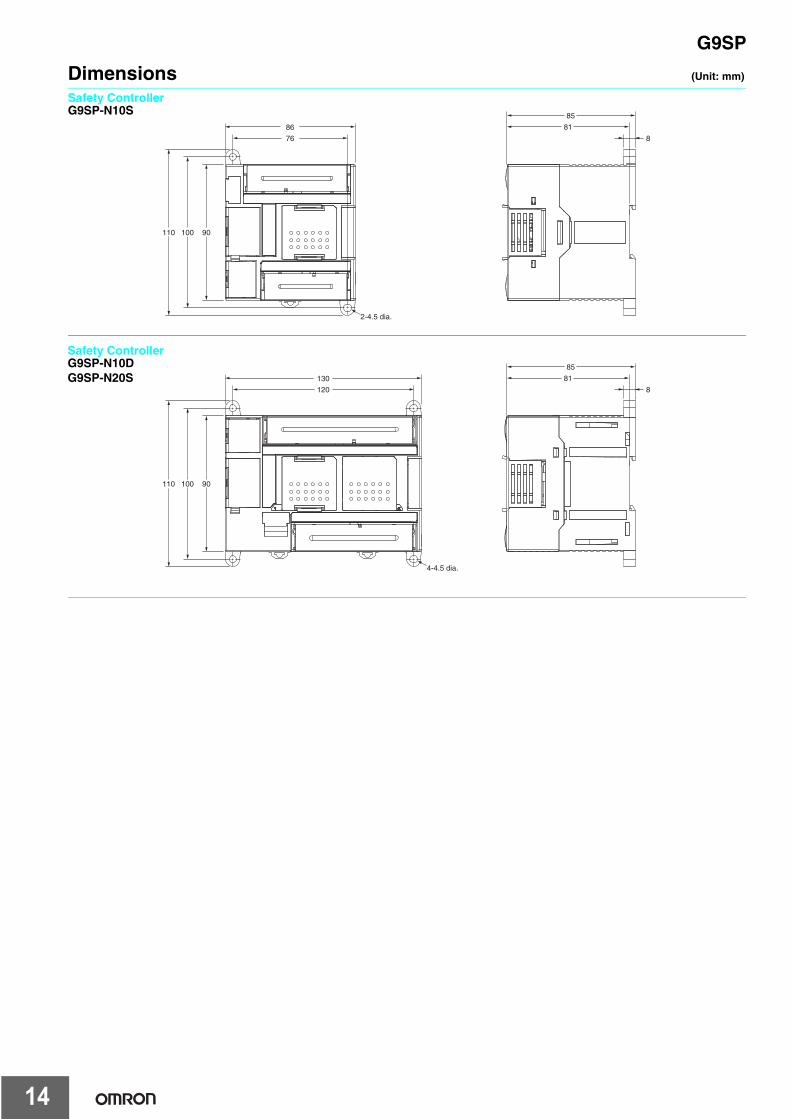
Dimensions (Unit: mm)
Safety ControllerG9SP-N10S
8
81
85
86
76
90100110
2-4.5 dia.
8
81
85
130
120
90100110
4-4.5 dia.
Safety ControllerG9SP-N10DG9SP-N20S
14

G9SP
Safety PrecautionsMeanings of Signal Words
Meaning of Alert Symbols
Electric shock may occur. Do not touch any terminals while power is being supplied.
Serious injury may possibly occur due to loss of required safety functions. Do not use the G9SP-series Controller's test outputs or standard outputs as safety outputs.
Serious injury may possibly occur due to loss of required safety functions. Do not use the G9SP-series Controller's network data as safety data.
Serious injury may possibly occur due to loss of required safety functions. Do not use indicators on the G9SP-series Controller for safety operations.
Serious injury may possibly occur due to breakdown of safety outputs or test outputs. Do not connect loads beyond the rated values to the safety outputs and test outputs.
Serious injury may possibly occur due to loss of required safety functions. Wire the G9SP-series Controller properly so that the 24 VDC line does NOT touch the outputs accidentally or unintentionally.
Serious injury may possibly occur due to loss of required safety functions. Ground the 0V line of the power supply for external output devices so that the devices do NOT turn ON when the safety output line or the test output line is grounded.
Serious injury may possibly occur due to loss of required safety functions. Perform user testing and confirm that all of the G9SP-series Controller’s configuration data and operation is correct before starting system operation.
Serious injury may possibly occur due to loss of required safety functions. When replacing a G9SP-series Controller, confirm the model of the Controller is correct and configure the replacement Controller suitably and confirm that it operates correctly.
Serious injury may possibly occur due to loss of required safety functions. When the configuration data is restored by using a Memory Cassette, a test must be performed to confirm that the safety devices function correctly.
Outputs may operate, possibly resulting in serious injury. Take sufficient safety measures before force-setting or force-resetting variables in the program.
Serious injury may possibly occur due to loss of required safety functions. Use devices and parts related to safety functions according to legal regulations in the applicable country. Use certified items compliant with safety standards corresponding to the intended application.
Handle with CareDo not drop the G9SP-series Controller or subject it to excessive vibration or mechanical shock. The G9SP-series Controller may be damaged and may not function properly.
Installation and Storage EnvironmentDo not use or store the G9SP-series Controller in any of the following locations:
• Locations subject to direct sunlight• Locations subject to temperatures or humidity outside the range
specified in the specifications• Locations subject to condensation as the result of severe chang-
es in temperature• Locations subject to corrosive or flammable gases• Locations subject to dust (especially iron dust) or salts• Locations subject to water, oil, or chemicals• Locations subject to shock or vibration
Take appropriate and sufficient measures when installing systems in the following locations. Inappropriate and insufficient measures may result in malfunction.
• Locations subject to static electricity or other forms of noise• Locations subject to strong electromagnetic fields• Locations subject to possible exposure to radioactivity• Locations close to power supplies
This is a class A product designed for use in industrial environments. In residential areas it may cause radio interference, in which case the user may be required to take adequate measures to reduce interference.• Use the G9SP-series Controller within an enclosure with IP54
protection or higher according to IEC/EN 60529.
Indicates a potentially hazardous situation which, if not avoided, will result in minor or moderate injury, or may result in serious injury or death. Additionally there may be significant property damage.
Indicates a potentially hazardous situation which, if not avoided, will result in minor or moderate injury, or there may be property damage.
Indicates prohibited actions.
Indicates mandatory actions.
WARNING
WARNING
CAUTION
Precautions for Safe Use
15

G9SP
• Use DIN Track (TH35-7.5/TH35-15 according to IEC 60715) or M4 screws with a tightening torque of 1.2 N·m (10.5 lb·in) to install the G9SP-series Controller into the control panel.
• Mount the G9SP-series Controller to the DIN Track using PFP-MEnd Plates (not included with the G9SP-series Controller) toprevent it from falling off the DIN Track because of vibration.Correctly mount all Units to DIN Track.
• Install the G9SP-series Controller in the vertical direction shownbelow to ensure adequate cooling.
• Space must be provided around the G9SP-series Controller, atleast 20 mm from its side surfaces and at least 50 mm from its top and bottom surfaces, for ventilation and wiring.
• Be sure to lock all locking mechanisms, such as those on I/Oterminal blocks and connectors, before attempting to use theController.
Turn OFF the power supply before performing any of the following.• Connecting or disconnecting Expansion I/O Units, Option Boards,
or any other Units• Assembling the Controller• Connecting cables or wiring• Connecting or removing terminal blocks
Installation and Wiring• Use the following to wire external I/O devices to the G9SP-series
Controller.
*When wiring two wires to one terminal. Use two wires of the same type and thickness.
• Tighten the terminal block screws to a torque of 0.5 N·m.• Disconnect the G9SP-series Controller from the power supply
before starting wiring. Devices connected to the G9SP-seriesController may operate unexpectedly.
• Properly apply the specified voltage to the G9SP-series Controller inputs. Applying an inappropriate DC voltage or any AC voltage will cause the G9SP-series Controller to fail.
• Be sure to separate the communications cables and I/O cablesfrom high-voltage/high-current lines.
• Be cautious not to get your fingers caught when attachingconnectors to the plugs on the G9SP-series Controller.
• Incorrect wiring may lead to loss of safety functions. Wireconductors correctly and verify the operation of the G9SP-seriesController before using the system in which the G9SP-seriesController is incorporated.
• Lock the connectors on Option Units or Expansion I/O Unit beforeusing the Units.
• After wiring is completed, be sure to remove the label for wire clipentry prevention from the G9SP-series Controller to enable heat to escape for proper cooling.
• Do not ground the 24-V side of the power supply to the G9SP-series Controller. If you do so, an unwanted current flow shown inthe following diagram may occur when you connect a computer or other peripheral device.
• Do not connect the Expansion I/O Units over the specified number.
Power Supply SelectionUse a DC power supply satisfying the following requirements.
• The secondary circuit of the DC power supply must be isolatedfrom the primary circuit by double insulation or reinforced insula-tion.
• The isolated power supply with a current limited to 8 A.• The output hold time must be 20 ms or longer.• The DC power supply must be an SELV power supply that sat-
isfies the requirements of IEC/EN 60950-1 and EN 50178.
Periodic Inspections and Maintenance• Disconnect the G9SP-series Controller from the power supply
before replacing the Controller. Devices connected to the G9SP-series Controller may operate unexpectedly.
• Do not disassemble, repair, or modify the G9SP-series Controller. Doing so may lead to loss of safety functions.
Disposal• Be cautious not to injure yourself when dismantling the G9SP-
series Controller.
Solid wire 0.32 to 0.82 mm2 AWG22 to AWG180.32 to 0.5 mm2 AWG22 to AWG20 *
Stranded wire 0.5 to 1.3 mm2 AWG20 to AWG160.5 to 0.82 mm2 AWG20 to AWG18 *
DC power circuit
24 V
0 V 0 V 0 V
G9SP Peripheral device
GND
USB cable
FG
16

Terms and Conditions of Sale1. Offer; Acceptance. These terms and conditions (these "Terms") are deemed
part of all quotes, agreements, purchase orders, acknowledgments, price lists,catalogs, manuals, brochures and other documents, whether electronic or inwriting, relating to the sale of products or services (collectively, the "Products")by Omron Electronics LLC and its subsidiary companies (“Omron”). Omronobjects to any terms or conditions proposed in Buyer’s purchase order or otherdocuments which are inconsistent with, or in addition to, these Terms.
2. Prices; Payment Terms. All prices stated are current, subject to change with-out notice by Omron. Omron reserves the right to increase or decrease priceson any unshipped portions of outstanding orders. Payments for Products aredue net 30 days unless otherwise stated in the invoice.
3. Discounts. Cash discounts, if any, will apply only on the net amount of invoicessent to Buyer after deducting transportation charges, taxes and duties, and willbe allowed only if (i) the invoice is paid according to Omron’s payment termsand (ii) Buyer has no past due amounts.
4. Interest. Omron, at its option, may charge Buyer 1-1/2% interest per month orthe maximum legal rate, whichever is less, on any balance not paid within thestated terms.
5. Orders. Omron will accept no order less than $200 net billing.6. Governmental Approvals. Buyer shall be responsible for, and shall bear all
costs involved in, obtaining any government approvals required for the impor-tation or sale of the Products.
7. Taxes. All taxes, duties and other governmental charges (other than generalreal property and income taxes), including any interest or penalties thereon,imposed directly or indirectly on Omron or required to be collected directly orindirectly by Omron for the manufacture, production, sale, delivery, importa-tion, consumption or use of the Products sold hereunder (including customsduties and sales, excise, use, turnover and license taxes) shall be charged toand remitted by Buyer to Omron.
8. Financial. If the financial position of Buyer at any time becomes unsatisfactoryto Omron, Omron reserves the right to stop shipments or require satisfactorysecurity or payment in advance. If Buyer fails to make payment or otherwisecomply with these Terms or any related agreement, Omron may (without liabil-ity and in addition to other remedies) cancel any unshipped portion of Prod-ucts sold hereunder and stop any Products in transit until Buyer pays allamounts, including amounts payable hereunder, whether or not then due,which are owing to it by Buyer. Buyer shall in any event remain liable for allunpaid accounts.
9. Cancellation; Etc. Orders are not subject to rescheduling or cancellationunless Buyer indemnifies Omron against all related costs or expenses.
10. Force Majeure. Omron shall not be liable for any delay or failure in deliveryresulting from causes beyond its control, including earthquakes, fires, floods,strikes or other labor disputes, shortage of labor or materials, accidents tomachinery, acts of sabotage, riots, delay in or lack of transportation or therequirements of any government authority.
11. Shipping; Delivery. Unless otherwise expressly agreed in writing by Omron:a. Shipments shall be by a carrier selected by Omron; Omron will not drop ship
except in “break down” situations.b. Such carrier shall act as the agent of Buyer and delivery to such carrier shall
constitute delivery to Buyer;c. All sales and shipments of Products shall be FOB shipping point (unless oth-
erwise stated in writing by Omron), at which point title and risk of loss shallpass from Omron to Buyer; provided that Omron shall retain a security inter-est in the Products until the full purchase price is paid;
d. Delivery and shipping dates are estimates only; ande. Omron will package Products as it deems proper for protection against nor-
mal handling and extra charges apply to special conditions.12. Claims. Any claim by Buyer against Omron for shortage or damage to the
Products occurring before delivery to the carrier must be presented in writingto Omron within 30 days of receipt of shipment and include the original trans-portation bill signed by the carrier noting that the carrier received the Productsfrom Omron in the condition claimed.
13. Warranties. (a) Exclusive Warranty. Omron’s exclusive warranty is that theProducts will be free from defects in materials and workmanship for a period oftwelve months from the date of sale by Omron (or such other period expressedin writing by Omron). Omron disclaims all other warranties, express or implied.(b) Limitations. OMRON MAKES NO WARRANTY OR REPRESENTATION,EXPRESS OR IMPLIED, ABOUT NON-INFRINGEMENT, MERCHANTABIL-
ITY OR FITNESS FOR A PARTICULAR PURPOSE OF THE PRODUCTS.BUYER ACKNOWLEDGES THAT IT ALONE HAS DETERMINED THAT THEPRODUCTS WILL SUITABLY MEET THE REQUIREMENTS OF THEIRINTENDED USE. Omron further disclaims all warranties and responsibility ofany type for claims or expenses based on infringement by the Products or oth-erwise of any intellectual property right. (c) Buyer Remedy. Omron’s sole obli-gation hereunder shall be, at Omron’s election, to (i) replace (in the formoriginally shipped with Buyer responsible for labor charges for removal orreplacement thereof) the non-complying Product, (ii) repair the non-complyingProduct, or (iii) repay or credit Buyer an amount equal to the purchase price ofthe non-complying Product; provided that in no event shall Omron be responsi-ble for warranty, repair, indemnity or any other claims or expenses regardingthe Products unless Omron’s analysis confirms that the Products were prop-erly handled, stored, installed and maintained and not subject to contamina-tion, abuse, misuse or inappropriate modification. Return of any Products byBuyer must be approved in writing by Omron before shipment. Omron Compa-nies shall not be liable for the suitability or unsuitability or the results from theuse of Products in combination with any electrical or electronic components,circuits, system assemblies or any other materials or substances or environ-ments. Any advice, recommendations or information given orally or in writing,are not to be construed as an amendment or addition to the above warranty.See http://www.omron247.com or contact your Omron representative for pub-lished information.
14. Limitation on Liability; Etc. OMRON COMPANIES SHALL NOT BE LIABLEFOR SPECIAL, INDIRECT, INCIDENTAL, OR CONSEQUENTIAL DAMAGES,LOSS OF PROFITS OR PRODUCTION OR COMMERCIAL LOSS IN ANYWAY CONNECTED WITH THE PRODUCTS, WHETHER SUCH CLAIM ISBASED IN CONTRACT, WARRANTY, NEGLIGENCE OR STRICT LIABILITY.Further, in no event shall liability of Omron Companies exceed the individualprice of the Product on which liability is asserted.
15. Indemnities. Buyer shall indemnify and hold harmless Omron Companies andtheir employees from and against all liabilities, losses, claims, costs andexpenses (including attorney's fees and expenses) related to any claim, inves-tigation, litigation or proceeding (whether or not Omron is a party) which arisesor is alleged to arise from Buyer's acts or omissions under these Terms or inany way with respect to the Products. Without limiting the foregoing, Buyer (atits own expense) shall indemnify and hold harmless Omron and defend or set-tle any action brought against such Companies to the extent based on a claimthat any Product made to Buyer specifications infringed intellectual propertyrights of another party.
16. Property; Confidentiality. Any intellectual property in the Products is the exclu-sive property of Omron Companies and Buyer shall not attempt to duplicate itin any way without the written permission of Omron. Notwithstanding anycharges to Buyer for engineering or tooling, all engineering and tooling shallremain the exclusive property of Omron. All information and materials suppliedby Omron to Buyer relating to the Products are confidential and proprietary,and Buyer shall limit distribution thereof to its trusted employees and strictlyprevent disclosure to any third party.
17. Export Controls. Buyer shall comply with all applicable laws, regulations andlicenses regarding (i) export of products or information; (iii) sale of products to“forbidden” or other proscribed persons; and (ii) disclosure to non-citizens ofregulated technology or information.
18. Miscellaneous. (a) Waiver. No failure or delay by Omron in exercising any rightand no course of dealing between Buyer and Omron shall operate as a waiverof rights by Omron. (b) Assignment. Buyer may not assign its rights hereunderwithout Omron's written consent. (c) Law. These Terms are governed by thelaw of the jurisdiction of the home office of the Omron company from whichBuyer is purchasing the Products (without regard to conflict of law princi-ples). (d) Amendment. These Terms constitute the entire agreement betweenBuyer and Omron relating to the Products, and no provision may be changedor waived unless in writing signed by the parties. (e) Severability. If any provi-sion hereof is rendered ineffective or invalid, such provision shall not invalidateany other provision. (f) Setoff. Buyer shall have no right to set off any amountsagainst the amount owing in respect of this invoice. (g) Definitions. As usedherein, “including” means “including without limitation”; and “Omron Compa-nies” (or similar words) mean Omron Corporation and any direct or indirectsubsidiary or affiliate thereof.
Certain Precautions on Specifications and Use1. Suitability of Use. Omron Companies shall not be responsible for conformity
with any standards, codes or regulations which apply to the combination of theProduct in the Buyer’s application or use of the Product. At Buyer’s request,Omron will provide applicable third party certification documents identifyingratings and limitations of use which apply to the Product. This information byitself is not sufficient for a complete determination of the suitability of the Prod-uct in combination with the end product, machine, system, or other applicationor use. Buyer shall be solely responsible for determining appropriateness ofthe particular Product with respect to Buyer’s application, product or system.Buyer shall take application responsibility in all cases but the following is anon-exhaustive list of applications for which particular attention must be given:(i) Outdoor use, uses involving potential chemical contamination or electricalinterference, or conditions or uses not described in this document.(ii) Use in consumer products or any use in significant quantities.(iii) Energy control systems, combustion systems, railroad systems, aviationsystems, medical equipment, amusement machines, vehicles, safety equip-ment, and installations subject to separate industry or government regulations. (iv) Systems, machines and equipment that could present a risk to life or prop-erty. Please know and observe all prohibitions of use applicable to this Prod-uct. NEVER USE THE PRODUCT FOR AN APPLICATION INVOLVING SERIOUSRISK TO LIFE OR PROPERTY OR IN LARGE QUANTITIES WITHOUTENSURING THAT THE SYSTEM AS A WHOLE HAS BEEN DESIGNED TO
ADDRESS THE RISKS, AND THAT THE OMRON’S PRODUCT IS PROP-ERLY RATED AND INSTALLED FOR THE INTENDED USE WITHIN THEOVERALL EQUIPMENT OR SYSTEM.
2. Programmable Products. Omron Companies shall not be responsible for theuser’s programming of a programmable Product, or any consequence thereof.
3. Performance Data. Data presented in Omron Company websites, catalogsand other materials is provided as a guide for the user in determining suitabil-ity and does not constitute a warranty. It may represent the result of Omron’stest conditions, and the user must correlate it to actual application require-ments. Actual performance is subject to the Omron’s Warranty and Limitationsof Liability.
4. Change in Specifications. Product specifications and accessories may bechanged at any time based on improvements and other reasons. It is our prac-tice to change part numbers when published ratings or features are changed,or when significant construction changes are made. However, some specifica-tions of the Product may be changed without any notice. When in doubt, spe-cial part numbers may be assigned to fix or establish key specifications foryour application. Please consult with your Omron’s representative at any timeto confirm actual specifications of purchased Product.
5. Errors and Omissions. Information presented by Omron Companies has beenchecked and is believed to be accurate; however, no responsibility is assumedfor clerical, typographical or proofreading errors or omissions.

OMRON CANADA, INC. • HEAD OFFICEToronto, ON, Canada • 416.286.6465 • 866.986.6766 • www.omron247.com
OMRON ELECTRONICS DE MEXICO • HEAD OFFICEMéxico DF • 52.55.59.01.43.00 • 01-800-226-6766 • [email protected]
OMRON ELECTRONICS DE MEXICO • SALES OFFICEApodaca, N.L. • 52.81.11.56.99.20 • 01-800-226-6766 • [email protected]
OMRON ELETRÔNICA DO BRASIL LTDA • HEAD OFFICESão Paulo, SP, Brasil • 55.11.2101.6300 • www.omron.com.br
OMRON ARGENTINA • SALES OFFICECono Sur • 54.11.4783.5300
OMRON CHILE • SALES OFFICESantiago • 56.9.9917.3920
OTHER OMRON LATIN AMERICA SALES54.11.4783.5300
Authorized Distributor:
F42I-E-03 01/17 Note: Specifications are subject to change. © 2017 Omron. All Rights Reserved. Printed in U.S.A.
Printed on recycled paper.
OMRON AUTOMATION AMERICAS HEADQUARTERS • Chicago, IL USA • 847.843.7900 • 800.556.6766 • www.omron247.com
OMRON EUROPE B.V. • Wegalaan 67-69, NL-2132 JD, Hoofddorp, The Netherlands. • +31 (0) 23 568 13 00 • www.industrial.omron.eu
Controllers & I/O • Machine Automation Controllers (MAC) • Motion Controllers • Programmable Logic Controllers (PLC) • Temperature Controllers • Remote I/O
Robotics • Industrial Robots • Mobile Robots
Operator Interfaces• Human Machine Interface (HMI)
Motion & Drives• Machine Automation Controllers (MAC) • Motion Controllers • Servo Systems • Frequency Inverters
Vision, Measurement & Identification• Vision Sensors & Systems • Measurement Sensors • Auto Identification Systems
Sensing• Photoelectric Sensors • Fiber-Optic Sensors • Proximity Sensors • Rotary Encoders • Ultrasonic Sensors
Safety • Safety Light Curtains • Safety Laser Scanners • Programmable Safety Systems • Safety Mats and Edges • Safety Door Switches • Emergency Stop Devices • Safety Switches & Operator Controls • Safety Monitoring/Force-guided Relays
Control Components • Power Supplies • Timers • Counters • Programmable Relays • Digital Panel Meters • Monitoring Products
Switches & Relays • Limit Switches • Pushbutton Switches • Electromechanical Relays • Solid State Relays
Software • Programming & Configuration • Runtime