Embed Size (px)
Citation preview
G650
Generator Protection & Control System
Gen
erat
or P
rote
ctio
n
• Complete distributed generator interconnection protection with two protection options, Basic Protection and Enhanced Protection, to fit your generator protection requirements.
• Preconfigured with Logic for standard Tripping and Closing operation.
• Reduce installation space requirements with a compact design incorporating protection, control, programmable pushbuttons, programmable LEDs, and communication interfaces
• Reduced system event analyzing time and cost through integrated Sequence of Event reports, Oscillography recording, and Trending files.
• Flexible and cost effective control for complex systems through the use of IEC61131 compatible programmable logic to customize the relay’s operation
• Minimized communication down time through reliable redundant Ethernet Communication ports
• Protection of small to medium sized Induction or Synchronous Generators
• Stand-alone or component in automated substation control system
• Distributed generation and interconnection protection, management, and control where programmable logic is a requirement to interact with prime mover control system
• Current, voltage, power, power factor, frequency metering, demand
• Breaker condition monitoring including breaker arcing current (I2t) trip counters, and trip circuit monitoring
• Event Recorder - 479 time tagged events, with 1ms time resolution
• High resolution oscillography and Data Logger, with programmable sampling rate
• Fault locator, record of last 10 faults
Monitoring and MeteringBasic Protection Option• Phase, Neutral, Ground and Negative Sequence TOC and
IOC
• Neutral and Ground Directional Overcurrent
• Voltage Restraint Overcurrent
• Phase Under and Overvoltage, Neutral and Ground Overvoltage
• Directional Power
• Under and Overfrequency, and Frequency Rate of Change
• Generator Thermal Model
• Generator Current unbalance
• Loss of Excitation
• Inadvertent Generator Energization
Communications• Standard serial interface with RS232 , optional USB port - up
to 115,200 bps• Optional second rear RS485 or serial fiber plastic or glass fiber
optic port• Ethernet Ports – 10/100 Base TX, 100 Base FX with ST
connectors, options for redundancy available• Multiple protocols - ModBus™ RTU and over TCP/IP, DNP 3.0
Level 2, IEC 60870-5-104, Http, and tftp.
Enhanced Protection Option (Includes all Basic functions)
• Sensitive Ground Overcurrent
• Volts/Hz
• Power Factor limiting
• Vector surge loss of mains detection
• Breaker Failure
• VT Fuse failure
• Restricted Ground Fault
Protection, control and monitoring for generator interconnection
FEATURES
APPLICATIOnS
KEy BEnEFITS
EnerVistaTM Software• State of the art software for configuration and commissioning
GE Multilin products• Document and software archiving toolset to ensure reference
material and device utilities are up-to-date• EnerVistaTM Integrator providing easy integration of data in the
G650 into new or existing monitoring and control systems
109g MultilinDigital Energy
G650GEnERATOR PROTECTIOn &
COnTROL SySTEM
G650 Generator Protection & Control SystemG
ener
ator
Pro
tect
ion Protection and Control
The G650 is a distributed generation protection and control system designed to protect and control small to medium size generators, as well as to operate as a distributed generation interconnection protection system. All the elements required by international standards to protect a distributed generator have been integrated into a single package for a cost-effective, reliable and simple solution. Additionally, the enhance fault recording and communications capability found in the G650 truly make this relay a global leader in the Generator Interconnect marketplace. As part of the 650 Family, the G650 provides superior protection and control that includes:
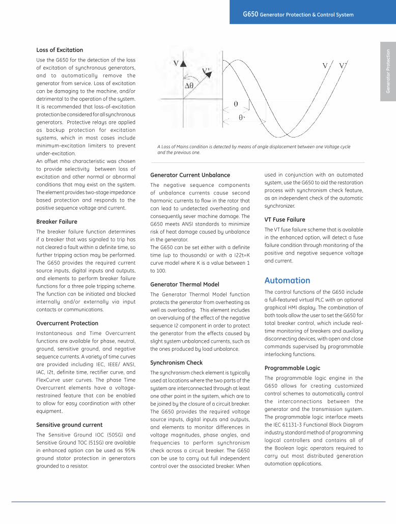
Loss of Mains
The Loss of Mains element has a fast decoupling time that can be used to protect synchronous generators in case of a mains failure. The angle displacement setting is selectable between 2 and 22º.The Loss of Mains Element may be applied in two different operating modes:
• TriptheGeneratorbreakerincasesoffailure in the interconnecting feeder.
• Triptheincomingfeederbreakerincases where the generator must remain on line to maintain service to essential loads.
Voltage Protection
The following voltage protection elements are provided:
• Phaseundervoltage
• Phaseovervoltage
• NegativeSequenceovervoltage
• ZeroSequenceovervoltage
• Additionalunderandovervoltageelements
Sensitive Directional Power
The Directional Power element responds to three-phase active power and is designed for reverse power (32R) and low forward power (32LF) applications for synchronous machines or interconnections involving cogeneration. The relay measures three-phase power using either wye-connected or delta-connected VTs.If the generator accelerates via the power system rather than the prime mover, the reverse power element may be prevented from operating for a selectable period of time.
The low forward power element is active only when the generator is online. The pickup level is set lower than the expected generator loading during normal operations.
Power Factor Limiting
This element allows the user to protect the generator against power factor values outside configurable limits. The element has two stages that can be used as alarm or as a trip for lead and lag conditions.
Frequency Elements
The G650 provides under and overfrequency elements supervised by an independently adjustable voltage element. Use the frequency rate of change (df/dt) element included in the G650 to provide protection against system disturbances through load shedding and to provide anti-islanding protection. This element monitors the speed by which the frequency changes in any direction, through voltage, current and frequency supervision.
Overexcitation Protection
Provided through a Volts/Hertz function with programmable inverse time characteristic.
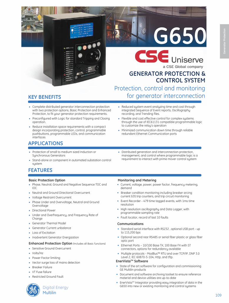
G650 Generator Protection and Control System.
52
3
1
3
1 50G 51G 67G
59G
50N 51N 67N
87RGF
59N
59X
27X
25
51V 55 VTFF 27/50
TRIP COIL SUPERVISION
493
50P 3
46 3
50-23
51-23
50BF1
40 3
32 3 6 3 1 3 3 3 3
3
59P3
24 47 3 3
27 3
78V 3 3
3
3
1
81O 3
81U 3
3 3 3
3
81R 3
G
Enhanced Option Features
R
1
1
50SG 51SG 3 3
DEVICENUMBER
24 Volt / Hertz X25 Synchrocheck X X27 Phase Undervoltage X X27X Auxiliary Undervoltage X X32DIR Directional Power X X40 Loss of excitation X X46 Generator Unbalance X X47 Negative Sequence OV X X49S Generator Thermal Model X X50/27 Inadvertent Generator Energization X X50_2/51_2 Negative Sequence IOC / TOC X X50BF Breaker Failure X X50G/51G, 50N/51N Ground & Neutral IOC / TOC X X50P Phase IOC X X50SG/51SG Sensitive Ground Fault X51P/V Voltage Restraint Overcurrent X X55 Power Factor limiting X X59P Phase Overvoltage X X59X Auxiliary Overvoltage X X59N Neutral Overvoltage X X59G Ground Overvoltage X X67N Neutral Directional OC X X67G Ground Directional OC X X78V Voltage Surge / Loss of mains X81U/81O Under / Over frequency X X81R Frequency Rate of Change X X87G Restricted Ground Fault XVTFF Fuse Failure X
FUNCTION
ANSI DEVICE NUMBERS AND FUNCTIONSG650 Basic
G650 Enhanced
Functional Block DiagramANSI Device Numbers & Functions
Device Number Function27P Phase Undervoltage27X Auxiliary Undervoltage32R Reverse Power32L Low Forward Power46 Stator Current Unbalance47 Phase Reversal
50BF Breaker Failure50P Phase Instantaneous Overcurrent50N Neutral Instantaneous Overcurrent50G Ground Instantaneous Overcurrent51P Phase Time Overcurrent51N Neutral Time Overcurrent51G Ground Time Overcurrent51V Voltage Restrained Time Overcurrent59P Phase Overvoltage59X Auxiliary Overvoltage59N Neutral Overvoltage67P Phase Directional Overcurrent67N Neutral Directional Overcurrent67G Ground Directional Overcurrent60V Voltage Unbalance81O Overfrequency81U UnderfrequencyVTFF VT Fuse Fail
G650 Generator Protection & Control System
Gen
erat
or P
rote
ctio
nLoss of Excitation
Use the G650 for the detection of the loss of excitation of synchronous generators, and to automatically remove the generator from service. Loss of excitation can be damaging to the machine, and/or detrimental to the operation of the system. It is recommended that loss-of-excitation protection be considered for all synchronous generators. Protective relays are applied as backup protection for excitation systems, which in most cases include minimum-excitation limiters to prevent under-excitation. An offset mho characteristic was chosen to provide selectivity between loss of excitation and other normal or abnormal conditions that may exist on the system. The element provides two-stage impedance based protection and responds to the positive sequence voltage and current.
Breaker Failure
The breaker failure function determines if a breaker that was signaled to trip has not cleared a fault within a definite time, so further tripping action may be performed. The G650 provides the required current source inputs, digital inputs and outputs, and elements to perform breaker failure functions for a three pole tripping scheme. The function can be initiated and blocked internally and/or externally via input contacts or communications.
Overcurrent Protection
Instantaneous and Time Overcurrent functions are available for phase, neutral, ground, sensitive ground, and negative sequence currents. A variety of time curves are provided including IEC, IEEE/ ANSI, IAC, I2t , definite time, rectifier curve, and FlexCurve user curves. The phase Time Overcurrent elements have a voltage-restrained feature that can be enabled to allow for easy coordination with other equipment.
Sensitive ground current
The Sensitive Ground IOC (50SG) and Sensitive Ground TOC (51SG) are available in enhanced option can be used as 95% ground stator protection in generators grounded to a resistor.
used in conjunction with an automated system, use the G650 to aid the restoration process with synchronism check feature, as an independent check of the automatic synchronizer.
VT Fuse Failure
The VT fuse failure scheme that is available in the enhanced option, will detect a fuse failure condition through monitoring of the positive and negative sequence voltage and current.
AutomationThe control functions of the G650 include a full-featured virtual PLC with an optional graphical HMI display. The combination of both tools allow the user to set the G650 for total breaker control, which include real-time monitoring of breakers and auxiliary disconnecting devices, with open and close commands supervised by programmable interlocking functions.
Programmable Logic
The programmable logic engine in the G650 allows for creating customized control schemes to automatically control the interconnections between the generator and the transmission system. The programmable logic interface meets the IEC 61131-3 Functional Block Diagram industry standard method of programming logical controllers and contains all of the Boolean logic operators required to carry out most distributed generation automation applications.
Generator Current Unbalance
The negative sequence components of unbalance currents cause second harmonic currents to flow in the rotor that can lead to undetected overheating and consequently sever machine damage. The G650 meets ANSI standards to minimize risk of heat damage caused by unbalance in the generator.The G650 can be set either with a definite time (up to thousands) or with a I22t=K curve model where K is a value between 1 to 100.
Generator Thermal Model
The Generator Thermal Model function protects the generator from overheating as well as overloading. This element includes an overvaluing of the effect of the negative sequence I2 component in order to protect the generator from the effects caused by slight system unbalanced currents, such as the ones produced by load unbalance.
Synchronism Check
The synchronism check element is typically used at locations where the two parts of the system are interconnected through at least one other point in the system, which are to be joined by the closure of a circuit breaker. The G650 provides the required voltage source inputs, digital inputs and outputs, and elements to monitor differences in voltage magnitudes, phase angles, and frequencies to perform synchronism check across a circuit breaker. The G650 can be use to carry out full independent control over the associated breaker. When
A Loss of Mains condition is detected by means of angle displacement between one Voltage cycle and the previous one.
G650 Generator Protection & Control SystemG
ener
ator
Pro
tect
ion
Scalable Hardware
The G650 is available with up to 64 programmable digital inputs, up to 16 analog inputs and up to 16 digital outputs. Using the additional CIO module that is available, the digital inputs, analog inputs and digital outputs available are increased to 128, 32, and 32 respectively. All digital inputs may be filtered with a separate debounce time to tailor individual requirements. More over, programmable threshold allows the use of different voltage levels (20 to 230 VDC) for each input.
Multiple Setting Groups
Three separate setting groups for protection functions may be stored in the G650. The G650 includes three units for each protection function, all of which can be active simultaneously in a single group, or be grouped in three different tables. An easy to use programmable mechanism is provided to instantly switch the active settings. This switching may be done internally and/or externally via contact inputs or communications or combinations of the above.
Monitoring and MeteringThe G650 includes high accuracy metering and recording for all AC signals. Voltage, current, and power metering are built into the relay as a standard feature. Diagnostics features such as oscillography, and event recording, combined with EnerVistaTM software tools, significantly reduce troubleshooting time and simplify report generation in the event of a system fault .
Basic Metering Functions
The G650 provides the following metering values.
• Current:Ia,Ib,Ic,In,Ig,Isg
• Phase-to-phaseandphase-to-groundvoltage values for bus and line: Van, Vbn, Vcn, Vab, Vbc, Vca, Vx, Vn, Vg
• Activepower(perphaseandtotal):Wa,Wb, Wc, W.
• Reactivepower(perphaseandtotal):VARa, VARb, VARc, VAR.
• SystemFrequencyandFrequencyDecay Rate
These signals are available for local display, and accessible remotely using communications.
Oscillography
Up to 20 simultaneous Oscillography records can be recorded to monitor up to 9 fixed analog variables (IA, IB, IC, IG, IS,VI, VII, VIII and VX) and any physical I/O point or internal digital operand (up to 16 configurable channels). The waveform traces and digital states provide a visual display of power system and relay operational data captured during specified triggered events. Sampling rates of up to 3600 Hz can be recorded and the capacity of each record will depend on the configuration of Oscillography function.
Event Recorder
Capture the last 479 events, with 1 ms resolution time, to provide SOE recorder functionality. Consolidate the event records from multiple devices using EnerVista software tools and use the IRIG-B time synchronization feature to synchronize all events across a system of relays for even more accurate analysis and troubleshooting. These records are stored in non-volatile memory. Therefore, there is no need for internal battery monitoring or maintenance.
Trip Circuit Monitoring
The G650 offers as an option two complete supervision circuits for monitoring breaker trip and closing coils circuits. These supervision inputs monitor both the battery voltage level and the continuity of the trip and closing circuits by applying current through those circuits and checking that it flows properly.
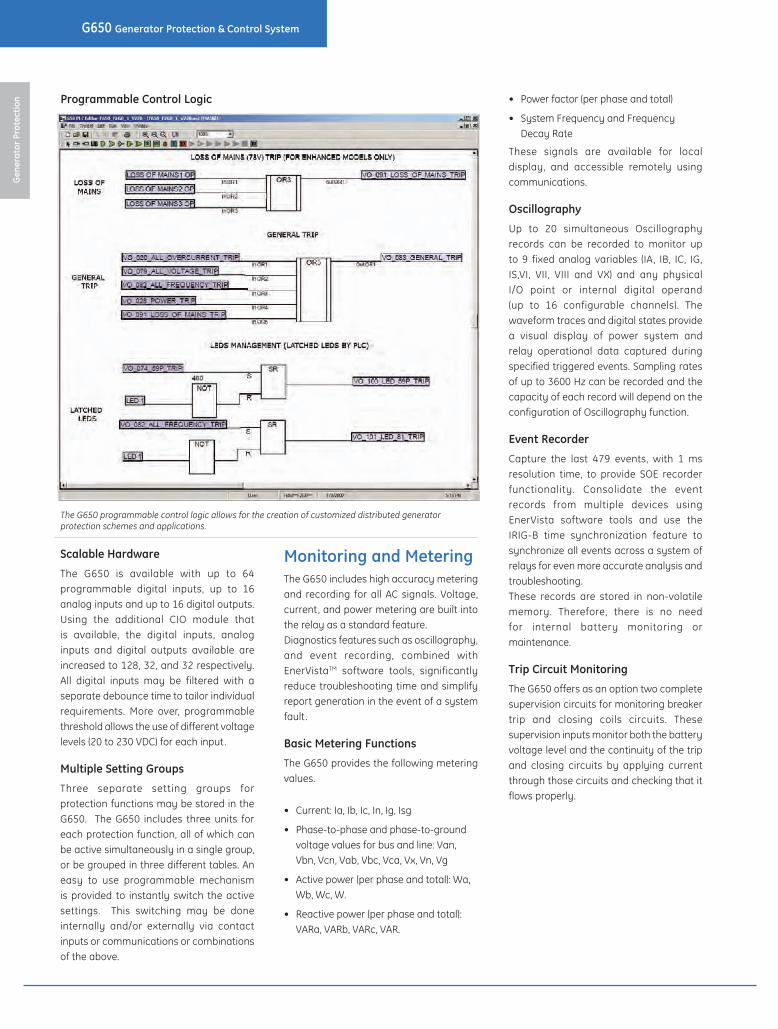
Programmable Control Logic
The G650 programmable control logic allows for the creation of customized distributed generator protection schemes and applications.
• Powerfactor(perphaseandtotal)
G650 Generator Protection & Control System
Gen
erat
or P
rote
ctio
nCommunicationsThe G650 supports a wide range of communication mediums and protocols compatible with new and existing communication infrastructures. The G650 includes a maximum of three independent communication ports: COM1, COM2 and COM3, with many physical choices through the use of two removable plug and play boards. COM1 and COM2 support Modbus® RTU, and serial DNP 3.0. They are located in the first plug and play board, with three different media choices: RS-485, and plastic or glass fiber optic. In addition, COM2 is accessible from the faceplate of the relay through opto-isolated RS232.COM3 supports ModBus TCP/IP and DNP 3.0 over Ethernet cable (10/100 Base TX) and fiber optic (100 Base FX). The Ethernet port is located in the second plug-and-play board with the options available shown in the table above.
User Interfaces
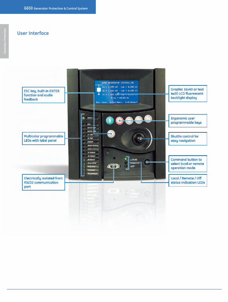
Keypad & Display
There are two displays available, one with text display (4x20 characters), and one optional large graphic display (16x40 characters) with fluorescent backlit for a better visibility under all conditions. Monitoring, metering and alarming panel screens can be produced just by clicking and dragging symbols from a complete library of symbols.
LED Indicators
Up to 15 programmable LEDs green, yellow and red, with tags tailored to the application. Five additional large keys, all of them configurable, help automating frequently performed control functions (such as breaker open, close, recloser lockout).
Shuttle
An easy to use "shuttle" type control plus an escape key makes the G650 extremely easy to use, similar to mouse navigation in a PC or a shuttle control in a domestic VCR.
Viewpoint Monitoring
Viewpoint Monitoring is a simple-to-use and full-featured monitoring and data recording software package for small systems. Viewpoint Monitoring provides a complete HMI package with the following functionality:
•Plug-&-PlayDeviceMonitoring
•SystemSingle-LineMonitoring&Control
•AnnunciatorAlarmScreens
•TrendingReports
•AutomaticEventRetrieval
•AutomaticWaveformRetrieval
EnerVista™ Integrator
EnerVistaTM Integrator is a toolkit that allows seamless integration of GE Multilin devices into new or existing automation systems. Included in EnerVista Integrator is:
•OPC/DDEServer
•GEMultilinDrivers
•AutomaticEventRetrieval
•AutomaticWaveformRetrieval
EnerVistaTM SoftwareThe EnerVista™ Suite is an industry-leading set of software programs that simplifies every aspect of using the G650 relay. The EnerVista suite provides all the tools to monitor the status of your the protected asset , maintain the relay, and integrate information measured by the G650 into DCS or SCADA monitoring systems. Convenient COMTRADE and Sequence of Events viewers are an integral part of the G650 Setup software included with every relay, to carry out postmortem event analysis to ensure proper protection system operation.
EnerVistaTM Launchpad
EnerVista™ Launchpad is a powerful software package that provides users with all of the setup and support tools needed for configuring and maintaining GE Multilin products. The setup software within Launchpad allows configuring devices in real-time by communicating using serial, Ethernet, or modem connections, or offline by creating setting files to be sent to devices at a later time.Included in Launchpad is a document archiving and management system that ensures critical documentation is up-to-date and available when needed. Documents made available include:
•Manuals
•ApplicationNotes
•GuideformSpecifications
•Brochures
•WiringDiagrams
•FAQs
•ServiceBulletins
G650 Generator Protection & Control SystemG
ener
ator
Pro
tect
ion
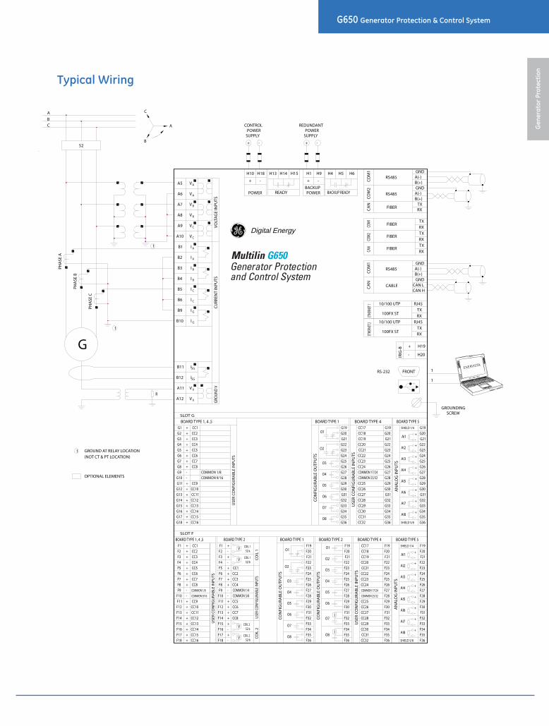
G650 Generator Controller System
User Interface
G650 Generator Protection & Control System
Gen
erat
or P
rote
ctio
n
Multilin G650Generator Protection and Control System
READY
VOLT
AGE
INPU
TS
V
VA5
A6
+
SUPPLYPOWER
CONTROL
-
H10
A
A
H13 H14H18
+ -
POWER
PHA
SE C
PHA
SE A
PHA
SE B
CURR
ENT
INPU
TS
C
V
V
V
V
A9
A7
A8
A10
B1 I
B2 I
B3 I
IB5
B4 I
B6 I
B
B
C
C
A
Digital Energy
A
B
B
C
V
V
A11
B9 I
B10 I
B12 I
B11 I
A12
GROU
ND V
X
G
G
SG
SG
X
SUPPLYPOWER
+
REDUNDANT
-
H9H1H15
POWER
+
BACKUP
-
H5 H6H4
BACKUP READY
USER
CON
FIGU
RABL
E INP
UTS
+F5 CC1
USE
R CO
NFI
GU
RABL
E IN
PUTS
+F5 CC5
COIL
2
VF18 CC16+ F18 -
F11
F17F16F15
F12
F14F13
F8
F10F9
F6F7
+F11 CC5CC9+
CC13CC14CC15+
++
F17F16F15
CC10
CC12CC11
+
++
F12
F14F13
+
+-
V
CC7CC6
CC8+
++
F8CC8+
--
F10F9
CC7CC6+
+F6F7
+ CC4
--
CC3CC2+
+
USE
R CO
NFI
GU
RABL
E IN
PUTS
CC11+G13
BOARD TYPE 1, 4 ,5
F2
F4F3
F1
G16
G18G17
G15G14
BOARD TYPE 2
F2CC2CC3CC4+
++
F4F3
CC1+ F1
COIL
1
+-
-V
+V
CC14+CC15CC16
++
CC12CC13
++
G10G11G12
G7G8G9
G4G5G6
G3G2G1
COMMON 9/16COMMON 1/8
CC9CC10
-++
CC7CC8
++-
CC4
CC6CC5
+
++
CC1
CC3CC2+
+
+
CC21 F23 F23
COMMON 17/24
COMMON 25/32
CC32
CC25
CC30CC31
CC29
CC27CC28
CC26
CC24CC23CC22
F36 F36
F29 F29
AI7
AI6
AI8F34F35
F33
F31F32
F30
+
+
-
- F35F34F33
-
+
-F30F31F32
AI3
AI4
AI5
F26
F28F27
F25F24
F26+
-
+ F28F27
+
-
- F25F24
BOARD TYPE 4
COMMON 17/24COMMON 25/32
G31
CON
FIG
URA
BLE
OU
TPU
TS
CC27
CC18
CC20CC19
CC17
G34
O8G36G35
O6
O7
G32G33
CC30CC31CC32
CC28CC29
O2
G28
O5 G29G30
O3
O4 G27G26G25
CC25CC26
CC23CC24
G24G23G22
O1G19
G21G20
CC20CC21CC22
CC17CC18CC19
G31 G31
SHIELD 1/4
AI1
BOARD TYPE 5
AI2
F20
F22F21
F19F20
-
+
+ F22F21
F19
SHIELD 5/8
AI8
AI7
G34
G36G35
G32G33
+ G34
- G35G36
-
+
-
G33G32
AI3
AI6
AI5
AI4
G28G29G30
G27G26G25
G28
+
-
+
G30G29
-
+
-
G25G26G27
SHIELD 1/4
AI2
AI1
G24G23G22
G19G20G21
+
-
+ G22G23G24
-
+ G20G21
G19BOARD TYPE 1, 4 ,5 BOARD TYPE 4BOARD TYPE 1 BOARD TYPE 5
CON
FIG
URA
BLE
OU
TPU
TS
F31
F34
O6
F35F36
O5
O4
F33F32
F28
O3
F30F29
O2
O1
F25F26F27
F22F23F24
F21F20F19
O7
O8I
I
BOARD TYPE 2
CON
FIG
URA
BLE
OU
TPU
TS
F31
F34
O8 F35F36
O7
O6
F33F32
F28
O5F30F29
O4
O3 F25F26F27
O2F22F23F24
O1 F20F21
F19BOARD TYPE 1
RXCOM1
COM
1 GND
RS485
RS485
COM
2CA
N
FIBER
FIBER
B(+)A(-)GNDB(+)A(-)
RXTX
TX
CAN
COM2 FIBER
FIBERRX
RXTX
TX
IRIG
-B
H20
H19+
-
100FX ST
ETHE
RNET
2
GND
CAN
RS485
COM
1 GND
B(+)A(-)
10/100 UTP
CABLE
100FX ST
10/100 UTP
ETHE
RNET
1
CAN LCAN H
RJ45
RJ45TX
RXTX
RX
SHIELD 5/8
1
1
1 GROUND AT RELAY LOCATION(NOT CT & PT LOCATION)
OPTIONAL ELEMENTS
COIL 152/a
52/bCOIL 1
52/bCOIL 2
COIL 252/a
COMMON 1/4COMMON 5/8
COMMON 1/8
COMMON 9/16
SLOT G
SLOT F
B
C
A
ABC
52
G
R
USE
R CO
NFI
GU
RABL
E IN
PUTS
AN
ALO
G IN
PUTS
USE
R CO
NFI
GU
RABL
E IN
PUTS
AN
ALO
G IN
PUTS
FRONTRS-232
GROUNDINGSCREW
1
1
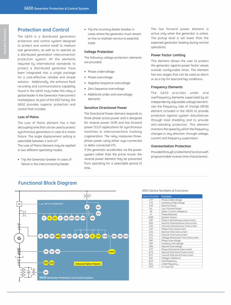
G650 Generator Controller System
Typical Wiring
G650 Generator Protection & Control SystemG
ener
ator
Pro
tect
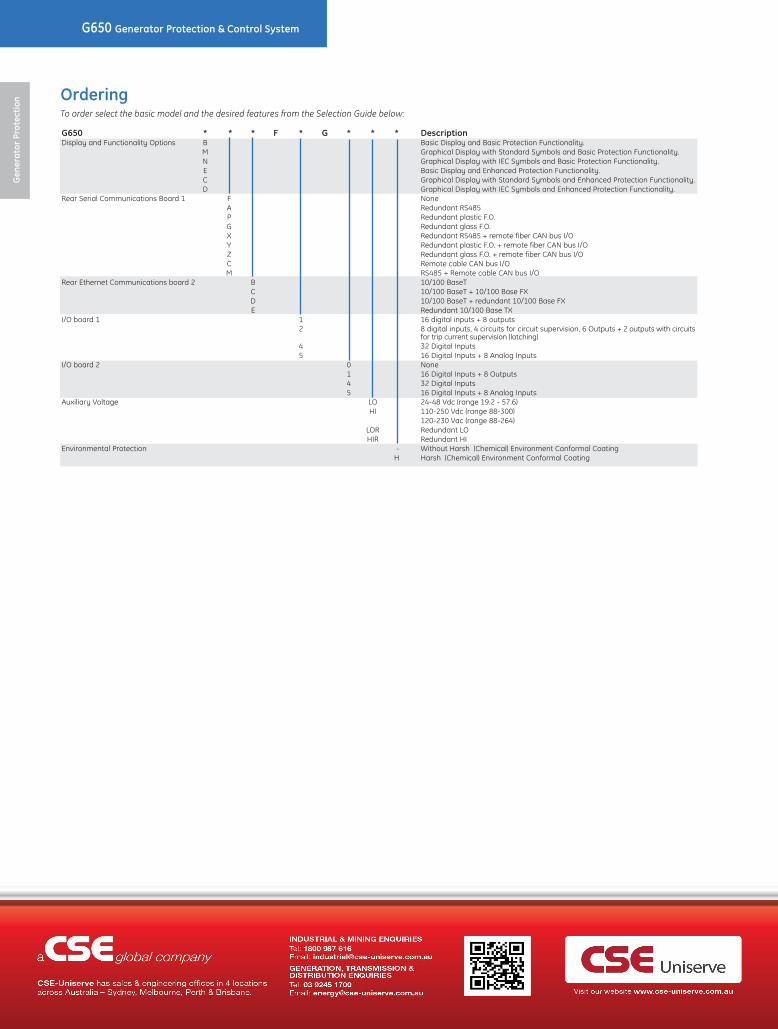
ion Ordering
To order select the basic model and the desired features from the Selection Guide below:
G650 * * * F * G * * * DescriptionDisplay and Functionality Options B Basic Display and Basic Protection Functionality. M Graphical Display with Standard Symbols and Basic Protection Functionality. N Graphical Display with IEC Symbols and Basic Protection Functionality. E Basic Display and Enhanced Protection Functionality. C Graphical Display with Standard Symbols and Enhanced Protection Functionality. D Graphical Display with IEC Symbols and Enhanced Protection Functionality. Rear Serial Communications Board 1 F None A Redundant RS485 P Redundant plastic F.O. G Redundant glass F.O. X Redundant RS485 + remote fiber CAN bus I/O Y Redundant plastic F.O. + remote fiber CAN bus I/O Z Redundant glass F.O. + remote fiber CAN bus I/O C Remote cable CAN bus I/O M RS485 + Remote cable CAN bus I/ORear Ethernet Communications board 2 B 10/100 BaseT C 10/100 BaseT + 10/100 Base FX D 10/100 BaseT + redundant 10/100 Base FX E Redundant 10/100 Base TXI/O board 1 1 16 digital inputs + 8 outputs 2 8 digital inputs, 4 circuits for circuit supervision, 6 Outputs + 2 outputs with circuits for trip current supervision (latching) 4 32 Digital Inputs 5 16 Digital Inputs + 8 Analog InputsI/O board 2 0 None 1 16 Digital Inputs + 8 Outputs 4 32 Digital Inputs 5 16 Digital Inputs + 8 Analog InputsAuxiliary Voltage LO 24-48 Vdc (range 19.2 - 57.6) HI 110-250 Vdc (range 88-300) 120-230 Vac (range 88-264) LOR Redundant LO HIR Redundant HIEnvironmental Protection - Without Harsh (Chemical) Environment Conformal Coating H Harsh (Chemical) Environment Conformal Coating