Embed Size (px)
Citation preview
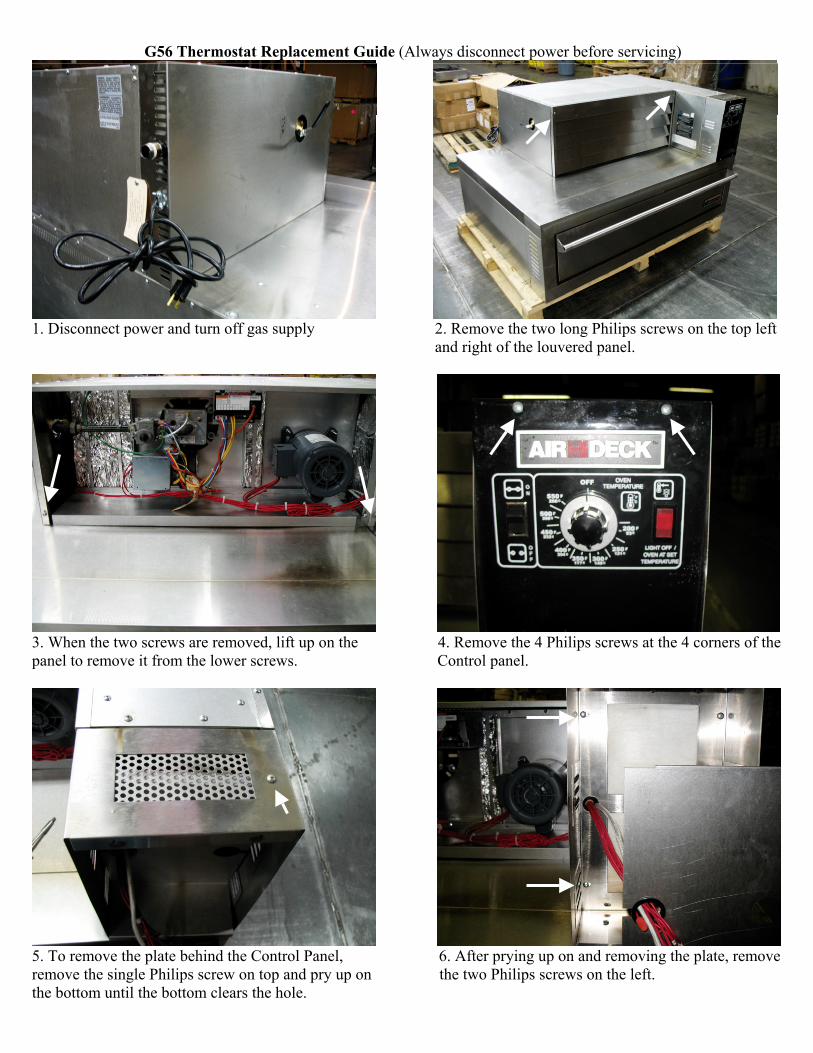
G56 Thermostat Replacement Guide (Always disconnect power before servicing)
1. Disconnect power and turn off gas supply 2. Remove the two long Philips screws on the top left and right of the louvered panel.
3. When the two screws are removed, lift up on the 4. Remove the 4 Philips screws at the 4 corners of the panel to remove it from the lower screws. Control panel.
5. To remove the plate behind the Control Panel, 6. After prying up on and removing the plate, remove remove the single Philips screw on top and pry up on the two Philips screws on the left. the bottom until the bottom clears the hole.
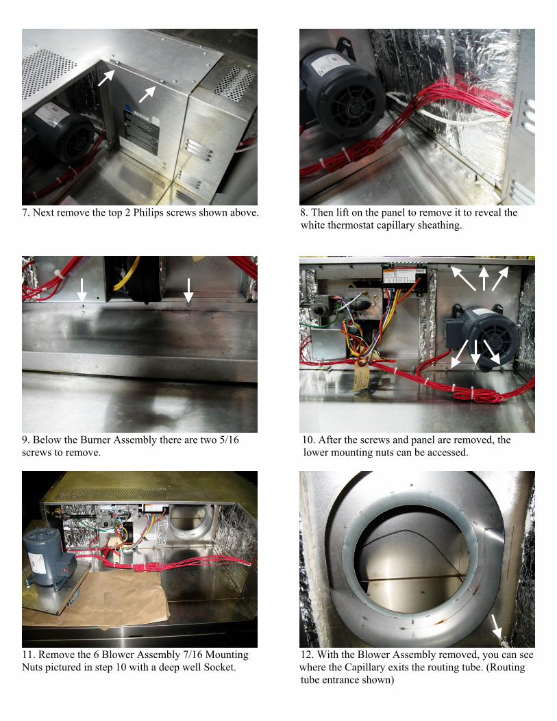
7. Next remove the top 2 Philips screws shown above. 8. Then lift on the panel to remove it to reveal the
white thermostat capillary sheathing.
9. Below the Burner Assembly there are two 5/16 10. After the screws and panel are removed, the screws to remove. lower mounting nuts can be accessed.
11. Remove the 6 Blower Assembly 7/16 Mounting 12. With the Blower Assembly removed, you can see Nuts pictured in step 10 with a deep well Socket. where the Capillary exits the routing tube. (Routing tube entrance shown)
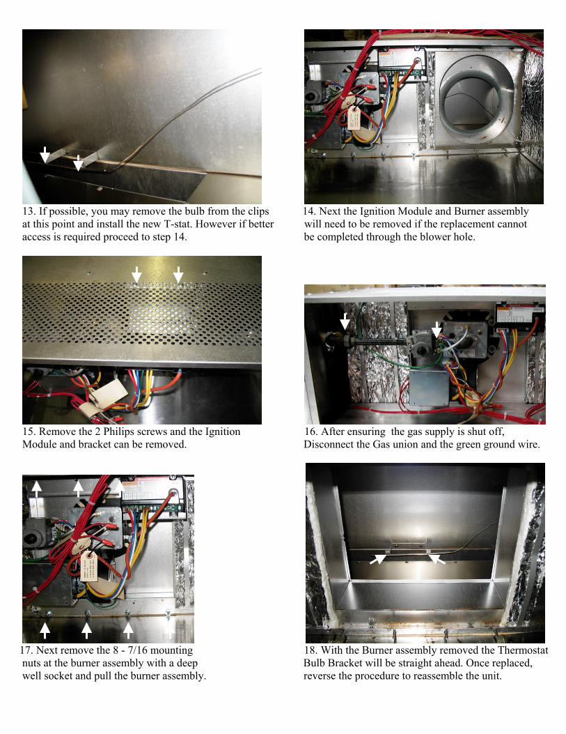
13. If possible, you may remove the bulb from the clips 14. Next the Ignition Module and Burner assembly at this point and install the new T-stat. However if better will need to be removed if the replacement cannot access is required proceed to step 14. be completed through the blower hole.
15. Remove the 2 Philips screws and the Ignition 16. After ensuring the gas supply is shut off, Module and bracket can be removed. Disconnect the Gas union and the green ground wire.
17. Next remove the 8 - 7/16 mounting 18. With the Burner assembly removed the Thermostat nuts at the burner assembly with a deep Bulb Bracket will be straight ahead. Once replaced, well socket and pull the burner assembly. reverse the procedure to reassemble the unit.