Embed Size (px)
Citation preview

Where Hardware Meets Software
GHI Electronics, LLC 501 E. Whitcomb Ave.
Madison Heights, Michigan 48071 Phone: (248) 397-8856
Fax: (248) 397-8890 www.ghielectronics.com
G400S and G400D SoM Datasheet
G400S SoM G400D SoM

GHI Electronics, LLC Introduction G400S and G400D SoM Datasheet
Rev 1.1 2 www.ghielectronics.com
1 Contents
2 Introduction .......................................................................................................................................................... 4 2.1 G400S vs G400D ........................................................................................................................................... 4 2.2 Key Features ................................................................................................................................................. 5 2.3 Example Applications ................................................................................................................................... 5
3 The .NET Micro Framework .................................................................................................................................. 6 3.1 GHI Electronics and NETMF .......................................................................................................................... 6
4 Pinout Tables ........................................................................................................................................................ 7 4.1 G400S Pinout ................................................................................................................................................ 7 4.2 G400D Pinout ............................................................................................................................................... 8
5 Reference Design .................................................................................................................................................. 9 6 Device Startup ..................................................................................................................................................... 10 7 Libraries .............................................................................................................................................................. 11
7.1 General Purpose Input and Output (GPIO) ................................................................................................ 11 7.2 Analog Input ............................................................................................................................................... 11 7.3 Pulse Width Modulation (PWM) ................................................................................................................ 11 7.4 Signal Generator ........................................................................................................................................ 11 7.5 Signal Capture ............................................................................................................................................ 11 7.6 Pulse Feedback ........................................................................................................................................... 11 7.7 Universal Asynchronous Receiver Transmitter (UART) .............................................................................. 12 7.8 Serial Peripheral Interface (SPI) ................................................................................................................. 12 7.9 Inter-Integrated Circuit (I2C) ...................................................................................................................... 12 7.10 Controller Area Network (CAN) .................................................................................................................. 12 7.11 1-Wire ........................................................................................................................................................ 12 7.12 Graphics ..................................................................................................................................................... 12 7.13 Touch Screen .............................................................................................................................................. 13 7.14 USB Host ..................................................................................................................................................... 13 7.15 USB Client ................................................................................................................................................... 13 7.16 File System ................................................................................................................................................. 13 7.17 Networking ................................................................................................................................................. 13
7.17.1 Ethernet ............................................................................................................................................. 13 7.17.2 Wi-Fi .................................................................................................................................................. 13 7.17.3 Point to Point ..................................................................................................................................... 13
7.18 Extended Weak References ....................................................................................................................... 14 7.19 Configuration ............................................................................................................................................. 14 7.20 Real Time Clock .......................................................................................................................................... 14 7.21 Watchdog ................................................................................................................................................... 14 7.22 Power Control ............................................................................................................................................ 14 7.23 In-Field Update ........................................................................................................................................... 14 7.24 SQLite Database ......................................................................................................................................... 14 7.25 Direct Memory Access ............................................................................................................................... 14 7.26 Battery RAM ............................................................................................................................................... 15 7.27 Runtime Loadable Procedures ................................................................................................................... 15
8 Design Considerations ........................................................................................................................................ 16 8.1 Required Pins ............................................................................................................................................. 16 8.2 Power Supply ............................................................................................................................................. 16 8.3 Crystals ....................................................................................................................................................... 16 8.4 SPI Channels ............................................................................................................................................... 16 8.5 Ethernet ..................................................................................................................................................... 16 8.6 Direct Memory Access ............................................................................................................................... 16
9 Footprints ............................................................................................................................................................ 17 9.1 G400S Recommended Footprint ................................................................................................................ 17

GHI Electronics, LLC Introduction G400S and G400D SoM Datasheet
Rev 1.1 3 www.ghielectronics.com
9.2 G400D Recommended Footprint ............................................................................................................... 17 10 Soldering the G400S ............................................................................................................................................ 18
10.1 Oven Reflow ............................................................................................................................................... 18 11 Legal Notice ........................................................................................................................................................ 19
11.1 Licensing ..................................................................................................................................................... 19 11.2 Trademarks ................................................................................................................................................ 19 11.3 Disclaimer ................................................................................................................................................... 19
12 Revision History .................................................................................................................................................. 20

GHI Electronics, LLC Introduction G400S and G400D SoM Datasheet
Rev 1.1 4 www.ghielectronics.com
2 Introduction
The G400 SoMs are powerful, low-cost, surface-mount System on Modules (SoM) running Microsoft's .NET Micro
Framework. The .NET Micro Framework enables the SoM to be programmed from Microsoft Visual Studio using a
USB or serial cable. Programming in a modern managed language, such as C# or Visual Basic, allows developers to
accomplish more work in less time by taking advantage of the extensive built-in libraries for networking, file
systems, graphical interfaces, and more.
A simple two-layer circuit board with a power source and a few connectors can utilize the G400 SoMs to bring the
latest technologies to any product. There are no additional licensing or other fees and all the development tools
are provided freely.
Throughout this document, the G400S SoM and the G400D SoM will be referred to as the G400S and G400D,
respectively. When only G400 is listed, the information applies to both the G400S and the G400D unless specified
otherwise.
For more information and support, please see https://www.ghielectronics.com/support/netmf and the product
catalog entry. For advanced electrical characteristics and details on the underlying SAM9X35 processor, please
consult the processor’s datasheet.
2.1 G400S vs G400D
The G400 comes in a standard and an extended format. They are not pinout compatible. The below table lists the
differences.
G400S G400D
Package 120 pin surface-mount module (SMT) 200 pin SODIMM module
Dimensions 48.3 x 33.1 x 4.6 mm 67.6 x 31.8 x 4.1 mm
GPIO 89 102
Analog Input 12 8
Ethernet ENC28J60 over SPI ENC28J60 over SPI and/or Built in base 100 Ethernet PHY

GHI Electronics, LLC Introduction G400S and G400D SoM Datasheet
Rev 1.1 5 www.ghielectronics.com
2.2 Key Features
.NET Micro Framework
RoHS Lead Free
400 MHz ARM 9 Atmel SAM9X35
64 Mbytes available RAM
1.4 Mbytes available flash
Embedded LCD controller
89 to 102 interrupt capable GPIO
2 SPI
1 I2C
6 UART
2 CAN
4 PWM
8 to 12 10-bit analog input
4-bit SD/MMC memory card interface
Low power modes
-40°C to +85°C operational
RTC
Watchdog
Threading
USB host
USB client
SQLite database
TCP/IP with SSL
o Full .NET socket interface
o Ethernet
o Wi-Fi
o PPP
Graphics
o Images
o Fonts
o Controls
File System
o Full .NET file interface
o SD cards
o USB drives
Native extensions
o Runtime Loadable Procedures
o Device register access
Signal controls
o Generation
o Capture
o Pulse measurement
2.3 Example Applications
Vending machines
POS Terminals
Measurement tools and testers
Networked sensors
Robotics
Central alarm system
Smart appliances
Industrial automation devices

GHI Electronics, LLC The .NET Micro Framework G400S and G400D SoM Datasheet
Rev 1.1 6 www.ghielectronics.com
3 The .NET Micro Framework
Inspired by the full .NET Framework, Microsoft developed a lightweight version called .NET Micro Framework
(NETMF). NETMF focuses on the specific requirements of resource-constrained embedded systems. Development,
debugging, and deployment are all conveniently performed using Microsoft's powerful Visual Studio through a
standard USB or serial cable.
Programming is done in C# or Visual Basic with libraries that cover sockets, memory management with garbage
collection, advanced file system support, multitasking services, and many others. In addition to supporting many
standard .NET features, NETMF has additional embedded extensions supporting microcontroller specific needs
such as PWM outputs and analog inputs.
3.1 GHI Electronics and NETMF
Since signing the partnership agreement with Microsoft in 2008, GHI Electronics has become the leading Microsoft
partner on NETMF through its work on integrating and extending the NETMF core. GHI Electronics's NETMF
products are extended with important features extending the NETMF libraries such as databases, USB Host, Wi-Fi,
and native programming.

GHI Electronics, LLC Pinout Tables G400S and G400D SoM Datasheet
Rev 1.1 7 www.ghielectronics.com
4 Pinout Tables
Many signals on the G400 are multiplexed to offer multiple functions on a single pin. Developers can decide on the
pin functionality to be used through the provided libraries. Any pin with no name, function, or note must be left
unconnected.
4.1 G400S Pinout
Pin Name Function Pin Name Function Pin Name Function
1 PD0 41 PB10 ADC11 81 PA23 SPI2 SCK
2 PD4 42 3.3 V 82 PA28
3 43 VBAT 831 PA31 I2C SCL
4 PA27 44 PB7 ADC8 84 3.3 V
5 PA16 SD CMD 45 PB2 85
6 PA8 COM4 RX 46 PC0 LCD B0 86 USBC D+
7 PA3 COM2 CTS 47 PC6 LCD G1 87 USBC D-
8 PA2 COM2 RTS 48 1.8 V 88 USBH0 D+
9 PC28 LCD HS 49 PC10 LCD G5 89 USBH0 D-
10 PC23 50 PC3 LCD B3 90 USBH1 D+
11 PC5 LCD G0 51 PC15 LCD R4 91 USBH1 D-
12 PC1 LCD B1 52 PC18 PWM0 92
13 1.8 V 53 1.0 V 93 RESET
14 54 PC13 LCD R2 94
15 55 PC31 95
16 GND 56 GND 96
17 PB3 57 PC26 97 GND
18 PB1 58 PC30 LCD CLK 98 SPI1 SCK
19 59 SPI1 MOSI 99 PA19 SD D2
20 PB18 60 PB16 ADC5 100 PA21 SPI2 MISO
21 PB8 ADC9 61 PB17 ADC6 101 PA24 LDR0
22 PB14 ADC3 62 PB9 ADC10 102 PA25 MODE
23 PB12 ADC1 TOUCH YU 63 PB4 103 1.0 V
24 PB6 ADC7 64 PC4 LCD B4 104
25 PB15 ADC4 65 PC7 LCD G2 105
26 PB0 66 PC8 LCD G3 COM5 TX 106 PA6 COM3 RX CAN2 RD
27 PB5 67 PC14 LCD R3 107 PA17 SD CLK
28 PC2 LCD B2 68 PC16 COM6 TX 108 PA22 SPI2 MOSI
29 PC9 LCD G4 COM5 RX 69 PC20 PWM2 109 PA26
30 PC11 LCD R0 70 PC17 COM6 RX 1101 PA30 I2C SDA
31 PC12 LCD R1 71 PC27 LCD VS 111 PA29
32 PC24 72 PC29 LCD OE 112
33 PA0 COM2 TX 73 PA5 COM3 TX CAN2 TD 113
34 PC21 PWM3 74 PA1 COM2 RX 114 PD2 TOUCH XR
35 PC19 PWM1 75 SPI1 MISO 115 PD1 TOUCH YD
36 PC22 76 PA10 COM1 TX CAN1 TD 116 PD7
37 PA7 COM4 TX 77 PA9 COM1 RX CAN1 RD 117 PD3
38 PA4 LDR1 78 PA15 SD D0 118 PD5
39 PB11 ADC0 79 PA18 SD D1 119 PD6
40 PB13 ADC2 TOUCH XL 80 PA20 SD D3 120 GND
1Open drain requiring a 2.2 kΩ pull-up resistor
GHI Electronics, LLC Pinout Tables G400S and G400D SoM Datasheet
Rev 1.1 8 www.ghielectronics.com
4.2 G400D Pinout
Pin Name Function Pin Name Function Pin Name Function Pin Name Function
1 GND 51 GND 101 PC31 151 GND
2 ETH PHY TX- 52 102 PA0 COM2 TX 152 PC0 LCD B0
3 53 103 PA1 COM2 RX 153 PC1 LCD B1
4 ETH PHY TX+ 54 104 PB12 ADC1 TOUCH YU 154 PC2 LCD B2
5 GND 55 105 PC18 PWM0 155 PC3 LCD B3
6 ETH PHY RX- 56 106 3.3 V 156 PC4 LCD B4
7 57 PD18 107 SPI1 MISO 157 PB13 ADC2 TOUCH XL
8 ETH PHY RX+ 58 PD17 108 SPI1 MOSI 158 PB14 ADC3
9 59 PD16 109 SPI1 SCK 159 PB15 ADC4
10 ETH PHY SPEED 60 3.3 V 110 PB17 ADC6 160 3.3 V
11 ETH PHY LINK 61 PD15 111 PA4 LDR1 161 PC5 LCD G0
12 62 PD14 112 PC19 PWM1 162 PC6 LCD G1
13 GND 63 PD13 113 GND 163 PC7 LCD G2
14 64 PD12 114 PB16 ADC5 164 PC8 LCD G3 COM5 TX
15 65 GND 1151 PA30 I2C SDA 165 PC9 LCD G4 COM5 RX
16 66 PD11 1161 PA31 I2C SCL 166 PD1 TOUCH YD
17 67 PD10 117 PA9 COM1 RX CAN1 RD 167 PA8 COM4 RX
18 68 PD9 118 PA10 COM1 TX CAN1 TD 168 PC15 LCD R4
19 69 PD8 119 PC24 169 GND
20 3.3 V 70 120 PA2 COM2 RTS 170 PC10 LCD G5
21 71 121 PA3 COM2 CTS 171 PC11 LCD R0
22 72 3.3 V 122 PD7 172 PC12 LCD R1
23 73 123 PA15 SD D0 173 PC13 LCD R2
24 74 124 3.3 V 174 PC14 LCD R3
25 75 125 PA16 SD CMD 175 PA23 SPI2 CLK
26 76 126 PA17 SD CLK 176 PA21 SPI2 MISO
27 GND 77 127 PA18 SD D1 177
28 78 128 PA19 SD D2 178 PA22 SPI2 MOSI
29 79 GND 129 PA20 SD D3 179
30 80 130 PC21 PWM3 180 3.3 V
31 81 131 GND 181
32 3.3 V 82 132 PC26 182 USBH1 D+
33 83 133 PC20 PWM2 183 VBAT
34 84 134 PA24 LDR0 184 USBH1 D-
35 85 135 PA25 MODE 185 GND
36 86 136 PA26 186 GND
37 87 137 PA27 187 RESET
38 88 3.3 V 138 PA28 188 USBH0 D+
39 89 139 PA29 189
40 GND 90 140 PC16 COM6 TX 190 USBH0 D-
41 GND 91 PB8 ADC9 141 PC17 COM6 RX 191
42 92 PD2 TOUCH XR 142 3.3 V 192 3.3 V
43 93 PC23 143 PC27 LCD VS 193
44 94 PD0 144 PC28 LCD HS 194 USBC D+
45 95 GND 145 PC30 LCD CLK 195
46 3.3 V 96 PB18 146 PC29 LCD OE 196 USBC D-
47 97 PB11 ADC0 147 PD3 197
48 98 PA5 COM3 TX CAN2 TD 148 PD4 198 GND
49 99 PA6 COM3 RX CAN2 RD 149 PD5 199
50 100 PC22 150 PD6 200 PA7 COM4 TX
1Open drain requiring a 2.2 kΩ pull-up resistor

GHI Electronics, LLC Reference Design G400S and G400D SoM Datasheet
Rev 1.1 9 www.ghielectronics.com
5 Reference Design
The G400D Dev Board is an excellent starting point and reference design for anyone interested in evaluating and
developing with the G400. See the product catalog entry for more information and additional resources.

GHI Electronics, LLC Device Startup G400S and G400D SoM Datasheet
Rev 1.1 10 www.ghielectronics.com
6 Device Startup
The G400 is held in reset when the reset pin is low. Releasing it will begin the system startup process. It is pulled
high internally.
There are four different components of the device firmware:
1. GHI Bootloader: initializes the system, updates TinyBooter when needed, and executes TinyBooter.
2. TinyBooter: executes TinyCLR, updates TinyCLR when needed, and updates the system configuration.
3. TinyCLR: loads, debugs, and executes the managed application.
4. Managed application: the program developed by the customer.
Which components get executed on startup can be control by manipulating the LDR0 and LDR1 pins. LDR0 and
LDR1 are pulled high on startup.
LDR0 LDR1 Effect
Ignored High Execute the managed application.
High Low Wait in TinyBooter
Low Low Wait in GHI Bootloader
Additionally, the communications interface between the host PC and the G400 is selected on startup through the
MODE pin, which is pulled high on startup. The USB interface is selected when MODE is high and COM1 is selected
when MODE is low.
The above discussed functions of LDR0, LDR1, and MODE are only during startup. After startup, they return to the
default GPIO state and are available to use as GPIO in the user application.
GHI Electronics, LLC Libraries G400S and G400D SoM Datasheet
Rev 1.1 11 www.ghielectronics.com
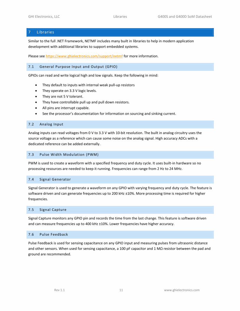
7 Libraries
Similar to the full .NET Framework, NETMF includes many built in libraries to help in modern application
development with additional libraries to support embedded systems.
Please see https://www.ghielectronics.com/support/netmf for more information.
7.1 General Purpose Input and Output (GPIO)
GPIOs can read and write logical high and low signals. Keep the following in mind:
They default to inputs with internal weak pull-up resistors
They operate on 3.3 V logic levels.
They are not 5 V tolerant.
They have controllable pull up and pull down resistors.
All pins are interrupt capable.
See the processor’s documentation for information on sourcing and sinking current.
7.2 Analog Input
Analog inputs can read voltages from 0 V to 3.3 V with 10-bit resolution. The built in analog circuitry uses the
source voltage as a reference which can cause some noise on the analog signal. High accuracy ADCs with a
dedicated reference can be added externally.
7.3 Pulse Width Modulation (PWM)
PWM is used to create a waveform with a specified frequency and duty cycle. It uses built-in hardware so no
processing resources are needed to keep it running. Frequencies can range from 2 Hz to 24 MHz.
7.4 Signal Generator
Signal Generator is used to generate a waveform on any GPIO with varying frequency and duty cycle. The feature is
software driven and can generate frequencies up to 200 kHz ±10%. More processing time is required for higher
frequencies.
7.5 Signal Capture
Signal Capture monitors any GPIO pin and records the time from the last change. This feature is software driven
and can measure frequencies up to 400 kHz ±10%. Lower frequencies have higher accuracy.
7.6 Pulse Feedback
Pulse Feedback is used for sensing capacitance on any GPIO input and measuring pulses from ultrasonic distance
and other sensors. When used for sensing capacitance, a 100 pF capacitor and 1 MΩ resistor between the pad and
ground are recommended.
GHI Electronics, LLC Libraries G400S and G400D SoM Datasheet
Rev 1.1 12 www.ghielectronics.com
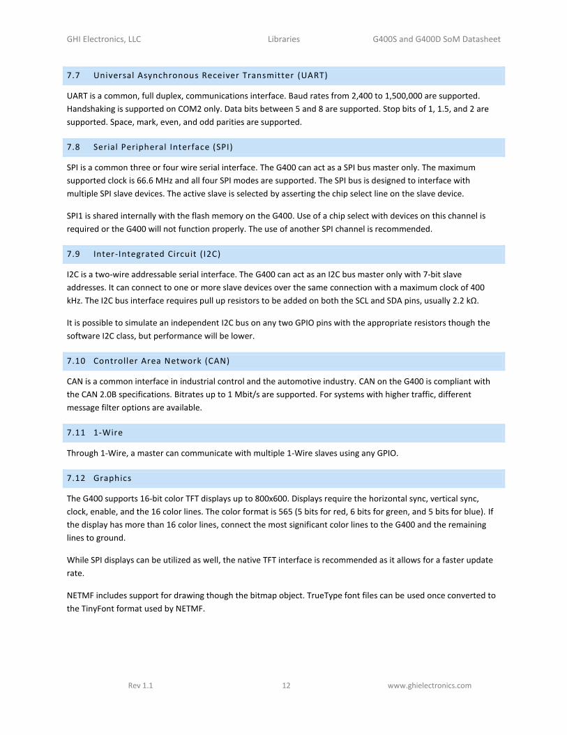
7.7 Universal Asynchronous Receiver Transmitter (UART)
UART is a common, full duplex, communications interface. Baud rates from 2,400 to 1,500,000 are supported.
Handshaking is supported on COM2 only. Data bits between 5 and 8 are supported. Stop bits of 1, 1.5, and 2 are
supported. Space, mark, even, and odd parities are supported.
7.8 Serial Peripheral Interface (SPI)
SPI is a common three or four wire serial interface. The G400 can act as a SPI bus master only. The maximum
supported clock is 66.6 MHz and all four SPI modes are supported. The SPI bus is designed to interface with
multiple SPI slave devices. The active slave is selected by asserting the chip select line on the slave device.
SPI1 is shared internally with the flash memory on the G400. Use of a chip select with devices on this channel is
required or the G400 will not function properly. The use of another SPI channel is recommended.
7.9 Inter-Integrated Circuit ( I2C)
I2C is a two-wire addressable serial interface. The G400 can act as an I2C bus master only with 7-bit slave
addresses. It can connect to one or more slave devices over the same connection with a maximum clock of 400
kHz. The I2C bus interface requires pull up resistors to be added on both the SCL and SDA pins, usually 2.2 kΩ.
It is possible to simulate an independent I2C bus on any two GPIO pins with the appropriate resistors though the
software I2C class, but performance will be lower.
7.10 Controller Area Network (CAN)
CAN is a common interface in industrial control and the automotive industry. CAN on the G400 is compliant with
the CAN 2.0B specifications. Bitrates up to 1 Mbit/s are supported. For systems with higher traffic, different
message filter options are available.
7.11 1-Wire
Through 1-Wire, a master can communicate with multiple 1-Wire slaves using any GPIO.
7.12 Graphics
The G400 supports 16-bit color TFT displays up to 800x600. Displays require the horizontal sync, vertical sync,
clock, enable, and the 16 color lines. The color format is 565 (5 bits for red, 6 bits for green, and 5 bits for blue). If
the display has more than 16 color lines, connect the most significant color lines to the G400 and the remaining
lines to ground.
While SPI displays can be utilized as well, the native TFT interface is recommended as it allows for a faster update
rate.
NETMF includes support for drawing though the bitmap object. TrueType font files can be used once converted to
the TinyFont format used by NETMF.

GHI Electronics, LLC Libraries G400S and G400D SoM Datasheet
Rev 1.1 13 www.ghielectronics.com
7.13 Touch Screen
The G400 supports displays with four-wire restive touch without the need for any additional hardware, though
using an external controller is possible. The default touch pins can be remapped if required. Capacitive touch
displays can be used through the I2C interface.
7.14 USB Host
USB host allows the use of USB mass storage devices, joysticks, keyboards, and mice. Additionally, for USB devices
that do not have a standard class included, low level USB access is provided for bulk transfers. USB hubs are
supported allowing multiple devices to be connected.
7.15 USB Client
The USB client interface is typically used as the G400 debug interface and for application deployment through
Visual Studio. However, it is controllable and may be used to simulate other USB devices such as mice, keyboards,
and Communications Device Class (CDC) interfaces using low level access instead of the debug interface.
7.16 File System
The G400 supports accessing files on SD cards and USB memory devices formatted as FAT16 or FAT32. SD cards
use a true 4-bit interface. SD/SDHC/SDXC cards in full, mini, and micro formats and any USB device with mass
storage class are supported. Access speeds are dependent on many different factors and can be up to 500 Kbyte/s.
7.17 Networking
The G400 supports Ethernet, Wi-Fi, and PPP through the built in LwIP stack. The full stack includes TCP, UDP,
DHCP, DNS, HTTP, FTP, and others. Secure connections can be created using the built in SSL stack.
7.17.1 Ethernet
Ethernet support is available using the built-in NETMF TCP/IP and SSL stack through the on-board base-100
Ethernet PHY on the G400D and through an external ENC28J60 SPI Ethernet chip on both the G400S and the
G400D.
7.17.2 Wi-Fi
Any Wi-Fi module with a built-in TCP/IP stack can be used with the G400. However, these modules are typically
limited. Through the supported Redpine RS9110-N-11-22-04 and RS9110-N-11-22-05 chips, Wi-Fi is usable with the
built-in NETMF TCP/IP and SSL stacks.
7.17.3 Point to Point
The Point to Point (PPP) protocol is often used for devices needing to connect to mobile networks. While typical
embedded devices use the mobile modem's built-in and very limited TCP/IP stack, systems using the G400 can use
these modems with the internal NETMF TCP/IP and SSL stack.

GHI Electronics, LLC Libraries G400S and G400D SoM Datasheet
Rev 1.1 14 www.ghielectronics.com
7.18 Extended Weak References
Extended Weak References are a way for managed applications to store data in non-volatile memory. This is meant
to be used as a configuration store that does not change frequently where the data can be recreated if needed.
There are 128 KBytes available for use.
7.19 Configuration
Access to the configuration sector of the device is provided for storage of small, infrequently changing, entries. The
data will be lost if the configuration is reflashed. Space is limited and varies based on other information stored in
the configuration.
7.20 Real Time Clock
The real time clock (RTC) is used to keep time while the processor is off, drawing its power from a backup battery
or super capacitor providing 1.65 V to 3.6 V. The required circuitry and crystal are included.
7.21 Watchdog
Watchdog is used to reset the system if it enters an erroneous state. The G400 supports timeouts between 1 ms
and 15,995 ms. Watchdog support is included through the GHI Electronics libraries replacing the built in NETMF
version.
7.22 Power Control
The G400 supports entering sleep, deep sleep, and off modes in order to reduce power usage. It can consume as
little as 56 mA in sleep, 27 mA in deep sleep, and 20 mA in off. It may be woken from an RTC alarm or a GPIO
interrupt. Sleep pauses execution of the program. Deep sleep pauses execution of the program and shuts down
many internal functions. Off shuts down all internal functions and can only be woken by the RTC alarm or a system
reset. The system will be automatically reset when exiting off mode.
7.23 In-Field Update
Through In-Field Update, the G400 can update its firmware and managed application. The update can come from
the network, a bus, or connected media.
7.24 SQLite Database
SQLite can be used to created databases that can be stored in memory or on a supported storage device such as a
USB drive or SD card.
7.25 Direct Memory Access
Low level device registers and memory can be accessed to further configure the G400’s underlying processor. Not
all functionality of the processor is available as some functions may be used or configured internally for use in
NETMF.

GHI Electronics, LLC Libraries G400S and G400D SoM Datasheet
Rev 1.1 15 www.ghielectronics.com
7.26 Battery RAM
Battery-backed RAM is provided as part of the internal RTC. This memory retains its contents when the power is
lost as long as there is a backup battery. There are 16 bytes of battery backed RAM available. Consult the
processor's documentation for details on use.
7.27 Runtime Loadable Procedure s
Similar to code loaded from a DLL, Runtime Loadable Procedures (RLP) allows a binary or ELF image to be loaded
into memory and executed on the device. This is useful for advanced and critical performance scenarios. The RLP
region starts at address 0xA0000000 and is 0x16FFFFC bytes in size. Your compiled images must fall completely
within that range.

GHI Electronics, LLC Design Considerations G400S and G400D SoM Datasheet
Rev 1.1 16 www.ghielectronics.com
8 Design Considerations
8.1 Required Pins
Exposing the following pins is required in every design to enable device programming, updates, and recovery:
LDR0
LDR1
Desired debug interface(s)
MODE if required to select a debug interface
SPI1 MISO to update TinyBooter in SDK 2015 R1 and earlier and to install the GHI Bootloader once for SDK
2016 R1 and later
8.2 Power Supply
A typical clean power source, suited for digital circuitry, is needed to power the G400. Voltages should be within at
least 10% of the needed voltage. Decoupling capacitors of 0.1 μF are needed near every power pin. Additionally, a
large capacitor, typically 47 μF, should be near the G400 if the power supply is more than few inches away.
Additionally, the G400 requires additional voltages beyond the typical 3.3 V to function properly. See the pinout
table for details.
8.3 Crystals
The G400 includes the needed system and RTC crystals and their associated circuitry.
8.4 SPI Channels
SPI1 is shared internally with the flash memory on the G400. Use of a chip select with devices on this channel is
required or the G400 will not function properly. The use of another SPI channel is recommended.
8.5 Ethernet
The built in Ethernet available on the G400D includes all needed Ethernet circuitry internally. However, an
appropriate magnet and connector, like the J0011D or similar, are required.
8.6 Direct Memory Access
Most of the core processor’s resources are used by NETMF. Some resources are permanently used, like the main
system timer while others are used when specific features, like the timers for PWM, are enabled. Used resources
can change from one firmware version to another so care must be taken when using these resources through RLP
or other direct memory access methods.
When absolutely required, applications can use resources in conjunction with NETMF. For example, creating a
special baud rate, utilizing the timer capture feature, and making use of many other features supported by the
processor. Please contact GHI Electronics’s consulting services to determine exactly what resources are available
and if the G400 can fulfill the specific requirements.

GHI Electronics, LLC Footprints G400S and G400D SoM Datasheet
Rev 1.1 17 www.ghielectronics.com
9 Footprints
We recommend no traces or vias under the module. Dimensions are in inches.
9.1 G400S Recommended Footprint
9.2 G400D Recommended Footprint
The G400D uses a standard SODIMM 200 form factor. We recommend the use of TE Connectivity AMP
Connectors’s connector with part number 1565917-4.

GHI Electronics, LLC Soldering the G400S G400S and G400D SoM Datasheet
Rev 1.1 18 www.ghielectronics.com
10 Soldering the G400S
The G400S is designed to be easily machine-placed or hand-soldered. Static sensitive precautions should be taken
when handling the module.
10.1 Oven Reflow
The G400S is not sealed for moisture. Baking the module before reflow is recommended and required in a humid
environment. The process of reflow can damage the G400 if the temperature is too high or exposure is too long.
The lead-free reflow profile used by GHI Electronics is shown below. The profiles shown are based on SAC 305
solder (3% silver, 0.5% copper). The thermal mass of the assembled board and the sensitivity of the components
on it affect the total dwell time. Differences in the two profiles are where they reach their respective peak
temperatures as well as the time above liquids (TAL). The shorter profile applies to smaller assemblies, whereas
the longer profile applies to larger assemblies such as back-planes or high-density boards. The process window is
described by the shaded area. These profiles are only starting-points and general guidance. The particulars of an
oven and the assembly will determine the final process.
GHI Electronics, LLC Legal Notice G400S and G400D SoM Datasheet
Rev 1.1 19 www.ghielectronics.com
11 Legal Notice
11.1 Licensing
The G400S SoM and G400D SoM, with all their built-in software components, are licensed for commercial and non-
commercial use. No additional fee or licensing is required. Software, firmware, and libraries provided for the
G400S SoM and the G400D SoM are licensed to be used on the G400S SoM and the G400D SoM only.
11.2 Trademarks
G400S and G400D are trademarks of GHI Electronics, LLC.
.NET Micro Framework and Visual Studio are registered or unregistered trademarks of Microsoft Corporation.
Other registered or unregistered trademarks are owned by their respective companies.
11.3 Disclaimer
IN NO EVENT SHALL GHI ELECTRONICS, LLC BE LIABLE FOR ANY DIRECT, INDIRECT, INCIDENTAL, SPECIAL,
EXEMPLARY, OR CONSEQUENTIAL DAMAGES (INCLUDING, BUT NOT LIMITED TO, PROCUREMENT OF SUBSTITUTE
GOODS OR SERVICES; LOSS OF USE, DATA, OR PROFITS; OR BUSINESS INTERRUPTION) HOWEVER CAUSED AND ON
ANY THEORY OF LIABILITY, WHETHER IN CONTRACT, STRICT LIABILITY, OR TORT (INCLUDING NEGLIGENCE OR
OTHERWISE) ARISING IN ANY WAY OUT OF THE USE OF THIS PRODUCT, EVEN IF ADVISED OF THE POSSIBILITY OF
SUCH DAMAGE. GHI ELECTRONICS, LLC LINE OF PRODUCTS ARE NOT DESIGNED FOR LIFE SUPPORT APPLICATIONS.
SPECIFICATIONS AND AVAILABILITY ARE SUBJECT TO CHANGE WITHOUT ANY NOTICE.
GHI Electronics, LLC Revision History G400S and G400D SoM Datasheet
Rev 1.1 20 www.ghielectronics.com
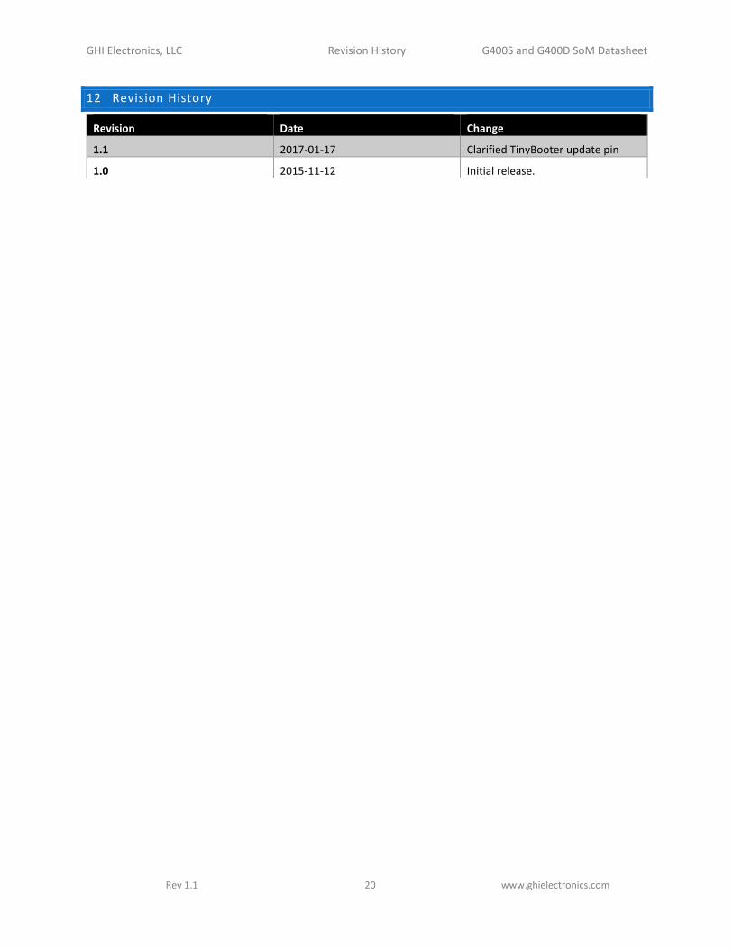
12 Revision History
Revision Date Change
1.1 2017-01-17 Clarified TinyBooter update pin
1.0 2015-11-12 Initial release.