Embed Size (px)
Citation preview

INSTRUCTION MANUAL
Read and understand all of the instructions and safety information in this manual before operating or servicing this tool.
Register this product at www.greenlee.com52063472 REV 4 © 2014 Greenlee Textron Inc. 12/14
G3 Tugger® System

G3 Tugger® System
Greenlee / A Textron Company 4455 Boeing Dr. • Rockford, IL 61109-2988 USA • 815-397-70702
Description
The Greenlee G3 Tugger® Cable Pulling System is intended to pull cable through conduit for light-duty applications.
Safety
Safety is essential in the use and maintenance of Greenlee tools and equipment. This instruction manual and any markings on the tool provide information for avoiding hazards and unsafe practices related to the use of this tool. Observe all of the safety information provided.
Purpose of this Manual
This manual is intended to familiarize all personnel with the safe operation and maintenance procedures for the Greenlee G3 Tugger® Cable Pulling System.
Keep this manual available to all personnel.
Replacement manuals are available upon request at no charge at www.greenlee.com.
All specifications are nominal and may change as design improvements occur. Greenlee Textron Inc. shall not be liable for damages resulting from misapplication or misuse of its products.
G3 Tugger is a registered trademark of Textron Innovations Inc.
® Registered: The color green for cable pulling equipment is a registered trademark of Textron Innovations Inc.
KEEP THIS MANUAL
Table of Contents
Description .................................................................... 2
Safety ............................................................................ 2
Purpose of this Manual ................................................. 2
General Safety Rules ..................................................... 3
Specific Safety Rules and Symbols ........................... 4-6
Grounding Instructions .................................................. 6
FUNCTIONAL DESCRIPTION
Identification .............................................................. 7
Specifications ............................................................ 8
Planning the Pull ........................................................ 8
ASSEMBLY
Boom Assembly/Disassembly ................................... 9
Boom Setup ........................................................ 10-11
Typical Setup for an Up Pull ................................. 11
Typical Setup for a Down Pull .............................. 11
Typical Setup for a Side Pull ................................ 11
OPERATION
Nose Assembly Operation ....................................... 12
Boom Operation ...................................................... 12
Handle Operation ..................................................... 12
Pivoting the Elbow and Nose Units ......................... 13
Puller Operation ....................................................... 14
SERVICE
Maintenance ............................................................ 15
ILLUSTRATIONS AND PARTS LISTS
G3 Tugger® Cable Pulling System .......................... 16
Head Assembly ........................................................ 17
Mobile Carriage ....................................................... 17
Motor Assembly .................................................. 18-19

G3 Tugger® System
Greenlee / A Textron Company 4455 Boeing Dr. • Rockford, IL 61109-2988 USA • 815-397-70703
GENERAL SAFETY RULESWARNING! Read and understand all instructions. Failure to follow all instructions listed below may result in electric shock, fire, and/or serious personal injury.
SAVE THESE INSTRUCTIONS
WORK AREA SAFETY
Keep your work area clean and well lit. Cluttered benches and dark areas invite accidents.
Do not operate power tools in explosive atmo-spheres, such as in the presence of flammable liquids, gases, or dust. Power tools create sparks which may ignite the dust or fumes.
Keep bystanders, children, and visitors away while operating a power tool. Distractions can cause you to lose control.
ELECTRICAL SAFETY
Grounded tools must be plugged into an outlet prop-erly installed and grounded in accordance with all codes and ordinances. Never remove the grounding prong or modify the plug in any way. Do not use any adapter plugs. Check with a qualified electrician if you are in doubt as to whether the outlet is properly grounded. If the tools should electrically malfunction or break down, grounding provides a low resistance path to carry electricity away from the user.
Avoid body contact with grounded surfaces such as pipes, radiators, ranges, and refrigerators. There is an increased risk of electric shock if your body is grounded.
Do not expose power tools to rain or wet conditions. Water entering a power tool will increase the risk of electric shock.
Do not abuse the cord. Never use the cord to carry the tools or pull the plug from an outlet. Keep cord away from heat, oil, sharp edges or moving parts. Replace damaged cords immediately. Damaged cords increase the risk of electric shock.
When operating a power tool outside, use an outdoor extension cord marked “W-A” or “W.” These cords are rated for outdoor use and reduce the risk of electric shock.
PERSONAL SAFETY
Stay alert, watch what you are doing and use common sense when operating a power tool. Do not use tool while tired or under the influence of drugs, alcohol, or medication. A moment of inattention while operating power tools may result in serious personal injury.
Dress properly. Do not wear loose clothing or jewelry. Contain long hair. Keep your hair, clothing, and gloves away from moving parts. Loose clothes, jewelry, or long hair can be caught in moving parts.
Avoid accidental starting. Be sure switch is off before plugging in. Carrying tools with your finger on the switch or plugging in tools that have the switch on invites accidents.
Remove adjusting keys or switches before turning the tool on. A wrench or a key that is left attached to a rotating part of the tool may result in personal injury.
Do not overreach. Keep proper footing and balance at all times. Proper footing and balance enables better control of the tool in unexpected situations.
Use safety equipment. Always wear eye protection. Dust mask, non-skid safety shoes, hard hat, or hearing protection must be used for appropriate conditions.
TOOL USE AND CARE
Use clamps or other practical way to secure and support the workpiece to a stable platform. Holding the work by hand or against your body is unstable and may lead to loss of control.
Do not force tool. Use the correct tool for your appli-cation. The correct tool will do the job better and safer at the rate for which it was designed.
Do not use tool if switch does not turn it on and off. Any tool that cannot be controlled with the switch is dangerous and must be repaired.
Disconnect the plug from the power source before making any adjustments, changing accessories, or storing the tool. Such preventive safety measures reduce the risk of starting the tool accidentally.
Store idle tools out of reach of children and other untrained persons. Tools are dangerous in the hands of untrained users.
Maintain tools with care. Keep cutting tools sharp and clean. Properly maintained tools, with sharp cutting edges, are less likely to bind and are easier to control.
Check for misalignment or binding of moving parts, breakage of parts, and any other condition that may affect the tool’s operation. If damaged, have the tool serviced before using. Many accidents are caused by poorly maintained tools.
Use only accessories that are recommended by the manufacturer for your model. Accessories that may be suitable for one tool may become hazardous when used on another tool.
SERVICE
Tool service must be performed only by qualified repair personnel. Service or maintenance performed by unqualified personnel could result in a risk of injury.
When servicing a tool, use only identical replace-ment parts. Follow instructions in the “Maintenance” section of this manual. Use of unauthorized parts or failure to follow maintenance instructions may create a risk of electric shock or injury.

G3 Tugger® System
Greenlee / A Textron Company 4455 Boeing Dr. • Rockford, IL 61109-2988 USA • 815-397-70704
SPECIFIC SAFETY RULES AND SYMBOLS
SAFETY ALERT SYMBOL
This symbol is used to call your attention to hazards or unsafe practices which could result in an injury or property damage. The signal word, defined below, indicates the severity of the hazard. The message after the signal word provides information for pre-venting or avoiding the hazard.
Immediate hazards which, if not avoided, WILL result in severe injury or death.
Hazards which, if not avoided, COULD result in severe injury or death.
Hazards or unsafe practices which, if not avoided, MAY result in injury or property damage.
Read and understand all of the instructions and safety information in this manual before operating or servicing this tool.
Failure to observe this warning will result in severe injury or death.
Do not operate the cable puller in a hazardous environment. Hazards include flammable liquids and gases.
Failure to observe this warning will result in severe injury or death.
Electric shock hazard:
Disconnect the cable puller from the power source before servicing.
Failure to observe this warning could result in severe injury or death.
Attach only to steel or schedule 40 PVC conduit. Do not attach to PVC conduit unless it is supported within 2" of the end.
Failure to observe this warning could result in severe injury or death.
Do not allow anything other than the pulling rope to contact the capstan. A grip, swivel, or other component could break and strike nearby personnel with great force.
Failure to observe this warning could result in severe injury or death.
Do not stand directly under a vertical pull. Cable could fall suddenly from the conduit, injuring nearby personnel.
Failure to observe this warning could result in severe injury or death.

G3 Tugger® System
Greenlee / A Textron Company 4455 Boeing Dr. • Rockford, IL 61109-2988 USA • 815-397-70705
SPECIFIC SAFETY RULES AND SYMBOLS
An under-rated or worn rope may break and whip violently. Use a polyester or polyester-jacketed rope with a breaking strength of 8000 pounds.
Failure to observe this warning could result in severe injury or death.
• Check the condition of the entire rope before use. A worn or damaged rope can break under tension and whip violently.
• Do not maintain a stationary rope on a rotating capstan. The wear generated may cause the rope to break under tension and whip violently.
Failure to observe these warnings could result in severe injury or death.
Attach the pulling rope to the cable with appropriate types of connectors. Select connectors with a rated capacity of 2000 pounds. An under-rated connector can break under tension.
Failure to observe this warning could result in severe injury or death.
Do not put fingers through holes in elbow unit. Rotating parts may cut off fingers.
Failure to observe this warning could result in severe injury or death.
Keep hands away from the capstan. Rope at the capstan can crush a hand.
Failure to observe this warning could result in severe injury or death.
Do not wrap rope around hands, arms, waist or other body parts. Do not stand in spent coils or tailed rope. Hold rope so that it may be released quickly.
Failure to observe this warning could result in severe injury or death.
Rope, cable, or a connecting device can break under tension, causing the rope to whip violently.
• Do not allow any unnecessary personnel to remain in the area during the pull.
• Do not allow any personnel to stand in line with the pulling rope.
Failure to observe these warnings could result in serious injury or death.
Do not allow the rope to overlap on the capstan. If the rope approaches the top of the angled part of the capstan, relax the tailing force. If an overlap does occur, shut off the puller immediately.
Failure to observe this warning could result in severe injury or death.
Tipping hazard:
Lower boom tubes to completely collapsed state before transporting the cable puller.
Failure to observe this warning could result in severe injury or death.

G3 Tugger® System
Greenlee / A Textron Company 4455 Boeing Dr. • Rockford, IL 61109-2988 USA • 815-397-70706
SPECIFIC SAFETY RULES AND SYMBOLS
Do not operate the puller without the guards in place.
Failure to observe this warning could result in severe injury or death.
Use this tool for manufacturer’s intended purpose only. Do not use the cable puller as a hoist or winch.
• The cable puller cannot lower a load.
• The load may fall.
Failure to observe this warning could result in severe injury or death.
Entanglement hazard:
• Do not operate the cable puller while wearing loose-fitting clothing.
• Retain long hair.
Failure to observe these warnings could result in severe injury or death.
Wear eye protection when using this tool.
Failure to wear eye protection could result in severe eye injury from flying debris.
Grounding Instructions
Electric shock hazard:
• Do not modify the plug provided with the tool.
• Connect this tool to a grounded receptacle on a 15-amp GFCI-protected circuit.
Failure to observe these warnings could result in severe injury or death.
This tool must be grounded. In the event of a malfunc-tion or breakdown, an electrical ground provides a path of least resistance for the electric current. This path of least resistance is intended to reduce the risk of electric shock.
This tool’s electric cord has a grounding conductor and a grounding plug as shown. Do not modify the plug. Connect the plug to a corresponding GFCI-protected receptacle that is properly installed and grounded in accordance with all national and local codes and ordinances.
Do not use an adapter.
NEMA 5-15
ReceptaclePlug

G3 Tugger® System
Greenlee / A Textron Company 4455 Boeing Dr. • Rockford, IL 61109-2988 USA • 815-397-70707
FUNCTIONAL DESCRIPTION
Identification
G3 Cable Pulling System
1. Nose Assembly
2. Ring Pull Detent Pin
3. Handle
4. Clamp Assembly
5. Sheave
6. Detent Pin
7. Top Extension Boom Tube
8. Mid Extension Boom Tube
9. Ring Pull Detent Pin
10. Motor Adapter Assembly
11. Hitch Clip
12. Motor Assembly
13. Power Cord
14. Motor
15. Circuit Breaker and Switch
16. Dolly Base Assembly
17. Two-Speed Capstan
18. Motor Attachment
19. Right Angle Sheave
1
10
11
1213
14
15
18
19
7
8
17
16
9
2
3
6
5
4

G3 Tugger® System
Greenlee / A Textron Company 4455 Boeing Dr. • Rockford, IL 61109-2988 USA • 815-397-70708
SpecificationsWeight .......................................................................................................123 lb (56 kg)
Dimensions
Length ................................................................................................. 1.4 ft (0.43 m)
Width ................................................................................................. 1.95 ft (0.59 m)
Height .................................................................................................. 4.5 ft (1.37 m)
Motor ............................................................................... 120 VAC, 50/60 Hz, 12 amps
Speed (high)
No Load..................................................................................... 97 ft/min (30 m/min)
500 lb ........................................................................................ 59 ft/min (18 m/min)
1000 lb ...................................................................................... 36 ft/min (11 m/min)
Speed (low)
No Load..................................................................................... 41 ft/min (12 m/min)
1000 lb ........................................................................................ 21 ft/min (6 m/min)
2000 lb (intermittent – 5 min on, 20 min off) ................................ 13 ft/min (4 m/min)
Puller Operation—Capstan
Low Speed ....................................................................................................5 wraps
High Speed ...................................................................................................4 wraps
Pulling Rope ........................................................1/2" double-braided composite rope 10,000 lb average breaking strength
Planning the Pull
• Pull in a direction that will require the lowest amount of pulling force.
• Plan several shorter pulls rather than fewer longer pulls.
• Locate the puller as close to the end of the conduit as possible to minimize the amount of exposed rope under tension.
• Place each component so that the pulling forces are used effectively.
• Select an anchoring system: adapter sheaves, which are preferred, or the floor mount.
• Verify that each component has the proper load rating.
• Inspect the structural supports. Verify that they have enough strength to withstand the maximum forces that may be generated.

G3 Tugger® System
Greenlee / A Textron Company 4455 Boeing Dr. • Rockford, IL 61109-2988 USA • 815-397-70709
ASSEMBLY
Boom Assembly/Disassembly
1. Set the base of the dolly on the ground where it is flat and has a strong base structure.
2. Insert the motor adapter assembly into the dolly. Make sure to insert the motor mount as shown in Figure 2. Attach and lock it with the pin.
3. Slide in the mid exten-sion and top extension boom tubes as shown in Figure 3. Make sure all the ring pull detent pins engage with the other tubes.
4. Slide the nose unit into the top extension boom tube using the ring pull detent pin.
5. Finally, attach the motor assembly unit to the motor adapter assembly as shown in Figure 5, using two clevis pins to lock it in place.
Tip: Lay the entire assembly on the ground to make it easier to insert the motor assembly unit.
Note: Lower boom tubes to completely collapsed state as shown in Figure 5 before transporting the cable puller.
Figure 1
Figure 2
Figure 3 Figure 5
Figure 4

G3 Tugger® System
Greenlee / A Textron Company 4455 Boeing Dr. • Rockford, IL 61109-2988 USA • 815-397-707010
Boom Setup
1. Place puller in approximate position of conduit.
2. Align nose with conduit and lock it in place with long detent pin.
3. Butt nose up against conduit threads and conduit locking nut. Place clamping plate inside of conduit and tighten knurled nut. Take lock nut off temporar-ily for more thread engagement if needed.
4. If the conduit is free standing or without threads, position the nose so that the conduit will butt up against the flats of the clamping plate.

G3 Tugger® System
Greenlee / A Textron Company 4455 Boeing Dr. • Rockford, IL 61109-2988 USA • 815-397-707011
Boom Setup (cont’d)
Typical Setup for a Side Pull
Typical Setup for an Up Pull Typical Setup for a Down Pull

G3 Tugger® System
Greenlee / A Textron Company 4455 Boeing Dr. • Rockford, IL 61109-2988 USA • 815-397-707012
OPERATION
Nose Assembly Operation
Refer to the illustration below.
1. Pull out the ring pull detent pin (1).
2. Rotate the nose assembly to the correct position for the pull.
3. Make sure the ring pull detent pin (1) is engaged with the circle tube.
Boom Operation
Refer to the illustration below.
Raising the BoomMake sure to raise the top extension first before raising the mid extension.
Note: When raising either extension, stop when the paint color changes from green to silver. Do not raise the extensions past the fourth hole from the end as shown here.
1. Pull out the ring pull detent pin (2).
2. Extend the top extension to the correct height.
3. Pull out the ring pull detent pin (3).
4. Extend the mid extension to the correct height.
5. Make sure the ring pull detent pins (2, 3) are engaged with the boom tubes.
Lowering the Boom1. Hold the boom tube with one hand. Be aware of the
weight.
2. Lift up the boom tube slightly and pull out the ring pull detent pin.
3. Move the boom tube to the correct height while pulling the ring pull detent pin. DO NOT allow the boom tube to drop freely.
4. When the correct height is reached, make sure the ring pull detent pin is engaged with the boom tube.
Handle Operation
Refer to the illustration below.
Rotating the Handles1. Pull out the ring pull detent pins (4).
2. Rotate the handles to the next position.
3. Make sure the pins are engaged to the handle.
Nose Assembly
Ring Pull Detent Pin (2)
Ring Pull Detent Pin (3)
Ring Pull Detent Pin (1)
Handle
Ring Pull Detent Pin (4) Ring Pull Detent Pin (4)
Mid Extension Boom Tube
Top Extension Boom Tube
Setting the Handle HeightChanging the boom tube height also changes the handle height. Refer to “Boom Operation” above for more information.
Green
Silver

G3 Tugger® System
Greenlee / A Textron Company 4455 Boeing Dr. • Rockford, IL 61109-2988 USA • 815-397-707013
Pivoting the Elbow and Nose Units
The elbow and nose units are physically identical and can be used interchangeably. For the sake of clarity, in this manual:
• “Nose” refers to the unit that attaches to the conduit via couplers.
• “Elbow” refers to the unit that connects the circle tubes.
The elbow/nose units pivot and lock at various degrees of rotation. They are locked in place by a detent pin set located between the sheave and the end of the boom tube receptacle. To pivot, squeeze the grips on the detent pins fully inward.
Squeeze
Grips
Make sure the detent pins on both sides are fully retracted before trying to pivot. Release the grips when the desired pivot angle is reached, and pivot slightly more to allow both detents to engage in the closest holes.
When the detent pins are squeezed to the fully inward position, they can be locked in place by twisting them counterclockwise.
Twist to lock.
Never pull cable with the detent pins locked inward; both the elbow and nose must be locked from pivoting before pulling.

G3 Tugger® System
Greenlee / A Textron Company 4455 Boeing Dr. • Rockford, IL 61109-2988 USA • 815-397-707014
Puller Operation
After fishing the rope through the conduit, wind it around the capstan. The puller will pull at two different speeds depending on whether the rope is on the large or small diameter. To pull at the lower speed, place the rope at the inner most part of the smaller capstan diameter and wind the rope clockwise and outward. To pull faster, do the same on the large diameter section of the capstan.
Low Speed
High Speed
When ready to start pulling cable, use only a few wraps of rope on the capstan at first. Using too many wraps will reduce your ability to control the rope on the capstan. Use the right angle sheave to position yourself so you are not in line with the high-tension rope in case it, the cable or the connector breaks.
Turn on the puller and gradually apply a tailing force to the free end of the rope. If the tailing force becomes uncomfortably high, turn off the puller and add another wrap. If the rope starts climbing up the inside ramp of the capstan, ease up in the tailing force to allow it to settle down to the base diameter. If it is continually climbing up the ramp, turn off the puller and remove a wrap.

G3 Tugger® System
Greenlee / A Textron Company 4455 Boeing Dr. • Rockford, IL 61109-2988 USA • 815-397-707015
Tool service must be performed only by qualified repair personnel. Service or maintenance performed by unqualified personnel could result in a risk of injury.
When servicing a tool, use only identical replace-ment parts. Follow instructions in the “Maintenance” section of this manual. Use of unauthorized parts or failure to follow maintenance instructions may create a risk of electric shock or injury.
Maintenance
Shut off motor and unplug unit before dismantling or servicing.
Failure to observe this warning will result in severe injury or death.
Drive Chains
Removal
Remove the 6 screws securing the chain guards. Slide out the chain guards—motor end first—and remove. Remove the bolt securing the capstan to the puller and the screw securing the drive sprocket to the motor. Remove all the washers, noting their proper order for reassembly. Pry off the drive sprocket while pulling out on the capstan unit and remove both. Pull off the drive chain. Reassemble with the connecting link retainer facing outward.
Wear
Check to make sure all the links pivot freely without binding. Replace the chain if any resistance is felt. Alternately load the links in tension and compression along the length to check for any perceptible free play. There should be a barely detectable amount of free play. If any joint has enough free play to be easily seen (about 1/64"), replace the chain. Always replace the entire chain, including the connecting link as a whole unit.
Lubrication
Lubricate the drive chains after every 40 hours of operation. Lubricate between the chain plates from the inside of the loop with any high quality chain lube or an 80W–90W gear oil.
Adjustment
Loosen the 4 screws securing the motor. Push the motor away from the capstan while retightening the motor screws.
Capstan
Removal
See drive chain removal.
Wear
Check for wear on the outside of the capstan. If the rope has worn a groove on the 2" diameter portion of the capstan, replace it. Check for bearing wear. If the brass bearing ID exceeds 1.020" or if there is visible radial free play between the capstan and shaft, replace the capstan and bearing assembly.
Lubrication
Lubricate the capstan shaft after every 20 hours of operation. Liberally apply a multipurpose NLGI grade 2 grease to the capstan shaft and bearing.
Adjustment
If the capstan or puller frame is replaced, adjust the axial free play to less than 1/32". Assemble the inner thrust washers and capstan to the frame without the chain. Attach with the bolt and retaining flat washer. If the capstan binds, add 52023123 shim washers one at a time until it rotates freely. If it has more than 1/32" of axial free play, add 50179160 fiber washers to set the free play at less than 1/32".
Motor
Commutator Brushes
Check the commutator brushes after every 40 hours of operation. Remove the motor brush caps and brushes. Measure the brush lengths. If length of either brush is less than 3/8", replace both brushes.
Other
Anti-Reverse Pawl
Check that the pawl pivots freely on its shaft. Clean any rust or debris from the shaft or pawl bore.
SERVICE

G3 Tugger® System
Greenlee / A Textron Company 4455 Boeing Dr. • Rockford, IL 61109-2988 USA • 815-397-707016
ILLUSTRATIONS AND PARTS LISTS
2
3
4
5
8
7
6
1
1 52066724 Nose assembly .....................................1
2 52066725 Tube extension, top weldment (painted) ................................................1
3 52066726 Tube extension, middle assembly.........1
4 52066727 Motor adapter assembly .......................1
5 Dolly base assembly .............................1
6 Motor assembly ....................................1
7 Clip, hitch pin ........................................3
8 Pin, clevis ..............................................3
52066173 Dolly assembly kit [includes 5, 7 (1), 8 (1)]
52066174 Motor assembly kit [includes 6, 7 (2), 8 (2)]
Key Part No. Description Qty
G3 Tugger® Cable Pulling System

G3 Tugger® System
Greenlee / A Textron Company 4455 Boeing Dr. • Rockford, IL 61109-2988 USA • 815-397-707017
ILLUSTRATIONS AND PARTS LISTS (cont’d)
1 52066729 Dolly bottom plate weldment ...............1
2 Wheel ....................................................2
3 Clip, hitch pin ........................................2
52066178 Wheel assembly kit (includes 2, 3)
1 52066728 Nose weldment .....................................1
2 Nose weldment, hinged ........................1
3 Clamp weldment assembly ..................1
4 Spring, compression, .53 x .66 x 1.25 (H6245A) .....................1
5 Nut ........................................................1
6 Nut, acorn-light, 3/8-16 ........................1
7 Sleeve detent, black oxide....................1
8 Detent, black oxide ...............................2
9 Grip detent, 0.187 .................................4
10 Pin, clevis, ø 1/2 x 4 ..............................2
11 Spring, compression, .177 ID x .329 OD x 1.410/1.420 L .......1
Key Part No. Description Qty
Key Part No. Description Qty Key Part No. Description Qty
Mobile Carriage
Head Assembly
3
21
13
1
3
4
5
6
9
8
1514
10
1617
18
2
11
12
7
12 Grip .......................................................2
13 52066741 Sheave ..................................................2
14 Rollpin, .187 x 2.00 ...............................2
15 Clip, hitch pin, ø .12 x 2.56 ...................2
16 Plunger ..................................................3
17 Spring, collar .........................................3
18 Ring, pull ...............................................3
52066177 Nose handle assembly kit (includes 2, 12)
52066175 Clamp assembly kit (includes 3–6)
52063080 Lock pin assembly kit (includes 7–9, 11, 14)
52066176 Spring-loaded pin assembly kit (includes one each of 16–18)
G3 Tugger® System
Greenlee / A Textron Company 4455 Boeing Dr. • Rockford, IL 61109-2988 USA • 815-397-707018
15
67
89
11
10
17 24
16
1312
1814
2120
19
1
2
23
4
5
3
22
25
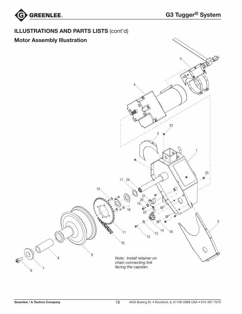
ILLUSTRATIONS AND PARTS LISTS (cont’d)
Motor Assembly Illustration
Note: Install retainer on chain connecting link facing the capstan.

G3 Tugger® System
Greenlee / A Textron Company 4455 Boeing Dr. • Rockford, IL 61109-2988 USA • 815-397-707019
Motor Assembly Parts List
1 52066885 Frame weldment assembly ...................1
2 Guard, chain (bottom) ...........................1
3 Guard, chain (top) .................................1
4 Gearmotor .............................................1
5 Electrical box assembly ........................1
6 Screw unit .............................................1
7 Cap, end ...............................................1
8 Spacer...................................................1
9 52066743 Capstan assembly ................................1
10 Chain, roller, #40, 1/2" pitch .................1
11 Sprocket, driver ....................................1
12 Screw, cap, #10-32 x 3/8 ......................1
13 Washer, flat, #10 x 5/8 OD ....................1
14 Sprocket ...............................................1
15 Screw, cap, sbh, 1/4-20 x 1.00 .............4
16 Washer, thrust .......................................2
Key Part No. Description Qty Key Part No. Description Qty
17 Washer, flat, 1.00 x 1.50 x .031 fiber ....1
18 Screw, cap, 1/4-20 x .625 hex hd .........4
19 Screw, cap, 1/4-20 x .500 skt hd ..........1
20 Ring, retaining, .500 Truarc #5100 EX...1
21 Pawl ......................................................1
22 Spring, torsion ......................................1
23 Screw, slftpg-phll hd, #10-16 x .250 .....6
24 Washer, shim, ø .5 ID x ø .75 OD x .031 ......................2
25 Nut, hex, 1/4-20 ....................................1
52066182 Motor guard assembly kit (includes 2, 3, 23)
52066181 Motor assembly kit (includes 4, 5)
52066179 Capstan unit assembly kit (includes 6–9, 16, 17)
52066180 Sprocket unit assembly kit (includes 10–15)
52066183 Pawl assembly kit (includes 19–22, 25)
52054433 Armature and field
52054434 Brush and cap
ILLUSTRATIONS AND PARTS LISTS (cont’d)

4455 Boeing Drive • Rockford, IL 61109-2988 • USA • 815-397-7070An ISO 9001 Company • Greenlee Textron Inc. is a subsidiary of Textron Inc.
USA Tel: 800-435-0786 Fax: 800-451-2632
Canada Tel: 800-435-0786 Fax: 800-524-2853
International Tel: +1-815-397-7070 Fax: +1-815-397-9247
www.greenlee.com