Embed Size (px)
Citation preview
GTX 3X5 Series Transponder G1000 Pilot’s Guide
© 2016 Garmin Ltd. or its subsidiaries. All rights reserved.
This manual reflects the operation of GTX 3X5 Series Transponders.
Garmin International, Inc., 1200 East 151st Street, Olathe, KS 66062, U.S.A.
Tel: 913/397.8200 Fax: 913/397.8282
Garmin AT, Inc., 2345 Turner Road SE, Salem, OR 97302, U.S.A.
Tel: 503/391.3411 Fax 503/364.2138
Garmin (Europe) Ltd., Liberty House, Bulls Copse Road, Hounsdown Business Park, Southampton, SO40 9LR, U.K.
Tel. +44 (0) 37 0850 1243 Fax +44 (0) 23 8052 4004
Garmin Singapore Pte. Ltd., 46 East Coast Road, #05-06 Eastgate, Singapore 428766
Tel: (65) 63480378 Fax: (65) 63480278
At Garmin, we value your opinion. For comments about this guide, please e-mail:
www.Garmin.com
Except as expressly provided herein, no part of this manual may be reproduced, copied, transmitted, disseminated,downloaded or stored in any storage medium, for any purpose without the express written permission of Garmin.Garmin hereby grants permission to download a single copy of this manual and of any revision to this manual onto ahard drive or other electronic storage medium to be viewed for personal use, provided that such electronic or printedcopy of this manual or revision must contain the complete text of this copyright notice and provided further that anyunauthorized commercial distribution of this manual or any revision hereto is strictly prohibited.
This document complies with Garmin Banned and Restricted Substances document, 001-00211-00.
Bluetooth® word mark and logos are registered trademarks owned by Bluetooth SIG, Inc. and any use of suchmarks by Garmin is under license.
Printed in the U.S.A
February 2016 190-01499-01 Rev. A
190-01499-01 Rev. A GTX 3X5 Series Transponder G1000 Pilot’s Guide i
Copyright InformationLIMITED WARRANTY
LIMITED WARRANTYAll Garmin avionics products are warranted to be free from defects in materials or workmanship for: two yearsfrom the date of purchase for new Remote-Mount and Panel-Mount products; one year from the date of purchasefor new portable products and any purchased newly-overhauled products; six months for newly-overhauledproducts exchanged through a Garmin Authorized Service Center; and 90 days for factory repaired or newly-overhauled products exchanged at Garmin in lieu of repair. Within the applicable period, Garmin will, at its soleoption, repair or replace any components that fail in normal use. Such repairs or replacement will be made at nocharge to the customer for parts or labor, provided that the customer shall be responsible for any transportationcost. This warranty does not apply to: (i) cosmetic damage, such as scratches, nicks and dents; (ii) consumableparts, such as batteries, unless product damage has occurred due to a defect in materials or workmanship; (iii)damage caused by accident, abuse, misuse, water, flood, fire, or other acts of nature or external causes; (iv)damage caused by service performed by anyone who is not an authorized service provider of Garmin; or (v)damage to a product that has been modified or altered without the written permission of Garmin. In addition,Garmin reserves the right to refuse warranty claims against products or services that are obtained and/or used incontravention of the laws of any country.
THE WARRANTIES AND REMEDIES CONTAINED HEREIN ARE EXCLUSIVE AND IN LIEU OF ALL OTHER WARRANTIES,WHETHER EXPRESS, IMPLIED OR STATUTORY, INCLUDING ANY LIABILITY ARISING UNDER ANY WARRANTY OFMERCHANTABILITY OR FITNESS FOR A PARTICULAR PURPOSE, STATUTORY OR OTHERWISE. THIS WARRANTY GIVESYOU SPECIFIC LEGAL RIGHTS, WHICH MAY VARY FROM STATE TO STATE.
IN NO EVENT SHALL GARMIN BE LIABLE FOR ANY INCIDENTAL, SPECIAL, INDIRECT OR CONSEQUENTIAL DAMAGES,WHETHER RESULTING FROM THE USE, MISUSE OR INABILITY TO USE THE PRODUCT OR FROM DEFECTS IN THEPRODUCT. SOME STATES DO NOT ALLOW THE EXCLUSION OF INCIDENTAL OR CONSEQUENTIAL DAMAGES, SO THEABOVE LIMITATIONS MAY NOT APPLY TO YOU.
Garmin retains the exclusive right to repair or replace (with a new or newly-overhauled replacement product) theproduct or software or offer a full refund of the purchase price at its sole discretion. SUCH REMEDY SHALL BEYOUR SOLE AND EXCLUSIVE REMEDY FOR ANY BREACH OF WARRANTY.
Online Auction Purchases: Products purchased through online auctions are not eligible for warranty coverage.Online auction confirmations are not accepted for warranty verification. To obtain warranty service, an original orcopy of the sales receipt from the original retailer is required. Garmin will not replace missing components fromany package purchased through an online auction.
International Purchases: A separate warranty may be provided by international distributors for devicespurchased outside the United States depending on the country. If applicable, this warranty is provided by the localin-country distributor and this distributor provides local service for your device. Distributor warranties are only validin the area of intended distribution. Devices purchased in the United States or Canada must be returned to theGarmin service center in the United Kingdom, the United States, Canada, or Taiwan for service. To obtain warranty service, contact your local Garmin Authorized Service Center. For assistance in locating aService Center near you, visit the Garmin website at:
http://www.garmin.com or contact Garmin Customer Service at 866-739-5687.
ii GTX 3X5 Series Transponder G1000 Pilot’s Guide 190-01499-01 Rev. A
WARNINGS / CAUTIONS / NOTES
WARNINGDo not use data link weather information for maneuvering in, near, or around areasof hazardous weather. Information contained within data link weather productsmay not accurately depict current weather conditions.
WARNINGDo not use the indicated data link weather product age to determine the age ofthe weather information shown by the data link weather product. Due to timedelays inherent in gathering and processing weather data for data link transmission,the weather information shown by the data link weather product may besignificantly older than the indicated weather product age.
WARNINGThis product, its packaging, and its components contain chemicals known to theState of California to cause cancer, birth defects, or reproductive harm. Thisnotice is being provided in accordance with California’s Proposition 65. If youhave any questions or would like additional information, please refer to ourwebsite at www.garmin.com/prop65/.
WARNINGTo reduce the risk of unsafe operation, carefully review and understand allaspects of the GTX 3X5 Pilot’s Guide. Thoroughly practice basic operation priorto actual use.
WARNINGTraffic information shown is provided as an aid in visually acquiring traffic.Pilots must maneuver the aircraft based only upon ATC guidance or positivevisual acquisition of conflicting traffic.
190-01499-01 Rev. A GTX 3X5 Series Transponder G1000 Pilot’s Guide iii
Copyright InformationWARNINGS / CAUTIONS / NOTES
CAUTIONUnauthorized repairs or modifications could result in permanentdamage to the equipment, and void your warranty and your authorityto operate this device under FCC and FAA regulations.
NOTEThe coverage expected for all operations (transponder replies to ATC,ADS-B and FIS-B reception) from the Garmin GTX 3X5 is limited to lineof sight. Low altitude or aircraft antenna shielding by the aircraft itselfmay result in reduced range. Range can be improved by climbing to ahigher altitude.
NOTEThis product does not contain any user-serviceable parts. Repairsshould only be made by an authorized Garmin service center.
NOTEIt is the responsibility of the GTX 3X5 owner, residing outside of theU.S., to obtain proper licensing before using the transponder.
iv GTX 3X5 Series Transponder G1000 Pilot’s Guide 190-01499-01 Rev. A
PRODUCT REGISTRATION AND SUPPORT
Product Registration and Support
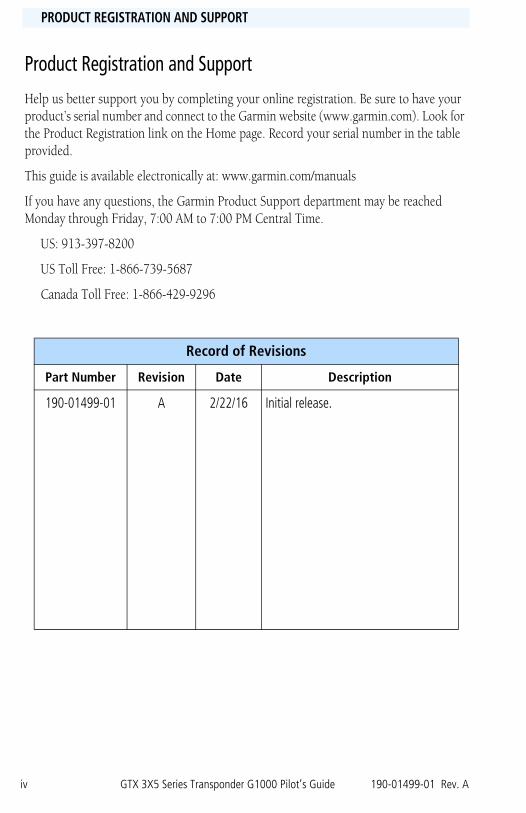
Help us better support you by completing your online registration. Be sure to have your product’s serial number and connect to the Garmin website (www.garmin.com). Look for the Product Registration link on the Home page. Record your serial number in the table provided.
This guide is available electronically at: www.garmin.com/manuals
If you have any questions, the Garmin Product Support department may be reached Monday through Friday, 7:00 AM to 7:00 PM Central Time.
US: 913-397-8200
US Toll Free: 1-866-739-5687
Canada Toll Free: 1-866-429-9296
Record of Revisions
Part Number Revision Date Description
190-01499-01 A 2/22/16 Initial release.
190-01499-01 Rev. A GTX 3X5 Series Transponder G1000 Pilot’s Guide v
Copyright InformationSOURCES AND RESOURCES
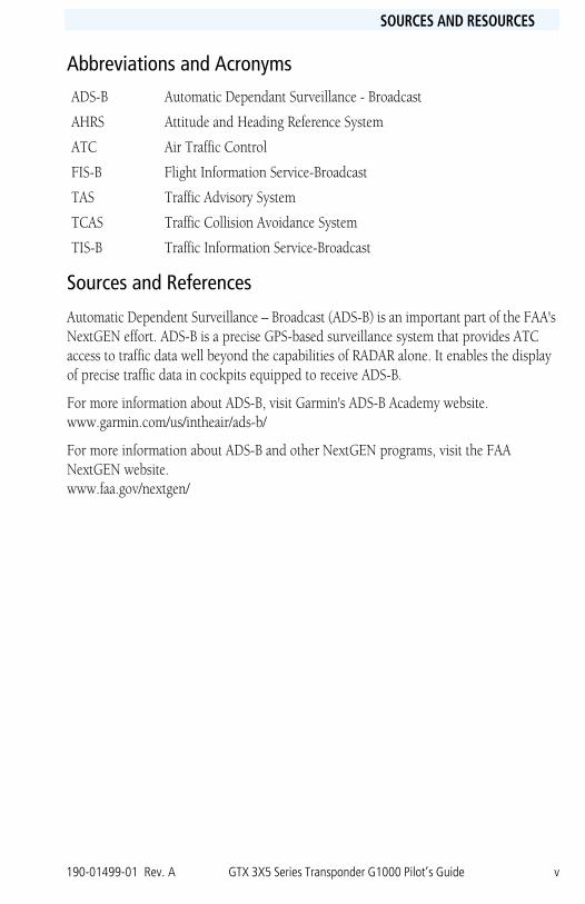
Abbreviations and Acronyms
Sources and References
Automatic Dependent Surveillance – Broadcast (ADS-B) is an important part of the FAA's NextGEN effort. ADS-B is a precise GPS-based surveillance system that provides ATC access to traffic data well beyond the capabilities of RADAR alone. It enables the display of precise traffic data in cockpits equipped to receive ADS-B.
For more information about ADS-B, visit Garmin's ADS-B Academy website.www.garmin.com/us/intheair/ads-b/
For more information about ADS-B and other NextGEN programs, visit the FAA NextGEN website.www.faa.gov/nextgen/
ADS-B Automatic Dependant Surveillance - Broadcast
AHRS Attitude and Heading Reference System
ATC Air Traffic Control
FIS-B Flight Information Service-Broadcast
TAS Traffic Advisory System
TCAS Traffic Collision Avoidance System
TIS-B Traffic Information Service-Broadcast

vi GTX 3X5 Series Transponder G1000 Pilot’s Guide 190-01499-01 Rev. A
This page intentionally left blank.
COPYRIGHT INFORMATION
190-01499-01 Rev. A GTX 3X5 Series Transponder G1000 Pilot’s Guide vii
Copyright InformationTABLE OF CONTENTS
1 GTX 3X5/G1000 Transponder Integration ................................................ 1-11.1 G1000 Mode Selection Key Modifications .........................................................1-21.2 System Modified Annunciations ........................................................................1-3
1.2.1 XPDR GND UNAVL Annunciation .............................................................1-41.2.2 ADS-B FAIL Annunciation .........................................................................1-5
FIGURESFigure 1-1 3X5/G1000 Transponder Soft Key Selections .................................... 1-2Figure 1-2 Annunciation Display ..........................................................................1-3Figure 1-3 XPDR GND UNAVL Annunciation Display..........................................1-4Figure 1-4 GND Mode Unavailable: CAS or Aircraft Alerts Window.....................1-5Figure 1-5 ADS-B Failure: CAS or Aircraft Alerts Window....................................1-5Figure 1-6 ADS-B Failure Alerts or Messages Window..........................................1-5
TABLESTable 1-1 Mode Selection Key Modifications ........................................................1-2
2 ADS-B In Traffic (345 Only) ...................................................................... 2-12.1 Traffic Integration and Operation .....................................................................2-1
2.1.1 Traffic Alerting ...........................................................................................2-22.1.2 No Bearing Traffic Alerting (Aural Only) ....................................................2-22.1.3 Traffic Annunciation ..................................................................................2-3
2.2 Traffic Picture ...................................................................................................2-4
FIGURES Figure 2-1 Display with ADS-B and TAS/TCAS.....................................................2-2Figure 2-2 Failed Annunciation on MFD Traffic Page and PFD Inset Map ............2-3Figure 2-3 No Data Annunciation on MFD Traffic Page and PFD Inset Map .........2-3
TABLESTable 2-1 GTX 345/GDL 90 Protocol Targets .......................................................2-4
3 FIS-B Weather and Flight Information (345 Only).................................... 3-13.1 Weather Source Selecting ..................................................................................3-2
TABLESTable 3-1 G1000 Supported FIS-B Weather Products ...........................................3-1

viii GTX 3X5 Series Transponder G1000 Pilot’s Guide 190-01499-01 Rev. A
This page intentionally left blank.
COPYRIGHT INFORMATION
190-01499-01 Rev. A GTX 3X5 Series Transponder G1000 Pilot’s Guide 1-1
Copyright Information1 – GTX 3X5/G1000 XPDR INTEGRATION
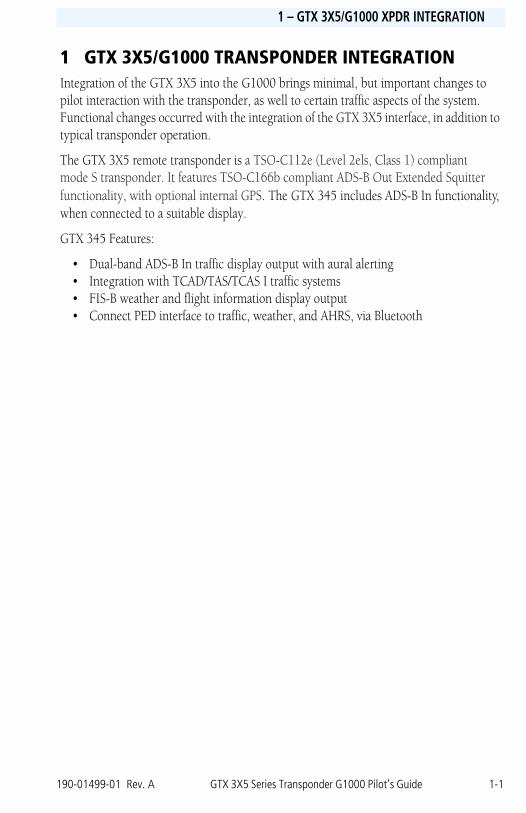
1 GTX 3X5/G1000 TRANSPONDER INTEGRATIONIntegration of the GTX 3X5 into the G1000 brings minimal, but important changes to pilot interaction with the transponder, as well to certain traffic aspects of the system. Functional changes occurred with the integration of the GTX 3X5 interface, in addition to typical transponder operation.
The GTX 3X5 remote transponder is a TSO-C112e (Level 2els, Class 1) compliant mode S transponder. It features TSO-C166b compliant ADS-B Out Extended Squitter functionality, with optional internal GPS. The GTX 345 includes ADS-B In functionality, when connected to a suitable display.
GTX 345 Features:
• Dual-band ADS-B In traffic display output with aural alerting• Integration with TCAD/TAS/TCAS I traffic systems• FIS-B weather and flight information display output• Connect PED interface to traffic, weather, and AHRS, via Bluetooth
1-2 GTX 3X5 Series Transponder G1000 Pilot’s Guide 190-01499-01 Rev. A
INTRODUCTION1 – GTX 3X5/G1000 XPDR INTEGRATION
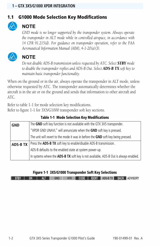
1.1 G1000 Mode Selection Key Modifications
NOTEGND mode is no longer supported by the transponder system. Always operatethe transponder in ALT mode while in controlled airspace, in accordance with14 CFR 91.215(d). For guidance on transponder operation, refer to the FAAAeronautical Information Manual (AIM), 4-1-20(a)(3).
NOTEDo not disable ADS-B transmission unless requested by ATC. Select STBY modeto disable the transponder replies and ADS-B Out. Select ADS-B TX soft key tomaintain basic transponder functionality.
When on the ground or in the air, always operate the transponder in ALT mode, unless otherwise requested by ATC. The transponder automatically determines whether the aircraft is in the air or on the ground and sends that information to other aircraft and ATC.
Refer to table 1-1 for mode selection key modifications. Refer to figure 1-1 for 3X5/G1000 transponder soft key sections.
Table 1-1 Mode Selection Key Modifications
Figure 1-1 3X5/G1000 Transponder Soft Key Selections
GND The GND soft key function is not available with the GTX 3X5 transponder.
“XPDR GND UNAVL” will annunciate when the GND soft key is pressed.
The unit will revert to the mode it was in before the GND soft key being pressed.
ADS-B TX Press the ADS-B TX soft key to enable/disable ADS-B transmission.
ADS-B defaults to the enabled state at system power-up.
In systems where the ADS-B TX soft key is not available, ADS-B Out is always enabled.
190-01499-01 Rev. A GTX 3X5 Series Transponder G1000 Pilot’s Guide 1-3
Copyright Information1 – GTX 3X5/G1000 XPDR INTEGRATION
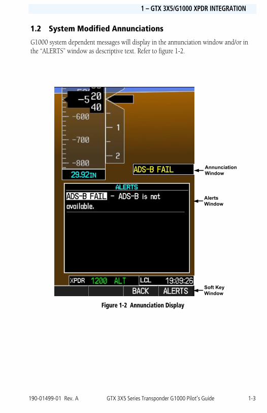
1.2 System Modified Annunciations
G1000 system dependent messages will display in the annunciation window and/or in the “ALERTS” window as descriptive text. Refer to figure 1-2.
Figure 1-2 Annunciation Display
Annunciation Window
Alerts Window
Soft Key Window
1-4 GTX 3X5 Series Transponder G1000 Pilot’s Guide 190-01499-01 Rev. A
INTRODUCTION1 – GTX 3X5/G1000 XPDR INTEGRATION
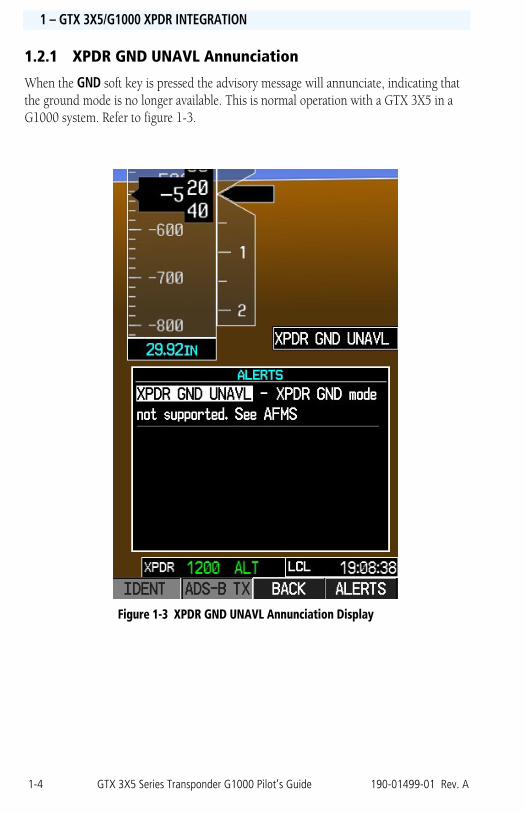
1.2.1 XPDR GND UNAVL Annunciation
When the GND soft key is pressed the advisory message will annunciate, indicating that the ground mode is no longer available. This is normal operation with a GTX 3X5 in a G1000 system. Refer to figure 1-3.
Figure 1-3 XPDR GND UNAVL Annunciation Display
190-01499-01 Rev. A GTX 3X5 Series Transponder G1000 Pilot’s Guide 1-5
Copyright Information1 – GTX 3X5/G1000 XPDR INTEGRATION
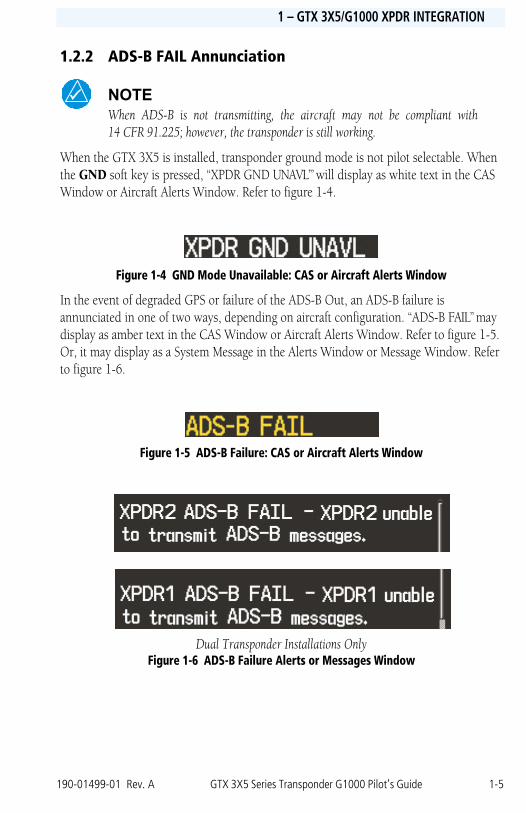
1.2.2 ADS-B FAIL Annunciation
NOTEWhen ADS-B is not transmitting, the aircraft may not be compliant with14 CFR 91.225; however, the transponder is still working.
When the GTX 3X5 is installed, transponder ground mode is not pilot selectable. When the GND soft key is pressed, “XPDR GND UNAVL’” will display as white text in the CAS Window or Aircraft Alerts Window. Refer to figure 1-4.
Figure 1-4 GND Mode Unavailable: CAS or Aircraft Alerts Window
In the event of degraded GPS or failure of the ADS-B Out, an ADS-B failure is annunciated in one of two ways, depending on aircraft configuration. “ADS-B FAIL” may display as amber text in the CAS Window or Aircraft Alerts Window. Refer to figure 1-5. Or, it may display as a System Message in the Alerts Window or Message Window. Refer to figure 1-6.
Figure 1-5 ADS-B Failure: CAS or Aircraft Alerts Window
Dual Transponder Installations OnlyFigure 1-6 ADS-B Failure Alerts or Messages Window

1-6 GTX 3X5 Series Transponder G1000 Pilot’s Guide 190-01499-01 Rev. A
This page intentionally left blank.
COPYRIGHT INFORMATION
190-01499-01 Rev. A GTX 3X5 Series Transponder G1000 Pilot’s Guide 2-1
Copyright Information2 – ADS-B IN TRAFFIC (345 ONLY)
2 ADS-B IN TRAFFIC (345 ONLY)
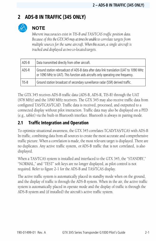
NOTEInherent inaccuracies exist in TIS-B and TAS/TCAS traffic position data. Because of this the GTX 345 may at times be unable to correlate targets from multiple sources for the same aircraft. When this occurs, a single aircraft is tracked and displayed as two co-located targets.
The GTX 345 receives ADS-B traffic data (ADS-B, ADS-R, TIS-B) through the UAT (978 MHz) and the 1090 MHz receivers. The GTX 345 may also receive traffic data from configured TAS/TCAS/TCAD. Traffic data is received, processed, and outputted to a connected display without pilot interaction. Traffic data may also be displayed on a PED (e.g., tablet) via the built-in Bluetooth interface. Bluetooth is always in pairing mode.
2.1 Traffic Integration and Operation
To optimize situational awareness, the GTX 345 correlates TCAD/TAS/TCAS with ADS-B In traffic, combining data from all sources to create the most accurate and comprehensive traffic picture. When a correlation is made, the most relevant target is displayed. There are no duplicates. Any active traffic system, or ADS-B traffic that is not correlated, is also displayed.
When a TAS/TCAS system is installed and interfaced to the GTX 345, the “STANDBY,” “NORMAL,” and “TEST” soft keys are no longer displayed, as pilot control is not required. Refer to figure 2-1 for the ADS-B and TAS/TCAS display.
The active traffic system is automatically placed in standby mode when on the ground, and the display of traffic is through the ADS-B system. When in the air, the active traffic system is automatically placed in operate mode and the display of traffic is through the ADS-B system and (if installed) the aircraft’s active traffic system.
ADS-B Data transmitted directly from other aircraft.
ADS-R Ground station rebroadcast of ADS-B data after data link translation (UAT to 1090 MHz or 1090 MHz to UAT). This function aids aircrafts only operating one frequency.
TIS-B Ground station broadcast of secondary surveillance radar (SSR) derived traffic.
2-2 GTX 3X5 Series Transponder G1000 Pilot’s Guide 190-01499-01 Rev. A
INTRODUCTION2 – ADS-B IN TRAFFIC (345 ONLY)
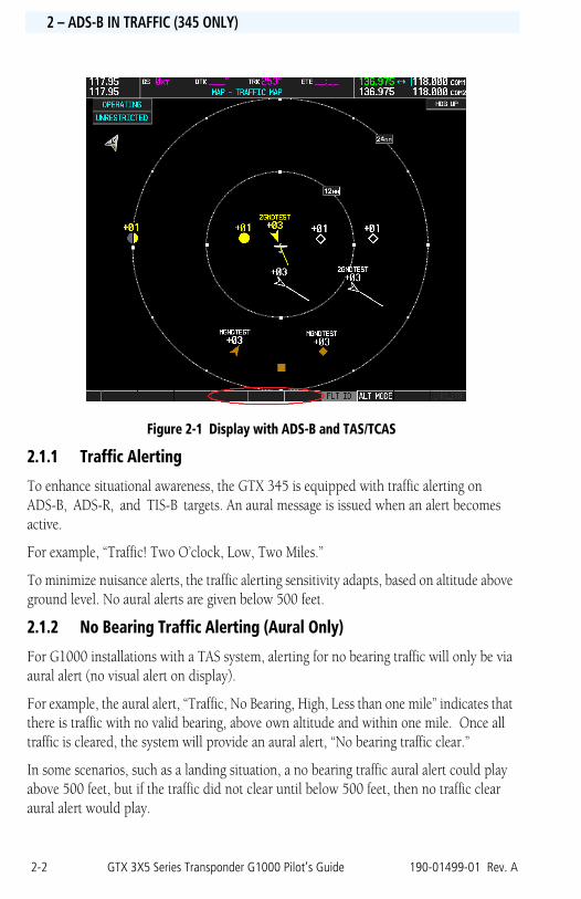
Figure 2-1 Display with ADS-B and TAS/TCAS
2.1.1 Traffic Alerting
To enhance situational awareness, the GTX 345 is equipped with traffic alerting on ADS-B, ADS-R, and TIS-B targets. An aural message is issued when an alert becomes active.
For example, “Traffic! Two O’clock, Low, Two Miles.”
To minimize nuisance alerts, the traffic alerting sensitivity adapts, based on altitude above ground level. No aural alerts are given below 500 feet.
2.1.2 No Bearing Traffic Alerting (Aural Only)
For G1000 installations with a TAS system, alerting for no bearing traffic will only be via aural alert (no visual alert on display).
For example, the aural alert, “Traffic, No Bearing, High, Less than one mile” indicates that there is traffic with no valid bearing, above own altitude and within one mile. Once all traffic is cleared, the system will provide an aural alert, “No bearing traffic clear.”
In some scenarios, such as a landing situation, a no bearing traffic aural alert could play above 500 feet, but if the traffic did not clear until below 500 feet, then no traffic clear aural alert would play.
190-01499-01 Rev. A GTX 3X5 Series Transponder G1000 Pilot’s Guide 2-3
Copyright Information2 – ADS-B IN TRAFFIC (345 ONLY)
2.1.3 Traffic Annunciation
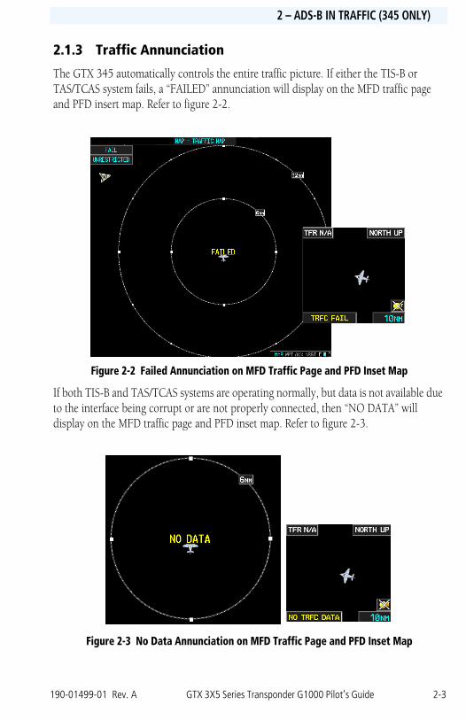
The GTX 345 automatically controls the entire traffic picture. If either the TIS-B or TAS/TCAS system fails, a “FAILED” annunciation will display on the MFD traffic page and PFD insert map. Refer to figure 2-2.
Figure 2-2 Failed Annunciation on MFD Traffic Page and PFD Inset Map
If both TIS-B and TAS/TCAS systems are operating normally, but data is not available due to the interface being corrupt or are not properly connected, then “NO DATA” will display on the MFD traffic page and PFD inset map. Refer to figure 2-3.
Figure 2-3 No Data Annunciation on MFD Traffic Page and PFD Inset Map
2-4 GTX 3X5 Series Transponder G1000 Pilot’s Guide 190-01499-01 Rev. A
INTRODUCTION2 – ADS-B IN TRAFFIC (345 ONLY)
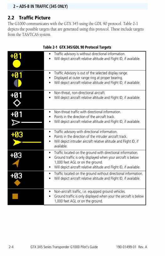
2.2 Traffic PictureThe G1000 communicates with the GTX 345 using the GDL 90 protocol. Table 2-1 depicts the possible targets that are generated using this protocol. These include targets from the TAS/TCAS system.
Table 2-1 GTX 345/GDL 90 Protocol Targets
• Traffic advisory is without directional information.• Will depict aircraft relative altitude and Flight ID, if available.
• Traffic Advisory is out of the selected display range.• Displayed at outer range ring at proper bearing.• Will depict aircraft relative altitude and Flight ID, if available.
• Non-threat, non-directional aircraft.• Will depict aircraft relative altitude and Flight ID, if available.
• Non-threat traffic with directional information.• Points in the direction of the aircraft track.• Will depict aircraft relative altitude and Flight ID, if available.
• Traffic advisory with directional information.• Points in the direction of the intruder aircraft track.• Will depict intruder aircraft relative altitude and Flight ID, if
available.
• Traffic located on the ground with directional information.• Ground traffic is only displayed when your aircraft is below
1,000 feet AGL or on the ground.• Will depict aircraft relative altitude and Flight ID, if available.
• Traffic located on the ground without directional information. • Will depict aircraft relative altitude and Flight ID, if available.
• Non-aircraft traffic, i.e. equipped ground vehicles.• Ground traffic is only displayed when your the aircraft is below
1,000 feet AGL or on the ground.
190-01499-01 Rev. A GTX 3X5 Series Transponder G1000 Pilot’s Guide 3-1
Copyright Information3 – FIS-B WEATHER / FLIGHT INFORMATION (345 ONLY)
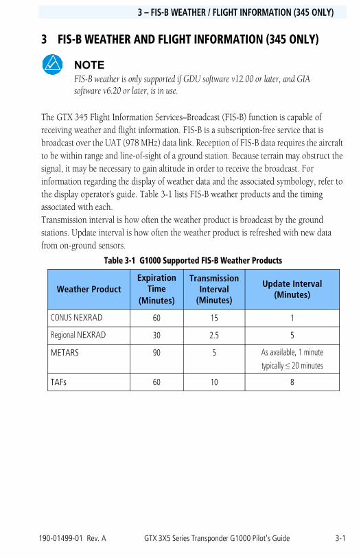
3 FIS-B WEATHER AND FLIGHT INFORMATION (345 ONLY)
NOTEFIS-B weather is only supported if GDU software v12.00 or later, and GIA software v6.20 or later, is in use.
The GTX 345 Flight Information Services–Broadcast (FIS-B) function is capable of receiving weather and flight information. FIS-B is a subscription-free service that is broadcast over the UAT (978 MHz) data link. Reception of FIS-B data requires the aircraft to be within range and line-of-sight of a ground station. Because terrain may obstruct the signal, it may be necessary to gain altitude in order to receive the broadcast. For information regarding the display of weather data and the associated symbology, refer to the display operator’s guide. Table 3-1 lists FIS-B weather products and the timing associated with each. Transmission interval is how often the weather product is broadcast by the ground stations. Update interval is how often the weather product is refreshed with new data from on-ground sensors.
Table 3-1 G1000 Supported FIS-B Weather Products
Weather ProductExpiration
Time (Minutes)
Transmission Interval
(Minutes)
Update Interval (Minutes)
CONUS NEXRAD 60 15 1
Regional NEXRAD 30 2.5 5
METARS 90 5 As available, 1 minute
typically ≤ 20 minutes
TAFs 60 10 8
3-2 GTX 3X5 Series Transponder G1000 Pilot’s Guide 190-01499-01 Rev. A
INTRODUCTION3 – FIS-B WEATHER / FLIGHT INFORMATION (345 ONLY)
3.1 Weather Source Selecting
The system uses the selected data link weather source for all maps the data link is displayed.
To View a Weather Data Link Page:
1. Turn the large FMS Knob to select the Map Page Group.
2. Turn the small FMS Knob to select the Weather Data Link (XM or FIS-B) Page.
To change the weather data link source:
3. Press the Menu Key.
4. Turn the small FMS Knob to select either “Display XM Weather” or “FIS-B Weather,” then press the ENT key.
© 2016 Garmin Ltd. or its subsidiaries
Garmin International, Inc.
1200 East 151st Street
Olathe, KS 66062, U.S.A.
Tel: 913/397.8200 Fax: 913/397.8282
Garmin AT, Inc.
2345 Turner Road SE
Salem, OR 97302, U.S.A.
Tel: 503/391.3411 Fax 503/364.2138
Garmin (Europe) Ltd.
Liberty House, Bulls Copse Road, Hounsdown Business Park
Southampton, SO40 9LR, U.K.
Tel. +44 (0) 37 0850 1243 Fax +44 (0) 23 8052 4004
Garmin Singapore Pte. Ltd.
46 East Coast Road #05-06 Eastgate, Singapore 428766
Tel: (65) 63480378 Fax: (65) 63480278
Part Number: 190-01499-01 Rev. A