Embed Size (px)
Citation preview

INSTALLATION, START-UP AND MAINTENANCE MANUAL
G1000 - GERMINATOR
®
256575R01


G1000 - GERMINATORINSTALLATION AND START-UP MANUAL
READ THESE INSTRUCTIONS CAREFULLY AND COMPLETELY
BEFORE OPERATING
Published by:
CONVIRON590 Berry Street
Winnipeg, ManitobaCanada R3H 0R9
www.conviron.com
March 2013
Copyright ©2013 Controlled Environments Limited. All rights reserved.


® i
SERVICE AND TECHNICAL SUPPORT
Guidelines
Conviron welcomes the opportunity to provide assistance and to answer any questions related to the start-up, use and general technical support and troubleshooting of equipment.
If problems arise while using Conviron chamber(s), refer to the relevant section in this manual to diagnose and correct the problem. If the problem persists and additional assistance is required, please collect the following information prior to contacting Conviron:
• The serial number of the chamber, which is located on the serial plate on the side of the chamber (see Figure 2.1).
• The software version of the CMP6010 Controller (see CMP6010 Operator’s Manual for information on how to determine software version)
• A description of the problem
• A description of what Operator(s) were doing before the problem occurred
Conviron Technical Services
North America Europe
Toll free +1.800.363.6451 +44.(0).800.032.6422
Telephone +1.204.786.6451 +44.(0).1638.781.731
Fax +1.204.786.7736 +44.1638.741.112


® iii
TABLE OF CONTENTS
SERVICE AND TECHNICAL SUPPORT ....................................................................... i
TABLE OF CONTENTS ..............................................................................................iii
1 PRECAUTIONS .................................................................................................. 1-1
1.1 Symbol Identification ....................................................................................... 1-1
1.2 Precautions ...................................................................................................... 1-1
2 G1000 OVERVIEW ............................................................................................. 2-1
3 PREPARATION, INSTALLATION AND START-UP .............................................. 3-1
3.1 Preparation ...................................................................................................... 3-1
3.1.1 Uncrating and Unpacking ...............................................................................3-1
3.1.2 G1000 Location parameters ...........................................................................3-1
3.1.2.1 Ambient Environmental Conditions .....................................................3-1
3.1.2.2 Power Supply .........................................................................................3-2
3.1.2.3 Water Supply ..........................................................................................3-2
3.1.2.4 Drain/Pump Connection (if required) ...................................................3-3
3.1.2.5 Communication ......................................................................................3-3
3.1.2.6 Central Alarm Contact (CAC) ................................................................3-3
3.2 Installation ...............................................................................................................3-3
3.2.1 Leveling ..........................................................................................................3-4
3.2.2 Connections ....................................................................................................3-4
3.2.2.1 Power Supply .........................................................................................3-4
3.2.2.2 Communication ......................................................................................3-5
3.2.2.3 Water Supply ..........................................................................................3-5
3.2.2.4 Drain ........................................................................................................3-5
3.2.2.5 Central Alarm Contact (CAC) ................................................................3-5
3.3 Start-up ........................................................................................................... 3-6
3.3.1 Fan Speed Control .........................................................................................3-6
3.3.2 Fresh Air Damper ...........................................................................................3-6
3.3.3 Instrument Port ..............................................................................................3-6

March 2013 | Rev 1.0iv
4 MAINTENANCE ................................................................................................ 4-1
4.1 Overview ......................................................................................................... 4-1
4.2 Procedures ...................................................................................................... 4-1
4.2.1 Daily Maintenance ..........................................................................................4-1
4.2.1.1 Temperature and Humidity ...................................................................4-1
4.2.1.2 Lights.......................................................................................................4-2
4.2.1.3 Drain Pan ................................................................................................4-2
4.2.2 Weekly Maintenance ......................................................................................4-2
4.2.2.1 Aspirator Wet Wick ................................................................................4-3
4.2.3 Monthly Maintenance .....................................................................................4-3
4.2.3.1 Ultrasonic Humidifier .............................................................................4-3
4.2.3.2 Air Cooled Condenser ..........................................................................4-4
4.2.4 Maintenance Every Three Months .................................................................4-5
4.2.4.1 Cleaning .................................................................................................4-5
4.2.4.2 Interior and Exterior Powder Coated Surfaces ....................................4-5
4.2.4.3 Bare Stainless Steel ................................................................................4-5
4.2.5 Maintenance Every Six Months ......................................................................4-6
4.2.5.1 Drain ........................................................................................................4-6
4.2.5.2 Preventative Maintenance .....................................................................4-6
5 TECHNICAL SPECIFICATIONS ......................................................................... 5-1

® 1-1
1 PRECAUTIONS
1.1 SYMBOL IDENTIFICATION
The following symbols are used throughout this manual and/or on your equipment to draw your attention to important warnings, guidelines and product information.
Hazard Warning Important Information
Dangerous Electrical Current Grounding Mark
Hot Surface
1.2 PRECAUTIONS
Please note the following information before operating or maintaining this equipment.
• This equipment is only to be operated and maintained by authorized personnel who have been trained on the proper operation and/or maintenance of the equipment and who have read this manual.
• If in doubt about safe operation and/or maintenance of the equipment, contact Conviron (see Page i: Service and Technical Support for contact information).
• Qualified trades people such as electricians, plumbers, and refrigeration mechanics should perform all work as required by local codes and regulations.
• Prior to operating or servicing, a visual inspection of the equipment and surrounding area should be conducted. Check both inside and outside to ensure no debris or obstacles are present that could pose a safety hazard. If operators see a potential hazard (e.g. water accumulating on the floor or an obstruction that would prevent the door from opening/closing properly) they should take appropriate steps such as alerting service personnel.

March 2013 | Rev 1.01-2
SECTION 1.0 | PRECAUTIONS
• Take all appropriate safety precautions when using and maintaining this equipment, including wearing appropriate safety apparel, using appropriate tools and utilizing fall protection equipment if working on elevated areas. Use only original replacement parts when maintaining the equipment.
• Electronic components in the control system can be damaged by electrostatic discharge (ESD). A substantial voltage can be discharged by the human body without necessarily feeling it, which is enough to destroy many electronic components. Use caution when servicing components in the machine compartment, as this voltage can damage sensitive electronics.
• Vibration during shipping can cause electrical and plumbing connections to loosen. Inspect all connections before connecting to main building services.
• To ensure no damage was incurred during transportation, operate your Conviron equipment for a minimum of two days before introducing any research material.
• The G1000 contains fluorescent lamps which are fragile and release harmful mercury vapors when broken. Allow five minutes for vapor to dissipate after opening the lamp canopy. Avoid direct contact with broken fluorescent lamps. Keep the lamp canopy doors locked at all times to avoid damage to the lamps. To dispose of lamps, follow the requirements in your area or contact your local authorities for procedures.
• Working with high voltage will be required when installing this equipment. Do not attempt electrical work without the appropriate knowledge and experience. Take appropriate safety precautions and ensure that the building power supply to the chamber is off prior to installation.
• The main terminal in the control panel has live voltage unless the external breaker is OFF. Use extreme caution when working in the control panel to prevent injury.
• Avoid water coming in contact with the electrical components, as it presents a risk of water damage to both high and low voltage electrical components and a shock hazard to operators and service personnel.
• Fluorescent lamps operate at high temperatures. Avoid touching the lamps at all times during operation. Wait 15 minutes for lamps to cool before servicing or replacement.

® 2-1
2 G1000 OVERVIEW
Figure 2.1: G1000 Key Features
Top Cover CMP6010 Interface
Fan Speed Control
Alarm Buzzer
Shelves
Aspirator Box
Main Power Switch
Canopy Vent Fan
Fluorescent Lamps
Canopy Door Lock
Serial Plate
* Unit may not be exactly as shown
March 2013 | Rev 1.02-2
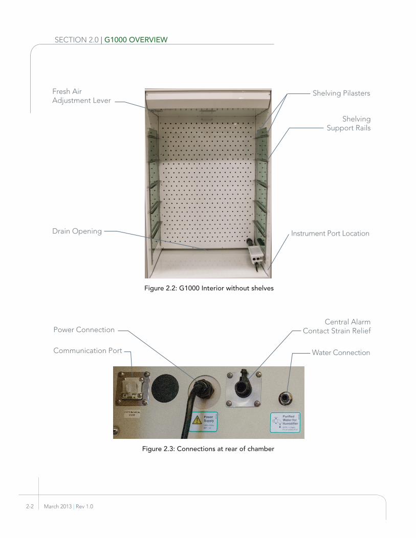
SECTION 2.0 | G1000 OVERVIEW
Figure 2.2: G1000 Interior without shelves
Figure 2.3: Connections at rear of chamber
Water Connection
Central Alarm Contact Strain Relief
Instrument Port Location
Fresh Air Adjustment Lever
Communication Port
Power Connection
Drain Opening
Shelving Pilasters
Shelving Support Rails

® 3-1
3 PREPARATION, INSTALLATION AND START-UP
3.1 PREPARATION
3.1.1 UNCRATING AND UNPACKING
1. Using a utility knife and pry bar, carefully remove packaging and then uncrate the G1000. Follow the instructions printed on the shipping pallet base to remove the chamber completely from its shipping crate
2. Verify all components according to the packing list. Notify your dealer or Conviron immediately of any missing components
3. Ensure the door and canopies are locked before moving the chamber to the installation location (see 3.1.2: G1000 Location Parameters for more information).
3.1.2 G1000 LOCATION PARAMETERS
The requirements listed below must be addressed in order to determine an suitable location for the G1000.
• Ambient environmental conditions
• Electrical/network connections
• Water supply
• Drain connection (if required)
• Central alarm contact (CAC).
3.1.2.1 Ambient Environmental Conditions
Ambient design conditions for the G1000 are 21ºC (70°F) and 50% relative humidity, however, the unit can tolerate an ambient temperature range of 15 - 30°C (59 - 86°F). Lower ambient temperature and relative humidity can negatively affect the capacity of the G1000 to reach the highest temperature and relative humidity set points. Higher ambient temperature and relative humidity can negatively affect the capacity of the G1000 to reach the lowest temperature and relative humidity set points.
A single G1000 will dissipate up to 1900 W to ambient as heat. It is critical that the area in which the G1000 is placed can accommodate the heat dissipated from the unit while maintaining a temperature range of 15 - 30°C (59 - 86°F). This heat is exhausted through the canopy vent openings and the rear wall of the machine compartment.

March 2013 | Rev 1.03-2
SECTION 3.0 | INSTALLATION AND START-UP
To ensure appropriate ventilation the G1000 requires the following clearances:
• A minimum of 12 in (300 mm) must be left clear behind the back wall
• A minimum of 12 in (300 mm) must be left clear above the unit
• A minimum of 4 in (100 mm) must be left clear on each side.
3.1.2.2 Power Supply
The G1000 is supplied with an attached 10 ft (3 m) power cord using two different connectors (for either 60 or 50 hz). The connection point is at the upper portion of the back of the cabinet (Figure 2.3).
The G1000 is single phase and offered in two voltage configurations. It is unsafe to use lines rate for lower amperage.
• 120 VAC/60 Hz (3 wires + ground). 20 A breaker required
• 230 VAC/50 Hz (3 wires + ground). 16 A breaker required
3.1.2.3 Water Supply
The G1000 provides added humidity using an ultrasonic humidifier (See Figure 3.1). This system requires purified supply water with the following properties:
• Connection: North America: 1⁄4 in compression (Yellow)
International: M6 compression (Blue)
• Pressure: 5 - 60 psi (0.3 - 4 bar)
• Max. Flow: 0.28 gph (1.1 l/hr)
• Water quality:
Ph: 7.0 ± 0.5
Filtration: <2 microns or 0.00008 in
Purity: Resistance: 0.0002 - 2.0 megohms
or
Conductivity: 0.5 - 5000 μSiemens
Figure 3.1: Ultrasonic Humidifier
Failure to use a water source with the quality stated above will increase the frequency of required maintenance.

® 3-3
3.1.2.4 Drain/Pump Connection (if required)
The G1000 utilizes a drain pan to collect excess moisture and condensation. It should be checked regularly and emptied as required to prevent overflow (frequency dependent on chamber set point conditions).
To avoid manually emptying the drain pan, the 1⁄2 in (13 mm) NPT(F) drain connection at the base of the G1000 (see Figure 3.2) can be connected to an open or tapped gravity drain. If no drain connection exists, an optional pump is available which automatically empties the drain pan. The pump is supplied with a 25 ft (7.6 m) length of hose to facilitate connection to a sink drain or larger reservoir.
3.1.2.5 Communication
The G1000 controller is shipped with a web card that allows direct connection to a computer for the retrieval of log data, or to a Conviron Central Management System. Connecting directly to a computer requires a crossover type ethernet cable, whereas connection to a Conviron Central Management system requires a straight through (peer to peer) type ethernet cable. The connection is made at the upper-rear of the unit (see Figure 2.3) to the Communication Port. Further information on functionality of the network connection can be found in the CMP6010 Operator’s Manual.
3.1.2.6 Central Alarm Contact (CAC)
The G1000 is equipped with a normally closed dry contact for connection to a remote monitoring system. When an alarm condition occurs, the normally closed contact opens, interrupting the circuit from the remote monitoring system to indicate an alarm.
3.2 INSTALLATION
The G1000 is shipped in one crate. To avoid damage, it is recommended that the unit remain crated until it is ready for placement in the facility. Proceed with caution if the unit must be removed from the crate. Ensure clearance through doorways, hallways, elevators, etc. See Section 5: Technical Specifications for exterior dimensions.
Figure 3.2: CAC Wiring Diagram
To Remote Monitoring
System

March 2013 | Rev 1.03-4
SECTION 3.0 | INSTALLATION AND START-UP
3.2.1 LEVELING
The G1000 is equipped with four threaded levelers that compensate for variations in floor level (see Figure 2.1). The levelers have 5⁄8 in (16 mm) wrench flats for adjustment, and a nut to lock the leveler once the chamber is level. The height of the levelers must be adjusted so the chamber rests on the levelers and not on the casters. Proceed as follows:
1. Adjust the levelers at the rear of the chamber until they are slightly higher than the casters
2. Adjust the levelers on the side walls until the gap between the caster and the floor is at least 1⁄8 in (3 mm) and no more than 1⁄4 in (6 mm)
3. Ensure the front of the G1000 is perfectly level side-to-side to allow the door to open/close properly.
Ensure that the four levelers are have firm contact with the floor. Ideally, the levelers in the front should be adjusted slightly higher than those in the back to facilitate drainage.
3.2.2 CONNECTIONS
Once the chamber is in position and leveled, the following connections must be made. Refer to Section 3.1.2: Chamber Placement Parameters for detailed requirements of each connection.
3.2.2.1 Power Supply
Before connecting the G1000 to electrical service, verify the service matches the requirements specified on the unit’s serial plate.
1. Insert the power cord plug into an appropriate receptacle. If the supplied plug is not suitable, replace it with one that meets both local electrical code and the requirements of the chamber
2. Ensure proper ground connection from the building electrical panel
3. Ensure neutral to ground voltage is within tolerance of <3 VAC
Figure 3.3: Caster and leveler
Figure 3.4: Serial Plate

® 3-5
3.2.2.2 Communication
To connect to the controller:
1. Connect an appropriate RJ45 ethernet cable to the communication port at the rear of the G1000
2. Connect directly to a computer or to an ethernet receptacle for the network on which the Conviron Central Management system resides. For more information on Conviron Central Management consult the Central Management Operator’s Manual or contact Conviron
Further information on functionality provided by a network connection can be found in the CMP6010 Operator’s Manual.
3.2.2.3 Water Supply
The G1000 provides additive humidity using an ultrasonic humidifier that requires between 5 to 60 psi (0.3 to 4 bar) pressure of purified supply water. Connect a 1⁄4 in (M6) water line to the compression fitting at the rear of the unit.
3.2.2.4 Drain
If a direct connection to a floor drain is desired:
1. Remove the drip pan at the bottom of the G1000
2. Connect a 1⁄2 in NPT(M) terminated hose to the 1⁄2 in NPT(F) drain connection at the bottom of the unit.
If using the optional drip pan pump:
1. Remove the drip pan from the bottom of the G1000
2. Connect the drain hose to the pump and place it in the drip pan
3. Replace the drip pan, routing the power cord toward the back of the unit, and the drain hose to the desired drain/reservoir
4. Connect the pump power cord to its power connection at the rear of the unit.
3.2.2.5 Central Alarm Contact (CAC)
Connection to the Central Alarm Contact requires access to the machine compartment. To make this connection:
Figure 3.6: Drain Connection
Figure 3.5: Communication Port

March 2013 | Rev 1.03-6
SECTION 3.0 | INSTALLATION AND START-UP
1. Turn off the main power switch
2. Remove the machine compartment top cover
3. Insert wires from the remote monitoring system through the strain relief collar at the rear of the machine compartment and connect them to terminal blocks C1 and C2.
4. Ensure there is slack in the wires between the terminal blocks. Tighten the screw on the strain relief collar (see Figure 3.7).
3.3 START-UPPress the main power button to turn the G1000 on. The switch will illuminate to indicate it is in the on position (see Figure 3.8)
In a few seconds the CMP6010 Controller will boot up. Once powered up, parameters in the controller must be set to control its operations. To learn how to adjust these parameters, refer to the CMP6010 Operators Manual.
3.3.1 FAN SPEED CONTROL
The G1000 uses a rotary knob for adjustment of fan speed (see Figure 3.9). Minimum fan speed is equivalent to 30% of maximum fan voltage which ensures air flow over the evaporator coil at all times.
3.3.2 FRESH AIR DAMPER
The G1000 is equipped with a damper for fresh air and exhaust air exchange (see Figure 3.10). A lever located inside the chamber cabinet adjusts the intake and exhaust air simultaneously. Before beginning an experiment, ensure the exhaust and fresh air adjustment lever is in the desired position using the label above the lever.
3.3.3 INSTRUMENT PORT
The G1000 has a 2 in (51 mm) instrument port with a slotted insulation puck (see Figure 3.11) that provides a path for cables, tubing and other related lines required for experimental equipment placed inside the chamber. The slotted design preserves the internal environmental conditions during an experiment.
Figure 3.7: CAC Strain Relief Collar
Figure 3.8: Main power switch
Figure 3.10: Fresh air damper lever
Figure 3.11: Instrument Port: Closed and Open
Figure 3.9: Fan speed control

® 4-1
4 MAINTENANCE
4.1 OVERVIEW
The G1000 requires minimal maintenance to ensure proper functioning. The following section outlines the timing and procedures for regular maintenance.
Maintenance may be required more frequently depending on the ambient conditions in which the G1000 is being operated and the type of experiments performed.
Before New Experiment
Daily Weekly Monthly 3 Months 6 Months
Temperature Humidity Lights
• • • • • •
Drain Pan • • • • • •
Aspirator Wet Wick • • • • •
Ultrasonic Humidifier • • • •
Air Cooled Condenser • • • •
Clean Chamber • • •
Drain • •
PM Contract Service •
4.2 PROCEDURES
4.2.1 DAILY MAINTENANCE
4.2.1.1 Temperature and Humidity
Temperature and humidity levels should be checked at the status screen of the CMP6010 display screen to ensure they correspond to the programmed set point values.
Figure 4.1: Maintenance Schedule

March 2013 | Rev 1.04-2
SECTION 4.0 | MAINTENANCE
4.2.1.2 Lights
Lamps should be checked to ensure they are functioning properly (i.e., no flickering, dim or unlit bulbs). This can be done simply by opening the front door. If a defective lamp is discovered, it should be replaced as soon as possible to ensure consistent lighting during experiments.
To replace a lamp:
1. Ensure the chamber power switch is in the OFF position and unplug the unit from its power receptacle
2. Unlock the canopy door (if required, the unit can be pulled forward to allow the canopy doors to open more than 30º for access)
3. Remove defective lamp by rotating it one-quarter turn and pulling forward to disengage it from the sockets
4. Insert new lamp into the empty sockets and rotate the lamp one-quarter turn to secure.
Fluorescent lamp type: 28 W/T5/841/ECO
Fluorescent lamps contain hazardous materials. Always follow local procedure and policy when disposing of hazardous materials.
4.2.1.3 Drain Pan
The chamber drain pan should be checked daily and emptied as required to prevent overflow.
4.2.2 WEEKLY MAINTENANCE
Figure 4.2: Lamp Socket
Fluorescent lamps contain hazardous materials. Always follow local procedure and policy when disposing of hazardous materials.
® 4-3
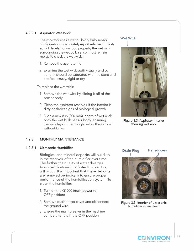
4.2.2.1 Aspirator Wet Wick
The aspirator uses a wet bulb/dry bulb sensor configuration to accurately report relative humidity at high levels. To function properly, the wet wick surrounding the wet bulb sensor must remain moist. To check the wet wick:
1. Remove the aspirator lid
2. Examine the wet wick both visually and by hand. It should be saturated with moisture and not feel crusty, rigid or dry.
To replace the wet wick:
1. Remove the wet wick by sliding it off of the sensor body
2. Clean the aspirator reservoir if the interior is dirty or shows signs of biological growth
3. Slide a new 8 in (200 mm) length of wet wick onto the wet bulb sensor body, ensuring the wick lays in the trough below the sensor without kinks.
4.2.3 MONTHLY MAINTENANCE
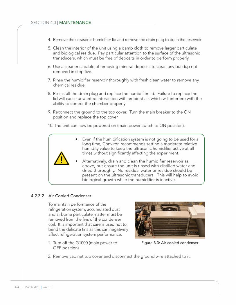
4.2.3.1 Ultrasonic Humidifier
Biological and mineral deposits will build up in the reservoir of the humidifier over time. The further the quality of water diverges from specifications, the faster this buildup will occur. It is important that these deposits are removed periodically to ensure proper performance of the humidification system. To clean the humidifier:
1. Turn off the G1000 (main power to OFF position)
2. Remove cabinet top cover and disconnect the ground wire
3. Ensure the main breaker in the machine compartment is in the OFF position
Figure 3.3: Interior of ultrasonic humidifier when clean
TransducersDrain Plug
Figure 3.3: Aspirator interior showing wet wick
Wet Wick
March 2013 | Rev 1.04-4
SECTION 4.0 | MAINTENANCE
4. Remove the ultrasonic humidifier lid and remove the drain plug to drain the reservoir
5. Clean the interior of the unit using a damp cloth to remove larger particulate and biological residue. Pay particular attention to the surface of the ultrasonic transducers, which must be free of deposits in order to perform properly
6. Use a cleaner capable of removing mineral deposits to clean any buildup not removed in step five.
7. Rinse the humidifier reservoir thoroughly with fresh clean water to remove any chemical residue
8. Re-install the drain plug and replace the humidifier lid. Failure to replace the lid will cause unwanted interaction with ambient air, which will interfere with the ability to control the chamber properly
9. Reconnect the ground to the top cover. Turn the main breaker to the ON position and replace the top cover
10. The unit can now be powered on (main power switch to ON position).
• Even if the humidification system is not going to be used for a long time, Conviron recommends setting a moderate relative humidity value to keep the ultrasonic humidifier active at all times without significantly affecting the experiment.
• Alternatively, drain and clean the humidifier reservoir as above, but ensure the unit is rinsed with distilled water and dried thoroughly. No residual water or residue should be present on the ultrasonic transducers. This will help to avoid biological growth while the humidifier is inactive.
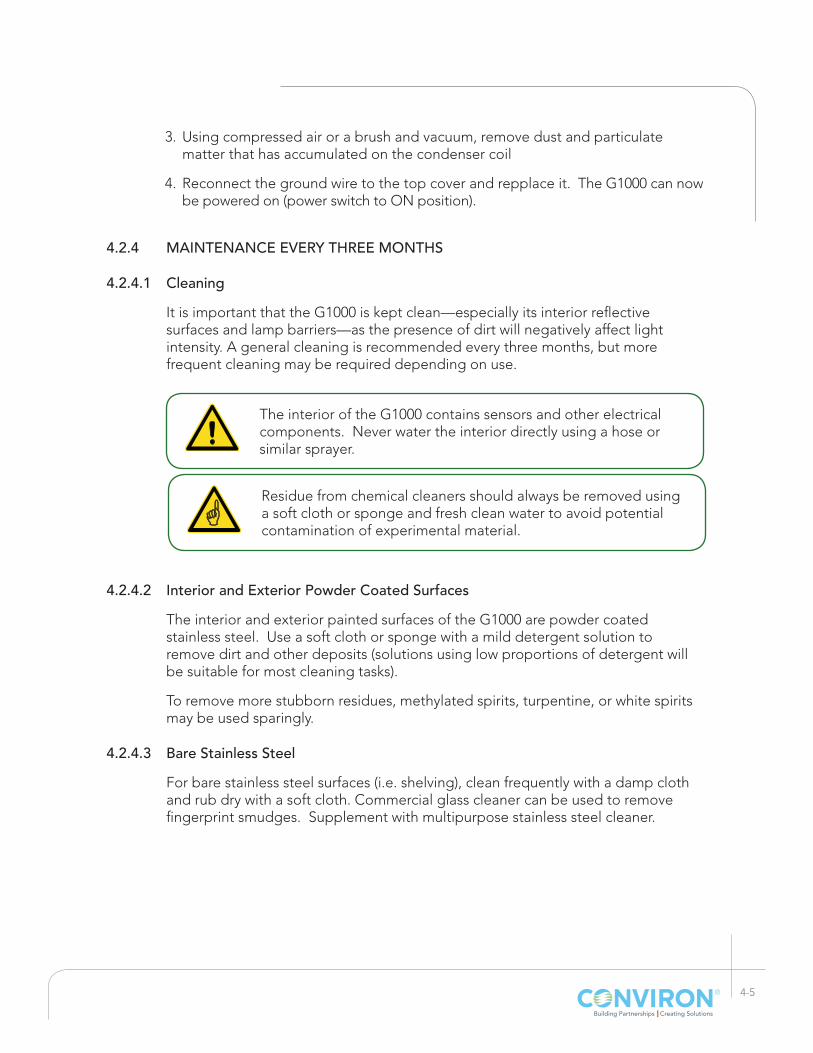
4.2.3.2 Air Cooled Condenser
To maintain performance of the refrigeration system, accumulated dust and airborne particulate matter must be removed from the fins of the condenser coil. It is important that care is used not to bend the delicate fins as this can negatively affect refrigeration system performance.
1. Turn off the G1000 (main power to OFF position)
2. Remove cabinet top cover and disconnect the ground wire attached to it.
Figure 3.3: Air cooled condenser
® 4-5
3. Using compressed air or a brush and vacuum, remove dust and particulate matter that has accumulated on the condenser coil
4. Reconnect the ground wire to the top cover and repplace it. The G1000 can now be powered on (power switch to ON position).
4.2.4 MAINTENANCE EVERY THREE MONTHS
4.2.4.1 Cleaning
It is important that the G1000 is kept clean—especially its interior reflective surfaces and lamp barriers—as the presence of dirt will negatively affect light intensity. A general cleaning is recommended every three months, but more frequent cleaning may be required depending on use.
The interior of the G1000 contains sensors and other electrical components. Never water the interior directly using a hose or similar sprayer.
4.2.4.2 Interior and Exterior Powder Coated Surfaces
The interior and exterior painted surfaces of the G1000 are powder coated stainless steel. Use a soft cloth or sponge with a mild detergent solution to remove dirt and other deposits (solutions using low proportions of detergent will be suitable for most cleaning tasks).
To remove more stubborn residues, methylated spirits, turpentine, or white spirits may be used sparingly.
4.2.4.3 Bare Stainless Steel
For bare stainless steel surfaces (i.e. shelving), clean frequently with a damp cloth and rub dry with a soft cloth. Commercial glass cleaner can be used to remove fingerprint smudges. Supplement with multipurpose stainless steel cleaner.
Residue from chemical cleaners should always be removed using a soft cloth or sponge and fresh clean water to avoid potential contamination of experimental material.

March 2013 | Rev 1.04-6
SECTION 4.0 | MAINTENANCE
4.2.5 MAINTENANCE EVERY SIX MONTHS
4.2.5.1 Drain
The drain should be inspected every six months to ensure the it is flowing properly. Pour a small amount of water—4 - 8 oz (250 - 500 ml)— on to the floor of the chamber near the drain opening. The water should drain in a timely fashion and show no signs of pooling.
If the water does not drain freely use a manual drain clog remover (drain snake) or similar device to ensure that the path from the drain inlet inside the chamber to the drain outlet at the base of the unit is free of obstructions. This may require temporarily disconnecting the chamber from a drain hose if connected directly to a floor drain.
4.2.5.2 Preventative Maintenance
Conviron recommends preventative maintenance checks of the refrigeration system every six months to keep the chamber performing optimally throughout the year. Preventative maintenance should be performed by a qualified service technician. Contact Conviron for additional information on preventative maintenance programs.

® 5-1
5 TECHNICAL SPECIFICATIONS
1.0 Control System: Conviron CMP6010
2.0 Construction: (Note: All dimensions are nominal.)2.1 Weight 880 lbs (400 kg)2.2 Exterior Dimensions: 45.5” W x 32.5” D x 79” H (1155 mm
W x 825 mm D x 2005 mm H)2.3 Interior Dimensions: 37” W x 25” D (940 mm W x 635 mm D)2.4 Interior Capacity: 35 ft³ (1000 litres)
2.6 Exterior Finish: Powder-coated steel2.7 Interior Finish: Reflective white powder-coated
stainless steel for scratch and corrosion resistance, long life, and ease of cleaning.
2.8 Trays: Five stainless steel trays 21.5” x 36” (546.1 mm x 914.4 mm) included with basic unit. Up to 15 additional trays optionally available.
2.10 Control Panel & Instrument Display Located above the chamber door.2.11 Casters: Heavy-duty, swivel. Adjustable level-
ers are provided to secure the unit3.0 Lighting:
3.1 Programming and Control: On/Off programming of lamps.
3.2 Barrier: Sealed double glass on both side walls.
3.3 Lamp Fixtures: Two exterior fixtures (one per side wall) each containing four (4) 28 W/T5/841/ECO fluorescent lamps per side.
3.4 Ballasts: High efficiency electronic for easy access, located at the canopy.
4.0 Temperature Control:
4.1 Range: +4°C to +40°C lights OFF/ON; (Maxi-mum design ambient temperature is +30°C)
1 Measured by Precision Thermistors, measured without test materials or optional accessories.

March 2013 | Rev 1.05-2
SECTION 5.0 | TECHNICAL SPECIFICATIONS
4.2 Control1: ±0.5°C at control point
4.3 Temperature Safety Limits: A programmable high and low tem-perature limit alarm. Safety tempera-ture limit factory preset independent from control system turns chamber off
5.0 Refrigeration:
5.1 Condensing Unit: Cabinet is supplied with a top mounted, air-cooled condensing unit with hot gas bypass system
5.2 Valve: Electronic modulating valve smoothly regulates the heating and cooling functions of the chamber.
5.3 Heat Exchanger Coil(s): Copper-tubed construction
5.4 Refrigerant: R134a (4.2 lbs)
5.5 Monitoring: Refrigeration system operation is monitored by the control system, in-cluding visual and audible alarm.
6.0 Air Flow:
6.1 Distribution: Air is directed horizontally from rear wall plenum providing uniform environmental conditions.
6.2 Fresh Air: Manually adjustable from inside the unit.
6.3 Fan Speed Control: Allows the user to control the speed of the circulating air, from 30 -100% of fan voltage.
7.0 Humidity Control:
7.1 Range: Up to 98% RH, limited by a +25°C dew point; (Based on +21°C and 50% RH ambient condition)
7.2 Programming: See Control System.
7.3 Control: ±3% RH. System uses a wet bulb sensor complete with wet sock. The controller converts the difference between wet and dry bulb readings and displays in % RH.
7.4 Ultrasonic Transducers Siansonic MU-360, 36VAC

® 5-3
8.0 Utility Requirements2: (Rating increases with some options.)
8.1 Electrical Service: 60 Hz: 120-1Ø-60 Hz – 2 wire plus ground – 20 Amp Overcurrent Protection
50 Hz: 220-240-1Ø-50 Hz - 2 wire plus ground – 16 Amp Overcurrent Protection
8.2 Cord Set: 60hz: NEMA 5-20p50hz: CEE 7/7
8.3 Water Supply: 1080 ml/hr = 1.1 l/hr = 0.28 gph / Pressure minimum: 5 psi, maximum 60 psi.
8.4 Drain: A ½” NPT(F) for rigid drain connection is provided at the front of the chamber. Floor drain must be provided outside footprint of cabinet.
8.5 Humidity System: Must be supplied with clean water to the following specification; pH = 7.0 ± 0.5, filtration <2 microns (0.00008 in) and resistivity between 0.5 and 1.0 Meg Ohms. Maximum water usage to maintain specified levels is 1.1 liters/hr.
8.6 CSA-C/US: Provided with product certification to both UL and CSA Standards by CSA International, or an equivalent Nationally Recognized Testing Laboratory (NRTL), for use in both the United States and Canada. Proof of product certification provided. Chambers listed on the CSA International Website as an approved product (http://directories.csa-international.org, search Controlled Environments)
9.0 Warranty and After Sales Service:
9.1 Warranty: 2 years; parts and labor
For more information refer to the warranty card included in the Welcome Kit or contact Conviron
2 This unit will tolerate ±10% voltage fluctuation from the rated voltage on the serial plate. A voltage stabilizer must be used if the fluctuation is greater than ±10%. Failure to do so can result in serious damage to the compressor and electronic components and will void warranty. Disconnect switch must be sized by a local qualified electrician.

CO
NV
IRO
N IS
AN
ISO
CE
RTI
FIE
D C
OM
PAN
Y
Head Office590 Berry Street | Winnipeg, MB | R3H 0R9tel 204.786.6451 | toll free 1.800.363.6451 | fax 204.786.7736
Sales OfficePO Box 347 | Pembina, ND | 58271toll free 1.800.363.6451 | fax 204.786.7736
Unit 1 Hall Barn Road Industrial Estate | Isleham, Cambridgeshire | CB7 5RB | Englandtel/fax +44 (0)1638 74 1112 | toll free +44 (0)800 032 6422
Wulfsheinstr. 6 | 10585 Berlin | Germany tel +49 (0) 30 - 315 05285 | fax +49 (0) 30 - 315 05286
Canada
USA
United Kingdom
Germany
®