Embed Size (px)
Citation preview

SCARA ROBOT
G10 / G20 series MANIPULATOR MANUAL
Rev.9 EM105R2012F

MA
NIP
ULATO
R M
AN
UA
L G10 / G
20 series Rev.9

G10 / G20 Rev.9 i
SCARA ROBOT
G10 / G20 series Manipulator Manual Rev.9
Copyright © 2007-2010 SEIKO EPSON CORPORATION. All rights reserved.

ii G10 / G20 Rev.9
FOREWORD Thank you for purchasing our robot products. This manual contains the information necessary for the correct use of the manipulator. Please carefully read this manual and other related manuals before installing the robot system. Keep this manual handy for easy access at all times.
WARRANTY The Manipulator and its optional parts are shipped to our customers only after being subjected to the strictest quality controls, tests, and inspections to certify its compliance with our high performance standards. Product malfunctions resulting from normal handling or operation will be repaired free of charge during the normal warranty period. (Please ask your Regional Sales Office for warranty period information.) However, customers will be charged for repairs in the following cases (even if they occur during the warranty period): 1. Damage or malfunction caused by improper use which is not described in the manual,
or careless use. 2. Malfunctions caused by customers’ unauthorized disassembly. 3. Damage due to improper adjustments or unauthorized repair attempts. 4. Damage caused by natural disasters such as earthquake, flood, etc.
Warnings, Cautions, Usage:
1. If the Manipulator or associated equipment is used outside of the usage conditions and
product specifications described in the manuals, this warranty is void. 2. If you do not follow the WARNINGS and CAUTIONS in this manual, we cannot be
responsible for any malfunction or accident, even if the result is injury or death. 3. We cannot foresee all possible dangers and consequences. Therefore, this manual
cannot warn the user of all possible hazards.

G10 / G20 Rev.9 iii
TRADEMARKS Microsoft, Windows, and Windows logo are either registered trademarks or trademarks of Microsoft Corporation in the United States and/or other countries. Other brand and product names are trademarks or registered trademarks of the respective holders.
NOTICE No part of this manual may be copied or reproduced without authorization. The contents of this manual are subject to change without notice. Please notify us if you should find any errors in this manual or if you have any comments regarding its contents.
INQUIRIES Contact the following service center for robot repairs, inspections or adjustments. If service center information is not indicated below, please contact the supplier office for your region.
Please prepare the following items before you contact us.
- Your controller model and its serial number - Your manipulator model and its serial number - Software and its version in your robot system - A description of the problem
SERVICE CENTER

iv G10 / G20 Rev.9
MANUFACTURER & SUPPLIER SEIKO EPSON CORPORATION
Japan & Others Suwa Minami Plant Factory Automation Systems Dept. 1010 Fujimi, Fujimi-machi, Suwa-gun, Nagano, 399-0295 JAPAN
TEL : +81-(0)266-61-1802 FAX : +81-(0)266-61-1846
SUPPLIERS North & South America EPSON AMERICA, INC. Factory Automation/Robotics
18300 Central Avenue Carson, CA 90746 USA
TEL : +1-562-290-5900 FAX : +1-562-290-5999 E-MAIL : [email protected] Europe EPSON DEUTSCHLAND GmbH Factory Automation Division
Otto-Hahn-Str.4 D-40670 Meerbusch Germany
TEL : +49-(0)-2159-538-1391 FAX : +49-(0)-2159-538-3170 E-MAIL : [email protected]

G10 / G20 Rev.9 v
For Customers in the European Union
The crossed out wheeled bin label that can be found on your product indicates that this product and incorporated batteries should not be disposed of via the normal household waste stream. To prevent possible harm to the environment or human health please separate this product and its batteries from other waste streams to ensure that it can be recycled in an environmentally sound manner. For more details on available collection facilities please contact your local government office or the retailer where you purchased this product. Use of the chemical symbols Pb, Cd or Hg indicates if these metals are used in the battery. This information only applies to customers in the European Union, according to DIRECTIVE 2006/66/EC OF THE EUROPEAN PARLIAMENT AND OF THE COUNCIL OF 6 September 2006 on batteries and accumulators and waste batteries and accumulators and repealing Directive 91/157/EEC and legislation transposing and implementing it into the various national legal systems. For other countries, please contact your local government to investigate the possibility of recycling your product. The battery removal/replacement procedure is described in the following manuals: Controller manual / Manipulator manual (Maintenance section)

vi G10 / G20 Rev.9
Before Reading This Manual This section describes what you should know before reading this manual.
Structure of Control System
The G10 / G20 series Manipulators can be used with the following combinations of Controllers and software.
The operating methods and descriptions are different depending on which software you are using. The following icons are put beside appropriate text as necessary. Use the descriptions that pertain to the software you are using.
Controller
Name Structure Software
RC180 Controller EPSON RC+ 5.0 Ver.5.2 or greater
RC620 Control Unit Drive Unit
EPSON RC+ 6.0 Ver. 6.0 or greater
For details on commands, refer to User’s Guide or “On-line help”.
Turning ON/OFF Controller When you see the instruction “Turn ON/OFF the Controller” in this manual, be sure to turn ON/OFF all the hardware components. For the Controller composition, refer to the table above.
Shape of Motors The shape of the motors used for the Manipulator that you are using may be different from the shape of the motors described in this manual because of the specifications.
Setting by Using Software This manual contains setting procedures by using software. They are marked with the following icon.
EPSON RC+

TABLE OF CONTENTS
G10 / G20 Rev.9 vii
Table of Contents Before Reading This Manual............................................................................v
Setup & Operation 1. Safety ·························································································· 3
1.1 Conventions ...........................................................................................3 1.2 Design and Installation Safety ...............................................................4 1.3 Operation Safety ....................................................................................5 1.4 Emergency Stop ....................................................................................6 1.5 Emergency Movement Without Drive Power .........................................7 1.6 Manipulator Labels .................................................................................8
2. Specifications ··········································································· 10
2.1 Features of G10 series and G20 series Manipulators ..........................10 2.2 Model Number and Model Differences .................................................11 2.3 Part Names and Outer Dimensions .....................................................12
2.3.1 Table Top Mounting ........................................................................12 2.3.2 Wall Mounting .................................................................................18 2.3.3 Ceiling Mounting .............................................................................24 2.3.4 G10-65***/G10-85***: For S/N1**** or later ....................................30
2.4 Specifications .......................................................................................31 2.5 How to Set the Model ...........................................................................34
3. Environments and Installation ················································ 35
3.1 Environmental Conditions ....................................................................35 3.2 Base Table ...........................................................................................37 3.3 Mounting Dimensions ..........................................................................38 3.4 Unpacking and Transportation .............................................................41
3.4.1 Precautions for Transportation .......................................................41 3.4.2 Transportation .................................................................................42
3.5 Installation ............................................................................................42 3.5.1 Table Top Mounting ........................................................................43 3.5.2 Wall Mounting .................................................................................44 3.5.3 Ceiling Mounting .............................................................................45 3.5.4 Cleanroom-model ...........................................................................46 3.5.5 Protected-model .............................................................................46
3.6 Connecting the Cables .........................................................................47 3.7 User Wires and Pneumatic Tubes .......................................................49 3.8 Relocation and Storage ........................................................................51
3.8.1 Precautions for Relocation and Storage .........................................51 3.8.2 Table Top Mounting ........................................................................52 3.8.3 Wall Mounting .................................................................................53 3.8.4 Ceiling Mounting .............................................................................54

TABLE OF CONTENTS
viii G10 / G20 Rev.9
4. Setting of End Effectors ·························································· 55
4.1 Attaching an End Effector .................................................................... 55 4.2 Attaching Cameras and Valves ........................................................... 57 4.3 Weight and Inertia Settings ................................................................. 58
4.3.1 Weight Setting ................................................................................ 58 4.3.2 Inertia Setting ................................................................................. 62
4.4 Precautions for Auto Acceleration/Deceleration of Joint #3 ................. 67
5. Motion Range ··········································································· 68 5.1 Motion Range Setting by Pulse Range (for All Joints) ......................... 69
5.1.1 Max. Pulse Range of Joint #1 ........................................................ 69 5.1.2 Max. Pulse Range of Joint #2 ........................................................ 70 5.1.3 Max. Pulse Range of Joint #3 ........................................................ 71 5.1.4 Max. Pulse Range of Joint #4 ........................................................ 71
5.2 Motion Range Setting by Mechanical Stops ........................................ 72 5.2.1 Setting the Mechanical Stops of Joints #1 and #2 ......................... 73 5.2.2 Setting the Mechanical Stop of Joint #3 ......................................... 76
5.3 Setting the Cartesian (Rectangular) Range in the XY Coordinate System of the Manipulator (for Joints #1 and #2) ............................... 78
5.4 Standard Motion Range ....................................................................... 79
Maintenance 1. Safety Maintenance ································································· 85
2. General Maintenance ······························································ 86
2.1 Schedule for Maintenance Inspection ................................................. 86 2.2 Inspection Point ................................................................................... 87
2.2.1 Inspection While the Power is OFF (Manipulator is not operating) . 87 2.2.2 Inspection While the Power is ON (Manipulator is operating) ......... 87
2.3 Greasing .............................................................................................. 88 2.4 Tightening Hexagon Socket Head Cap Bolts ...................................... 89 2.5 Matching Origins ................................................................................. 91 2.6 Layout of Maintenance Parts ............................................................... 91
2.6.1 Table Top Mounting ........................................................................ 91 2.6.2 Wall Mounting ................................................................................ 93 2.6.3 Ceiling Mounting ............................................................................ 95 2.6.4 G10-65***: For S/N1**** or later .................................................... 97
3. Cover ························································································ 98
3.1 Arm Top Cover .................................................................................. 100 3.2 Arm Bottom Cover ............................................................................. 102 3.3 Arm #1 Cover .................................................................................... 103
3.3.1 G10/G20-***S*, G10/G20-***C* ................................................... 103 3.3.2 G10/G20-***D*, P* ....................................................................... 104

TABLE OF CONTENTS
G10 / G20 Rev.9 ix
3.4 Connector Plate .................................................................................105 3.5 Connector Sub Plate ..........................................................................106 3.6 User Plate ..........................................................................................107 3.7 Maintenance Plate .............................................................................107 3.8 Base Bottom Cover ............................................................................108
4. Cable Unit ··············································································· 109
4.1 Replacing Cable Unit .........................................................................110 4.2 Wiring Diagrams ................................................................................122
4.2.1 Signal Cable .................................................................................122 4.2.2 Power Cable .................................................................................123 4.2.3 User Cable ....................................................................................124
5. Arm #1 ····················································································· 125
5.1 Replacing Joint #1 Motor ...................................................................126 5.2 Replacing Joint #1 Reduction Gear Unit ............................................128
6. Arm #2 ····················································································· 131
6.1 Replacing Joint #2 Motor ...................................................................132 6.2 Replacing Joint #2 Reduction Gear Unit ............................................137
7. Arm #3 ····················································································· 140
7.1 Replacing Joint #3 Motor ...................................................................141 7.2 Replacing the Timing Belt ..................................................................145
7.2.1 G10 ...............................................................................................146 7.2.2 G20 ...............................................................................................150
7.3 Replacing the Brake ...........................................................................151
8. Arm #4 ····················································································· 153 8.1 Replacing Joint #4 Motor ...................................................................154
8.1.1 G10 ...............................................................................................154 8.1.2 G20 ...............................................................................................158
8.2 Replacing the Timing Belt ..................................................................160 8.2.1 G10 ...............................................................................................161 8.2.2 G20 ...............................................................................................165
8.3 Replacing the Brake ...........................................................................170 8.4 Replacing the Reduction Gear Unit ....................................................173
8.4.1 G10 ...............................................................................................174 8.4.2 G20 ...............................................................................................175
9. Bellows ··················································································· 177

TABLE OF CONTENTS
x G10 / G20 Rev.9
10. Ball Screw Spline Unit ························································· 180 10.1 Greasing the Ball Screw Spline Unit ................................................ 180
10.1.1 Standard-model ........................................................................... 181 10.1.2 Cleanroom-model / Protected-model........................................... 182
10.2 Replacing the Ball Screw Spline Unit .............................................. 184 10.2.1 G10 .............................................................................................. 184 10.2.2 G20 .............................................................................................. 191
11. Lithium Battery ···································································· 196
11.1 Replacing the Battery Unit (Lithium Battery) .................................... 197 11.2 Replacing the Battery Board ............................................................ 199
12. LED Lamp ············································································· 201
13. Radiating Unit ······································································ 203
14. Calibration ············································································ 205
14.1 About Calibration ............................................................................. 205 14.2 Calibration Procedure ...................................................................... 206 14.3 Accurate Calibration of Joint #2 ....................................................... 216 14.4 Calibration Procedure without using Calibration Wizard .................. 218
15. Maintenance Parts List ························································ 222
15.1 Common Parts ................................................................................ 222 15.2 Parts by Environment Model ........................................................... 224

Setup & Operation This volume contains information for setup and operation of the G10 / G20 series Manipulators. Please read this volume thoroughly before setting up and operating the Manipulators.


Setup & Operation 1. Safety
G10 / G20 Rev.9 3
1. Safety Installation and transportation of robots and robotic equipment shall be performed by qualified personnel and should conform to all national and local codes. Please read this manual and other related manuals before installing the robot system or before connecting cables. Keep this manual handy for easy access at all times.
1.1 Conventions Important safety considerations are indicated throughout the manual by the following symbols. Be sure to read the descriptions shown with each symbol.
WARNING
This symbol indicates that a danger of possible serious injury or death exists if the associated instructions are not followed properly.
WARNING
This symbol indicates that a danger of possible serious injury or death caused by electric shock exists if the associated instructions are not followed properly.
CAUTION
This symbol indicates that a danger of possible harm to people or physical damage to equipment and facilities exists if the associated instructions are not followed properly.

Setup & Operation 1. Safety
4 G10 / G20 Rev.9
1.2 Design and Installation Safety Only trained personnel should design and install the robot system. Trained personnel are defined as those who have taken robot system training and maintenance training classes held by the manufacturer, dealer, or local representative company, or those who understand the manuals thoroughly and have the same knowledge and skill level as those who have completed the training courses. To ensure safety, a safeguard must be installed for the robot system. For details on the safeguard, refer to the Installation and Design Precautions in the Safety chapter of the EPSON RC+ User’s Guide. The following items are safety precautions for design personnel:
■ Personnel who design and/or construct the robot system with this product must read the Safety chapter in the EPSON RC+ User’s Guide to understand the safety requirements before designing and/or constructing the robot system. Designing and/or constructing the robot system without understanding the safety requirements is extremely hazardous, may result in serious bodily injury and/or severe equipment damage to the robot system, and may cause serious safety problems.
■ The Manipulator and the Controller must be used within the environmental conditions described in their respective manuals. This product has been designed and manufactured strictly for use in a normal indoor environment. Using the product in an environment that exceeds the specified environmental conditions may not only shorten the life cycle of the product but may also cause serious safety problems.
WARNING
■ The robot system must be used within the installation requirements described in the manuals. Using the robot system outside of the installation requirements may not only shorten the life cycle of the product but also cause serious safety problems.
Further precautions for installation are mentioned in the chapter Setup & Operation: 3. Environments and Installation. Please read this chapter carefully to understand safe installation procedures before installing the robots and robotic equipment.

Setup & Operation 1. Safety
G10 / G20 Rev.9 5
1.3 Operation Safety The following items are safety precautions for qualified Operator personnel:
■ Please carefully read the Safety-related Requirements in the Safety chapter of the EPSON RC+ User’s Guide before operating the robot system. Operating the robot system without understanding the safety requirements is extremely hazardous and may result in serious bodily injury and/or severe equipment damage to the robot system.
■ Do not enter the operating area of the Manipulator while the power to the robot system is turned ON. Entering the operating area with the power ON is extremely hazardous and may cause serious safety problems as the Manipulator may move even if it seems to be stopped.
■ Before operating the robot system, make sure that no one is inside the safeguarded area. The robot system can be operated in the mode for teaching even when someone is inside the safeguarded area. The motion of the Manipulator is always in restricted (low speeds and low power) status to secure the safety of an operator. However, operating the robot system while someone is inside the safeguarded area is extremely hazardous and may result in serious safety problems in case that the Manipulator moves unexpectedly.
WARNING
■ Immediately press the Emergency Stop switch whenever the Manipulator moves abnormally while the robot system is operated.
■ To shut off power to the robot system, pull out the power plug from the power
source. Be sure to connect the AC power cable to a power receptacle. DO NOT connect it directly to a factory power source.
■ Before performing any replacement procedure, turn OFF the Controller and related equipment, and then pull out the power plug from the power source. Performing any replacement procedure with the power ON is extremely hazardous and may result in electric shock and/or malfunction of the robot system.
WARNING
■ Do not insert or pull out the motor connectors while the power to the robot system is turned ON. Inserting or pulling out the motor connectors with the power ON is extremely hazardous and may result in serious bodily injury as the Manipulator may move abnormally, and also may result in electric shock and/or malfunction of the robot system.
CAUTION
■ Whenever possible, only one person should operate the robot system. If it is necessary to operate the robot system with more than one person, ensure that all people involved communicate with each other as to what they are doing and take all necessary safety precautions.

Setup & Operation 1. Safety
6 G10 / G20 Rev.9
1.4 Emergency Stop If the Manipulator moves abnormally during operation, immediately press the Emergency Stop switch. Stops the power supply to the motor, and the arm stops in the shortest distance with the dynamic brake and mechanical brake.
However, avoid pressing the Emergency Stop switch unnecessarily while the Manipulator is running normally. Otherwise, the Manipulator may hit the peripheral equipment since the operating trajectory while the robot system stops is different from that in normal operation. To place the system in emergency mode during normal operation, press the Emergency Stop switch when the Manipulator is not moving. Refer to the Controller manual for instructions on how to wire the Emergency Stop switch circuit. Free running distance in emergency
The operating Manipulator cannot stop immediately after the Emergency Stop switch is pressed. The free running time/angle/distance of the Manipulator are shown below. However, remember that the values vary depending on following conditions.
Weight of the end effector Weight of work piece Operating pose Weight Speed Accel etc.
Conditions for Measurement
G10 G20
Accel Setting 100 100 Speed Setting 100 100 Load [kg] 10 20 Weight Setting 10 20
Joint #1
Start point ofoperation
Target point
Stop point
Joint #2
Point where the emergency stop signal is input
Controller RC180 / RC620 Manipulator G10-65*** G10-85*** G20-85*** G20-A0***
Joint #1 + Joint #2 [sec.] 0.6 0.7 1.0 1.3 Free running time Joint #3 [sec.] 0.6 0.5 0.5 0.8
Joint #1 [deg.] 80 70 80 110 Joint #2 [deg.] 70 50 40 50
Free running angle
Joint #1 + Joint #2 [deg.] 110 120 110 160 Free running distance
Joint #3 G10/G20-**1** [mm] G10/G20-**4**
90 210
80 160
70 200
90 170

Setup & Operation 1. Safety
G10 / G20 Rev.9 7
1.5 Emergency Movement Without Drive Power
When the system is placed in emergency mode, push the arm or joint of the Manipulator by hand as shown below:
Arm #1 Push the arm by hand. Arm #2 Push the arm by hand. Joint #3 The joint cannot be moved up/down by hand until the electromagnetic brake
applied to the joint has been released. Move the joint up/down while pressing the brake release button switch.
Joint #4 The shaft cannot be rotated by hand until the electromagnetic brake applied to the shaft has been released. Move the shaft while pressing the brake release button switch.
Joint #3 and #4 brake release button
Joint #1 (rotating)
Joint #2 (rotating)
Joint #3 (up and down)
Joint #4(rotating)
Arm #1
Arm #2
Base
+−
+−
+−
+
−
Shaft
The brake release button affects both Joints #3 and #4. When the brake release button is pressed in emergency mode, the brakes for both Joints #3 and #4 are released simultaneously.
NOTE
Be careful of the shaft falling and rotating while the brake release button is pressed because the shaft may be lowered by the weight of an end effector.

Setup & Operation 1. Safety
8 G10 / G20 Rev.9
1.6 Manipulator Labels The following labels are attached near the locations of the Manipulator where specific dangers exist. Be sure to comply with descriptions and warnings on the labels to operate and maintain the Manipulator safely. Do not tear, damage, or remove the labels. Use meticulous care when handling those parts or units to which the following labels are attached as well as the nearby areas:
Location Labels NOTE
A
Before loosening the base mounting screws, hold the arm and secure it tightly with a band to prevent hands or fingers from being caught in the Manipulator.
B
C
Hazardous voltage exists while the Manipulator is ON. To avoid electric shock, do not touch any internal electric parts.
D
You can catch your hand or fingers between the shaft and cover when bringing your hand close to moving parts. * Manipulators with bellows do not have this label for no danger of your hand or fingers being caught.
E
Only authorized personnel should perform sling work and operate a crane. When these operations are performed by unauthorized personnel, it is extremely hazardous and may result in serious bodily injury and/or severe equipment damage to the robot system.
F
Be careful of the hand falling while the brake release button is being pressed.

Setup & Operation 1. Safety
G10 / G20 Rev.9 9
G
H
Location of Labels
Table Top Mounting: G10/G20-**** Wall Mounting: G10/G20-****W
D
C
CA
B
E
F
G
H
B
A
D
C
F
H
G
E
Ceiling Mounting: G10/G20-****R
B
A
C
C
D
F E
H
G

Setup & Operation 2. Specifications
10 G10 / G20 Rev.9
2. Specifications
2.1 Features of G10 series and G20 series Manipulators The G10 series and G20 series Manipulators are high-performance manipulators intended to achieve high speed, high accuracy, space saving, and high cost-performance. The G10 series Manipulators are optimized for high speed assembly and alignment procedure using multiple-hand. The G20 series Manipulators are optimized for heavy payload transfer and alignment packing procedure. The 1000 mm long arm model of the G20 series enables wide range motion. The features of the G10 series and G20 series Manipulators are as follows: Compatibility with E2H Manipulators (our existing models)
The installation procedure and mounting dimensions of the end effector are compatible with those for the E2H Manipulators (our existing models).
Space Saving
Compactness achieved by using a ductless design. Reduce the system height by the new short stroke (Z: 180 mm) lineup.
Motion Range Extended
The motion range has been extended by 20% compared to the E2 series. Improved Productivity
The numbers of user wires and pneumatic tubes have been increased. The speed of Joints #1, 2, 3, and 4 has been enhanced. Cycle time has been improved.
Increased Load Capacity
The load capacity has been increased to handle greater work load. G10: Max. 10 kg G20: Max. 20 kg
Increased Inertia
The available end effector capacity has been enlarged to enable larger multiple-hand that holds multi-kind and different types of work piece. Allowable moment of inertia has been enlarged according to the load. G10: Max. 0.25 kgm2 G20: Max. 0.45 kgm2
Various Types Available
Long stroke (Z: 420 mm) Short stroke (Z: 180 mm)

Setup & Operation 2. Specifications
G10 / G20 Rev.9 11
2.2 Model Number and Model Differences
G10-85 4 S □ -UL
UL specification UL : UL compliant □ : Non UL compliant
Type □ : Table Top mounting W : Wall mounting R : Ceiling mounting
Environment
S : Standard C : Cleanroom D : Protected : IP 54 (with bellows option) P : Protected : IP 65
Joint #3 stroke
1: 180 mm (G10/G20***S* / D*) : 150 mm (G10/G20***C* / P* / D* bellows option)
4: 420 mm (G10/G20***S* / D*) : 390 mm (G10/G20***C* / P* / D* bellows option)
Arm Length
65 : 650 mm (G10 series only) 85 : 850 mm A0 : 1000 mm (G20 series only)
Series G10 : G10 series G20 : G20 series
Environment
Cleanroom-model Cleanroom-model Manipulator includes additional features that reduce dust emitted by the Manipulator to enable use in clean room environments.
Protected-model (IP54 / IP65) The protected-model Manipulators operate under adverse conditions with dust and oily smoke. • G10/G20-***D*
Normal G10/G20-***D* Manipulators do not have bellows. The normal G10/G20-***D* Manipulator (without bellows option) operates under adverse conditions with oily mist. If necessary, select the bellows option at shipment. The Manipulators with bellows (option) comply with grade of protection IP54 (IEC 60529, JIS C0920).
• G10/G20-***P* G10/G20-***P* Manipulators comply with grade of protection IP65 (IEC 60529, JIS C0920).
For details on the specifications, refer to Setup & Operation: 2.4 Specifications.

Setup & Operation 2. Specifications
12 G10 / G20 Rev.9
2.3 Part Names and Outer Dimensions
G10-65***/G10-85*** manipulator of S/N: 1**** or later is different from other models in its form. For the detail, refer to Setup & Operation 2.3.4 G10-65***/G10-85***: For S/N: 1**** or later.
2.3.1 Table Top Mounting
Standard-model : G10/G20-***S
+−
+ −
+
+
−
−
Joint #3 and #4 brake release button
Joint #1(rotating)
Joint #2(rotating)
Joint #3 (up and down)
Joint #4 (rotating)
Arm #1
Arm #2
Base
Shaft
MT label (only for custom specification) Signature label
(Serial No. of Manipulator)
Signal cable Power cableFitting (black) for ø 6 mm pneumatic tube
User connector (15-pin D-sub connector)
User connector (9-pin D-sub connector)
CE label
Fitting (black) for ø 4 mm pneumatic tube
Fitting (white) for ø 6 mm pneumatic tube
Fitting (white) for ø 4 mm pneumatic tube
LED lamp
UR label
NOTE
- The brake release button affects both Joints #3 and #4. When the brake release button is pressed in emergency mode, the brakes for both Joints #3 and #4 are released simultaneously.
NOTE
- When the LED lamp is lighting or the controller power is on, the current is being applied to the manipulator. Performing any work with the power ON is extremely hazardous and it may result in electric shock and/or improper function of the robot system. Make sure to turn OFF the controller power before the maintenance work.

Setup & Operation 2. Specifications
G10 / G20 Rev.9 13
Conical hole ø4,90°
1 mm flat cut
Max.ø18 through hole ø25 h7 shaft diameter
90 or more Space for cables
(*) indicates the stroke margin by mechanical stop.
ø39.5 mechanical stop diameter
(Mount eyeboltat shipment)
Detail of “A” Reference through hole
Root both side chamfer C0.5
G10-65*S G10/G20-85*S G20-A0*S
(Calibration point position of Joints #3 and #4) (View from the bottom of the base)
a 250 450 600
G10/G20-**1S G10/G20-**4S b 180 420 c 813.5 1053.5 d 213.5 -26.5

Setup & Operation 2. Specifications
14 G10 / G20 Rev.9
Cleanroom-model G10/G20-***C
The following figure shows the additional parts and specifications for the Table Top mounting Cleanroom-model when compared with the Standard-model in appearance.
Upper bellows
Plate cover (For static electricity countermeasure)
Cover for Table Top mounting surface
Exhaust port
Lower bellows
Plate cover (For static electricity countermeasure)

Setup & Operation 2. Specifications
G10-65*C G10/G20-85*C G20-A0*C
(Mount eyeboltat shipment)
a 250 450 600
G10/G20-**1C G10/G20-**4C b 150 390 c 870.5 1129.5 d 205.5 -34.5
Conical hole ø4,90°
1 mm flat cut
Max.ø18 through hole ø25 h7 shaft diameter
90 or more Space for cables
(*) indicates the stroke margin by mechanical stop.
ø39.5 mechanical stop diameter
Reference through hole (View from the bottom of the base)
Root both side chamfer C0.5
Detail of “A” (Calibration point position of Joints #3 and #4)
G10 / G20 Rev.9 15

Setup & Operation 2. Specifications
16 G10 / G20 Rev.9
Protected-model G10/G20-***D / P
The following figure shows the additional parts and specifications for the Table Top mounting Protected-model when compared with the Standard-model in appearance.
Normal G10/G20-***D* Manipulators do not have bellows. If necessary, select the bellows option at shipment. The following figure is a Manipulator with bellows option.
For dimensions of the end part of G10/G20-***D* without bellows option, refer to G10/G20-***S.
G10/G20-***P only Plate cover (For oil resistant)
G10/G20-***P only Plate cover (For oil resistant)
Upper bellows
Stainless steel plate for Table Top mounting surface
Exhaust port
Lower bellows Stainless steel plate
Stainless steel plate
User connector (Protected-model)
User connector (Protected-model)
Joint #3 and #4 brake release button(Protected-model)
Fittings with cover(Protected-model)
Fittings with cover (Protected-model)
NOTE
For Protected-model, all the screws used for outer parts are stainless steel screws. (Excluding the screw used for mechanical stop.)

Setup & Operation 2. Specifications
G10-65*P G10/G20-85*P G20-A0*P a 250 450 600
G10/G20-**1P G10/G20-**4P
b 150 390 c 874 1133 d 205.5 -34.5
G10 / G20 Rev.9 17
Conical hole ø4,90°
1 mm flat cut
Max.ø18 through hole ø25 h7 shaft diameter
90 or more Space for cables
(*) indicates the stroke margin by mechanical stop.
ø39.5 mechanical stop diameter
(Mount eyeboltat shipment)
Reference through hole (View from the bottom of the base)
Root both side chamfer C0.5
Detail of “A” (Calibration point position of Joints #3 and #4)

Setup & Operation 2. Specifications
18 G10 / G20 Rev.9
2.3.2 Wall Mounting
Standard-model G10/G20-***SW
+−
+ −
+ −
+
−
Joint #3 (up and down)
Joint #2 (rotating)
Joint #4 (rotating)
Arm #2
Arm #1
Joint #3 and #4 brake release button
Base
Shaft
Signal cable
Power cable
Fitting (black) for ø 4 mm pneumatic tube
User connector (15-pin D-sub connector) User connector
(9-pin D-sub connector)
MT label(only for custom specification)
Signature label(Serial No. of Manipulator)
CE label
Fitting (white) for ø 4 mm pneumatic tube
Fitting (white) for ø 6 mm pneumatic tube
Fitting (black) for ø 6 mm pneumatic tube
Joint #1(rotating)
UR label LED lamp
- The brake release button affects both Joints #3 and #4. When the brake release button is pressed in emergency mode, the brakes for both Joints #3 and #4 are released simultaneously.
NOTE
- When the LED lamp is lighting or the controller power is on, the current is being applied to the manipulator. Performing any work with the power ON is extremely hazardous and it may result in electric shock and/or improper function of the robot system. Make sure to turn OFF the controller power before the maintenance work.

Setup & Operation 2. Specifications
Conical hole ø4,90°
1 mm flat cut
Max.ø18 through hole ø25 h7 shaft diameter
90 or more Space for cables
(*) indicates the stroke margin by mechanical stop.
ø39.5 mechanical stop diameter Detail of “A”
G10 / G20 Rev.9 19
Reference hole
(Tolerance applies to the pin hole)
(Calibration point position of Joints #3 and #4)
Reference through hole (View from the bottom of the base)
Detail of “B”
G10-65*SW G10/G20-85*SW G20-A0*SWa 250 450 600 G10/G20-**1SW G10/G20-**4SW
b 180 420 c -27.5 212.5 d 420 660

Setup & Operation 2. Specifications
20 G10 / G20 Rev.9
Cleanroom-model G10/G20-***CW
The following figure shows the additional parts and specifications for the Wall mounting Cleanroom-model when compared with the Standard-model in appearance.
Upper bellows
Plate cover (For static electricity countermeasure)
Exhaust port
Lower bellows
Plate cover (For static electricity countermeasure)

Setup & Operation 2. Specifications
G10 / G20 Rev.9 21
Reference hole
(Tolerance applies to the pin hole)
Conical hole ø4,90°
1 mm flat cut
Max.ø18 through hole ø25 h7 shaft diameter
90 or more Space for cables
(*) indicates the stroke margin by mechanical stop.
Detail of “A” (Calibration point position of Joints #3 and #4)
Reference through hole
ø39.5 mechanical stop diameter
Detail of “B”
G10-65*CW G10/G20-85*CW G20-A0*CW
(View from the bottom of the base)
a 250 450 600 G10/G20-**1CW G10/G20-**4CW
b 150 390 c 29.5 288.5 d 515 774

Setup & Operation 2. Specifications
22 G10 / G20 Rev.9
Protected-model G10/G20-***DW / PW
The following figure shows the additional parts and specifications for the Wall mounting Protected-model when compared with the Standard-model in appearance.
Normal G10/G20-***DW Manipulators do not have bellows. If necessary, select the bellows option at shipment. The following figure is a Manipulator with bellows option.
For dimensions of the end part of G10/G20-***DW without bellows option, refer to G10/G20-***SW.
G10/G20-***PW only Plate cover (For oil resistant)
G10/G20-***PW only Plate cover (For oil resistant)
Upper bellows
Exhaust port
Lower bellows
Stainless steel plate
Stainless steel plate
User connector (Protected-model)
User connector (Protected-model)
Joint #3 and #4 brake release button (Protected-model)
Fittings with cover (Protected-model)
Fittings with cover(Protected-model)
For Protected-model, all the screws used for outer parts are stainless steel screws. (Excluding the screw used for mechanical stop.)
NOTE

Setup & Operation 2. Specifications
G10 / G20 Rev.9 23
G10-65*PW G10/G20-85*PW G20-A0*PWa 250 450 600 G10/G20-**1PW G10/G20-**4PW
b 150 390 c 33 292 d 518.5 777.5
Reference hole
(Tolerance applies to the pin hole)
Conical hole ø4,90°
1 mm flat cut
Max.ø18 through hole ø25 h7 shaft diameter
90 or more Space for cables
(*) indicates the stroke margin by mechanical stop.
Detail of “A” (Calibration point position of Joints #3 and #4)
Reference through hole (View from the bottom of the base)
ø39.5 mechanical stop diameter
Detail of “B”

Setup & Operation 2. Specifications
24 G10 / G20 Rev.9
2.3.3 Ceiling Mounting
Standard-model G10/G20-***SR
−+
+
−
+ −
+
−
Joint #3 (up and down)
Joint #2 (rotating)
Joint #1(rotating)
Joint #4 (rotating)
Arm #2
Arm #1
Joint #3 and #4 brake release button
Base
Shaft
MT label (only for custom specification)
Signature label (Serial No. of Manipulator)
CE label
Signal cablePower cable
Fitting (black) for ø 4 mm pneumatic tube
User connector (15-pin D-sub connector) User connector
(9-pin D-sub connector)
Fitting (white) for ø 4 mm pneumatic tube Fitting (white) for ø 6 mm pneumatic tube
Fitting (black) for ø 6 mm pneumatic tube
LED lamp
UR label
- The brake release button affects both Joints #3 and #4. When the brake release button is pressed in emergency mode, the brakes for both Joints #3 and #4 are released simultaneously. (For G6-**1**, Joint #4 has no brake on it.)
NOTE
- When the LED lamp is lighting or the controller power is on, the current is being applied to the manipulator. Performing any work with the power ON is extremely hazardous and it may result in electric shock and/or improper function of the robot system. Make sure to turn OFF the controller power before the maintenance work.

Setup & Operation 2. Specifications
G10 / G20 Rev.9 25
Conical hole ø4,90°
1 mm flat cut
Max.ø18 through hole ø25 h7 shaft diameter
90 or more Space for cables
(*) indicates the stroke margin by mechanical stop.
ø39.5 mechanical stop diameter Detail of “B”
(Tolerance applies to the pin hole)
G10-65*SR G10/G20-85*SR G20-A0*SR a 250 450 600
G10/G20-**1SR G10/G20-**4SRb 180 420 c -27.5 212.5 d 420 660
Detail of “A” (Calibration point position of Joints #3 and #4)

Setup & Operation 2. Specifications
26 G10 / G20 Rev.9
Cleanroom-model G10/G20-***CR
The following figure shows the additional parts and specifications for the Ceiling mounting Cleanroom-model when compared with the Standard-model in appearance.
Upper bellows
Plate cover (For static electricity countermeasure)
Exhaust port
Lower bellows
Plate cover (For static electricity countermeasure)
Cover for Ceiling mounting surface

Setup & Operation 2. Specifications
G10-65*CR G10/G20-85*CR G20-A0*CR a 250 450 600
G10/G20-**1CR G10/G20-**4CR b 150 390 c 29.5 288.5 d 515 774
(Tolerance applies to the pin hole)
Conical hole ø4,90°
1 mm flat cut
Max.ø18 through hole ø25 h7 shaft diameter
90 or more Space for cables
(*) indicates the stroke margin by mechanical stop.
ø39.5 mechanical stop diameter
Detail of “B”
Detail of “A” (Calibration point position of Joints #3 and #4)
G10 / G20 Rev.9 27

Setup & Operation 2. Specifications
28 G10 / G20 Rev.9
Protected-model G10/G20-***DR / PR
The following figure shows the additional parts and specifications for the Ceiling mounting Protected-model when compared with the Standard-model in appearance.
Normal G10/G20-***DR Manipulators do not have bellows. If necessary, select the bellows option at shipment. The following figure is a Manipulator with bellows option.
For dimensions of the end part of G10/G20-***DR without bellows option, refer to G10/G20***SR.
G10/G20-***PR only Plate cover (For oil resistant)
G10/G20-***PR only Plate cover (For oil resistant)
Upper bellows
Stainless steel plate for Ceiling mounting surface
Exhaust port
Lower bellows
Stainless steel plate
Stainless steel plate
User connector (Protected-model)
User connector (Protected-model)
Joint #3 and #4 brake release button (Protected-model)
Fittings with cover (Protected-model)
Fittings with cover (Protected-model)
NOTE
For Protected-model, all the screws used for outer parts are stainless steel screws. (Excluding the screw used for mechanical stop.)

Setup & Operation 2. Specifications
G10-65*PR G10/G20-85*PR G20-A0*PR a 250 450 600
G10/G20-**1PR G10/G20-**4PR b 150 390 c 33 292 d 518.5 777.5
(Tolerance applies to the pin hole)
G10 / G20 Rev.9 29
Conical hole ø4,90°
1 mm flat cut
Max.ø18 through hole ø25 h7 shaft diameter
90 or more Space for cables
(*) indicates the stroke margin by mechanical stop.
Detail of “A” ø39.5 mechanical stop diameter
Detail of “B”
(Calibration point position of Joints #3 and #4)

Setup & Operation 2. Specifications
2.3.4 G10-65***/G10-85***: For S/N: 1**** or later G10-65***/G10-85*** manipulator of S/N: 1**** or later is different from other models in its form. The additional screw holes processed on G10-85*** are not for the end effector or other equipments.
Standard model G10-65*S* G10-85*S*
Screw hole
G20-85*S* (Same as before)
Heat sink
Heat sink
Cleanroom model G10-65*C* G10-85*C*
Screw hole
G20-85*C* (Same as before)
Heat sink
Heat sink
Protection model G10-65*P* G10-85*P*
Screw hole
G20-85*P* (Same as before)
Heat sink
Heat sink
30 G10 / G20 Rev.9

Setup & Operation 2. Specifications
G10 / G20 Rev.9 31
2.4 Specifications
Item G10/G20-**** G10/G20-****R G10/G20-*****W Mount method Table Top Ceiling Wall Environment Cleanroom-model *1 / Protected-model *2
65 650 mm (G10 only) 85 850 mm (G10 / G20) Arm #1, #2 A0 1000 mm (G20 only)
1 180 mm : G10/G20-**1S* / D* 150 mm : G10/G20-**1C* / P* / D* with bellows option
Arm length
Arm #3 4 420 mm : G10/G20-**4S* / D*
390 mm : G10/G20-**4C* / P* / D* with bellows option G10 65 46 kg : 102 lb 51 kg : 113 lb G10/G20 85 48 kg : 106 lb 53 kg : 117 lb
Weight (not include the weight of cables) G20 A0 50 kg : 111 lb 55 kg : 122 lb Driving method All joints AC servo motor
65 8800 mm/s 85 11000 mm/s Joints
#1, #2 A0 11500mm/sec 1 1100 mm/s Joint #3 4 2350 mm/s G10 2400 deg/s
Max. operating speed *3
Joint #4 G20 1700 deg/s Joints #1, #2 ±0.025 mm Joint #3 ±0.01 mm Repeatability Joint #4 ±0.005 deg
65 85 Joint #1 A0
±152 deg ±107 deg
65 ±130 deg 85 Joint #2 A0
±152.5 deg *a
1 180 mm : G10/G20-**1S* / D* 150 mm : G10/G20-**1C* / P* / D* with bellows option Joint #3
4 420 mm : G10/G20-**4S* / D* 390 mm : G10/G20-**4C* / P* / D* with bellows option
Max. motion range
Joint #4 ±360 deg 65 85 Joint #1 A0
-1805881 to +7048761 -495161 to +5738041
65 ±2366578 85 Joint #2 A0
±2776178 *a
1 -1946420 : G10/G20-**1S* / D* -1622016 : G10/G20-**1C* / P* / D* with bellows option Joint #3
4 -2270823 : G10/G20-**4S* / D* -2108621 : G10/G20-**4C* / P* / D* with bellows option
G10 ±1951517
Max. pulse range
(pulse)
Joint #4 G20 ±2752512 The length of Arm #1 + #2 varies in different Manipulator models. NOTE
65 : 650 mm G10 only 85 : 850 mm G10 / G20 A0 : 1000 mm G20 only

Setup & Operation 2. Specifications
32 G10 / G20 Rev.9
*a : The Joint #2 values for the following manipulators Max. motion range Max. pulse range
G10/G20-85C / P / D with bellows option (Z: −360 to −390 only)G10/G20-85CW / PW / DW with bellows option G10/G20-85CR / PR / DR with bellows option
±151 deg ±2748871
Item G10-***** G20-*****
Joint #1 0.0000343 deg/pulse Joint #2 0.0000549 deg/pulse
1 0.0000925 mm/pulse Joint #3 4 0.000185 mm/pulse Resolution
Joint #4 0.0001845 deg/pulse 0.0001308 deg/pulse Joint #1 750 W Joint #2 600 W Joint #3 400 W
Motor power consumption
Joint #4 150 W rated 5 kg 10 kg Payload max. 10 kg 20 kg rated 0.02 kg·m2 0.05 kg·m2 Joint #4 allowable
moment of inertia *4 max. 0.25 kg·m2 0.45 kg·m2 Shaft diameter ø25 mm Hand Through hole ø18 mm
Joint #3 down force 250 N Installed wire for customer use 24 (15 pin + 9 pin : D-sub)
2 pneumatic tubes (ø6 mm) : 0.59 Mpa (6 kgf/cm2 : 86 psi) Installed pneumatic tube for customer use 2 pneumatic tubes (ø4 mm) : 0.59 Mpa (6 kgf/cm2 : 86 psi)
Ambient Temperature 5 to 40°C (with minimum temperature variation) Environmental
requirements Ambient relative humidity 10 to 80% (no condensation)
Equivalent continuous A-weighted sound pressure level *5 LAeq = 70 dB(A)
Applicable Controller RC180, RC620 Speed 1 to (5) to 100 Accel *6 1 to (10) to 120 SpeedS 1 to (50) to 2000 AccelS 1 to (200) to 25000 Fine 0 to (10000) to 65000
Assignable Value ( ) Default values
Weight 0,400 to (10,400) to 20,400 MTBF 3 years
UL1740 (Third Edition, Dated December 7, 2007) ANSI/RIA R15.06-1999 NFPA 79 (2007 Edition) CSA/CAN Z434-03 (February 2003)
Safety standard
CE Marking − Machinery Directive, Low Voltage Directive, EMC Directive
*1: The exhaust system in the Cleanroom-model Manipulator (G10/G20-***C*) draws air from the base interior and arm cover interior. A crack or other opening in the base unit can cause loss of negative air pressure in the outer part of the arm, which can cause increased dust emission. Do not remove the maintenance cover on the front of the base. Seal the exhaust port and the exhaust tube with vinyl tape so that the joint is airtight. If the exhaust flow is not sufficient, dust particle emission may exceed the specified maximum level.

Setup & Operation 2. Specifications
G10 / G20 Rev.9 33
Cleanliness level: Class ISO 3 (ISO14644-1)
In previous criteria; Clean Class: 10 or its equivalent Amount of Dust (0.1 µm diameter or larger) in 28317 cm3 (1cft) sample-air around the center of the motion rang: 10 particles or less.)
Exhaust System: Exhaust port diameter : Inner diameter: ø12 mm / Outer diameter: ø16 mm Exhaust tube : Polyurethane tube Outer diameter: ø12 mm (Inner diameter:ø8 mm) or Inner diameter ø16mm or larger Recommended exhaust flow rate : Approx. 1000 cm3/s (Normal)
*2: IP (International Protection) for the Protected-model Manipulator indicates International Standard of the protection level against dust and water.
Normal G10/G20-***D* Manipulators do not have bellows. The normal G10/G20-***D* Manipulator (without bellows option) operates under adverse conditions with oily mist.
If necessary, select the bellows option at shipment.
The Manipulators with bellows (option) comply with grade of protection IP54 (IEC 60529, JIS C0920).
Model Degree of protection
Dust : 5Dust shall not ingress in a quantity to interfere with satisfactory operation of the equipment. G10/G20-***D*
with bellows option IP54 Water : 4
Water splashing against the enclosure from any direction shall have no harmful effect.
Dust : 6 No ingress of dust. G10/G20-***P* IP65
Water : 5Water projected by a nozzle against enclosure from any direction shall have no harmful effects.
*3: In the case of PTP command. Maximum operating speed for CP command is 2000 mm/s on horizontal plane.
*4: In the case where the center of gravity is at the center of Joint #4. If the center of gravity is not at the center of Joint #4, set the parameter using Inertia command.
*5: Conditions of Manipulator during measurement as follows: Operating conditions : Under rated load, 4-joint simultaneous motion, maximum speed, maximum
acceleration, and duty 50%. Measurement point : In front of the Manipulator, 1000 mm apart from the motion range, 50 mm above
the base-installed surface.
*6: In general use, Accel setting 100 is the optimum setting that maintains the balance of acceleration and vibration when positioning. However, you may require an operation with high acceleration to shorten the cycle time by decreasing the vibration at positioning. In this case, set Accel to larger than 100. If you specify a larger Accel value, the frequency of the overload error and over heat may rise during continuous operation. The use of large Accel setting is recommended only for necessary motions.

Setup & Operation 2. Specifications
34 G10 / G20 Rev.9
2.5 How to Set the Model
The Manipulator model for your system has been set before shipment from the factory. It is normally not required to change the model when you receive your system.
CAUTION
■ When you need to change the setting of the Manipulator model, be sure to set the Manipulator model properly. Improper setting of the Manipulator model may result in abnormal or no operation of the Manipulator and/or cause safety problems.
NOTE If an MT label is attached to the rear of a Manipulator, the Manipulator has custom
specifications. The custom specifications may require a different configuration procedure; check the custom specifications number described on the MT label and contact us when necessary. The Manipulator model can be set from software. Refer to the chapter Robot Configuration in the EPSON RC+ User’s Guide.

Setup & Operation 3. Environments and Installation
G10 / G20 Rev.9 35
3. Environments and Installation
3.1 Environmental Conditions
A suitable environment is necessary for the robot system to function properly and safely. Be sure to install the robot system in an environment that meets the following conditions:
Item Conditions
Ambient temperature *1 5 to 40°C (with minimum temperature variation)
Ambient relative humidity 10 to 80% (no condensation)
First transient burst noise 2 kV or less
Electrostatic noise 6 kV or less
Environment · Install indoors. · Keep away from direct sunlight. · Keep away from dust, oily smoke, salinity, metal
powder or other contaminants. · Keep away from flammable or corrosive solvents
and gases. · Keep away from water. · Keep away from shocks or vibrations. · Keep away from sources of electric noise.
Manipulators are not suitable for operation in harsh environments such as painting areas, etc. When using Manipulators in inadequate environments that do not meet the above conditions, please contact us.
NOTE
*1 The ambient temperature conditions are for the Manipulators only. For the Controller the Manipulators are connected to, refer to the Controller manual.

Setup & Operation 3. Environments and Installation
36 G10 / G20 Rev.9
For the Protected-model Manipulator, be sure to install the robot system in an environment that also meets the following conditions:
Item Conditions
Environment · Install indoors. · Keep away from direct sunlight. · Keep away from salinity or other contaminants. · Keep away from flammable or corrosive solvents (including
water)*² and gases. · Keep away from shock or vibration. · Keep away from sources of electric noise. · It can be used under conditions with dust, oily smoke, metal
powder or other contaminants.*³
*2 The Manipulator body is mainly made of iron and aluminum. It is not rust-proofed. Do not use the Manipulator under conditions where the Manipulator can expose to water or any other corrosive liquid.
*3 Any contaminants that can deteriorate sealing performance of nitrile rubber oil sealing, O-rings, packing seals and liquid gasket should be avoided.
Special Environmental Conditions
The protective seals are attached on the Protected-model Manipulator to prevent dust, water, etc. from the outside. Follow the precautions in use environment described below:
The surface of the Manipulator has general oil resistance. However, if your requirements specify that the Manipulator must withstand certain kinds of oil, please consult your distributor.
Rapid change in temperature and humidity can cause condensation inside the Manipulator.
If your requirements specify that the Manipulator handles food, please consult your distributor to check whether the Manipulator gives damage to the food or not.
The Manipulator cannot be used in corrosive environments where acid or alkaline is used. In a salty environment where the rust is likely to gather, the Manipulator is susceptible to rust.
The controller used with the Protected-model Manipulator does not have protection features for dusty, wet, or oily environment. The controller must be placed in an environment that meets the specified conditions.
WARNING
■ Use an earth leakage breaker on the AC power cable of the Controller to avoid the electric shock and circuit breakdown caused by an unexpected water leak. Prepare the earth leakage brake that pertains the controller you are using. For details, refer to the controller manual.

Setup & Operation 3. Environments and Installation
G10 / G20 Rev.9 37
3.2 Base Table
A base table for anchoring the Manipulator is not supplied. Please make or obtain the base table for your Manipulator. The shape and size of the base table differs depending on the use of the robot system. For your reference, we list some Manipulator table requirements here. The base table must not only be able to bear the weight of the Manipulator but also be able to withstand the dynamic movement of the Manipulator when the Manipulator operates at maximum acceleration. Ensure that there is enough strength on the base table by attaching reinforcing materials such as crossbeams. The torque and reaction force produced by the movement of the Manipulator are as follows:
G10 G20 Max. Reaction torque on the horizontal plate 1000 Nm 1000 Nm Max. Horizontal reaction force 4500 N 7500 N Max. Vertical reaction force 2000 N 2000 N
The threaded holes required for mounting the Manipulator base are M12. Use mounting bolts with specifications conforming to ISO898-1 property class: 10.9 or 12.9. For dimensions, refer to Setup & Operation: 3.3 Mounting Dimensions.
The plate for the Manipulator mounting face should be 20 mm thick or more and made of steel to reduce vibration. The surface roughness of the steel plate should be 25 μm or less.
The table must be secured on the floor or wall to prevent it from moving.
The Manipulator must be installed horizontally.
When using a leveler to adjust the height of the base table, use a screw with M16 diameter or more.
If you are passing cables through the holes on the base table, see the figures below. [unit : mm]
Power Cable Connector
95
Signal Cable Connector
47
26
53 18
M/C Cables Do not remove the M/C cables from the Manipulator.
NOTE For environmental conditions regarding space when placing the Controller on the base table, refer to the Controller manual.
WARNING
■ To ensure safety, a safeguard must be installed for the robot system. For details on the safeguard, refer to the EPSON RC+ User’s Guide.

Setup & Operation 3. Environments and Installation
38 G10 / G20 Rev.9
3.3 Mounting Dimensions The maximum space described in figures shows that the radius of the end effector is 60 mm or less. If the radius of the end effector exceeds 60 mm, define the radius as the distance to the outer edge of maximum space. If a camera or electromagnetic valve extends outside of the arm, set the maximum range including the space that they may reach.
Be sure to allow for the following extra spaces in addition to the space required for mounting the Manipulator, Controller, and peripheral equipment.
space for teaching space for maintenance and inspection
(Ensure a space to open the rear side cover and the maintenance cover for maintenance.)
space for cables
The minimum bend radius of the power cable is 90 mm. When installing the cable, be sure to maintain sufficient distance from obstacles. In addition, leave enough space for other cables so that they are not bent forcibly.
Ensure distance to the safeguard from the maximum motion range is more than 100 mm.

Setup & Operation 3. Environments and Installation
G10 / G20 Rev.9 39
G10-65**
G10/G20-85**
G20-A0** Table Top Mounting
Center of Joint #3
Maximum space
**** : G10/G20-85*S : 207.8 G10/G20-85*C : 218.3
G10/G20-85*
G10-65** S / D C / P / D bellows G20-A0**
a Length of Arm #1 (mm) 250 450 600 b Length of Arm #2 (mm) 400 400 400
Z: 0 to −360 207.8c (Motion range) 212.4 207.8Z: − 360 to −390 218.3
307
d Motion range of Joint #1 (degree) 152 152 152 Z: 0 to −360 152.5
e Motion range of Joint #2 (degree) 152.5 152.5Z: −360 to −390 151
152.5
f (Mechanical stop area) 199.4 183.3 285.4 g Joint #1 angle to hit mechanical stop (degree) 3 3 3
Z: 0 to −360 3.5 h Joint #2 angle to hit mechanical stop (degree) 3.5 3.5
Z: −360 to −390 5 3.5
The bellows for G10/G20-***DW are options at shipment. In the range Z: –360 to –390 mm, the area is limited by interference of the Manipulator body and the arm.
NOTE

Setup & Operation 3. Environments and Installation
40 G10 / G20 Rev.9
G10-65**W
G10/G20-85**W
G20-A0**W Wall Mounting
Center of Joint #3
Maximum space G10/G20-85*
G10-65**WSW / DW CW / PW / DW
bellows G20-A0**W
a Length of Arm #1 (mm) 250 450 600 b Length of Arm #2 (mm) 400 400 400 c (Motion range) 306.5 207.8 218.3 307 d Motion range of Joint #1 (degree) 107 107 107 e Motion range of Joint #2 (degree) 130 152.5 151 152.5 f (Mechanical stop area) 291.2 183.3 285.4 g Joint #1 angle to hit mechanical stop (degree) 3 3 3 h Joint #2 angle to hit mechanical stop (degree) 3.5 3.5 5 3.5
The bellows for G10/G20-***DW are options at shipment.
G10-65**R
G10/G20-85**R
G20-A0**R Ceiling Mounting
Center of Joint #3
Maximum space
G10/G20-85*
G10-65**R SR / DR CR / PR / DR bellows
G20-A0**R
a Length of Arm #1 (mm) 250 450 600 b Length of Arm #2 (mm) 400 400 400 c (Motion range) 306.5 207.8 218.3 307 d Motion range of Joint #1 (degree) 107 152 152 e Motion range of Joint #2 (degree) 130 152.5 151 152.5 f (Mechanical stop area) 291.2 183.3 285.4 g Joint #1 angle to hit mechanical stop (degree) 3 3 3 h Joint #2 angle to hit mechanical stop (degree) 3.5 3.5 5 3.5
The bellows for G10/G20-***DR are options at shipment.

Setup & Operation 3. Environments and Installation
3.4 Unpacking and Transportation
3.4.1 Precautions for Transportation
THE INSTALLATION SHALL BE PREFORMED BY QUALIFIED INSTALLATION PERSONNEL AND SHOULD CONFORM TO ALL NATIONAL AND LOCAL CODES.
WARNING
■ Only authorized personnel should perform sling work and operate a crane and a forklift. When these operations are performed by unauthorized personnel, it is extremely hazardous and may result in serious bodily injury and/or severe equipment damage to the robot system.
■ Using a cart or similar equipment, transport the Manipulator in the same manner
as it was delivered.
■ After removing the bolts securing the Manipulator to the delivery equipment, the Manipulator can fall. Be careful not to get hands or fingers caught.
■ The arm is secured with a wire tie. Leave the wire tie secured until you finish the installation so as not to get hands or fingers caught.
■ To carry the Manipulator, secure the Manipulator to the delivery equipment, or pass belts through the eyebolts and hoist it with your hands. Make sure to hold the areas indicated in gray in the figure (bottom of Arm #1 and bottom of the base) by hand.
Table Top Mounting: *
Wall Mounting: W
G10 65**/**R : Approximately 46 kg : 102 lb65**W : Approximately 51 kg : 113 lb
G10/G20 85**/**R : Approximately 48 kg : 106 lb85**W : Approximately 53 kg : 117 lb
G20
Ceiling Mounting: R
A0**/**R : Approximately 50 kg : 111 lb A0**W : Approximately 55 kg : 122 lb
■ Be careful not to get hands or fingers caught when holding the bottom of the base by hand.
■ Stabilize the Manipulator with your hands when hoisting it.
CAUTION
■ When transporting the Manipulator for a long distance, secure it to the delivery equipment directly so that the Manipulator never falls. If necessary, pack the Manipulator in the same style as it was delivered.
G10 / G20 Rev.9 41

Setup & Operation 3. Environments and Installation
3.4.2 Transportation
Transport the Manipulator following the instructions below:
(1) Attach the eyebolts to the upper back side of the Arm.
(2) Pass the belts through the eyebolts.
(3) Hoist the Manipulator slightly so that it does not fall. Then, remove the bolts securing the Manipulator to the delivery equipment or pallet.
(4) Hoist the Manipulator holding it by hand so that it can keep its balance. Then, move it to the base table.
3.5 Installation
CAUTION
■ The robot system must be installed to avoid interference with buildings, structures, utilities, other machines and equipment that may create a trapping hazard or pinch points.
The following sections describe the installation of the Standard Manipulator.
3.5.1 Table Top Mounting 3.5.2 Wall Mounting 3.5.3 Ceiling Mounting
When the Manipulator is a Cleanroom-model or Protected-model, refer to each section. 3.5.4 Cleanroom-model 3.5.5 Protected-model
42 G10 / G20 Rev.9

Setup & Operation 3. Environments and Installation
G10 / G20 Rev.9 43
3.5.1 Table Top Mounting
CAUTION
■ Install the Table Top Mounting Manipulator with four or more people. The Manipulator weights are as follows. Be careful not to get hands, fingers, or feet caught and/or have equipment damaged by a fall of the Manipulator. G10-65** : Approximately 46 kg :102 lb. G10/G20-85** : Approximately 48 kg :106 lb. G20-A0** : Approximately 50 kg :111 lb.
Standard Model
(1) Secure the base to the base table with four bolts.
Use bolts with specifications conforming to ISO898-1 Property Class: 10.9 or 12.9.
Tightening torque : 7350 N⋅cm (750 kgf⋅cm)
20 mm
4-M12×
Screw Hole (depth 20 mm or more)
40
Spring Washer
Plane Washer
(2) Using nippers, cut off the wire tie binding the shaft and arm retaining bracket on the base.
(3) Remove the bolts securing the wire ties removed in step (2).
NOTE
Bolt: M4×15
Washer : M6
Arm mounting bolt : M12×20
Wire tie
Eyebolt (Attached at shipment)

Setup & Operation 3. Environments and Installation
44 G10 / G20 Rev.9
3.5.2 Wall Mounting
■ Install the Wall Mounting Manipulator with four or more people.
The Manipulator weights are as follows. Be careful not to get hands, fingers, or feet caught and/or have equipment damaged by a fall of the Manipulator. G10-65**W : Approximately 51 kg :113 lb. G10/G20-85**W : Approximately 53 kg :117 lb. G20-A0**W : Approximately 55 kg :122 lb.
WARNING ■ When installing the Manipulator to the wall, support the Manipulator, and then
secure the anchor bolts. Removing the support without securing the anchor bolts properly is extremely hazardous and may result in fall of the Manipulator.
Standard Model
(1) Unpack the manipulator with retaining the arm posture.
(2) Secure the base to the wall with six bolts.
Use bolts with specifications conforming to ISO898-1 Property Class: 10.9 or 12.9.
Screw Hole(depth 20 mmor more)
6-M12×40Spring Washer
Plane Washer
NOTE

Setup & Operation 3. Environments and Installation
G10 / G20 Rev.9 45
3.5.3 Ceiling Mounting
■ Install the Ceiling Mounting Manipulator with four or more people.
The Manipulator weights are as follows. Be careful not to get hands, fingers, or feet caught and/or have equipment damaged by a fall of the Manipulator. G10-65**R : Approximately 46 kg :102 lb. G10/G20-85**R : Approximately 48 kg :106 lb. G20-A0**R : Approximately 50 kg :111 lb.
WARNING ■ When installing the Manipulator to the ceiling, support the Manipulator, and then
secure the anchor bolts. Removing the support without securing the anchor bolts properly is extremely hazardous and may result in fall of the Manipulator.
Standard Model
(1) Unpack the manipulator with retaining the arm posture.
(2) Secure the base to the ceiling with four bolts.
Use bolts with specifications conforming to ISO898-1 Property Class: 10.9 or 12.9.
Screw Hole
(depth 20 mm or more)
4-M12×40
SpringWasher
Plane Washer
NOTE

Setup & Operation 3. Environments and Installation
3.5.4 Cleanroom-model (1) Unpack it outside of the clean room.
(2) Secure the Manipulator to delivery equipment such as a pallet with bolts so that the Manipulator does not fall.
(3) Wipe off the dust on the Manipulator with a little alcohol or distilled water on a lint-free cloth.
(4) Carry the Manipulator in the clean room.
(5) Refer to the installation procedure of each Manipulator model and install the Manipulator.
(6) Connect an exhaust tube to the exhaust port.
3.5.5 Protected-model
Refer to the installation procedure of each Manipulator model and install the Manipulator. When the Manipulator is a Protected-model, be aware of the followings.
WARNING
■ Connect the power cable connection and the signal cable connector to the Manipulator immediately after the Manipulator installation. The Manipulator without connecting them may result in electric shock and/or malfunction of the robot system as it cannot ensure IP54 / IP65.
CAUTION
■ When operating the Manipulator under special environmental conditions (adverse conditions with dust and oily smoke), do not place the controller in the same condition since the controller does not comply with IP54 / IP65. Doing so may cause equipment damage to and/or malfunction of the controller.
46 G10 / G20 Rev.9

Setup & Operation 3. Environments and Installation
3.6 Connecting the Cables
■ To shut off power to the robot system, pull out the power plug from the power source. Be sure to connect the AC power cable to a power receptacle. DO NOT connect it directly to a factory power source.
■ Before performing any replacement procedure, turn OFF the Controller and related equipment, and then pull out the power plug from the power source. Performing any replacement procedure with the power ON is extremely hazardous and may result in electric shock and/or malfunction of the robot system.
■ Be sure to connect the cables properly. Do not allow unnecessary strain on the cables. (Do not put heavy objects on the cables. Do not bend or pull the cables forcibly.) The unnecessary strain on the cables may result in damage to the cables, disconnection, and/or contact failure. Damaged cables, disconnection, or contact failure is extremely hazardous and may result in electric shock and/or improper function of the robot system.
WARNING
■ Grounding the manipulator is done by connecting with the controller. Ensure that the controller is grounded and the cables are correctly connected. If the ground wire is improperly connected to ground, it may result in the fire or electric shock.
CAUTION
■ When connecting the Manipulator to the Controller, make sure that the serial numbers on each equipment match. Improper connection between the Manipulator and Controller may not only cause improper function of the robot system but also serious safety problems. The connection method varies with the Controller used. For details on the connection, refer to the Controller manual. If the G series Manipulator or E2 series Manipulator is connected to the Controller for the PS series (ProSix), it may result in malfunction of the Manipulator.
When the Manipulator is a Cleanroom-model, be aware of the followings.
When the Manipulator is a Cleanroom-model, use it with an exhaust system. For details, refer to Setup & Operation: 2.4 Specifications.
When the Manipulator is a Protected-model, be aware of the followings.
WARNING
■ Connect the power cable connection and the signal cable connector to the Manipulator immediately after the Manipulator installation. The Manipulator without connecting them may result in electric shock and/or malfunction of the robot system as it cannot ensure IP54 / IP65.
CAUTION
■ When operating the Manipulator under special environmental conditions (adverse conditions with dust and oily smoke), do not place the controller in the same condition since the controller does not comply with IP54 / IP65. Doing so may cause equipment damage to and/or malfunction of the controller.
G10 / G20 Rev.9 47

Setup & Operation 3. Environments and Installation
48 G10 / G20 Rev.9
Cable Connections Connect the power connector and signal connector of the M/C cables to the Controller.
Power Connector
Signal Connector

Setup & Operation 3. Environments and Installation
3.7 User Wires and Pneumatic Tubes
CAUTION
■ Only authorized or certified personnel should be allowed to perform wiring. Wiring by unauthorized or uncertified personnel may result in bodily injury and/or malfunction of the robot system.
User electrical wires and pneumatic tubes are contained in the cable unit. Electrical Wires
Rated Voltage Allowable Current Wires Nominal Sectional Area Outer Diameter Note
AC/DC30 V 1 A 24 0.211 mm2 ø8.3±0.3 mm Shielded
Maker Standard Suitable Connector JAE DA-15PF-N (Solder type) 15 pin
Clamp Hood JAE DA-C8-J10-F2-1R (Connector setscrew: #4-40 NC)Suitable Connector JAE DE9PF-N (Solder type) 9 pin Clamp Hood JAE DE-C8-J9-F2-1R (Connector setscrew: #4-40 NC)
Pins with the same number, indicated on the connectors on both ends of the cables, are connected.
Pneumatic Tubes Max. Usable Pneumatic Pressure Pneumatic Tubes Outer Diameter × Inner Diameter
2 ø6 mm × ø4 mm 0.59 MPa (6 kgf/cm2 : 86 psi)2 ø4 mm × ø2.5 mm
Fittings for ø6 mm and ø4 mm (outer diameter) pneumatic tubes are supplied on both ends of the pneumatic tubes.
When the Manipulator is a Protected-model, be aware of the followings.
■ Be sure to use IP54 or IP65 compliant wires and tubes when using the Manipulator under special environmental conditions (adverse condition with dust and oily smoke). Using unprotected wires and tubes may cause equipment damage to and/or malfunction of the Manipulator as proper operation of the Manipulator under the conditions is no more guaranteed.
CAUTION ■ Be sure to attach the cap on the user cable connector when not using the
connector. Using the Manipulator without the cap may cause equipment damage to and/or malfunction of the Manipulator as dust or oily smoke gets into the connector.
Common Parts
Fitting (white) for ø6 mm pneumatic tube
Fitting (black) for ø6 mm pneumatic tube
Brake release button switch
15-pin D-sub connector
Fitting (black) for ø4 mm pneumatic tube Fitting (white) for ø4 mm pneumatic tube
9-pin D-sub connector
G10 / G20 Rev.9 49

Setup & Operation 3. Environments and Installation
50 G10 / G20 Rev.9
Table Top Mounting
Fitting (black) for ø4 mm pneumatic tube
Fitting (white) for ø4 mm pneumatic tube
Fitting (black) for ø6 mm pneumatic tube
Fitting (white) for ø6 mm pneumatic tube
User connector (15-pin D-sub connector)
User connector (9-pin D-sub connector)
Wall Mounting
Fitting (black) for ø6 mm pneumatic tube
User connector (15-pin D-sub connector)
User connector (9-pin D-sub connector)
Fitting (white) for ø6 mm pneumatic tube
Fitting (black) for ø4 mm pneumatic tube
Fitting (white) for ø4 mm pneumatic tube
Ceiling Mounting
Fitting (black)for ø4 mm pneumatic tube
Fitting (white) for ø4 mm pneumatic tube
Fitting (black)for ø6 mm pneumatic tube
Fitting (white) for ø6 mm pneumatic tube
User connector (15-pin D-sub connector) User connector
(9-pin D-sub connector)

Setup & Operation 3. Environments and Installation
3.8 Relocation and Storage
3.8.1 Precautions for Relocation and Storage Observe the following when relocating, storing, and transporting the Manipulators.
THE INSTALLATION SHALL BE PREFORMED BY QUALIFIED INSTALLATION PERSONNEL AND SHOULD CONFORM TO ALL NATIONAL AND LOCAL CODES.
WARNING
■ Only authorized personnel should perform sling work and operate a crane and a forklift. When these operations are performed by unauthorized personnel, it is extremely hazardous and may result in serious bodily injury and/or severe equipment damage to the robot system.
■ Before relocating the Manipulator, fold the arm and secure it tightly with a wire tie
to prevent hands or fingers from being caught in the Manipulator.
■ When removing the anchor bolts, support the Manipulator to prevent falling. Removing the anchor bolts without support may result in a fall of the Manipulator, and then get hands, fingers, or feet caught.
■ To carry the Manipulator, have four or more people to work on it and secure the Manipulator to the delivery equipment or hold the bottom of Arm #1 and the bottom of the base by hand. When holding the bottom of the base by hand, be very careful not to get hands or fingers caught.
CAUTION
■ Stabilize the Manipulator with your hands when hoisting it. Unstable hoisting is extremely hazardous and may result in fall of the Manipulator.
When transporting the Manipulator for a long distance, secure it to the delivery equipment so that the Manipulator cannot fall. If necessary, pack the Manipulator in the same way as it was delivered. When the Manipulator is used for a robot system again after long-term storage, perform a test run to verify that it works properly, and then operate it thoroughly. Transport and store the Manipulator in the range of -25°C to +55°C. Humidity within 10% to 90% is recommended. When condensation occurs on the Manipulator during transport or storage, turn ON the power only after the condensation dries. Do not shock or shake the Manipulator during transport.
G10 / G20 Rev.9 51

Setup & Operation 3. Environments and Installation
52 G10 / G20 Rev.9
3.8.2 Table Top Mounting
CAUTION
■ Install or relocate the Table Top Mounting Manipulator with four or more people. The Manipulator weights are as follows. Be careful not to get hands, fingers, or feet caught and/or have equipment damaged by a fall of the Manipulator. G10-65** : Approximately 46 kg :102 lb. G10/G20-85** : Approximately 48 kg :106 lb. G20-A0** : Approximately 50 kg :111 lb.
(1) Turn OFF the power on all devices and unplug the cables. Remove the mechanical stops if using them to limit the motion range of Joints #1 and #2. For details on the motion range, refer to Setup & Operation: 5.2 Motion Range Setting by Mechanical Stops.
(2) Attach the eyebolts on the upper back side of Arm #1.
NOTE
(3) Tie the lower end of the shaft and arm, and the base and arm together with a wire tie. Be careful not to tie them too tight. Otherwise, the shaft may bend.
Bolt: M4×15
Washer : M6
Arm mounting bolt : M12×20
Wire tie
Eyebolt (Attached at shipment)
(4) Pass the belts through the eyebolts.
(5) Hoist the Manipulator slightly so that it does not fall. Remove four bolts securing the Manipulator.
(6) Hoist the Manipulator holding it by hand so that it can keep its balance. Then, move the Manipulator to the delivery equipment or another location and anchor it.
Stretch the belts tight until you finish anchoring the Manipulator.
NOTE

Setup & Operation 3. Environments and Installation
G10 / G20 Rev.9 53
3.8.3 Wall Mounting
■ Install or relocate the Wall Mounting Manipulator with four or more people.
The Manipulator weights are as follows. Be careful not to get hands, fingers, or feet caught and/or have equipment damaged by a fall of the Manipulator. G10-65**W : Approximately 51 kg :113 lb. G10/G20-85**W : Approximately 53 kg :117 lb. G20-A0**W : Approximately 55 kg :122 lb.
WARNING ■ When removing the Manipulator from the wall, support the Manipulator, and then
remove the anchor bolts. Removing the anchor bolts without supporting is extremely hazardous and may result in fall of the Manipulator.
(1) Turn OFF the power on all devices and unplug the cables. Remove the mechanical stops if using them to limit the motion range of Joints #1 and #2. For details on the motion range, refer to Setup & Operation: 5.2 Motion Range Setting by Mechanical Stops.
NOTE
(2) Cover the arm with a sheet so that the arm will not be damaged. Refer to the figure below and bind the shaft and arm retaining bracket on the base.
Sheet
Bolt : M4×15
Washer : M6
Wire tie
Example of Arm Retaining Posture
Arm mounting boltBolt for Arm #1 mechanical stop
(3) Hold the bottom of Arm #1 by hand to unscrew the anchor bolts. Then, remove the Manipulator from the wall.

Setup & Operation 3. Environments and Installation
54 G10 / G20 Rev.9
3.8.4 Ceiling Mounting
■ Install or relocate the Ceiling Mounting Manipulator with four or more people.
The Manipulator weights are as follows. Be careful not to get hands, fingers, or feet caught and/or have equipment damaged by a fall of the Manipulator. G10-65**R : Approximately 46 kg :102 lb. G10/G20-85**R : Approximately 48 kg :106 lb. G20-A0**R : Approximately 50 kg :111 lb.
WARNING ■ When removing the Manipulator from the ceiling, support the Manipulator, and
then remove the anchor bolts. Removing the anchor bolts without supporting is extremely hazardous and may result in fall of the Manipulator.
(1) Turn OFF the power on all devices and unplug the cables. Remove the mechanical stops if using them to limit the motion range of Joints #1 and #2. For details on the motion range, refer to Setup & Operation: 5.2 Motion Range Setting by Mechanical Stops.
NOTE
(2) Cover the arm with a sheet so that the arm will not be damaged. Refer to the figure below and bind the shaft and arm retaining bracket on the base.
Sheet
Bolt: M4×15
Washer : M6
Wire tie
Example of Arm Retaining Posture
Arm mounting boltBolt for Arm #1 mechanical stop
(3) Hold the bottom of Arm #1 by hand to unscrew the anchor bolts. Then, remove the Manipulator from the ceiling.

Setup & Operation 4. Setting of End Effectors b
G10 / G20 Rev.9 55
4. Setting of End Effectors 4.1 Attaching an End Effector
Users are responsible for making their own end effector(s). Before attaching an end effector, observe these guidelines.
CAUTION
■ If you use an end effector equipped with a gripper or chuck, connect wires and/or pneumatic tubes properly so that the gripper does not release the work piece when the power to the robot system is turned OFF. Improper connection of the wires and/or pneumatic tubes may damage the robot system and/or work piece as the work piece is released when the Emergency Stop switch is pressed. I/O outputs are configured at the factory so that they are automatically shut off (0) by power disconnection, the Emergency Stop switch, or the safety features of the robot system. Shaft
- Attach an end effector to the lower end of the shaft. For the shaft dimensions, and the overall dimensions of the Manipulator, refer to Setup & Operation: 2. Specifications.
- Do not move the upper limit mechanical stop on the lower side of the shaft.Otherwise, when “Jump motion” is performed, the upper limit mechanical stop may hit the Manipulator, and the robot system may not function properly.
- Use a split muff coupling with an M4 bolt or larger to attach the end effector to theshaft.
Brake release button
- Joints #3 and #4 cannot be moved up/down by hand because the electromagnetic brake is applied to the joints while power to the robot system is turned OFF. This prevents the shaft from hitting peripheral equipment and rotating in the case that the shaft is lowered by the weight of the end effector when the power is disconnected during operation, or when the motor is turned OFF even though the power is turned ON.
To move Joint #3 up/down or rotate Joint #4 while attaching an end effector, turn ON the Controller and move the joint up/down or rotate the joint while pressing the brake release button. This button switch is a momentary-type; the brake is released only while the button switch is being pressed.
The respective brakes for Joints #3 and #4 are released simultaneously.
Brake release button
The shaft may be lowered by the weight of the end effector.
- Be careful of the shaft falling and rotating while the brake release button is being pressed because the shaft may be lowered by the weight of the end effector.

Setup & Operation 4. Setting of End Effectors
56 G10 / G20 Rev.9
Layouts
- When you operate the manipulator with an end effector, the end effector may interfere with the Manipulator because of the outer diameter of the end effector, the size of the work piece, or the position of the arms. When designing your system layout, pay attention to the interference area of the end effector.

Setup & Operation 4. Setting of End Effectors
G10 / G20 Rev.9 57
4.2 Attaching Cameras and Valves
Arm #2 has threaded holes as shown in the figure below. Use these holes for attaching cameras, valves, and other equipment.
[Unit: mm]
A
A
30
2-M4 depth 8
4-M4 depth 8
43.5
37.5 20
4-M4 depth 8
3011
6
96
2-M8 depth 16(Mount eyeboltat shipment)
118 11
0
3.5
B 2-M8 depth 16(Mount eyeboltat shipment)
37
110
B
A
81
Common Dimensions
Wall Mounting
Table Top Mounting
From
the
base
m
ount
ing
face
48
5.5
From
the
base
m
ount
ing
face
32
6
From
the
refe
renc
e ho
le
110.
5
From
the
base
m
ount
ing
face
32
6
From
the
base
m
ount
ing
face
35
5.5
Ceiling Mounting
200
For G10-65***/G10-85*** manipulator of S/N: 1***** or later, the form of arm bottom is different from the others. The additional screw holes processed on G10-85*** are not for the end effector or other equipments. For the detail, refer to: Setup & Operation 2.3.4 G10-65*** / G10-85***: For S/N: 1**** or later.
NOTE

Setup & Operation 4. Setting of End Effectors
58 G10 / G20 Rev.9
4.3 Weight and Inertia Settings To ensure optimum Manipulator performance, it is important to make sure that the load (weight of the end effector and work piece) and moment of inertia of the load are within the maximum rating for the Manipulator, and that Joint #4 does not become eccentric. If the load or moment of inertia exceeds the rating or if the load becomes eccentric, follow the steps below, 4.3.1Weight Setting and 4.3.2 Inertia Setting to set parameters. Setting parameters makes the PTP motion of the Manipulator optimal, reduces vibration to shorten the operating time, and improves the capacity for larger loads. In addition, it reduces persistent vibration produced when the moment of inertia of the end effector and work piece is larger that the default setting.
4.3.1 Weight Setting
CAUTION
■ G10 series The total weight of the end effector and the work piece must not exceed 10 kg. The G10 series Manipulators are not designed to work with loads exceeding 10 kg.
G20 series The total weight of the end effector and the work piece must not exceed 20 kg. The G20 series Manipulators are not designed to work with loads exceeding 20 kg.
Always set the Weight parameters according to the load. Setting a value that is smaller than the actual load may cause errors, excessive shock, insufficient function of the Manipulator, and/or shorten the life cycle of parts/mechanisms.
The acceptable weight capacity (end effector and work piece) in G10 series and G20 series Manipulators are as follows.
Rated Max. G10 series 5 kg 10 kg G20 series 10 kg 20 kg
When the load (weight of the end effector and work piece) exceeds the rating, change the setting of Weight parameter. After the setting is changed, the maximum acceleration/deceleration speed of the robot system at PTP motion corresponding to the “Weight Parameter” is set automatically.
Load on the Shaft The load (weight of the end effector and work piece) on the shaft can be set by Weight parameter.
EPSON RC+
Enter a value into the [Load inertia:] text box on the [Inertia] panel ([Tools]-[Robot Manager]). (You may also execute the Inertia command from the [Command Window].)

Setup & Operation 4. Setting of End Effectors
G10 / G20 Rev.9 59
Load on the Arm When you attach a camera or other devices to the arm, calculate the weight as the equivalent of the shaft. Then, add this to the load and enter the total weight to the Weight parameter.
Equivalent Weight Formula
When you attach the equipment near Arm #2: When you attach the equipment to the end of Arm #2:
WM = M (L1)2/(L1+L2)2
WM = M (LM)2/(L2)2
WM M L1 L2 LM
: equivalent weight : weight of camera etc. : length of Arm #1 : length of Arm #2 : distance from rotation center of Joint #2 to center of gravity
of camera etc. <Example> A “1 kg” camera is attached to the end of the G10 series arm (450 mm
away from the rotation center of Joint #2) with a load weight of “2kg”.
M = 1 L2 = 400 LM = 450 WM=1×4502/4002=1.26 → 1.3 (round up) W + WM = 2 + 1.3 = 3.3 Enter “3.3” for the Weight Parameter.

Setup & Operation 4. Setting of End Effectors
60 G10 / G20 Rev.9
Automatic speed setting by Weight
G10 series 140
120
100
80
60
40
20
0 1 2 3 4 5 6 7 8 9 10 (kg) Weight setting
(%)
100 100 100 100
90
70
100
G10-65*** G10-85***
110 110 110
80
* The percentage in the graph is based on the speed at rated weight (5 kg) as 100%.
G20 series 140
120
100
80
60
40
20
0 5 10 15 20 (kg) Weight setting
(%)120 120
100
8070
* The percentage in the graph is based on the speed at rated weight (10 kg) as 100%.

Setup & Operation 4. Setting of End Effectors
G10 / G20 Rev.9 61
Automatic acceleration/deceleration setting by Weight
G10 series 180
160
140
120
100
80
60
40
20
0 1 2 3 4 5 6 7 8 9 10 (kg) Weight setting
(%)165 160
150
10090
80
165
G10-65*** G10-85***
125 125 110
125
* The percentage in the graph is based on the acceleration/ deceleration at rated weight(5 kg) as 100%.
G20 series 180
160
140
120
100
80
60
40
20
(%)
G20-85*** G20-A0***
120
110 10090
75
120
170
120
8070
160
0 5 10 15 20 (kg) Weight setting
* The percentage in the graph is based on the acceleration/ deceleration at rated weight(10 kg) as 100%.

Setup & Operation 4. Setting of End Effectors
62 G10 / G20 Rev.9
4.3.2 Inertia Setting Moment of Inertia and the Inertia Setting
The moment of inertia is defined as “the ratio of the torque applied to a rigid body and its resistance to motion”. This value is typically referred to as “the moment of inertia”, “inertia”, or “GD2”. When the Manipulator operates with additional objects (such as an end effector) attached to the shaft, the moment of inertia of load must be considered.
CAUTION
■ G10 series The moment of inertia of the load (weight of the end effector and work piece) must be 0.25 kg m2 or less. The G10 series Manipulators are not designed to work with a moment of inertia exceeding 0.25 kg m2.
G20 series The moment of inertia of the load (weight of the end effector and work piece) must be 0.45 kg m2 or less. The G20 series Manipulators are not designed to work with a moment of inertia exceeding 0.45 kg m2.
Always set the moment of inertia parameter to the correct moment of inertia. Setting a value that is smaller than the actual moment of inertia may cause errors, excessive shock, insufficient function of the Manipulator, and/or shorten the life cycle of parts/mechanisms.
The acceptable moment of inertia of load for a G10 series and G20 series Manipulators are as follows.
Rated Max. G10 series 0.02 kg⋅m2 0.25 kg⋅m2
G20 series 0.05 kg⋅m2 0.45 kg⋅m2
When the moment of inertia of the load exceeds the rating, change the setting of the moment of inertia parameter of the Inertia command. After the setting is changed, the maximum acceleration/deceleration speed of Joint #4 at PTP motion corresponding to the “moment of inertia” value is set automatically.

Setup & Operation 4. Setting of End Effectors
G10 / G20 Rev.9 63
Moment of inertia of load on the shaft The moment of inertia of load (weight of the end effector and work piece) on the shaft can be set by the “moment of inertia” parameter of the Inertia command.
EPSON RC+
Enter a value into the [Load inertia:] text box on the [Inertia] panel ([Tools]-[Robot Manager]). (You may also execute the Inertia command from the [Command Window].)
Automatic acceleration/deceleration setting of Joint #4 by Inertia (moment of inertia)
G10 series
0 0.05 0.10 0.15 0.20 0.25 (kg・m2) Moment of inertia setting
120
100
80
60
40
20
(%) 100
50 35
30
G20 series
0 0.10 0.20 0.30 0.40 0.50 (kg・m2) Moment of inertia setting
600
500
400
300
200
100
(%)
400
60 35 26

Setup & Operation 4. Setting of End Effectors
64 G10 / G20 Rev.9
Eccentric Quantity and the Inertia Setting
CAUTION
■ The eccentric quantity of load (weight of the end effector and work piece) must be 200 mm or less. The G10 series and G20 series Manipulators are not designed to work with eccentric quantity exceeding 200 mm. Always set the eccentric quantity parameter according to the eccentric quantity. Setting a value that is smaller than the actual eccentric quantity may cause errors, excessive shock, insufficient function of the Manipulator, and/or shorten the life cycle of parts/mechanisms.
The acceptable eccentric quantity of load in G10 series and G20 series Manipulators is 0 mm at the default rating and 200 mm at the maximum. When the eccentric quantity of load exceeds the rating, change the setting of eccentric quantity parameter of Inertia command. After the setting is changed, the maximum acceleration/deceleration speed of the Manipulator at PTP motion corresponding to the “eccentric quantity” is set automatically.
Position of load’s center of gravity
Rotation center
Eccentric quantity (200 mm or less)
Eccentric Quantity

Setup & Operation 4. Setting of End Effectors
G10 / G20 Rev.9 65
Eccentric quantity of load on the shaft The eccentric quantity of load (weight of the end effector and work piece) on the shaft can be set by “eccentric quantity” parameter of Inertia command.
EPSON RC+
Enter a value into the [Eccentricity:] text box on the [Inertia] panel ([Tools]-[Robot Manager]). (You may also execute the Inertia command from the [Command Window].)
Automatic acceleration/deceleration setting by Inertia (eccentric quantity) G10 series and G20 series * The percentage in the graph is
based on the acceleration / deceleration at rated eccentricity (0 mm) as 100%.
120
100
80
60
40
20
0 50 100 150 200 (mm) Eccentricity setting
70
50
25
(%)100
Calculating the Moment of Inertia Refer to the following examples of formulas to calculate the moment of inertia of load (end effector with work piece).
The moment of inertia of the entire load is calculated by the sum of each part (a), (b), and (c).
Work piece (b) Work piece (c)
End effector (a)
Joint #3 shaft
Rotation center
Moment of inertia of end effector (a)
= Moment of inertia of work piece (b)
+ Moment of inertia of work piece (c)
+ Whole moment of inertia

Setup & Operation 4. Setting of End Effectors
66 G10 / G20 Rev.9
The methods for calculating the moment of inertia for (a), (b), and (c) are shown below. Calculate the total moment of inertia using the basic formulas.
(a) Moment of inertia of a rectangular parallelepiped
h b
L
Mass (m)
Rectangular parallelepiped’s center of gravity Rotation center
m + m × L2 b2 + h2
12
(b) Moment of inertia of a cylinder
m + m × L2 r 2
2Mass (m)
L
r
Cylinder’s center of gravity Rotation center
(c) Moment of inertia of a sphere
m r 2+ m × L2 25
Sphere’s center of gravity
r
Mass (m)
L
Rotation center

Setup & Operation 4. Setting of End Effectors
G10 / G20 Rev.9 67
4.4 Precautions for Auto Acceleration/Deceleration of Joint #3 When you move the Manipulator in horizontal PTP motion with Joint #3 (Z) at a high position, the motion time will be faster. When Joint #3 gets below a certain point, then auto acceleration/deceleration is used to reduce acceleration/deceleration. (Refer to the figure below.) The higher the position of the shaft is, the faster the motion acceleration/deceleration is. However, it takes more time to move Joint #3 up and down. Adjust the position of Joint #3 for the Manipulator motion after considering the relation between the current position and the destination position. The upper limit of Joint #3 during horizontal motion using Jump command can be set by the LimZ command.
Automatic acceleration/deceleration vs. Joint #3 position G10 series and G20 series 120
100
80
60
40
20
0 -100 -200 -300 -400 (mm) Height of the shaft
(%)100
40
100
G10-85***, G20-85/A0***G10-65***
30
* The percentage in the graph is based on the acceleration / deceleration at the upper-limited position of Joint #3 as 100%.
NOTE When moving the Manipulator horizontally while the shaft is being lowered, it may cause
over-shoot at the time of final positioning.

Setup & Operation 5. Motion Range
5. Motion Range
CAUTION
■ When setting up the motion range for safety, both the pulse range and mechanical stops must always be set at the same time.
The motion range is preset at the factory as explained in Setup & Operation: 5.4 Standard Motion Range. That is the maximum motion range of the Manipulator.
There are three methods for setting the motion range described as follows:
1. Setting by pulse range (for all joints)
2. Setting by mechanical stops (for Joints #1 to #3)
3. Setting the Cartesian (rectangular) range in the X, Y coordinate system of the Manipulator (for Joints #1 and #2)
Mechanical stop
Rectangular range setting
Pulse range
Motion range Mechanical stop
When the motion range is changed due to layout efficiency or safety, follow the descriptions in 5.1 to 5.3 to set the range.
68 G10 / G20 Rev.9

Setup & Operation 5. Motion Range
G10 / G20 Rev.9 69
5.1 Motion Range Setting by Pulse Range
Pulses are the basic unit of Manipulator motion. The motion range of the Manipulator is controlled by the pulse range between the pulse lower limit and upper limit of each joint. Pulse values are read from the encoder output of the servo motor.
For the maximum pulse range, refer to the following sections. The pulse range must be set inside of the mechanical stop range.
5.1.1 Max. Pulse Range of Joint #1 5.1.2 Max. Pulse Range of Joint #2 5.1.3 Max. Pulse Range of Joint #3 5.1.4 Max. Pulse Range of Joint #4.
NOTE Once the Manipulator receives an operating command, it checks whether the target position specified by the command is within the pulse range before operating. If the target position is out of the set pulse range, an error occurs and the Manipulator does not move.
EPSON RC+
The pulse range can be set on the [Range] panel shown by selecting [Tools]-[Robot Manager]. (You may also execute the Range command from the [Command Window].)
5.1.1 Max. Pulse Range of Joint #1
The 0 (zero) pulse position of Joint #1 is the position where Arm #1 faces toward the positive (+) direction on the X-coordinate axis. When the 0 pulse is a starting point, the counterclockwise pulse value is defined as the positive (+) and the clockwise pulse value is defined as the negative (-).
+Y
+X 0 pulse
B B
A A
Arm length Table Top Mounting Ceiling Mounting Wall mounting 65 A
Max. Motion Range 85/A0
±152 degrees
±107 degrees
65 B Max. Pulse
Range 85/A0 -1805881 to +7048761
-495161 to 5738041

Setup & Operation 5. Motion Range
70 G10 / G20 Rev.9
5.1.2 Max. Pulse Range of Joint #2
The 0 (zero) pulse position of Joint #2 is the position where Arm #2 is in-line with Arm #1. With the 0 pulse as a starting point, the counterclockwise pulse value is defined as the positive (+) and the clockwise pulse value is defined as the negative (-).
B B
0 pulse
A A
Model Table Top Mounting Ceiling / Wall MountingsG10-65*** ±130 degrees G10 / G20-85*S* / D* ±152.5 degrees
Z: 0 to −360 ±152.5 degrees
G10 / G20-85*C* / P* / D* bellows Z: −360 to −390 ±151 degrees
±151 degrees
A Max. Motion
Range
G20-A0*** ±152.5 degrees ±152.5 degrees G10-65*** ±2366578 G10 / G20-85*S* / D* ±2776178
Z: 0 to −360 ±2776178
G10 / G20-85*C* / P* / D* bellows Z: −360 to −390 ±2748871
±2748871
B Max. Pulse
Range G20-A0*** ±2776178 ±2776178
The bellows for G10/G20-***D are options at shipment.
NOTE In the range Z: –360 to –390 mm, the area is limited by interference of the Manipulator body and the arm.

Setup & Operation 5. Motion Range
G10 / G20 Rev.9 71
5.1.3 Max. Pulse Range of Joint #3
The 0 (zero) pulse position of Joint #3 is the position where the shaft is at its upper limit. The pulse value is always negative because Joint #3 always moves lower than the 0 pulse position.
Upper limit: 0 pulse
Model Joint #3 Stroke Minimum Limit PulseG10/G20-**1S* / D* 180 mm -1946420 G10/G20-**4S* / D* 420 mm -2270823 G10/G20-**1C* / P* / D* bellows 150 mm -1622016 G10/G20-**4C* / P* / D* bellows 390 mm -2108621
The bellows for G10/G20-***D* are options at shipment.
For the Cleanroom-model (G10/G20-***C*) and Protected-model (G10/G20-*** P*/D* with bellows option), the motion range set with the Joint #3 mechanical stop cannot be changed.
NOTE
5.1.4 Max. Pulse Range of Joint #4
The 0 (zero) pulse position of Joint #4 is the position where the flat near the end of the shaft faces toward the end of Arm #2. With the 0 pulse as a starting point, the counterclockwise pulse value is defined as the positive (+) and the clockwise pulse value is defined as the negative (-).
+Y
+X
Clockwise (-value)
Counterclockwise (+value)
G10 0 pulse ±1951517 pulse
G20 0 pulse ±2752512 pulse

Setup & Operation 5. Motion Range
5.2 Motion Range Setting by Mechanical Stops Mechanical stops physically limit the absolute area that the Manipulator can move.
Both Joints #1 and #2 have threaded holes in the positions corresponding to the angle for the mechanical stop settings. Install the bolts in the holes corresponding to the angle that you want to set. Joints #3 can be set to any length less than the maximum stroke.
Table Top Mounting
Mechanical stop of Joint #2(Adjustable)
Mechanical stop ofJoint #1 (Fixed)
Mechanical stop of Joint #3(Lower limit mechanical stop)
(Do not move the upper limit mechanical stop.)
Mechanical stop of Joint #1 (Adjustable)
Mechanical stop of Joint #2 (Fixed)
Wall Mounting
Mechanical stop of Joint #1 (Fixed)
Mechanical stop of Joint #1 (Adjustable)
Ceiling Mounting
Mechanical stop of Joint #1 (Fixed)
Mechanical stop of Joint #1 (Adjustable)
* The different mechanical stop positions from Table Top Mounting are indicated for Wall
Mounting and Ceiling Mounting.
72 G10 / G20 Rev.9

Setup & Operation 5. Motion Range
5.2.1 Setting the Mechanical Stops of Joints #1 and #2 Both Joints #1 and #2 have threaded holes in the positions corresponding to the angle for the mechanical stop settings. Install the bolts in the holes corresponding to the angle that you want to set.
a
b
c
d e
f
g
h
Joint #1 Mechanical Stops
Joint #1
Mounting Arm Length a b c d e f g h
Table Top 65/85/A0
Ceiling 85/A0 +152° -152°
Ceiling 65
Wall 65/85/A0
+107° +60° +15° -15° -60° -107°
a b c d e f g h
Setting Angle +152° +107° +60° +15° -15° -60° -107° -152° Pulse Value +7048761 +5738041 +4369067 +3058347 +2184534 +873814 -495161 -1805881
(°: degree)
G10 / G20 Rev.9 73

Setup & Operation 5. Motion Range
74 G10 / G20 Rev.9
Joint #2 Mechanical Stops
p
o n
m
Joint #2
Model Arm Length m n o q Table Top / Ceiling / Wall A0
G10/G20-85*S / D 85 Z: 0 to –360
+122.5° +152.5° -152.5° -122.5°Table Top G10/G20-85*C / P
/ D bellows 85 Z: –360 to –390 +121° +151° -151° -121° G10/G20-85*SR / SW / DR / DW 85 +122.5° +152.5° -152.5° -122.5°
Ceiling / Wall G10/G20-85*CR /CW / PR / PW / DR bellows / DW bellows
85 +100° +130° -130° -100°
Table Top 65 +122.5° +152.5° -152.5° -122.5°Ceiling / Wall 65 +100° +130° -130° -100°
The bellows for G10/G20-***D* are options at shipment.
Setting Angle +100° +121° +122.5° +151° +152.5°
Pulse Value +1820445 +2202738 +2230045 +2748871 +2776178 Setting Angle -152.5° -151° -122.5° -121° -100°
Pulse Value -2776178 -2748871 -2230045 -2202738 -1820445 (°: degree)
NOTE In the range Z: –360 to –390 mm, the area is limited by interference of the Manipulator body and the arm.

Setup & Operation 5. Motion Range
G10 / G20 Rev.9 75
(1) Turn OFF the Controller.
(2) Install a hexagon socket head cap bolt into the hole corresponding to the setting angle,and tighten it.
Joint Hexagon socket head cap
bolt (fully threaded) The number
of bolts Recommended
tightening torque
1 M12 × 20 1 12740 N⋅cm (1300 kgf⋅cm)
2 M10 × 10 2 7350 N⋅cm (750 kgf⋅cm) (3) Turn ON the Controller.
(4) Set the pulse range corresponding to the new positions of the mechanical stops.
Be sure to set the pulse range inside the positions of the mechanical stop range.
Example: Using G10-854S The angle of Joint #1 is set from –105 degrees to +105 degrees. The angle of Joint #2 is set from –122.5 degrees to +122.5 degrees.
NOTE
EPSON
RC+
Execute the following commands from the [Command Window]. >JRANGE 1,-436907,5679787 ' Sets the pulse range of Joint #1 >JRANGE 2,-2230045,2230045 ' Sets the pulse range of Joint #2 >RANGE ' Checks the setting using Range -436907,5679787,-2230045,2230045,-1946420 ,0,-1951517, 1951517
(5) Move the arm by hand until it touches the mechanical stops, and make sure that the
arm does not hit any peripheral equipment during operation.
(6) Operate the joint changed at low speeds until it reaches the positions of the minimumand maximum pulse range. Make sure that the arm does not hit the mechanical stops. (Check the position of the mechanical stop and the motion range you set.)
Example: Using G10-854S The angle of Joint #1 is set from –105 degrees to +105 degrees. The angle of Joint #2 is set from –122.5 degrees to +122.5 degrees.
EPSON
RC+
Execute the following commands from the [Command Window]. >MOTOR ON ' Turns ON the motor >CP ON ' Enters low-power mode >SPEED 5 ' Sets at low speeds >PULSE -436907,0,0,0 ' Moves to the min. pulse position of Joint #1>PULSE 5679787,0,0,0 ' Moves to the max. pulse position of Joint #1>PULSE 2621440,-2230045,0,0 ' Moves to the min. pulse position of Joint #2>PULSE 2621440,2230054,0,0 ' Moves to the max. pulse position of Joint #2
The Pulse command (Go Pulse command) moves all joints to the specified positionsat the same time. Specify safe positions after considering motion of not only thejoints whose pulse range have been changed, but also other joints.

Setup & Operation 5. Motion Range
76 G10 / G20 Rev.9
In this example, Joint #1 is moved to the center of its motion range (pulse value: 2621440) when checking Joint #2.
If the arm is hitting the mechanical stops or if an error occurs after the arm hits the mechanical stops, either reset the pulse range to a narrower setting or extend thepositions of the mechanical stops within the limit.
5.2.2 Setting the Mechanical Stop of Joint #3
This method applies only to the Standard-model Manipulator (G10/G20-***S*) and Protected-model Manipulator (G10/G20-***D* without bellows option). For the Cleanroom-model (G10/G20-***C*) and Protected-model (G10/G20-***D* with bellows option), the motion range set with the Joint #3 mechanical stop cannot be changed.
NOTE
(1) Turn ON the Controller and turn OFF the motors using the Motor OFF command.
(2) Push up the shaft while pressing the brake release button.
Do not push the shaft up to its upper limit or it will be difficult for the arm top cover to be removed. Push the shaft up to a position where the Joint #3 mechanical stop can be changed.
When you press the brake release button, the shaft may lower and rotate due to the weight of the end effector. Be sure to hold the shaft by hand while pressing the button.
Lower limit mechanical stop : 2-M5×6 set screw
Brake release button
Shaft
(3) Turn OFF the Controller.
(4) Loosen the lower limit mechanical stop set screw (2-M5×6).
A mechanical stop is mounted on both the top and bottom of Joint #3. However, only the position of the lower limit mechanical stop on the top can be changed. Do not remove the upper limit mechanical stop on the bottom because the calibration point ofJoint #3 is specified using the stop.
(5) The upper end of the shaft defines the maximum stroke. Move the lower limit mechanical stop down by the length you want to limit the stroke. For example, when the lower limit mechanical stop is set at “420 mm” stroke, the lower limit Z coordinate value is “-420”. To change the value to “-100”, move the lower limit mechanical stop down “320 mm”. Use calipers to measure the distance when adjusting the mechanical stop.
Measure this distance
NOTE
NOTE

Setup & Operation 5. Motion Range
G10 / G20 Rev.9 77
(6) Firmly tighten two setscrews which are open at a 120 degrees interval so that they donot enter the shaft groove. Recommended tightening torque: 980 N⋅cm (100 kgf⋅cm)
(7) Turn ON the Controller.
(8) Move Joint #3 to its lower limit while pressing the brake release button, and then check the lower limit position. Do not lower the mechanical stop too far. Otherwise, the joint may not reach a target position.
(9) Calculate the lower limit pulse value of the pulse range using the formula shown below and set the value.
The result of the calculation is always negative because the lower limit Z coordinatevalue is negative.
G10-851S (Z: 180mm) Lower limit of pulse = lower limit Z coordinate value / 25 × 131072 × (66 / 32)
G10-854S (Z: 420mm) Lower limit of pulse = lower limit Z coordinate value / 50 × 131072 × (66 / 32)
Example: When lowering the mechanical stop by 80 mm and changing the lowerlimit Z coordinate value to “-100” in 180 mm stroke (−100) / 25 × 131072 × (66/32) = −1081344
EPSON RC+
Execute the following command from the [Command Window]. >JRANGE 3,-1081344,0 ' Sets the pulse range of Joint #3
Example: When lowering the mechanical stop by 320 mm and changing the lower limit Z coordinate value to “-100” in 420 mm stroke (−100) / 50 × 131072 × (66/32) = −540672
EPSON RC+
Execute the following command from the [Command Window]. >JRANGE 3,-540672,0 ' Sets the pulse range of Joint #3
(10) Using the Pulse command (Go Pulse command), move Joint #3 to the lower limit
position of the pulse range at low speed. If the mechanical stop range is less than the pulse range, Joint #3 will hit the mechanical stop and an error will occur. When the error occurs, either change the pulse range to a lower setting or extend the position of the mechanical stop within the limit.
NOTE If it is difficult to check whether Joint #3 hits a mechanical stop, turn OFF theController and lift the arm top cover to check the condition causing the problem from the side.

Setup & Operation 5. Motion Range
Example: When lowering the mechanical stop by 80 mm and changing the lowerlimit Z coordinate value to “-100” in 180 mm stroke
EPSON RC+
Execute the following commands from the [Command Window]. >MOTOR ON ' Turns ON the motor >SPEED 5 ' Sets low speed >PULSE 0,0,-1081344,0 ' Moves to the lower limit-pulse position of Joint #3.
(In this example, all pulses except those for Joint #3 are “0”. Substitute these “0s” with the other pulse values specifying a position where there is no interference even when lowering Joint #3.)
Example: When lowering the mechanical stop by 320 mm and changing the lower
limit Z coordinate value to “-100” in 420 mm stroke
EPSON RC+
Execute the following commands from the [Command Window]. >MOTOR ON ' Turns ON the motor >SPEED 5 ' Sets low speed >PULSE 0,0,-540672,0 ' Moves to the lower limit-pulse position of Joint #3.
(In this example, all pulses except those for Joint #3 are “0”. Substitute these “0s” with the other pulse values specifying a position where there is no interference even when lowering Joint #3.)
5.3 Setting the Cartesian (Rectangular) Range in the XY Coordinate System of the Manipulator (for Joints #1 and #2)
Use this method to set the upper and lower limits of the X and Y coordinates.
This setting is only enforced by software. Therefore, it does not change the physical range. The maximum physical range is based on the position of the mechanical stops.
EPSON RC+
Set the XYLim setting on the [XYZ Limits] panel shown by selecting [Tools]-[Robot Manager]. (You may also execute the XYLim command from the [Command Window].)
78 G10 / G20 Rev.9

Setup & Operation 5. Motion Range
G10 / G20 Rev.9 79
5.4 Standard Motion Range
The following “motion range” diagrams show the standard (maximum) specification. When each Joint motor is under servo control, the center of Joint #3’s (shaft’s) lowest point moves in the areas shown in the figure.
“Area limited by mechanical stop” is the area where the center of Joint #3’s lowest point can be moved when each joint motor is not under servo control.
“Mechanical stop” sets the limited motion range so that the center of Joint #3 cannot move beyond the area mechanically.
“Maximum space” is the area that contains the farthest reach of the arms. If the maximum radius of the end effector is over 60 mm, add the “Area limited by mechanical stop” and “radius of the end effector”. The total value is specified as the maximum area.
Table Top Mounting
Center of Joint #3
Maximum spaceMotion range
Area limited by mechanical stop Base mounting face
G20-A0**
G10/G20-85**
G10-65**
**** : G10/G20-85*S : 207.8 G10/G20-85*C : 218.3
(°: degree) a b c d e f g h j k q
G10-65** 199.4 212.4 250 650 620.7 626.6G10/G20-85*S / D
Z: 0 to –360 152.5° 3.5° 207.8 152.5
G10/G20-85*C / P / D bellows Z: –360 to –390 151° 5°
183.3218.3
450 850 797.3 807.8151
G20-A0**
152° 3°
152.5° 3.5° 285.4 307 600 1000 929.8 943.8 152.5
r s G10-65** 139.4G10/G20-85** 123.3G20-A0**
156225.4
m n p t
G10/G20-**1S / D 180G10/G20-**4S / D 420
5 5 393.5
G10/G20-**1C / P / D bellows 150G10/G20-**4C / P / D bellows 390 1 1.8 355.5
The bellows for G10/G20-***D* are options at shipment. NOTE
In the range Z: –360 to –390 mm, the area is limited by interference of the Manipulator body and the arm.

Setup & Operation 5. Motion Range
80 G10 / G20 Rev.9
Wall Mounting G10/G20-85**W
G10-65**W
G20-A0**W
Center of Joint #3 Maximum space
Motion range
Area limited by mechanical stop Center of base reference hole
(°: degree)
a b c d e f g h j k q r s G10-65**W 130° 291.2 306.5 250 650 473.1 485.5 130 133.5 231.2G10/G20-85*SW/DW 152.5°
3.5°207.8 152.5
G10/G20-85*CW/PW /DW bellows 151° 5° 183.3 218.3 450 850 531.6 553.9 151 123.3
G20-A0**W
107° 3°
152.5° 3.5° 285.4 307 600 1000 575.4 605.2 152.5
156
225.4
m n p t G10/G20-**1SW/DW 180 G10/G20-**4SW/DW 420
5 5 202.5
G10/G20-**1CW/PW/DW bellows 150 G10/G20-**4CW/PW/DW bellows 390 1 1.8 240.5
The bellows for G10/G20-***DW are options at shipment.

Setup & Operation 5. Motion Range Ceiling Mounting
Center of Joint #3
Maximum space
Motion range
Area limited by mechanical stop
Base mounting face
G10/G20-85**R
G10-65**R
G10-A0**R
(°: degree)
a b c d e f g h j k q r s G10-65**R 107° 130° 291.2 306.5 250 650 473.1 485.5 130 133.5 231.2G10/G20-85*SR/DR 152.5°
3.5°207.8 152.5
G10/G20-85*CR/PR /DR bellows 151° 5°
183.3218.3
450 850 797.3 807.8 151
123.3
G20-A0**R
152° 3°
152.5° 3.5° 285.4 307 600 1000 929.8 943.8 152.5
156
225.4
m n p t G10/G20-**1SR/DR 180G10/G20-**4SR/DR 420
5 5 447.5
G10/G20-**1CR/PR/DR bellows 150G10/G20-**4CR/PR/DR bellows 390 1 1.8 485.5
The bellows for G10/G20-***DR are options at shipment.
G10 / G20 Rev.9 81

Setup & Operation 5. Motion Range
82 G10 / G20 Rev.9

Maintenance This volume contains maintenance procedures with safety precautions for G10/G20 series Manipulators.


Maintenance 1. Safety Maintenance
1. Safety Maintenance Please read this chapter, this manual, and other relevant manuals carefully to understand safe maintenance procedures before performing any routine maintenance. Only authorized personnel who have taken safety training should be allowed to maintain the robot system. Safety training is the program for industrial robot operators that follows the laws and regulations of each nation. The personnel who have taken safety training acquire knowledge of industrial robots (operations, teaching, etc.), knowledge of inspections, and knowledge of related rules/regulations. The personnel who have completed the robot system-training and maintenance- training classes held by the manufacturer, dealer, or locally-incorporated company are allowed to maintain the robot system.
■ Do not remove any parts that are not covered in this manual. Follow the maintenance procedure strictly as described in this manual. Improper removal of parts or improper maintenance may not only cause improper function of the robot system but also serious safety problems.
■ Keep away from the Manipulator while the power is ON if you have not taken the training courses. Do not enter the operating area while the power is ON. Entering the operating area with the power ON is extremely hazardous and may cause serious safety problems as the Manipulator may move even it seems to be stopped.
■ When you check the operation of the Manipulator after replacing parts, be sure to check it while you are outside of the safeguarded area. Checking the operation of the Manipulator while you are inside of the safeguarded area may cause serious safety problems as the Manipulator may move unexpectedly.
WARNING
■ Before operating the robot system, make sure that both the Emergency Stop switches and safeguard switch function properly. Operating the robot system when the switches do not function properly is extremely hazardous and may result in serious bodily injury and/or serious damage to the robot system as the switches cannot fulfill their intended functions in an emergency.
■ To shut off power to the robot system, pull out the power plug from the power
source. Be sure to connect the AC power cable to a power receptacle. DO NOT connect it directly to a factory power source.
WARNING
■ Before performing any replacement procedure, turn OFF the Controller and related equipment, and then pull out the power plug from the power source. Performing any replacement procedure with the power ON is extremely hazardous and may result in electric shock and/or malfunction of the robot system.
G10 / G20 Rev.9 85

Maintenance 1. Safety Maintenance
86 G10 / G20 Rev.9
CAUTION
■ Be sure to connect the cables properly. Do not allow unnecessary strain on the cables. (Do not put heavy objects on the cables. Do not bend or pull the cables forcibly.) The unnecessary strain on the cables may result in damage to the cables, disconnection, and/or contact failure. Damaged cables, disconnection, or contact failure is extremely hazardous and may result in electric shock and/or improper function of the robot system.
2. General Maintenance This chapter describes maintenance inspections and procedures. Performing maintenance inspections and procedures properly is essential for preventing trouble and ensuring safety. Be sure to perform the maintenance inspections in accordance with the schedule.
2.1 Schedule for Maintenance Inspection Inspection points are divided into five stages: daily, monthly, quarterly, biannual, and annual. The inspection points are added every stage. If the Manipulator is operated for 250 hours or longer per month, the inspection points must be added every 250 hours, 750 hours, 1500 hours, and 3000 hours operation.
Inspection Point Daily
inspectionMonthly
inspectionQuarterly inspection
Biannual inspection
Annual inspection
1 month (250 h) √
2 months (500 h) √
3 months (750 h) √ √
4 months (1000 h) √
5 months (1250 h) √
6 months (1500 h) √ √ √
7 months (1750 h) √
8 months (2000 h) √
9 months (2250 h) √ √
10 months (2500 h) √
11 months (2750 h) √
12 months (3000 h) √ √ √ √
13 months (3250 h)
Inspect every day
√
…
…
…
…
…
…
h = hour

Maintenance 2. General Maintenance
G10 / G20 Rev.9 87
2.2 Inspection Point
2.2.1 Inspection While the Power is OFF (Manipulator is not operating)
Inspection Point Inspection Place Daily Monthly Quarterly Biannual Annual
End effector mounting bolts √ √ √ √ √
Manipulator mounting bolts √ √ √ √ √
Each arm locking bolts √ √ √ √ √
Bolts/screws around shaft √
Check looseness or backlash of
bolts/screws. Tighten them if necessary.
(For the tightening torque, refer to
Maintenance: 2.4 Tightening Hexagon Socket Head Cap Bolts.)
Bolts/screws securing motors, reduction gear units, etc.
√
External connectors on
Manipulator (on the connector plates etc.)
√ √ √ √ √ Check looseness of connectors.
If the connectors are loosen, push it securely or tighten.
Manipulator cable unit √ √ √ √
External appearance of Manipulator
√ √ √ √ √ Visually check for external defects. Clean up if necessary.
External cables √ √ √ √
Check for bends or improper
location. Repair or place it properly if necessary.
Safeguard etc. √ √ √ √ √
Check tension of timing belts. Tighten it if necessary.
Inside of Arm #2 √ √
Grease conditions Refer to Maintenance: 2.3 Greasing.
2.2.2 Inspection While the Power is ON (Manipulator is operating)
Inspection Point Inspection Place Daily Monthly Quarterly Biannual Annual
Check motion range Each joint √
Move the cables back and forth
lightly to check whether the cables are disconnected.
External cables
(including cable unit of the Manipulator)
√ √
Push each arm in MOTOR ON
status to check whether backlash exists.
Each arm √
Check whether unusual sound or vibration occurs.
Whole √ √ √ √ √
Measure the accuracy repeatedly by a gauge.
Whole √

Maintenance 2. General Maintenance
2.3 Greasing The ball screw spline and reduction gear units need greasing regularly. Only use the grease specified in the following table.
■ Keep enough grease in the Manipulator. Operating the Manipulator with insufficient grease will damage sliding parts and/or result in insufficient function of the Manipulator. Once the parts are damaged, a lot of time and money will be required for the repairs.
CAUTION
■ If grease gets into your eyes, mouth, or on your skin, follow the instructions below. If grease gets into your eyes
: Flush them thoroughly with clean water, and then see a doctor immediately. If grease gets into your mouth
: If swallowed, do not induce vomiting. See a doctor immediately. : If grease just gets into your mouth, wash out your mouth with water
thoroughly. If grease gets on your skin
: Wash the area thoroughly with soap and water.
Greasing part Greasing Interval Grease Refer to:
Joint #1 Joint #2
Reduction gear units In the replacement of motor* SK-1A
Maintenance:
5.2 Replacing the Joint #1 Reduction Gear Unit
6.2 Replacing the Joint #2 Reduction Gear Unit
Joint #3 Ball screw spline shaft First time: after 50 km operation 2nd or more: after 100 km operation
AFBMaintenance: 10.1 Greasing the Ball Screw Spline Unit
Joint #4 Backlash-less gear In Joint #3 greasing AFB Following indication (G10 only)
* Under normal conditions, the reduction gear units shall be greased only when the motor is replaced. However, in
case of severe working conditions (such as high duty, high speeds, large payloads, etc.), the reduction gear units
must be greased every 10,000 hours.
Greasing Joint #4 Backlash-less gear (G10 only)
Maintenance Parts and Tools
Name Quantity Note
Maintenance
Parts For Ball Screw spline (AFB grease) Proper
quantity R13ZA00330200
Hexagonal wrench (width across flats: 3 mm) 1 For M4 screw Flat blade screwdriver 1 Grease gun (or Plastic syringe) 10 to 20g
Tools
Wiping cloth 1 For wiping grease
88 G10 / G20 Rev.9

Maintenance 2. General Maintenance (1) Remove the arm top cover.
For details, refer to Maintenance: 3.1 Arm Top Cover.
(2) Remove the blind cap.
Blind cap (grease inlet)
G10 only
(3) Apply grease with a grease gun or a plastic syringe (without needle).
Put 10 to 20 g of grease into the plastic syringe and apply 5 g to the backlash-less gear, so as to fill in the gear grooves.
2.4 Tightening Hexagon Socket Head Cap Bolts Hexagon socket head cap bolts are used in places where mechanical strength is required. (A hexagon socket head cap bolt will be called a “bolt” in this manual.) These bolts are fastened with the tightening torques shown in the following table.
When it is necessary to refasten these bolts in some procedures in this manual (except special cases as noted), use a torque wrench so that the bolts are fastened with the appropriate tightening torques as shown below.
Bolt Tightening Torque Refer below for the set screw.
M3 245 N⋅cm (25 kgf⋅cm) Set Screw Tightening Torque
M4 490 N⋅cm (50 kgf⋅cm) M4 245 N⋅cm (25 kgf⋅cm)
M5 980 N⋅cm (100 kgf⋅cm) M5 392 N⋅cm (40 kgf⋅cm)
M6 1,760 N⋅cm (180 kgf⋅cm)
M8 3,720 N⋅cm (380 kgf⋅cm)
M10 7,350 N⋅cm (750 kgf⋅cm)
M12 12,740 N⋅cm (1,300 kgf⋅cm)
We recommend that the bolts aligned on a circumference should be fastened in a crisscrosspattern as shown in the figure below.
15
3
7
2
6
4
8Bolt hole
Do not fasten all bolts securely at one time.Divide the number of times that the bolts arefastened into two or three and fasten the boltssecurely with a hexagonal wrench. Then, use atorque wrench so that the bolts are fastened withtightening torques shown in the table above.
G10 / G20 Rev.9 89

Maintenance 2. General Maintenance
2.5 Matching Origins After parts have been replaced (motors, reduction gear units, a brake, timing belts, a ball screw spline unit, etc.), the Manipulator cannot operate properly because a mismatch exists between the origin stored in each motor and its corresponding origin stored in the Controller. After replacing the parts, it is necessary to match these origins.
For calibration, the pulse values for a specific position must be recorded in advance. Before replacing parts, select easy point (pose) data from the registered point data to check the accuracy. Then, follow the steps below to display the pulse values and record them.
EPSON RC+
Execute the following command from the [Command Window]. >PULSE PULSE: [Joint #1 Pulse value] pls [Joint #2 Pulse value] pls [Joint #3 Pulse value] pls [Joint #4 Pulse value] pls
90 G10 / G20 Rev.9

Maintenance 2. General Maintenance
2.6 Layout of Maintenance Parts G10-65*** manipulator of S/N: 1**** or later is different from other models in its maintenance parts position. For the detail, refer to Setup & Operation 2.6.4 G10-65***: For S/N: 1**** or later.
2.6.1 Table Top Mounting type
G10
G10-***S : Standard-model
Joint #3 motor
Lithium battery and Battery board
Joint #1 motor
Joint #2 reduction gear unit
Joint #1 reduction gear unit
Brake release button switch
Ball screw spline unit
Joint #4 motor
Cable unit
Z belt
U belt
Joint #2 motor
Joint #4 brake
Arm cover
Joint #3 brake
(Figure: G10-851S)
LED lamp
Power cable
Signal cable
G10-***C : Cleanroom-model G10-***D/P : Protected-model (D: With bellows option)
Bellows (C/D/P)
Brake release button switch (for D/P)
Bellows (C/D/P)
Gasket (D/P)
Gasket (P)
Gasket (D/P)
Gasket (D/P)
Gasket (D/P)
Gasket (D/P)
Gasket (D/P)
Gasket (D/P)Gasket (D/P)
Gasket (D/P)
Gasket (P)
Gasket (C/D/P)
(Figure: G10-851P)
O-ring (D/P)
Gasket (P)
G10 / G20 Rev.9 91

Maintenance 2. General Maintenance
G20
G20-***S : Standard-model
(Figure: G20-851S)
Joint #4 reduction gear unitLithium battery and Battery board
Joint #1 motor
Joint #2 reduction gear unit
Joint #1 reduction gear unit
Brake release button switch
Ball screw spline unit
Joint #3 motor
Cable unit
Z belt
U belt
Joint #2 motor
Arm cover
Joint #3 brake
LED lamp
Power cable
Signal cable
Joint #4 motor
G20-***C : Cleanroom-model G20-***D/P : Protected-model (D: With bellows option)
(Figure: G20-851P)
Bellows (C/D/P)
Brake release button switch (for D/P)
Bellows (C/D/P)
Gasket (D/P)
Gasket (P)
Gasket (D/P)
Gasket (D/P)
Gasket (D/P)
Gasket (D/P)
Gasket (D/P)
Gasket (D/P)Gasket (D/P)
Gasket (D/P)
Gasket (P)
Gasket (C/D/P)
Gasket (P)
92 G10 / G20 Rev.9

Maintenance 2. General Maintenance
2.6.2 Wall Mounting type
G10
G10-***SW : Standard-model
(Figure: G10-851SW)Joint #3 motor
Lithium battery and Battery board
Joint #1 motor
Joint #2 reduction gear unit
Joint #1 reduction gear unit
Brake release button switch
Ball screw spline unit
Joint #4 motor
Cable unit
Z belt
U belt
Joint #2 motor
Joint #4 brake
Arm cover
Joint #3 brake
LED lampPower cableSignal cable
G10-***CW : Cleanroom-model G10-***DW/PW : Protected-model (D: With bellows option)
(Figure: G10-851PW)
Bellows (C/D/P)
Brake release button switch (for D/P)
Bellows (C/D/P)
Gasket (D/P)
Gasket (P)
Gasket (D/P) Gasket (D/P)
Gasket (D/P)
Gasket (D/P)
Gasket (D/P)
Gasket (D/P)
Gasket (D/P)
Gasket (P)
Gasket (C/D/P)
O-ring (D/P)
Gasket (P)
G10 / G20 Rev.9 93

Maintenance 2. General Maintenance
G20
G20-***SW : Standard-model
(Figure: G20-851SW)Joint #4 reduction gear unit
Lithium battery and Battery board
Joint #1 motor
Joint #2 reduction gear unit
Joint #1 reduction gear unit
Brake release button switch
Ball screw spline unit
Joint #3 motor
Cable unit
Z belt
U belt
Joint #2 motor
Arm cover
Joint #3 brake
LED lamp Power cable
Signal cable Joint #4 motor
G20-***CW : Cleanroom-model G20-***DW/PW : Protected-model (D: With bellows option)
(Figure: G20-851PW)
Bellows (C/D/P)
Brake release button switch (for D/P)
Bellows (C/D/P)
Gasket (D/P)
Gasket (P)
Gasket (D/P) Gasket (D/P)
Gasket (D/P)
Gasket (D/P)
Gasket (D/P)
Gasket (D/P)
Gasket (D/P)
Gasket (P)
Gasket (C/D/P)
Gasket (P)
94 G10 / G20 Rev.9

Maintenance 2. General Maintenance
2.6.3 Ceiling Mounting type
G10
G10-***SR : Standard-model
(Figure: G10-851SR)Joint #3 motor
Lithium battery and Battery board
Joint #1 motor
Joint #2 reduction gear unit
Joint #1 reduction gear unit
Brake release button switch
Ball screw spline unit
Joint #4 motor
Cable unit
Z belt
U belt
Joint #2 motor
Joint #4 brake
Arm cover
Joint #3 brake
LED lamp
Power cable
Signal cable
G10-***CR : Cleanroom-model G10-***DR/PR : Protected-model (D: With bellows option)
(Figure: G20-851PR)
Bellows (C/D/P)
Brake release button switch (for D/P)
Bellows (C/D/P)
Gasket (D/P)
Gasket (P) Gasket (D/P)
Gasket (D/P)
Gasket (D/P)
Gasket (D/P)
Gasket (D/P)
Gasket (D/P)
Gasket (D/P)
Gasket (P)
Gasket (C/D/P)
O-ring (D/P)
Gasket (P)
Gasket (D/P)
G10 / G20 Rev.9 95

Maintenance 2. General Maintenance
G20
G20-***SR : Standard-model
(Figure: G20-851SR)Joint #4 reduction gear unit
Lithium battery and Battery board
Joint #1 motor
Joint #2 reduction gear unit
Joint #1 reduction gear unit
Brake release button switch
Ball screw spline unit
Joint #3 motor
Cable unit
Z belt
U belt
Joint #2 motor
Arm cover
Joint #3 brake
LED lamp
Power cable
Signal cable
Joint #4 motor
G20-***CR : Cleanroom-model G20-***DR/PR : Protected-model (D: With bellows option)
(Figure: G20-851PR)
Bellows (C/D/P)
Brake release button switch (for D/P)
Bellows (C/D/P)
Gasket (D/P)
Gasket (P)
Gasket (D/P)
Gasket (D/P)
Gasket (D/P)
Gasket (D/P)
Gasket (D/P)
Gasket (D/P)
Gasket (D/P)
Gasket (P)
Gasket (C/D/P)
Gasket (P)
Gasket (D/P)
96 G10 / G20 Rev.9

Maintenance 2. General Maintenance
2.6.4 G10-65***: For S/N: 1**** or later
The following maintenance parts have been added for G10-65*** manipulator of S/N: 1**** or later. Standard model G10-65*S*
Heat sink
Radiating unit
Cleanroom model G10-65*C*
Heat sink
Radiating unit
Protection model G10-65*P*
Heat sink
Radiating unit
G10 / G20 Rev.9 97

Maintenance 3. Covers
3. Covers All procedures for removing and installing covers in maintenance are described in this chapter.
■ Do not insert or pull out the motor connectors while the power to the robot
system is turned ON. Inserting or pulling out the motor connectors with the power ON is extremely hazardous and may result in serious bodily injury as the Manipulator may move abnormally, and also may result in electric shock and/or malfunction of the robot system.
■ To shut off power to the robot system, pull out the power plug from the power source. Be sure to connect the AC power cable to a power receptacle. DO NOT connect it directly to a factory power source.
■ Before performing any replacement procedure, turn OFF the Controller and related equipment, and then pull out the power plug from the power source. Performing any replacement procedure with the power ON is extremely hazardous and may result in electric shock and/or malfunction of the robot system.
WARNING
■ Be careful not to get any foreign substances in the Manipulator, connectors, and pins during maintenance. Turning ON the power to the robot system when any foreign substances exist in them is extremely hazardous and may result in electric shock and/or malfunction of the robot system.
Maintenance Parts and Tools
Name Quantity Note
Gasket unit 1 R13B031231Only for Cleanroom-model and Protected-model
Arm #2 Gasket 1 R13B031232Only for Cleanroom-model and Protected-model
Maintenance
parts Silicon adhesive (for the gasket on the Connector Plate)
1 Only for Table top mounting and Ceiling mounting / Protected-model
Hexagonal wrench (width across flats: 2.5 mm)
1 For M3 screwOnly for Wall mounting / Protected-model
Hexagonal wrench (width across flats: 3 mm)
1 For M4 screwOnly for Cleanroom-model and Protected-model
Cross-point screwdriver 1 For bellows removal
Only for Cleanroom-model and Protected-model
Tools
Wiping cloth 1 For wiping adhesive
98 G10 / G20 Rev.9

Maintenance 3. Covers
Table Top mounting
Maintenance plate
Arm top cover
Arm bottom cover
Side cover
Arm cap
Base bottom cover (Except G10/G20-***S)
Arm cap
Side cover
Connector plate
Connector sub plate
Wall mounting Ceiling mounting
Maintenance plate
Arm top cover
Arm bottom cover
Side cover
Arm cap
Arm cap Side cover
Connector plate
Connector sub plate
Maintenance plateArm top cover
Side coverArm cap
Arm cap Side cover
Connector
Arm bottom cover
plate
Connector sub plate
Base bottom cover (Except G10/G20-***SR)
G10 / G20 Rev.9 99

Maintenance 3. Covers
100 G10 / G20 Rev.9
3.1 Arm Top Cover
■ Do not remove the arm top cover forcibly. Removing the cover forcibly may
result in damage to the cables, disconnection, and/or contact failure. Damaged cables, disconnection, or contact failure is extremely hazardous and may result in electric shock and/or improper function of the robot system.
CAUTION
■ When installing the cover, be careful not to allow the cables to interfere with the cover mounting and do not bend these cables forcibly to push them into the cover. Unnecessary strain on cables may result in damage to the cables, disconnection, and/or contact failure. Damaged cables, disconnection, or contact failure is extremely hazardous and may result in electric shock and/or improper function of the robot system. When routing the cables, observe the cable locations after removing the cover. Be sure to place the cables back to their original locations. (1) Turn ON the Controller. Arm Top Cover
Removal (2) Press and hold the brake release button switch to let the shaft down. Be sure to keep enough space and prevent the end effector hitting any peripheral equipment.
The brake release button switch affects both Joints #3 and #4. When the brake release button switch is pressed, the brakes for both Joints #3 and #4 are released simultaneously.
Be careful of the shaft falling or rotation while the brake release button switch is being pushed because it may be lowered by the weight of an end effector.
(3) Turn OFF the Controller.
(4) Unscrew the arm top cover mounting bolts, and then lift the cover.
When bellows are installed to the manipulator, remove the upper bellows and thenremove the arm top cover. For bellows removal, refer to Maintenance 9. Bellows.
The cover cannot be removed completely because user wires and tubes are connected. However, you can continue regular maintenance.
LED lamp and the cable of the brake release button switch are located between themain part and the cover. Do not pull the cable strong or the connector may be damaged.
NOTE
NOTE

Maintenance 3. Covers
G10-***S* (Standard-model)
G10-***C* (Cleanroom-model) G10-***D*/P* (Protected-model)
4-M4×15
Gasket (G10-***P* only)
4-M4×15
Gaskets (G10-***P* only)
O-ring(G10-***D*/P*)
Gaskets are installed to G10-***P*. O-ring is installed to G10-***D*/P*.
G20-***S* (Standard-model)
G20-***C* (Cleanroom-model) G20-***D*/P* (Protected-model)
4-M4×15
Gasket (G20-***P* only)
4-M4×15
Gasket (G20-***P* only)
Gaskets are installed to G20-***P*.
Arm Top Cover Installation
(1) Set the arm top cover to the arm and secure with the arm top cover mounting bolts.
After mounting the arm top cover, make sure that the lower limit mechanical stop does not touch the cylindrical part of the arm top cover.
Cylinder part of the arm top cover
Lower limit mechanical stop
Shaft
Brake releasebutton switch
When bellows are installed to the manipulator, install the arm top cover and theninstall the upper bellows. For bellows installation, refer to Maintenance 9. Bellows.
G10 / G20 Rev.9 101

Maintenance 3. Covers
102 G10 / G20 Rev.9
3.2 Arm Bottom Cover
Unscrew the arm bottom cover mounting bolts, and then pull the cover downward and remove it.
The arm bottom cover may not be removed from the shaft because the end effector is installed. If it is necessary to remove the cover completely (for replacement of the ball screw splineunit etc.), remove the end effector.
If it is not necessary to remove the cover completely, move the shaft to the lower limit, and lower the arm bottom cover. Then, perform maintenance or inspection.
When bellows are installed to the manipulator, remove or pull down the lower bellows and then remove the arm bottom cover. For bellows removal, refer to Maintenance 9. Bellows.
NOTE
G10/G20-***S* (Standard-model)
G10/G20-***C* (Cleanroom-model) G10/G20-***D*/P* (Protected-model)
4-M4×10
Gasket
4-M4×10
A gasket is installed to G10/G20-***C* (Cleanroom-model) and G10/G20-***D*/P* (Protected-model).

Maintenance 3. Covers
3.3 Arm #1 Cover There are two sets of Arm #1 covers.
- Arm caps - Side covers
Unscrew the bolts mounting the covers and the caps to remove them.
3.3.1 G10/G20-***S* (Standard-model), G10/G20-***C* (Cleanroom-model)
Arm side (Common part) Base side Table Top mounting
For the side cover: 4-M4×15
For the arm cap: 4-M4×8
Wall mounting
G10 / G20 Rev.9 103
For the side cover: 4-M4×15
For the arm cap: 4-M4×8
For the arm cap: 4-M4×8
For the side cover: 4-M4×15
Ceiling mounting
For the side cover: 4-M4×15
For the arm cap: 4-M4×8

Maintenance 3. Covers
3.3.2 G10/G20-***D*/P* (Protected-model)
Arm side (Common part) Base side Table Top mounting
For the side cover : 4-M4×15
For the arm cap : 4-M4×8
Gaskets
Sealing washer
Wall mounting
104 G10 / G20 Rev.9
For the side cover: 4-M4×15
For the arm cap
Gaskets
Sealing washer
: 4-M4×8
For the arm cap: 4-M4×8
Gasket
For the side cover : 4-M4×15
Gasket
Sealing washer
Ceiling mounting
For the side cove: 4-M4×15
For the arm cap : 4-M4×8
Gaskets
Sealing washer
r
Gaskets and sealing washers are installed to G10/G20-***D*/P* (Protected-model).

Maintenance 3. Covers
G10 / G20 Rev.9 105
3.4 Connector Plate
■ Do not remove the connector plate forcibly. Removing the connector plate forcibly may result in damage to the cables, disconnection, and/or contact failure. Damaged cables, disconnection, or contact failure is extremely hazardous and may result in electric shock and/or improper function of the robot system.
CAUTION
■ When installing the connector plate, be careful not to allow the cables to interfere with the plate mounting and do not bend these cables forcibly to push them into the cover. Unnecessary strain on cables may result in damage to the cables, disconnection, and/or contact failure. Damaged cables, disconnection, or contact failure is extremely hazardous and may result in electric shock and/or improper function of the robot system. When routing the cables, observe the cable locations after removing the connector plate. Be sure to place the cables back to their original locations.
Unscrew the connector plate mounting bolts and remove the plate.
G10/G20-***S* (Standard-model) G10/G20-***C* (Cleanroom-model)
G10/G20-***D*/P* (Protected-model)
Table Top mounting
8-M4×10
8-M4×10Gasket
Part to apply silicon adhesive
Wall mounting
8-M3×10
8-M3 10 ×
Gasket
Ceiling mounting
8-M4×10
8-M4×10 Gasket
Part to apply silicon adhesive
A gasket is installed to G10/G20-***D*/P* (Protected-model).
When installing the gasket to Table Top mounting (G10/G20-***D/P) or Ceiling mounting (G10/G20-***DR/PR), apply silicon adhesive to the gasket installing part on the base side (shaded part in the photo).
NOTE

Maintenance 3. Covers
3.5 Connector Sub Plate ■ Do not remove the connector sub plate forcibly. Removing the connector sub
plate forcibly may result in damage to the cables, disconnection, and/or contact failure. Damaged cables, disconnection, or contact failure is extremely hazardous and may result in electric shock and/or improper function of the robot system.
CAUTION
■ When installing the connector sub plate, be careful not to allow the cables to interfere with the plate mounting and do not bend these cables forcibly to push them into the cover. Unnecessary strain on cables may result in damage to the cables, disconnection, and/or contact failure. Damaged cables, disconnection, or contact failure is extremely hazardous and may result in electric shock and/or improper function of the robot system. When routing the cables, observe the cable locations after removing the connector sub plate. Be sure to place the cables back to their original locations.
Unscrew the connector sub plate mounting bolts and remove the plate.
G10/G20-***S* (Standard-model) G10/G20-***C* (Cleanroom-model)
G10/G20-***D*/P* (Protected-model)
Table Top mounting
4-M4×10
4-M4×15 Gasket
Spacer Sealing washer Wall mounting
4-M4×10
4-M4×15
GasketSpacer
Sealing washer
Ceiling mounting
4-M4×10
4-M4 15×
Gasket
Spacer
Sealing washer
A gasket, spacers, and sealing washers are installed to G10/G20-***D*/P* (Protected - model).
106 G10 / G20 Rev.9

Maintenance 3. Covers
G10 / G20 Rev.9 107
3.6 User Plate
Unscrew the user plate mounting bolts and remove the plate.
Do not remove the nut by force. The nut for the user plate is combined with the user plate. And if you try to remove the nut, it will damage the user plate.
NOTE
G10/G20-***S* (Standard-model) G10/G20-***C* (Cleanroom-model)
G10/G20-***D*/P* (Protected-model)
4-M4×8
User plate
4-M4×10
User plate
Gasket
Sealing washer
A gasket and sealing washers are installed to G10/G20-***D*/P* (Protected-model).
3.7 Maintenance Plate Unscrew the maintenance plate mounting bolts and remove the plate.
G10/G20-***S* (Standard-model) G10/G20-***C* (Cleanroom-model)
G10/G20-***D*/P* (Protected-model)
Table Top mounting
4-M4×5
Maintenance plate
4-M4×8
Maintenance plate
Gasket
Spacer
Wall mounting
-M4×5
4-M4×8
4 Maintenance plate Gasket
Spacer
Ceiling mounting
4-M4×5
4-M4×8
Maintenance plate
Gasket
Spacer
A gasket and spacers are installed to G10/G20-***D*/P* (Protected-model).

Maintenance 3. Covers
108 G10 / G20 Rev.9
3.8 Base Bottom Cover
The base bottom cover is removed only when replacing the gasket unit.
Unscrew the base bottom cover mounting bolts and remove the cover.
G10/G20-***C* (Cleanroom-model) G10/G20-***D*/P* (Protected-model)
Table Top mounting
8-M3×8
8-M3×8
Gasket
Ceiling mounting
8-M3×8
8-M3×8
Gasket
NOTE A gasket is installed to G10/G20-***D*/P* (Protected-model).
A base bottom cover is not installed to G10/G20-***S* (Standard-model).

Maintenance 4. Cable Unit
G10 / G20 Rev.9 109
4. Cable Unit ■ Do not insert or pull out the motor connectors while the power to the robot system
is turned ON. Inserting or pulling out the motor connectors with the power ON is extremely hazardous and may result in serious bodily injury as the Manipulator may move abnormally, and also may result in electric shock and/or malfunction of the robot system.
■ To shut off power to the robot system, pull out the power plug from the power source. Be sure to connect the AC power cable to a power receptacle. DO NOT connect it directly to a factory power source.
■ Before performing any replacement procedure, turn OFF the Controller and related equipment, and then pull out the power plug from the power source. Performing any replacement procedure with the power ON is extremely hazardous and may result in electric shock and/or malfunction of the robot system.
WARNING
■ Be careful not to get any foreign substances in the Manipulator, connectors, and pins during maintenance. Turning ON the power to the robot system when any foreign substances exist in them is extremely hazardous and may result in electric shock and/or malfunction of the robot system.
CAUTION
■ Be sure to connect the cables properly. Do not allow unnecessary strain on the cables. (Do not put heavy objects on the cables. Do not bend or pull the cables forcibly.) The unnecessary strain on the cables may result in damage to the cables, disconnection, and/or contact failure. Damaged cables, disconnection, or contact failure is extremely hazardous and may result in electric shock and/or improper function of the robot system.

Maintenance 4. Cable Unit
110 G10 / G20 Rev.9
4.1 Replacing Cable Unit Since the power is supplied to each motor from the lithium battery installed on the battery board via the battery connector, the position data will not be lost when the Controller is turned OFF. When the battery connectors are disconnected, the position data will be lost, and EPSON RC+ will display an error when the Controller is turned ON.
If the error occurs, execute the calibration of all joints and axes. For details, refer to Maintenance: 14. Calibration.
Maintenance parts, Tools and Materials
Name Quantity Note
Cable unit 1 Each manipulator model (Refer to Maintenance: 14. Maintenance parts)
Grease for cable (GPL-224) 10 g R13B030304
Maintenance
parts
Battery Unit (Lithium battery) 1 R13ZA00600300 Hexagonal wrench (width across flats: 3 mm) 1 For M4 screw Hexagonal wrench (width across flats: 4 mm) 1 For M5 screw Hexagonal wrench (width across flats: 5 mm) 1 For M6 screw Spanner (width across flats: 5 mm) 1 For D-sub connector removal Nut screwdriver (width across flats: 5 mm) 1 For D-sub connector removal Nippers 1 For cutting wire tie
Alcohol Proper
quantity For wiping grease
Tools
Wiping cloth 1 For wiping grease Material Wire tie 8

Maintenance 4. Cable Unit
G10 / G20 Rev.9 111
G10-65*** manipulator of S/N: 1**** or later is different from other models in its form. For the detail, refer to Setup & Operation 2.6.4 G10-65***: For S/N: 1**** or later.
NOTE
G10 G20
Table Top mounting
Cable Unit Cable Unit
G10 G20
Wall mounting
Cable Unit Cable Unit
G10 G20
Ceiling mounting
Cable Unit Cable Unit

Maintenance 4. Cable Unit
112 G10 / G20 Rev.9
■ If the connectors have been disconnected during the replacement of the cable unit, be sure to reconnect the connectors to their proper positions. Refer to the block diagrams. Improper connection of the connectors may result in improper function of the robot system. For details on the connections, refer to Maintenance: 4.2 Wiring Diagrams.
■ When installing the cover, be careful not to allow the cables to interfere with the cover mounting and do not bend these cables forcibly to push them into the cover. Unnecessary strain on cables may result in damage to the cables, disconnection, and/or contact failure. Damaged cables, disconnection, or contact failure is extremely hazardous and may result in electric shock and/or improper function of the robot system. When routing the cables, observe the cable locations after removing the cover. Be sure to place the cables back to their original locations.
CAUTION
■ Be sure to connect the cables properly. Do not allow unnecessary strain on the cables. (Do not put heavy objects on the cables. Do not bend or pull the cables forcibly.) The unnecessary strain on the cables may result in damage to the cables, disconnection, and/or contact failure. Damaged cables, disconnection, or contact failure is extremely hazardous and may result in electric shock and/or improper function of the robot system.

Maintenance 4. Cable Unit
G10 / G20 Rev.9 113
(1) Turn ON the Controller and change the motor to OFF status (MOTOR OFF). Cable unit
Removal (2) Press and hold the brake release button switch to let the shaft down. Be sure to keep enough space and prevent the end effector hitting any peripheral equipment.
The brake release button switch affects both Joints #3 and #4. When the brake release button switch is pressed, the brakes for both Joints #3 and #4 are releasedsimultaneously.
Be careful of the shaft falling or rotation while the brake release button switch is being pushed because it may be lowered by the weight of an end effector.
(3) Turn OFF the Controller and disconnect the power cable and signal cable connectorsfrom thee controller.
(4) Remove the connector plate. For details, refer to Maintenance: 3.4 Connector Plate.
(5) Connect the spare battery to connector XB11. - The position data of Joint #1 motor is stored with the battery on Arm #2.
Connect the spare battery otherwise the Joint #1 position data will be lost.
(6) Disconnect the air tubes, ground wire, D-sub cable, and seven connectors (X10, X20, X30, X111, X121, X131, XB10) connected to the connector plate (inner side). Remember the cable layout so that the cables can be reconnected correctly after replacement.
(7) The procedure of step (7) differs by mounting types.
Follow the corresponding procedure.
When using Table Top mounting type or Ceiling mounting type
(7)-1 Remove the saddle part mounting cables inside the base.
(7)-2 Remove the spring plate.
(7)-3 Cut off the two wire ties binding cables.
(7) 2-M4×10Saddle part
Wire tie
(8) 2-M4×15
Spring plate
When using Wall mounting type
2-M4×10
Ground plate
(7)-1 Remove the ground plate.
NOTE

Maintenance 4. Cable Unit
114 G10 / G20 Rev.9
2-M4×15
Spring plate
(7)-2 Remove the spring plate.
Wire tie
(7)-3 Cut the wire tie banding the cables.
Spring plate
(7)-4 Pull out the spring plate.
(7)-5 Remove the saddle part mounting the
cables. 2-M4×10
Saddle part
(7)-6 Cut the wire tie banding the spring.
(8) Remove the arm caps and side covers on Arm #1.
For details, refer to Maintenance: 3.3 Arm #1 Cover.
(9) Remove the arm top cover. For details, refer to Maintenance: 3.1 Arm Top Cover.
(10) Remove the user plate. For details of user plate removal, refer to Maintenance 3.6 User Plate.
D-sub cable
Air tube Brake release button cable
(11) Disconnect the D-sub cable, air tubes, and connector of the brake release button switch from the user plate.
Mounting screws for the D-sub cable are very small. Be sure to keep the screws.
Press the ring on the fitting and pull out the air tube. (ø6×2, ø4×2)
Be sure to observe the connection for connecting the disconnected parts after replacement.
NOTE

Maintenance 4. Cable Unit
G10 / G20 Rev.9 115
(12) Cut off the wire tie binding cables on the Arm #2 side.
Wire ties G10
Wire tiesG20
(13) Remove the 11 connectors on the Arm side.
X21, X22, X31, X32, X33, X41, X42, X61, X221, X231, X241
Be sure to keep the connectors excluding X61 of the battery board connected atcables replacement. Otherwise, the motor will lose position data and the calibration must be executed again
Ground terminals G10
Ground terminalsG20 (14) Remove the ground terminals mounted to Arm #2.
Record the connection terminal and the connection point before disconnect the ground terminal.
G10/G20-***S*/C* : 3 terminals
G10/G20-***D*/P* : 3 terminals
NOTE
(15) Remove the saddle part mounting cables inside Arm #2.
(16) Remove the spring plate.
(17) 2-M4×10
Saddlepart
Wire tie
(18) 2-M4×8
Spring plate
G10
(17) 2-M4×10
(18) 2-M4×8 G20
Saddlepart
Wire tie
Spring plate
(17) Cut off the two wire tie binding cables.
Cable
Table Top mounting
Wall / Ceiling mounting
Cable
(18) Pull out the Base side cables from Arm #1.
Table Top mounting : Pull out from the upper part of Arm #1
Wall mounting / Ceiling mounting : Pull out from the lower part of Arm #1
When pulling out the cables, first, pull out the air tubes. Then, pull out from the smaller connectors in order.
Do not try to pull out the cables forcibly. Otherwise, connectors may be stuck, disconnected, or connector pins may fall off.
NOTE

Maintenance 4. Cable Unit
116 G10 / G20 Rev.9
Cable
Table Top mounting
Wall / Ceiling mounting
Cable
(19) Pull out the cables that were pulled out from Arm #1 in step (18) to the side of Arm #1.
Cable
(20) Pull out the Arm #2 side cables from the lower part of Arm #1.
When pulling out the cables, first, pull out the air tubes. Then, pull out from the smaller connectors in order.
Do not try to pull out the cables forcibly. Otherwise, connectors may be stuck, disconnected, or connector pins may fall off.
NOTE
Cable
(21) Pull out the cables that were pulled out to the lower part of Arm #1 in step (20) to the side of Arm #1.
(22) Remove the spring plate mounting
bolts on both the Arm #1 side and the Arm #2 side.
Arm #1 side
2-M6×30
Arm #2 side
2-M5×18 + washer
(23) Pull out the cables to the base side.

Maintenance 4. Cable Unit Cable unit Installation
(1) Apply grease (GPL-224) to the cables.
Grease volume: 5 g each (10 g in total)
Applying positions Each cable inside the spring Air tube Periphery of spring (shaded part)
Arm side Base side
200 mmGreasingSpring
200 mm Greasing
Spring
Connector X221,231,241 X21,22,31,32,33 X41,42 X61
Connector X121,131 X20,30 XB10
(2) Cover both ends of the cables with plastic bags. (The photo shows one end covered with plastic bags)
The plastic bags prevent grease adhesion to the ends of connectors and air tubes whiledrawing the cables.
(3) Refer to step (1) and insert the cables to Arm #1 in the proper direction.
Cable
G10
Cable
G20
(4) Set the mounting holes of the spring plate to the base side and mount the spring plate to Arm #1.
Arm #1 side
2-M6×30
Arm #2 side
2-M5×18+ washer
(5) When using Table Top mounting, pull out the base side cables to the upper part of Arm #1 and pull the cables into the base.
When using Wall mounting or Ceiling mounting, pull out the base side cables to the lower part of Arm #1 and pull the cables into the base.
Cable
Table Top mounting
Wall / Ceiling mounting
Cable
G10 / G20 Rev.9 117

Maintenance 4. Cable Unit
118 G10 / G20 Rev.9
(6) The procedure of step (6) differs by mounting types. Follow the corresponding procedure.
When using Table Top mounting type or Ceiling mounting type
(6)-1 Mount the spring for cable protection to the spring plate with a wire tie.
Spring plateWire tie
Spring
2-M4×15
Spring plate
(6)-2 Mount the spring plate to the base.
(6)-3 Move Arm #1 to the right or left until the
arm touches the mechanical stop to make allowance. Then, band the cables and air tubes with a wire tie.
Wire tie
G10 G20
(6)-4 Remove the plastic bags on the base side applied in step (2).
(6)-5 Mount the saddle part to the spring plate.
2-M4×10 Saddle part
Spring plate
When using Wall mounting type
(6)-1 Pull out the spring and mount it to the spring plate with a wire tie.

Maintenance 4. Cable Unit
2-M4×10
Saddle part
(6)-2 Mount the saddle part to mount the cables.
Spring plate
(6)-3 Loosely band the cables with a wire tie. Be sure to keep the wire tie loose enough so that the cables move.
(6)-4 Move Arm #1 to the right or left until the
arm touches the mechanical stop to make allowance. Then, band the cables and air tubes with a wire tie.
Wire tie
(6)-5 Remove the plastic bags on the base side
applied in step (2). (6)-6 Mount the spring plate.
2-M4×15
Spring plate
2-M4×10
Ground plate
(6)-7 Mount the ground plate.
(7) Connect the air tubes, D-sub cable, and connectors to the connector plate (inner side).
D-sub cable
Air tube
ConnectorNut
Connector plate
Groundterminal
Plainwasher
Spring washer
D-sub
(8) Loosely mount the connector plate with 2 screws (M4).
For details, refer to Maintenance: 3.4 Connector Plate.
G10 / G20 Rev.9 119

Maintenance 4. Cable Unit
120 G10 / G20 Rev.9
Cable
(9) Pull out the Arm #2 side cables to the lower part of Arm #1 and pull the cables into Arm #2.
2-M4×8
G10 G20 (10) Mount the spring for cable protection to the spring plate with a wire tie.
Secure the spring plate to Arm #2. Wire tie
Spring plate
Spring
G10 G20 (11) Move Arm #2 until the arm touches the mechanical stop to make allowance. Then, band the cables and air tubes with a wire tie.
Wire tie
(12) Remove the plastic bags on the Arm side applied in step (2).
(13) Mount the saddle part to the spring plate.
2-M4×10
Saddle part
G10 G20
(14) Connect the connectors and the ground wire.
For details, refer to Maintenance: 4.2 Wiring Diagrams.
(15) Bind the excess cables with a wire tie.
(16) Connect the D-sub cable, air tubes, and connector of the brake release button switch cable to the user plate.
To secure the ground wire, tighten it with the terminal of D-sub cable.
D-sub cable
Air tubesBreak release button cable
(17) Mount the user plate to the Arm #2 cover.
For details of user plate installation, refer to Maintenance 3.6 User Plate.

Maintenance 4. Cable Unit
G10 / G20 Rev.9 121
(18) Set and secure the Arm #2 cover without the cables being stuck.
For details, refer to Maintenance: 3.1 Arm Top Cover.
(19) Mount the arm caps and side covers for Arm #1.
For details, refer to Maintenance: 3.3 Arm #1 Cover.
(20) Remove the conector plate mounted loosely in the step (8) and remove the sparebattery in theXB11. Then, mount the connector plate.
In this replacement method, calibration is not needed. NOTE
However, perform the calibration if it is required.

Maintenance 4. Cable Unit
4.2 Wiring Diagrams
4.2.1 Signal Cable
Cab
le c
olor
Pin
k
Red
Viol
et
Whi
te
Yello
w
122 G10 / G20 Rev.9
Cod
e
P
R
V
W
Y
Cab
le c
olor
Bla
ck
Bro
wn
Gre
en
Blu
e
Ora
nge
Cod
e
B
BR
G
L O
Det
ail B
oard
Dia
gram
Mou
ntin
g pl
ate

Maintenance 4. Cable Unit
4.2.2 Power Cable
Cab
le c
olor
Pin
k
Red
Viol
et
Whi
te
Yello
w
Cod
e
P
R
V
W
Y
Cab
le c
olor
Bla
ck
Bro
wn
Gre
en
Blu
e
Ligh
t gre
en
Ora
nge
Cod
e
B
BR
G
L LG
O
G10 / G20 Rev.9 123

Maintenance 4. Cable Unit
4.2.3 User Cable
Code Cable color Code Cable color B Black R Red
BR Brown V Violet G Green W White L Blue Y Yellow
The following table shows the types of the use cable.
Environment Arm length Code Note
650 mm R13B020048 850 mm R13B020050 S/C
1000 mm R13B020052 650 mm R13B020049 850 mm R13B020051 P/D
1000 mm R13B020053 Waterproof connector
124 G10 / G20 Rev.9

Maintenance 5. Arm #1
G10 / G20 Rev.9 125
5. Arm #1
■ Do not insert or pull out the motor connectors while the power to the robot system
is turned ON. Inserting or pulling out the motor connectors with the power ON is extremely hazardous and may result in serious bodily injury as the Manipulator may move abnormally, and also may result in electric shock and/or malfunction of the robot system.
■ To shut off power to the robot system, pull out the power plug from the power source. Be sure to connect the AC power cable to a power receptacle. DO NOT connect it directly to a factory power source.
WARNING
■ Before performing any replacement procedure, turn OFF the Controller and related equipment, and then pull out the power plug from the power source. Performing any replacement procedure with the power ON is extremely hazardous and may result in electric shock and/or malfunction of the robot system.
■ Be careful not to apply excessive shock to the motor shaft when replacing the
motors. The shock may shorten the life cycle of the motors and encoder and/or damage them.
CAUTION ■ Never disassemble the motor and encoder. A disassembled motor and encoder
will cause a positional gap and cannot be used again.
After parts have been replaced (motors, reduction gear units, brakes, timing belts, ball screw spline unit, etc.), the Manipulator cannot operate properly because a mismatch exists between the origin stored in each motor and its corresponding origin stored in the Controller. After replacing the parts, it is necessary to match these origins. The process of aligning the two origins is called “Calibration”.
Refer to Maintenance: 14. Calibration to perform the calibration.
G10-65** manipulator of S/N: 1**** or later is different from other models in its form.
NOTE
For the detail, refer to Setup & Operation 2.6.4 G10-65***: For S/N: 1**** or later.
G10 G20
Joint #1 motor
Joint #1 reduction gear unit
Joint #1 motor
Joint #1 reduction gear unit

Maintenance 5. Arm #1
5.1 Replacing Joint #1 Motor Maintenance parts and Tools
Name Quantity Note
R13B000610 AC Servo Motor (750 W) 1 R13B000624
(For S/N: 1**** or later) Maintenance
parts
Grease (SK-1A) 28 g R13ZA00330100 Hexagonal wrench (width across flats: 2.5 mm) 1 For M5 set screw Hexagonal wrench (width across flats: 3 mm) 1 For M4 screw Hexagonal wrench (width across flats: 4 mm) 1 For M5 screw Hexagonal wrench (width across flats: 5 mm) 1 For M6 screw
Tools
Wiping cloth 1 For wiping grease
Joint #1 motor Removal
(1) Remove the connector plate. For details, refer to Maintenance: 3.4 Connector Plate.
(2) Disconnect the following connectors. Connectors X111, X10 (Hold the claw to remove.) Connector XB10
(3) Remove the maintenance plate. For details, refer to Maintenance: 3.7 Maintenance Plate.
(4) Remove the spring plate.
For the details, refer to Maintenance: 4.1 Replacing Cable Unit - Cable unit Removal Step (7)-2 for Table mounting, Ceiling mounting.
4-M5×25
Motor unit
(5) Remove the Joint #1 motor unit from the base. To do so, unscrew the bolts from the Joint #1 motor flange. Then, pull out the motor straight and downward. To unscrew the two bolts on the maintenance hole side, insert a hexagonal wrench through the maintenance hole. If the motor cannot be pulled out easily, pull it out while moving Arm #1 slowly by hand.
2-M5×8 set screw
M5 brass bushingWave generator (6) Remove the wave generator from the Joint #1 motor.
There is a brass bushing in one of the set screw holes. Be careful not to lose it.
(7) Remove the motor flange from the Joint #1 motor.
4-M6×20
Motor flange
126 G10 / G20 Rev.9

Maintenance 5. Arm #1
4-M6×20
Motor flange
Joint #1 motor Installation
(1) Mount the motor flange on the Joint #1 motor.
(2) Apply grease around the motor shaft.
Grease volume: 28 g
2-M5×8 set screw
M5 brass bushingWave generator
Put the end faces together
(3) Mount the waveform generator on the Joint #1 motor.
Be sure to fit the end face of the waveform generator to the end face of the motor shaft. Tighten one of the set screws on the flat face of the motor shaft until the screw just touches the surface. Insert a bushing into the other set screw hole to prevent damage to the motor shaft. Then, tighten both set screws.
CAUTION
■ See the figures above for the orientation of the waveform generator. Be sure to install the waveform generator properly. Improper installation of the waveform generator will result in improper function of the Manipulator.
4-M5×25
Motor unit
(4) Insert the oil seal and mount the Joint #1 motor unit on the base.
Be sure to fit the O-ring properly.
The motor cable must face the connector plate side.
If it is difficult to mount the motor, push it while moving Arm #1 slowly by hand.
(5) Connect the connectors X111, X10, and XB10.
(6) Mount the spring plate. For the details, refer to Maintenance: 4.1 Replacing Cable Unit - Cable unitInstallation Step (6)-2 for Table mounting, Ceiling mounting.
(7) Mount the connector plate. For details, refer to Maintenance: 3.4 Connector Plate.
(8) Mount the maintenance plate. For details, refer to Maintenance: 3.7 Maintenance Plate.
(9) Perform the calibration of Joint #1. For details refer to Maintenance: 14. Calibration.
G10 / G20 Rev.9 127

Maintenance 5. Arm #1
128 G10 / G20 Rev.9
5.2 Replacing Joint #1 Reduction Gear Unit A reduction gear unit consists of the following three parts and two attached parts. At replacing the reduction gear unit, be sure to always replace them all together as one set.
Reduction gear unit : Waveform generator / Flexspline / Circular spline
Attachment : Spacer / Grip ring
For details of the reduction gear unit, refer to Maintenance: 14. Maintenance parts list.
Maintenance Parts, Tools and materials
Name Quantity Note
Reduction Gear Unit (HD32-80) 1 R13B010013 Maintenance Parts Grease (SK-1A) 71 g R13ZA00330100
Hexagonal wrench (width across flats: 2.5 mm) 1 For M5 set screw Hexagonal wrench (width across flats: 4 mm) 1 For M5 screw Hexagonal wrench (width across flats: 6 mm) 1 For M8 screw
Torque wrench M5 1 Tightening torque 1000 N⋅cm
(102 kgf⋅cm)
Torque wrench M8 1 Tightening torque 3000 N⋅cm
(306 kgf⋅cm)Nippers 1 Spatula 1 For applying grease
1 For wiping grease (Flange) Wiping cloth
1 For wiping grease (Bolt)
Tools
Screw (M5) 2 About 20mm in length For removing flexspline
Materials ROCTITE 241 moderate For locking screw

Maintenance 5. Arm #1
(1) Execute the removal steps from (1) to (5) in Maintenance: 5.1 Replacing Joint #1 Motor and remove the waveform generator.
Joint #1 reduction gear unit Removal
(2) Remove the arm cap on the base side.
For details, refer to Maintenance: 3.3 Arm #1 Cover.
(3) Turn the Manipulator laterally.
CAUTION
■ When turning the Manipulator laterally, there must be two or more people to work on it so that at least one of them can support the arm while others are removing the bolts. Removing the bolts without supporting the arm may result in the arm falling, bodily injury, and/or malfunction of the robot system.
Flexspline
8-M8×20Spacer
Grip ring
(4) Use the extracting M5 screws and remove the spacer, flexspline and the grip ring.
(5) Remove the circular spline from the base.
Circularspline
16-M5×25
G10 / G20 Rev.9 129

Maintenance 5. Arm #1 Joint #1 reduction gear unit Installation
(1) A new reduction gear unit contains the parts shown in the picture on the right when it is unpacked.
Circular spline
16-M5×25
(2) Apply LOCTITE 241 on the screws. Set the hole on the circular spline and the tap hole on the base.
Apply grease (SK-1A) on the gear side of the circular spline.
Loosely secure all bolts in a crisscross pattern so that the bolts will be secured evenly. Then, using a torque wrench, tighten each bolt securely in a crisscross pattern at the torque specified in the table below.
Item Bolt type Number of bolts Tightening torque
M5×25 16 1000 N⋅cm (102 kgf⋅cm)Joint #1 reduction gear unit
M8×20 8 3000 N⋅cm (306 kgf⋅cm)
Flexspline
8-M8×20 Spacer
Grip ring
(3) Apply LOCTITE 241 on the screws. Set the grip ring by aligning it with the tap hole.
Apply grease (SK-1A) on the gear side of the flexspline.
Set the flexspline by aligning it with the tap hole.
Align the position of the air vent of the spacer and secure the flexspline.
(4) Apply grease (SK-1A) inside the flexspline.
Grease volume: 43 g
(5) Apply grease to the bearing part of the waveform generator.
(6) Execute steps from (2) to (4) in Maintenance: 5.1 Replacing Joint #1 Motor.
(7) Turn and secure the Manipulator to the mounting position.
(8) Execute steps from (5) to (7) in Maintenance: 5.1 Replacing Joint #1 Motor.
130 G10 / G20 Rev.9

Maintenance 6. Arm #2
G10 / G20 Rev.9 131
6. Arm #2
■ Do not insert or pull out the motor connectors while the power to the robot system
is turned ON. Inserting or pulling out the motor connectors with the power ON is extremely hazardous and may result in serious bodily injury as the Manipulator may move abnormally, and also may result in electric shock and/or malfunction of the robot system.
■ To shut off power to the robot system, pull out the power plug from the power source. Be sure to connect the AC power cable to a power receptacle. DO NOT connect it directly to a factory power source.
WARNING
■ Before performing any replacement procedure, turn OFF the Controller and related equipment, and then pull out the power plug from the power source. Performing any replacement procedure with the power ON is extremely hazardous and may result in electric shock and/or malfunction of the robot system.
■ Be careful not to apply excessive shock to the motor shaft when replacing the
motors. The shock may shorten the life cycle of the motors and encoder and/or damage them.
CAUTION ■ Never disassemble the motor and encoder. A disassembled motor and encoder
will cause a positional gap and cannot be used again.
After parts have been replaced (motors, reduction gear units, brakes, timing belts, ball screw spline unit, etc.), the Manipulator cannot operate properly because a mismatch exists between the origin stored in each motor and its corresponding origin stored in the Controller. After replacing the parts, it is necessary to match these origins.
The process of aligning the two origins is called “Calibration”.
Refer to Maintenance: 14. Calibration to perform the calibration.
G10-65*** manipulator of S/N: 1**** or later is different from other models in its form.
NOTE
For the detail, refer to Setup & Operation 2.6.4 G10-65***: For S/N: 1**** or later.
G10 G20Joint #2 motor
Joint #2 reduction gear unit
Joint #2 motor
Joint #2 reduction gear unit

Maintenance 6. Arm #2
132 G10 / G20 Rev.9
6.1 Replacing Joint #2 Motor Maintenance Parts, Tools and Material
Name Quantity Note
R13B000611 AC Servo Motor (600W) 1 R13B000623
(For S/N: 1**** or later) Maintenance
Parts
Grease (SK-1A) 28 g R13ZA00330100 Hexagonal wrench (width across flats: 2.5 mm) 1 For M5 set screw
Hexagonal wrench (width across flats: 3 mm) 1 For M4 screw Hexagonal wrench (width across flats: 4 mm) 1 For M5 screw Nippers 1 For cutting wire tie Spatula For grease up
Tools
Wiping cloth 1 For wiping grease Material Wire tie 3

Maintenance 6. Arm #2
(1) Turn ON the Controller. Joint #2 motor Removal (2) Push down the shaft to its lower limit while pressing the brake release button switch.
Be sure to keep enough space and prevent the end effector hitting any peripheral equipment.
The brake release button switch is applied to both Joints #3 and #4. When the brake release button switch is pressed, the respective brakes of the Joints #3 and #4 are released simultaneously.
Be careful of the shaft falling and rotating while the brake release button switch is being pressed because the shaft may be lowered by the weight of an end effector.
(3) Turn OFF the Controller.
(4) Remove the arm top cover.
For details, refer to Maintenance: 3.1 Arm Top Cover.
(5) Cut off the wire tie used for binding the motor cables to the Joint #2 motor.
(6) Disconnect the following connectors. Connectors X221, X21 (Hold the claw to remove.) Connector X62
(7) This step is for the Radiating Unit:
(7)-1 Remove the mounting bolt of the heat sink (Hexagon socket head cap bolt (fully threaded)) mounted on the radiating unit side beneath the arm. The radiating unit side is the right side from the arm forefront.
G10-65***
(7)-2 Remove the insulation lock that secures the plate of radiating unit and rotate the radiating unit. At this point, be sure to keep the plate mounted.
G10-65***
2-M4×8
Spring plate
G10 G20
(8) Remove the spring plate.
G10 / G20 Rev.9 133

Maintenance 6. Arm #2
6-M4×15
G10 G20
(9) Remove the Joint #2 motor unit from Arm #2.
To do so, unscrew the bolts from the Joint #2 motor flange. Pull the Joint #2 motor unit upward to remove.
If the motor cannot be removed easily, pull it out while moving Arm #2 slowly by hand.
2-M5×8 set screw
M5 bushing
(10) Remove the wave generator from the Joint #2 motor.
There is a brass bushing in one of the set screw holes. Be careful not to lose it.
(11) Remove the motor flange from the Joint #2
motor.
4-M5×15
134 G10 / G20 Rev.9

Maintenance 6. Arm #2
4-M5×15
Joint #2 motor Installation
(1) Mount the motor flange on the Joint #2 motor.
Set the spring plate mounting hole of the motor flange in the counter direction to the motor cable.
(2) Apply grease around the motor shaft.
Grease volume: 28 g
2-M5×8set screw
M5 bushing
Put the end faces together
(3) Mount the waveform generator on the Joint #2 motor.
Be sure to fit the waveform generator edge to the motor shaft edge. Tighten one of the set screws on the flat face of the motor shaft until the screw just touches the surface. Insert a bushing into the other set screw hole to prevent damage to the motor shaft. Then, tighten both set screws.
For G10 series manipulator of S/N: 1**** or later: Put a space of 6.5 mm or less between the waveform generator edge and the motor shaft edge.
CAUTION
■ See the figures above for the orientation of the waveform generator. Be sure to install the waveform generator properly. Improper installation of the waveform generator will result in improper function of the Manipulator.
6-M4×15
G10 G20
(4) Mount the Joint #2 motor unit on Arm #2. If it is difficult to mount the motor, push it while moving Arm #2 slowly by hand.
At this point, be careful about the direction of the spring plate mounting hole of the motor flange.
(5) This step is for the Radiating Unit.
Mount the radiating unit to the motor using insulation lock tie. Then, secure the mounting bolt of head sink pipe beneath the arm. To do so, be careful not to move the plate. For details, refer to Maintenance 13. Radiating Unit.
G10 / G20 Rev.9 135

Maintenance 6. Arm #2 (6) Mount the spring plate.
(7) Connect the connectors X221, X21, and X62. 2-M4×8
Spring plate
G10 G20
(8)
Re-bundle the cables in their original positions with a wire tie removed in the removal procedure step (5).
Do not allow unnecessary strain on the cables. (9) Mount the arm top cover.
For details, refer to Maintenance: 3.1 Arm Top Cover.
(10) Perform the calibration of Joint #2.
For details refer to Maintenance: 14. Calibration.
136 G10 / G20 Rev.9

Maintenance 6. Arm #2
G10 / G20 Rev.9 137
6.2 Replacing Joint #2 Reduction Gear Unit A reduction gear unit consists of the following three parts and one attached parts. At replacing the reduction gear unit, be sure to always replace them all together as one set.
Reduction gear unit : Waveform generator / Flexspline / Circular spline Attachment : Spacer
For details of the reduction gear unit, refer to Maintenance: 15. Maintenance parts list.
Maintenance parts and Material
Name Qty. Note R13B010014
Reduction Gear Unit (HD32-50) 1 R13B010028 (For G10-65***/G10-85***: S/N: 1**** or later)
Grease (SK-1A) 71 g R13ZA00330100 Hexagonal wrench (width across flats: 2.5 mm) 1 For M5 set screw Hexagonal wrench (width across flats: 4 mm) 1 For M5 screw Hexagonal wrench (width across flats: 6 mm) 1 For M8 screw
Torque wrench M5 1 Tightening torque 1000 N⋅cm
(110 kgf⋅cm)
Torque wrench M8 1 Tightening torque 3000 N⋅cm
(310 kgf⋅cm)Nippers 1 Spatula 1 For apply grease
1 For wiping grease (Flange) Wiping cloth
1 For wiping grease (Bolt)
Maintenance parts
Screw (M5) Length about 20 mm 2 For flexspline removal Material Wire tie 3

Maintenance 6. Arm #2
(1) Turn ON the Controller. Joint #2 reduction gear unit Removal
(2) Push down the shaft to its lower limit while pressing the brake release button switch.Be sure to keep enough space and prevent the end effector hitting any peripheral equipment.
The brake release button switch is applied to both Joints #3 and #4. When the brakerelease button switch is pressed, the respective brakes of the Joints #3 and #4 arereleased simultaneously.
Be careful of the shaft falling and rotating while the brake release button switch is being pressed because the shaft may be lowered by the weight of an end effector.
(3) Turn OFF the Controller.
(4) Execute steps from (1) to (9) in Maintenance: 6.1 Replacing Joint #2 Motor andremove the waveform generator from the Joint #2 motor.
8-M8×20
G10 G20
Flexspline
Spacer (5) Use the extracting M5 screws and remove the
flexspline from Arm #2.
(6) Remove the circular spline from Arm #2.
16-M5×25G10 G20
Circularspline
138 G10 / G20 Rev.9

Maintenance 6. Arm #2
Joint #2 reduction gear unit Installation
(1) A new reduction gear unit contains the parts shown in the picture on the right when it is unpacked.
16-M5×25
Circular spline
G10 G20 (2) Set the hole on the circular spline and the tap hole on the base.
Apply grease (SK-1A) on the gear side of the circular spline.
Loosely secure all bolts in a crisscross pattern so that the bolts will be secured evenly. Then, using a torque wrench, tighten each bolt securely in a crisscross pattern at the torque specified in the table below.
Item Bolt type Number of bolts Tightening torque
M5×25 16 1000 N⋅cm (102 kgf⋅cm)Joint #2 reduction gear unit
M8×20 8 3000 N⋅cm (306 kgf⋅cm)
8-M8×20
G10 G20
Flexspline Spacer
(3) Apply grease (SK-1A) on the flexspline teeth.
Set the flexspline by aligning it with the tap hole.
Aligning the tap hole and mount the flexspline.
Align the position of the air vent of the spacer.
If it is difficult to align the position, move Arm #2 from side to side.
(4) Apply grease (SK-1A) inside the flexspline.
Grease volume 43 g
(5) Apply grease to the bearing part of the waveform generator.
(6) Execute steps from (2) to (9) in Maintenance: 6.1 Replacing Joint #2 Motor.
G10 / G20 Rev.9 139

Maintenance 7. Arm #3
140 G10 / G20 Rev.9
7. Arm #3
■ Do not insert or pull out the motor connectors while the power to the robot system is turned ON. Inserting or pulling out the motor connectors with the power ON is extremely hazardous and may result in serious bodily injury as the Manipulator may move abnormally, and also may result in electric shock and/or malfunction of the robot system.
■ To shut off power to the robot system, pull out the power plug from the power source. Be sure to connect the AC power cable to a power receptacle. DO NOT connect it directly to a factory power source.
WARNING
■ Before performing any replacement procedure, turn OFF the Controller and related equipment, and then pull out the power plug from the power source. Performing any replacement procedure with the power ON is extremely hazardous and may result in electric shock and/or malfunction of the robot system.
■ Be careful not to apply excessive shock to the motor shaft when replacing the
motors. The shock may shorten the life cycle of the motors and encoder and/or damage them.
CAUTION ■ Never disassemble the motor and encoder. A disassembled motor and encoder
will cause a positional gap and cannot be used again.
After parts have been replaced (motors, reduction gear units, brakes, timing belts, ball screw spline unit, etc.), the Manipulator cannot operate properly because a mismatch exists between the origin stored in each motor and its corresponding origin stored in the Controller. After replacing the parts, it is necessary to match these origins.
The process of aligning the two origins is called “Calibration”.
Refer to Maintenance: 14. Calibration to perform the calibration.
G10-65*** manipulator of S/N: 1**** or later is different from other models in its form.
NOTE
For the detail, refer to Setup & Operation 2.6.4 G10-65***: For S/N: 1**** or later.
G10 G20
Joint #3 motor
Z belt
Joint #3 brake
Joint #3 motor
Z belt
Joint #3 brake

Maintenance 7. Arm #3
G10 / G20 Rev.9 141
7.1 Replacing Joint #3 Motor
Maintenance parts, Tools and Material
Name Quantity Note R13B000607 Maintenance
parts AC Servo Motor (400W) 1 R13B000616
(For S/N: 1**** or later) Hexagonal wrench (width across flats: 2 mm) 1 For M4 set screw Hexagonal wrench (width across flats: 3 mm) 1 For M4 screw Hexagonal wrench (width across flats: 4 mm) 1 For M5 screw Nippers 1 For cutting wire tie Force gauge 1 Belt tension 130 N (13.3 kgf) Suitable cord (Length about 800 mm) 1 For belt tension
Tools
Wiping cloth 1 For wiping grease Material Wire tie 1
A brake is mounted on the motor of Joints #3 and #4 to prevent the shaft from moving down due to the weight of the end effector while the power to the Controller is OFF or while the motor is in OFF status (MOTOR OFF).
Note that the brake will not work during the replacement procedure. Move the shaft down to its lower limit before starting the replacement procedure by following the removal steps from (1) to (3).
(1) Turn ON the Controller. Joint #3 motor Removal (2) Push down the shaft to its lower limit while pressing the brake release button switch.
Be sure to keep enough space and prevent the end effector hitting any peripheral equipment.
The brake release button switch is applied to both Joints #3 and #4. When the brakerelease button switch is pressed, the respective brakes of the Joints #3 and #4 arereleased simultaneously.
Be careful of the shaft falling and rotating while the brake release button switch is being pressed because the shaft may be lowered by the weight of an end effector.
(3) Turn OFF the Controller.
(4) Remove the arm top cover and the arm bottom cover.
For details, refer to Maintenance 3. Covers.
(5) Cut off the wire tie used for binding the motor cables to the Joint #3 motor.
(6) Disconnect the following connectors. Connectors X231, X31 (Hold the claw to remove.) Connector X63

Maintenance 7. Arm #3
4-point mounting
4-M4×10
Plate
Battery unit
G10 G20
3-point mounting
Plate Battery unit
G10 G20
(7) When you use the plate of 4-point mounting, remove the plate.
When removing the battery unit mounting bolts, be sure to keep the connectors connected to the battery unit. If connectors of the battery unity are disconnected, you need to perform calibration again.
When you use the plate of 3-point mounting, loosen the mounting bolts.
4-M4×15+ Washer
Joint #3 motor unit
G10 G20 (8) Loosen the Z belt.
Loosen four bolts on the Joint #3 motor unit. Slide the Joint #3 motor unit to the end of the arm.
2-M5×20
Joint #3 motor
2-M5×10 G10 G20 (9) Remove the motor from the Joint #3 motor unit.
4-M4×15 + Washer
G10 G20 (10) Remove the brake unit mounting bolts from the
Joint #3 motor unit.
Leave the brake unit mounted on Arm #2.
(11) Remove the pulley from the Joint #3 motor.
There is a brass bushing in one of the set screw holes. Be careful not to lose it.
M4 bushing
2-M4×5 set screw
Pulley
142 G10 / G20 Rev.9
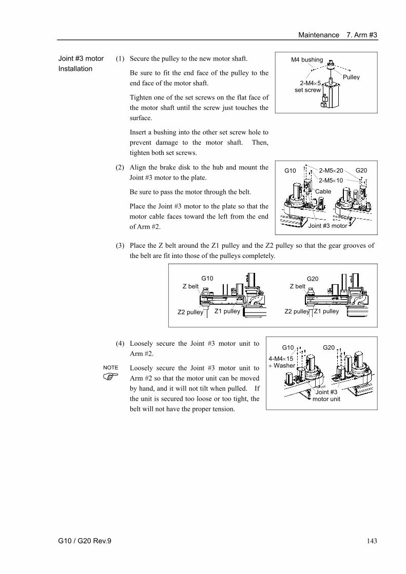
Maintenance 7. Arm #3
G10 / G20 Rev.9 143
M4 bushing
2-M4×5 set screw
Pulley
Joint #3 motor Installation
(1) Secure the pulley to the new motor shaft.
Be sure to fit the end face of the pulley to the end face of the motor shaft.
Tighten one of the set screws on the flat face of the motor shaft until the screw just touches the surface.
Insert a bushing into the other set screw hole to prevent damage to the motor shaft. Then, tighten both set screws.
(2) Align the brake disk to the hub and mount the Joint #3 motor to the plate.
Be sure to pass the motor through the belt.
Place the Joint #3 motor to the plate so that the motor cable faces toward the left from the end of Arm #2.
2-M5×20
Joint #3 motor
2-M5×10G10 G20
Cable
Place the Z belt around the Z1 pulley and the Z2 pulley so that the gear grooves of the belt are fit into those of the pulleys completely.
Z belt
Z2 pulley Z1 pulley
G10
Z belt
Z2 pulley Z1 pulley
G20
(3)
4-M4×15 + Washer
Joint #3motor unit
G10 G20 (4) Loosely secure the Joint #3 motor unit to Arm #2.
Loosely secure the Joint #3 motor unit to Arm #2 so that the motor unit can be moved by hand, and it will not tilt when pulled. If the unit is secured too loose or too tight, the belt will not have the proper tension.
NOTE

Maintenance 7. Arm #3
144 G10 / G20 Rev.9
Apply the proper tension to the Z belt, and then secure the Joint #3 motor unit.
To do so, pass a suitable cord or string around the Joint #3 motor unit near its mounting plate. Then, pull the cord using a force gauge or similar tool to apply the specified tension shown in the figure on the right.
Make sure that the brake cables do not touch the pulley.
4-M4×15 + Washer
G10 : Z belt tension = 130 N (13.3 kgf)
Force gauge
Joint #3 motor unit
4-M4×15 + Washer
G20 : Z belt tension = 130 N (13.3 kgf)
Force gauge
Joint #3motor unit
(5)
4-point mounting
4-M4×10
Plate
Battery unit
G10 G20
3-point mounting
Plate
Battery unit
G10 G20
(6) When you use the plate of 4-point mounting, mount the plate.
When you use the plate of 3-point mounting, mount the plate with pressing it to the motor side*.
* G10 series: Joint #4 motor side G20 series: Joint #3 motor side
When mounting the battery unit mounting bolts, be sure to keep the connectors connected to the battery unit. If connectors of the battery unity are disconnected, you need to perform calibration again.
(7) Connect the connectors X231, X31, and X63.
(8) Re-bundle the cables in their original positions with a wire tie removed in step (5).
Do not allow unnecessary strain on the cables.
(9) Install the arm top cover and the arm bottom cover.
For details, refer to Maintenance: 3. Covers.
(10) Perform the calibration of Joint #3.
For details on the calibration method, refer to Maintenance: 14. Calibration.
NOTE

Maintenance 7. Arm #3
G10 / G20 Rev.9 145
7.2 Replacing the Timing Belt
The length and the replacement procedure of the timing belts for G10 series and G20 series are different.
Maintenance parts, Tools and Material
Name Quantity Note
G10 : 744-3GT width 12 mm 1 R13B030209 Maintenance parts
Z belt G20 : 588-3GT width 12 mm 1 R13B030211
Hexagonal wrench (width across flats: 1.5 mm) G10 1 For M3 set screw Hexagonal wrench (width across flats: 3 mm) 1 For M4 screw Hexagonal wrench (width across flats: 4 mm) 1 For M5 screw Nippers 1 For cutting wire tie Force gauge 1 Belt tension 160 N
(16.3 kgf)Suitable cord (Length about 800 mm) 1 For belt tension
Tools
Wiping cloth 1 For wiping grease Material Wire tie 2

Maintenance 7. Arm #3
7.2.1 Replacing the Timing Belt : G10
A brake is mounted on the motor of Joints #3 and #4 to prevent the shaft from moving down due to the weight of the end effector while the power to the Controller is OFF or while the motor is in OFF status (MOTOR OFF).
Note that the brake will not work during the replacement procedure. Move the shaft down to its lower limit before the replacement procedure following the removal steps.
Z belt Removal : G10
(1) Execute the removal steps from (1) to (10) in Maintenance 7.1 Replacing Joint #3 Motor to remove the Joint #3 motor.
Do not remove the brake unit from Arm #2.
4-M4×15 Joint #4 motor unit
(2) Remove the Joint #4 motor unit from Arm #2.
Pull out the U belt from the U1 pulley to remove it.
2-M3×4 set screw
Brake hub (3) Remove the brake hub.
Loosen the two set screws and pull out the brake hub.
4-M4×12
BrakeWave washer
Bearing
Remove the brake.
There is a wave washer between the housing and the bearing. Be careful not to lose it.
The gear for Z axis is a backlash-less gear. Be sure to keep the gear and pinion engage.
(4)
If the gear is out of joint, refer to step (7) in Ball Screw Spline Unit Installation of Maintenance 10.2.1 Replacing the Ball Screw Spline Unit: G10 to engage the gear.
(5) Remove the Z belt.
Remove the bolts securing the spline plate. Hold the spline plate and pull out the Z belt from the shaft upwards.
3-M5×15 Z belt
Spline plate
146 G10 / G20 Rev.9

Maintenance 7. Arm #3
G10 / G20 Rev.9 147
Z belt Installation : G10
(1) Pass a new Z belt through the shaft from above, and then place it under the spline plate.
(2) Pass the belt through Arm #2.
3-M5×15Z belt
Spline plate (3) Loosely secure the spline plate to Arm #2.
After moving the shaft up and down several times, secure the spline plate to Arm #2.
4-M4×12 Brake Wave washer
Bearing
(4) Mount the brake to the Joint #4 intermediate pulley unit.
When mounting the brake, be sure to keep the wave washer from being stuck.
2-M3×4 set screw
Brake hub (5) Secure the brake hub with the two set screws.
2-M5×20
Cable
2-M5×10
(6) Align the brake disk to the hub and mount the Joint #3 motor to the plate.
Be sure to pass the motor through the belt.
Place the Joint #3 motor to the plate so that the motor cable faces toward the left from the end of Arm #2.
Z belt
Z2 pulley Z1 pulley
(7) Place the Z belt around the Z1 pulley and the Z2 pulley so that the gear grooves of the belt are fit into those of the pulleys completely.
4-M4×15+ Washer
Joint #3 motor unit
(8) Loosely secure the Joint #3 motor unit to Arm #2.
Loosely secure the Joint #3 motor unit to Arm #2 so that the motor unit can be moved by hand, and it will not tilt when pulled. If the unit is secured too loose or too tight, the belt will not have the proper tension.
NOTE

Maintenance 7. Arm #3
148 G10 / G20 Rev.9
4-M4×15+ Washer
Joint #4 motor unit
(9) Set the Joint #4 motor unit in Arm #2.
Place the Joint #4 motor unit in Arm #2 so that the motor cable faces toward the left from the end of the arm.
The screws are not secured in this step.
U belt
U2 pulley U1 pulley
(10) Place the U belt around the U1 pulley and the U2 pulley so that the gear grooves of the belt are fit into those of the pulleys completely.
4-M4×15+ Washer
Joint #4 motor unit
(11) Loosely secure the Joint #4 motor unit to Arm #2.
Loosely secure the Joint #4 motor unit to Arm #2 so that the motor unit can be moved by hand, and it will not tilt when pulled. If the unit is secured too loose or too tight, the belt will not have the proper tension.
4-M4×15 + Washer
G10 : Z belt tension = 130 N (13.3 kgf)
Force gauge
Joint #3motor unit
4-M4×15 + Washer
G10 : U belt tension = 160 N (16.3 kgf)
Force gauge
Joint #4 motor unit
(12) Apply the proper tension to the Z belt and U belt, and then secure the Joint #3 motor unit and Joint #4 motor unit.
To do so, pass a suitable cord or string around the motor unit near its mounting plate. Then, pull the cord using a force gauge or similar tool to apply the specified tension shown in the figure on the right.
Make sure that the brake cables do not touch the pulley.
NOTE

Maintenance 7. Arm #3
G10 / G20 Rev.9 149
(13) When you use the plate of 4-point mounting, mount the plate.
When you use the plate of 3-point mounting, mount the plate pressing it to the Joint #4 motor side.
When mounting the battery unit, be sure to keep the connectors connected to the battery unit. If connectors of the battery unity are disconnected, you need to perform calibration again.
4-point mounting 4-M4×10
Plate
Battery unit 3-point mounting
Plate
Battery unit
(14) Re-bundle the cables in their original positions with a wire tie removed in the removal
procedure. Do not allow unnecessary strain on the cables.
(15) Install the arm top cover and the arm bottom cover. For details, refer to Maintenance: 3. Covers.
(16) Perform the calibration of Joint #3. For details, refer to Maintenance: 14. Calibration.

Maintenance 7. Arm #3
7.2.2 Replacing the Timing Belt : G20
A brake is mounted on the motor of Joints #3 and #4 to prevent the shaft from moving down due to the weight of the end effector while the power to the Controller is OFF or while the motor is in OFF status (MOTOR OFF).
Note that the brake will not work during the replacement procedure. Move the shaft down to its lower limit before the replacement procedure following the removal steps.
Z belt Removal : G20
(1) Execute the removal steps from (1) to (10) in Maintenance 7.1 Replacing Joint #3 Motor to remove the Joint #3 motor.
Do not remove the brake unit from Arm #2.
(2) Remove the Z belt.
Remove the bolts securing the spline plate. Hold the spline plate and pull out the Z belt from the shaft upwards.
3-M5×15 Z belt
Spline plate
(1) Pass a new Z belt through the shaft from above, and then place it under the spline plate.
Z belt Installation : G20
(2) Pass the belt through Arm #2.
(3) Loosely secure the spline plate to Arm #2. After moving the shaft up and down several times, secure the spline plate to Arm #2.
(4) Execute steps from (2) to (10) in Maintenance 7.1 Replacing Joint #3.
150 G10 / G20 Rev.9

Maintenance 7. Arm #3
G10 / G20 Rev.9 151
7.3 Replacing the Brake
Maintenance parts, Tools and Material
Name Quantity Note
G10 1 R13B030503 Maintenance parts
Solenoid brake G20 - -
Hexagonal wrench (width across flats: 1.5 mm) 1 For M3 set screw Hexagonal wrench (width across flats: 2.5 mm) 1 For M3 screw Hexagonal wrench (width across flats: 3 mm) 1 For M4 screw Hexagonal wrench (width across flats: 4 mm) 1 For M5 screw Nippers 1 For cutting wire tie
Tools
Suitable cord (Length about 800 mm) 1 For belt tension Material Wire tie 3
A brake is mounted on the motor of Joints #3 and #4 to prevent the shaft from moving down due to the weight of the end effector while the power to the Controller is OFF or while the motor is in OFF status (MOTOR OFF).
Note that the brake will not work during the replacement procedure. Move the shaft down to its lower limit before the replacement procedure following the removal steps.
(1) Execute the removal steps from (1) to (10) in Maintenance 7.1 Replacing Joint #3 Motor to remove the Joint #3 motor.
(2) Remove the brake unit from Arm #2. Brake unit
G20G10
Joint #3 brake Removal
(3) Disconnect the connector.
Connector X32
3-M3×8
Brake
Brake support
(4) Remove the brake from the brake support.
(5) Remove the brake hub from the Z1 pulley. 2-M3×4
Set screw
Brake hub

Maintenance 7. Arm #3
2-M3×4 Set screw
Brake hub
Joint #3 brake Installation
(1) Mount the brake hub to the Z1 pulley.
3-M3×8
Brake
Brake support
(2) Mount the brake support to the brake.
(3) Mount back the Joint #3 brake unit to Arm #2.
The screws are not secured in this step.
(4) Connect the connector.
Connector X32
Brake unit
G20 G10
(5) Execute steps from (2) to (10) in Maintenance 7.1 Replacing Joint #3.
152 G10 / G20 Rev.9

Maintenance 8. Arm #4
8 153
8. Arm #4 ■ Do not insert or pull out the motor connectors while the power to the robot system
is turned ON. Inserting or pulling out the motor connectors with the power ON is extremely hazardous and may result in serious bodily injury as the Manipulator may move abnormally, and also may result in electric shock and/or malfunction of the robot system.
■ To shut off power to the robot system, pull out the power plug from the power source. Be sure to connect the AC power cable to a power receptacle. DO NOT connect it directly to a factory power source.
WARNING
■ Before performing any replacement procedure, turn OFF the Controller and related equipment, and then pull out the power plug from the power source. Performing any replacement procedure with the power ON is extremely hazardous and may result in electric shock and/or malfunction of the robot system.
■ Be careful not to apply excessive shock to the motor shaft when replacing the
motors. The shock may shorten the life cycle of the motors and encoder and/or damage them.
CAUTION ■ Never disassemble the motor and encoder. A disassembled motor and encoder
will cause a positional gap and cannot be used again.
After parts have been replaced (motors, reduction gear units, brakes, timing belts, ball screw spline unit, etc.), the Manipulator cannot operate properly because a mismatch exists between the origin stored in each motor and its corresponding origin stored in the Controller. After replacing the parts, it is necessary to match these origins.
The process of aligning the two origins is called “Calibration”.
Refer to Maintenance: 14. Calibration to perform the calibration.
G10-65*** manipulator of S/N: 1**** or later is different from other models in its form.
For the detail, refer to Setup & Operation 2.6.4 G10-65***: For S/N: 1**** or later. G10 G20
Joint #4 motor U belt
Joint #4 motor (with brake)
U belt
Joint #4 Reduction gear unit
Joint #4 brake
Joint #4 Reduction gear unit (gear)
NOTE

Maintenance 8. Arm #4
154 8
8.1 Replacing Joint #4 Motor The shape and the replacement procedure of the Joint #4 AC servo motor for G10 series and G20 series are different.
Maintenance parts, Tools and Material Name Quantity Note
R13B000612 AC Servo Motor (150W) G10 R13B000618
(For S/N: 1**** or later)R13B000613
Maintenance
parts
AC Servo Motor (150W with brake) G20
1
R13B000625 (For S/N: 1*** or later)
Hexagonal wrench (width across flats: 1.5 mm) G20 1 For M3 set screw Hexagonal wrench (width across flats: 2 mm) 1 For M4 set screw Hexagonal wrench (width across flats: 2.5 mm) G20 1 For M3 screw Hexagonal wrench (width across flats: 3 mm) 1 For M4 screw Nipper 1 For cutting wire tie
G10 1 Belt tension 160 N
(16.3 kgf) Force gauge
G20 1 Belt tension 200 N
(20.4 kgf)
Scale G20 1 Ring mounting height 16.5 mm
Tools
Suitable cord (Length about 800 mm) 1 For belt tension Material Wire tie 1
8.1.1 Replacing the Joint #4 Motor: G10
A brake is mounted on the motor of Joints #3 and #4 to prevent the shaft from moving down due to the weight of the end effector while the power to the Controller is OFF or while the motor is in OFF status (MOTOR OFF).
Note that the brake will not work during the replacement procedure. Move the shaft down to its lower limit before starting the replacement procedure by following the removal steps.
(1) Turn ON the Controller. Joint #4 motor
Removal: G10 (2) Push down the shaft to its lower limit while pressing the brake release button switch.Be sure to keep enough space and prevent the end effector hitting any peripheral equipment.
The brake release button switch is applied to both Joints #3 and #4. When the brakerelease button switch is pressed, the respective brakes of the Joints #3 and #4 arereleased simultaneously.
Be careful of the shaft falling and rotating while the brake release button switch is being pressed because the shaft may be lowered by the weight of an end effector.
(3) Turn OFF the Controller.

Maintenance 8. Arm #4
8 155
(4) Remove the arm top cover and the arm bottom cover.
For details, refer to Maintenance: 3. Covers.
(5) Cut off the wire tie used for binding the motor cables to the Joint #4 motor.
(6) Disconnect the following connectors. Connectors X241, X41 (Hold the claw to remove.) Connector X64
3-point mounting
Plate
Battery unit
(7) When you use the plate of 3-poin mounting, loosen the plate mounting bolt.
Be sure to keep the connectors connected to the battery unit. If connectors of the battery unity are disconnected, you need to perform calibration again.
When you use the plate of 4-point mounting, you do not have to loosen the plate mounting bolt.
4-M4×15 + Washer
Joint #4 motor unit
(8) Remove the Joint #4 motor unit from Arm #2.
Remove the U belt from the U1 pulley. Pull the Joint #4 motor unit upward to remove.
(9) Remove the U1 pulley and the motor plate from
the Joint #4 motor.
There is a brass bushing in one of the set screw holes. Be careful not to lose it.
2-M4×8 set screw
M4 bushing
Motor plate
Joint #4 motor
Pulley
Bearing
2-M4×15
NOTE

Maintenance 8. Arm #4
156 8
2-M4×8 set screw
M4 bushing
Motor plate
Joint #4 motor
Pulley
Bearing
2-M4×15
Joint #4 motor Installation: G10
(1) Mount the U1 pulley and the motor plate to the new Joint #4 motor.
Pull the pulley to the motor side with 50N force to pressurize the bearing while securing the pulley.
Tighten one of the set screws on the flat face of the motor shaft until the screw just touches the surface.
Insert a bushing into the other set screw hole to prevent damage to the motor shaft. Then, tighten both set screws.
(2) Place the Joint #4 motor unit in the arm so that the motor cable faces toward the left from the end of Arm #2.
4-M4×15 + Washer
Joint #4 motor unit
(3) Place the U belt around the U1 pulley and the U2 pulley so that the gear grooves of the belt are fit into those of the pulleys completely.
U belt
U2 pulley U1 pulley
(4) Loosely secure the Joint #4 motor unit to Arm #2.
Loosely secure the Joint #4 motor unit to Arm #2 so that the motor unit can be moved by hand, and it will not tilt when pulled. If the unit is secured too loose or too tight, the belt will not have the proper tension.
4-M4×15 + Washer
G10 : U belt tension = 160 N (16.3 kgf)
Force gauge
Joint #4 motor unit
(5) Apply the proper tension to the U belt, and then secure the Joint #4 motor unit.
To do so, pass a suitable cord or string around the Joint #4 motor unit near its mounting plate. Then, pull the cord using a force gauge or similar tool to apply the specified tension shown in the figure on the right.
Make sure that the brake cables do not touch the pulley.
3-point mounting
Plate
Battery unit
(6) When you use the plate of 3-point mounting, mount the plate with pressing it to the Joint #4 motor.
Be sure to keep the connectors connected to the battery unit. If connectors of the battery unity are disconnected, you need to perform calibration again.
When you use the plate of 4-point mounting, you do not have to mount the plate.
NOTE
NOTE

Maintenance 8. Arm #4
8 157
(7) Connect the connectors X241, X41, and X64.
(8) Re-bundle the cables in their original positions with a wire tie removed in step (5).
Do not allow unnecessary strain on the cables.
(9) Install the arm top cover and the arm bottom cover.
For details, refer to Maintenance: 3. Covers.
(10) Perform the calibration of Joint #4.
For details on the calibration method, refer to Maintenance: 14. Calibration.

Maintenance 8. Arm #4
8.1.2 Replacing the Joint #4 Motor: G20
A brake is mounted on the motor of Joints #3 and #4 to prevent the shaft from moving down due to the weight of the end effector while the power to the Controller is OFF or while the motor is in OFF status (MOTOR OFF).
Note that the brake will not work during the replacement procedure. Move the shaft down to its lower limit before starting the replacement procedure by following the removal steps.
(1) Turn ON the Controller. Joint #4 motor Removal: G20 (2) Push down the shaft to its lower limit while pressing the brake release button switch.
Be sure to keep enough space and prevent the end effector hitting any peripheral equipment.
The brake release button switch is applied to both Joints #3 and #4. When the brake release button switch is pressed, the respective brakes of the Joints #3 and #4 arereleased simultaneously.
Be careful of the shaft falling and rotating while the brake release button switch is being pressed because the shaft may be lowered by the weight of an end effector.
(3) Turn OFF the Controller.
(4) Remove the arm top cover and the arm bottom cover.
For details, refer to Maintenance: 3. Covers.
(5) Cut off the wire tie used for binding the motor cables to the Joint #4 motor.
(6) Disconnect the following connectors. Connectors X241, X41 (Hold the claw to remove.) Connector X64
2-M4×10
Joint #4 motor
Reduction gear unit
M3×10 (Securing the motor shaft)
(7) Remove the Joint #4 motor from the reduction gear unit.
Unscrew the reduction gear unit bolts securing the Joint #4 motor shaft and bolts securing the Joint #4 motor.
(8) Remove the ring from the Joint #4 motor.
There is a brass bushing in the both set screw holes. Be careful not to lose it.
Bushing
Ring
2-M3×8 set screw
158 8

Maintenance 8. Arm #4
8 159
BushingRing
2-M3×8 set screw
16.5 mm
Joint #4 motor Installation: G20
(1) Mount the ring to the Joint #4 motor.
Be sure to fit the end face of the ring 16.5 mm from the end face of the motor shaft.
Tighten one of the set screws on the flat face of the motor shaft until the screw just touches the surface.
Insert a bushing into the other set screw hole to prevent damage to the motor shaft. Then, tighten both set screws.
(2) Secure the Joint #4 motor to the reduction gear unit so that the Joint #4 motor cable faces toward the left from the end of Arm #2.
(3) Secure the motor shaft to the reduction gear unit.
(4) Connect the connectors X241, X41, and X64.
2-M4×10
Joint #4 motor Reduction gear unit
M3×10 (Securing the motor shaft)
(6) Re-bundle the cables in their original positions with a wire tie removed in the removal procedure.
Do not allow unnecessary strain on the cables.
(7) Install the arm top cover and the arm bottom cover.
For details, refer to Maintenance: 3. Covers.
(8) Perform the calibration of Joint #4.
For details on the calibration method, refer to Maintenance: 14. Calibration.

Maintenance 8. Arm #4
160 8
8.2 Replacing the Timing Belt The length and the replacement procedure of the timing belts for G10 series and G20 series are different.
Maintenance parts and Tools
Name Quantity Note U belt (375-3GT width 15 mm) G10 1 R13B030210 Maintenance
parts U belt (789-3GT width 20 mm) G20 1 R13B030212 Hexagonal wrench (width across flats: 1.5 mm) G10 1 For M3 set screw Hexagonal wrench (width across flats: 3 mm) 1 For M4 screw Hexagonal wrench (width across flats: 4 mm) 1 For M5 screw Nippers 1 For cutting wire tie
Force gauge 1 Belt tension:
130N / 160N / 200N (13.3 kgf / 16.3 kgf / 20.4 kgf)
Tools
Suitable cord (Length about 800 mm) 1 For belt tension

Maintenance 8. Arm #4
8 161
8.2.1 Replacing the Timing Belt: G10
A brake is mounted on the motor of Joints #3 and #4 to prevent the shaft from moving down due to the weight of the end effector while the power to the Controller is OFF or while the motor is in OFF status (MOTOR OFF).
Note that the brake will not work during the replacement procedure. Move the shaft down to its lower limit before starting the replacement procedure by following the removal steps from (1) to (3).
(1) Turn ON the Controller. U belt Removal: G10
(2) Push down the shaft to its lower limit while pressing the brake release button switch. Be sure to keep enough space and prevent the end effector hitting any peripheral equipment.
The brake release button switch is applied to both Joints #3 and #4. When the brakerelease button switch is pressed, the respective brakes for Joints #3 and #4 are released simultaneously.
Be careful of the shaft falling and rotating while the brake release button switch is being pressed because the shaft may be lowered by the weight of an end effector.
(3) Turn OFF the Controller.
(4) Remove the arm top cover and the arm bottom cover.
For details, refer to Maintenance: 3. Covers.
4-point mounting 4-M4×10
Plate
Battery unit
3-point mounting
Plate
Battery unit
(5) When you use the plate of 4-point mounting, remove the plate.
When removing the mounting bolt of battery unit, be sure to keep the connectors connected to the battery unit. If connectors of the battery unity are disconnected, you need to perform calibration again.
When you use the plate of 4-point mounting, loosen the plate mounting bolt.
(6) Loosen the Z belt.
Remove the four bolts securing the Joint #3 motor unit and slide the Joint #3 motor unit to the arm end side.
4-M4×15 + Washer
Joint #3 motor unit

Maintenance 8. Arm #4
162 8
4-M4×15 + Washer
Joint #4 motor unit
(7) Remove the Joint #4 motor unit from Arm #2.
Pull out the U belt from the U1 pulley to remove it.
2-M3×4 set screw
Brake hub (8) Remove the brake hub.
Loosen the two set screws and pull out the brake hub.
4-M4×12
Brake Wave washer
Bearing
(9) Remove the brake.
There is a wave washer between the housing and the bearing. Be careful not to lose it.
The gear for Z axis is a backlash-less gear. Be sure to keep the gear and pinion engage.
If the gear is out of joint, refer to step (7) in Ball Screw Spline Unit Installation of Maintenance 10.2.1 Replacing the Ball Screw Spline Unit: G10 to engage the gear.
(10) Remove the Z belt from the Z pulley and remove the U belt.
Remove the bolts securing the spline plate. Hold the spline plate and pull out the Z belt from the Z pulley upwards to remove the U belt.
3-M5×15
U belt
Spline plate

Maintenance 8. Arm #4
8 163
U belt
Spline plate
U belt Installation: G10
(1) Hold the spline plate and place the U belt around the U2 pulley so that the gear grooves of the belt are fit into those of the pulleys completely.
Z belt
Z2 pulley Z1 pulley
(2) Place the Z belt around the Z1 pulley and the Z2 pulley so that the gear grooves of the belt are fit into those of the pulleys completely.
4-M4×15 + Washer
Joint #3 motor unit
(3) Loosely secure the Joint #3 motor unit to Arm #2.
Loosely secure the Joint #3 motor unit to Arm #2 so that the motor unit can be moved by hand, and it will not tilt when pulled. If the unit is secured too loose or too tight, the belt will not have the proper tension.
4-M4×12
Brake Wave washerBearing
(4) Mount the brake to the Joint #4 intermediate pulley unit.
When mounting the brake, be sure to keep the wave washer from being stuck.
2-M3×4
set screwBrake hub (5) Secure the brake hub with the two set screws.
(6) Loosely secure the Joint #4 motor unit to Arm #2.
Loosely secure the Joint #4 motor unit to Arm #2 so that the motor unit can be moved by hand, and it will not tilt when pulled. If the unit is secured too loose or too tight, the belt will not have the proper tension.
4-M4×15 + Washer
Joint #4motor unit
NOTE
NOTE

Maintenance 8. Arm #4
164 8
(7) Apply the proper tension to the Z belt and U belt, and then secure the Joint #3 motor unit and Joint #4 motor unit.
To do so, pass a suitable cord or string around the motor unit near its mounting plate. Then, pull the cord using a force gauge or similar tool to apply the specified tension shown in the figure on the right.
Make sure that the brake cables do not touch the pulley.
4-M4×15 + Washer
G10 : Z belt tension = 130 N (13.3 kgf)
Force gauge
Joint #3 motor unit
4-M4×15 + Washer
G10 : U belt tension = 160 N (16.3 kgf)
Force gauge
Joint #4 motor unit
(8) When you use the plate of 4-point mounting, mount
the plate.
When you use the plate of 3-point mounting, mount the plate with pressing it to the Joint #4 motor.
When mounting the battery unit, be sure to keep the connectors connected to the battery unit. If connectors of the battery unity are disconnected, you need to perform calibration again.
4-point mounting 4-M4×10
Plate
Battery unit
3-point mounting
Plate
Battery unit
(9) Install the arm top cover and the arm bottom cover.
For details, refer to Maintenance: 3. Covers.
(10) Perform the calibration of Joint #3.
For details, refer to Maintenance: 14. Calibration.
NOTE

Maintenance 8. Arm #4
8 165
8.2.2 Replacing the Timing Belt: G20
A brake is mounted on the motor of Joints #3 and #4 to prevent the shaft from moving down due to the weight of the end effector while the power to the Controller is OFF or while the motor is in OFF status (MOTOR OFF).
Note that the brake will not work during the replacement procedure. Move the shaft down to its lower limit before starting the replacement procedure by following the removal steps.
(1) Turn ON the Controller. U belt
Removal: G20 (2) Push down the shaft to its lower limit while pressing the brake release button switch. Be sure to keep enough space and prevent the end effector hitting any peripheral equipment.
The brake release button switch is applied to both Joints #3 and #4. When the brake release button switch is pressed, the respective brakes of the Joints #3 and #4 are released simultaneously.
Be careful of the shaft falling and rotating while the brake release button switch is being pressed because the shaft may be lowered by the weight of an end effector.
(3) Turn OFF the Controller.
(4) Remove the arm top cover and the arm bottom cover.
For details, refer to Maintenance: 3. Covers.
4-point mounting 4-M4×10
Plate
Battery unit
3-point mounting
PlateBattery unit
(5) When you use the plate of 4-mounting plate, remove the plate.
When you use the plate of 3-point mounting, loosen the plate mounting bolts.
Be sure to keep the connectors connected to the battery unit. If connectors of the battery unity are disconnected, you need to perform calibration again.
4-M4×15 + Washer Joint #3 motor unit
(6) Loosen the Z belt.
Loosen four bolts on the Joint #3 motor unit. Slide the Joint #3 motor unit to the end of the arm.

Maintenance 8. Arm #4
166 8
4-M4×15 + Washer
Joint #4 motor unit
(7) Remove the Joint #4 motor unit from Arm #2.
(8) Remove the Z belt from the Z pulley and remove the
U belt.
Remove the bolts securing the spline plate. Hold the spline plate and pull out the Z belt from the Z pulley upwards and remove the U belt.
3-M5×15
U belt
Spline plate

Maintenance 8. Arm #4
8 167
3-M5×15U belt
Spline plate
U belt Installation: G20
(1) Hold the spline plate and place the U belt around the U2 pulley so that the gear grooves of the belt are fit into those of the pulleys completely.
Z belt
Z2 pulley Z1 pulley
(2) Place the Z belt around the Z1 pulley and the Z2 pulley so that the gear grooves of the belt are fit into those of the pulleys completely.
4-M4×15 + Washer
Joint #3 motor unit
(3) Loosely secure the Joint #3 motor unit to Arm #2.
Loosely secure the Joint #3 motor unit to Arm #2 so that the motor unit can be moved by hand, and it will not tilt when pulled. If the unit is secured too loose or too tight, the belt will not have the proper tension.
(4) Set the Joint #4 motor unit in Arm #2.
Place the Joint #4 motor unit in Arm #2 so that the motor cable faces toward the left from the end of Arm #2.
4-M4×15+ washer
Joint #4 Motor unit
(5) Place the U belt around the U1 pulley and the U2 pulley so that the gear grooves of the belt are fit into those of the pulleys completely.
(6) Loosely secure the Joint #4 motor unit to Arm #2.
Loosely secure the Joint #4 motor unit to Arm #2 so that the motor unit can be moved by hand, and it will not tilt when pulled. If the unit is secured too loose or too tight, the belt will not have the proper tension.
U belt
U2 pulley U1 pulley
NOTE
NOTE

Maintenance 8. Arm #4
168 8
(7) Apply the proper tension to the Z belt and U belt, and then secure the Joint #3 motor unit and Joint #4 motor unit.
To do so, pass a suitable cord or string around each motor unit near its mounting plate. Then, pull the cord using a force gauge or similar tool to apply the specified tension shown in the figure on the right.
Make sure that the brake cables do not touch the pulley.
4-M4×15 + Washer
G20 : Z belt tension = 130 N (13.3 kgf)
Force gauge
Joint #3 motor unit
4-M4×15 + Washer
G20 : U belt tension = 200 N (20.4 kgf)
Force gauge
Joint #4 motor unit
How to apply the proper tension to the U belt of G20 There is a bolt on the Z axis plate part to apply tension to the U belt. (Since it is difficult to apply 200N tension on the U belt only by human power.) The procedure to apply tension using the bolt is as follows.
We recommend the Tensometer U series from Gates Unitta for measuring the belttension.
Tensometer setting Weight 5.25 g/m Width 20 mm Span 297.5 mm
G20: U belt tension Bolt + nut for adjustment (M4)
1. Loosen the nut. Be careful about the motor flange. It may break with too much power.
2. Screw the bolt and push in the U axis plate. 3. Use the ultrasonic gauge to apply the
proper tension to the U axis belt. 4. Secure the U axis unit. 5. Place back the bolt to the position.
Secure the nut. 6. Loosen the nut.

Maintenance 8. Arm #4
8 169
(8) When you use the plate of 3-point mounting, mount the
plate.
When you use the plate of 3-point mounting, mount the plate with pressing it to the Joint #3 motor.
When mounting the battery unit, be sure to keep the connectors connected to the battery unit. If connectors of the battery unity are disconnected, you need to perform calibration again.
4-point mounting 4-M4×10
Plate
Battery unit
3-point mounting
Plate Battery unit
(9) Install the arm top cover and the arm bottom cover.
For details, refer to Maintenance: 3. Covers.
(10) Perform the calibration of Joint #3.
For details, refer to Maintenance: 14. Calibration.
NOTE

Maintenance 8. Arm #4
170 8
8.3 Replacing the Brake The brake of Joint #4 for G20 series is built in the motor. Replace the motor to change the brake.
Maintenance parts, Tools and Material
Name Quantity Note
G10 1 R13B030501 Maintenance parts
Solenoid brake G20 - -
Hexagonal wrench (width across flats: 1.5 mm) 1 For M3 set screw Hexagonal wrench (width across flats: 3 mm) 1 For M4 screw Cross-point screwdriver 1 For M2.5 screw Nippers 1 For cutting wire tie Force gauge 1 Belt tension 160N (16.3 kgf)
Tools
Suitable cord (Length about 800 mm) 1 For belt tension Material Wire tie 1
A brake is mounted on the motor of Joints #3 and #4 to prevent the shaft from moving down due to the weight of the end effector while the power to the Controller is OFF or while the motor is in OFF status (MOTOR OFF).
Note that the brake will not work during the replacement procedure. Move the shaft down to its lower limit before the replacement procedure following the removal steps from (1) to (3).
(1) Turn ON the Controller. Joint #4 brake Removal: G10 (2) Push down the shaft to its lower limit while pressing the brake release button switch.
Be sure to keep enough space and prevent the end effector hitting any peripheral equipment.
The brake release button switch is applied to both Joints #3 and #4. When the brake release button switch is pressed, the respective brakes of the Joints #3 and #4 are released simultaneously.
Be careful of the shaft falling and rotating while the brake release button switch is being pressed because the shaft may be lowered by the weight of an end effector.
(3) Turn OFF the Controller.
(4) Remove the arm top cover.
For details, refer to Maintenance: 3.1 Arm Top Cover.
(5) Disconnect the connector X42.
(6) Cut off the wire tie used for binding the brake cables.

Maintenance 8. Arm #4
8 171
3-point mounting
Plate
Battery unit
G10
(7) When you use the plate of 3-point mounting, loosen the plate mounting bolt.
Be sure to keep the connectors connected to the battery unit. If connectors of the battery unity are disconnected, you need to perform calibration again.
When you use the plate of 4-point mounting, you do not have to loosen the plate mounting bolt.
4-M4×15 + Washer
Joint #4 motor unit
(8) Loosen the U belt.
Loosen bolts on the Joint #4 motor unit. Slide the Joint #4 motor unit to the end of the arm.
NOTE
2-M3×4set screw
Brake hub (9) Remove the brake hub.
Loosen the two set screws and pull out the brake hub.
(10) Remove the brake.
2-M2.5×20
Brake

Maintenance 8. Arm #4
172 8
Joint #4 brake Installation: G10
(1) Mount the brake.
2-M2.5×20 Brake
2-M3×4
set screw
Brake hub (2) Secure the brake hub with the two set screws.
(3) Loosely secure the Joint #4 motor unit to Arm #2.
Loosely secure the Joint #4 motor unit to Arm #2 so that the motor unit can be moved by hand, and it will not tilt when pulled. If the unit is secured too loose or too tight, the belt will not have the proper tension.
4-M4×15 + Washer
Joint #4 motor unit
3-point mounting
Plate
Battery unit
G10
(4) When you use the plate of 3-point mounting, mount the plate with pressing it to the Joint #4 motor.
When mounting the battery unit, be sure to keep the connectors connected to the battery unit. If connectors of the battery unity are disconnected, you need to perform calibration again.
When you use the plate of 4-point mounting, you do not have to mount the plate.
NOTE
NOTE
(5) Apply the proper tension to the U belt, and then secure the Joint #4 motor unit.
To do so, pass a suitable cord or string around the Joint #4 motor unit near its mounting plate. Then, pull the cord using a force gauge or similar tool to apply the specified tension shown in the figure on the right.
4-M4×15 + Washer
G10 : U belt tension = 160 N (16 kgf)
Force gauge
Joint #4 motor unit
(6) Connect the connectors X42.
(7) Re-bundle the cables in their original positions with a wire tie removed in step (6).
Do not allow unnecessary strain on the cables.
(8) Install the arm top cover. For details, refer to Maintenance: 3.1 Arm Top Cover.

Maintenance 8. Arm #4
8 173
8.4 Replacing the Reduction Gear Unit
The shape and the replacement procedure of the reduction gear unit for G10 series and G20 series are different.
Maintenance parts and Tools
Name Quantity Note
Reduction Gear Unit G10 1 R13B031601 Maintenance parts Planetary gear reduction G20 1 R13B010015
Hexagonal wrench (width across flats: 2.5 mm) G10 1 For M3 screw Hexagonal wrench (width across flats: 3 mm) 1 For M4 screw Hexagonal wrench (width across flats: 4 mm) 1 For M5 screw Nippers 1 For cutting wire tie Tools
Force gauge 1 Belt tension
130N / 160N / 200N (13.3 kgf / 16.3 kgf / 20.4 kgf)

Maintenance 8. Arm #4
8.4.1 Replacing the Reduction Gear Unit (Gear): G10 A brake is mounted on the motor of Joints #3 and #4 to prevent the shaft from moving down due to the weight of the end effector while the power to the Controller is OFF or while the motor is in OFF status (MOTOR OFF).
Note that the brake will not work during the replacement procedure. Move the shaft down to its lower limit before the replacement procedure following the removal steps.
U axis gear Removal: G10
(1) Refer to the removal steps (1) to (13) in Maintenance: 10.2.1 Replacing the Ball Screw Spline Unit: G10 and remove the U belt.
M4×10
(2) Secure the Z gear.
Before removing the U gear, secure the Z gear with pressure on the Z gear.
(3) Remove the U axis gear.
(4) Remove the bearing.
U axis gear
Bearing
U axis gear Installation: G10
(1) Mount a new bearing.
U axis gear
Bearing
(2) Mount a new U axis gear.
(3) Execute the installation steps (3) to (23) in Maintenance: 10.2.1 Replacing the Ball Screw Spline Unit: G10.
174 8

Maintenance 8. Arm #4
8 175
8.4.2 Replacing the Reduction Gear Unit: G20
A brake is mounted on the motor of Joints #3 and #4 to prevent the shaft from moving down due to the weight of the end effector while the power to the Controller is OFF or while the motor is in OFF status (MOTOR OFF).
Note that the brake will not work during the replacement procedure. Move the shaft down to its lower limit before the replacement procedure following the removal steps.
(1) Refer to the removal steps (1) to (7) in Maintenance: 8.2.2 Replacing the Timing Belt: G20 and remove the Joint #4 motor unit from Arm #2.
2-M4×10
Joint #4 motor
Joint #4 reduction gear unitM3×10: To secure
the motor shaft
(2) Remove the Joint #4 motor from the reduction gear unit.
Unscrew the bolt of reduction gear unit securing the Joint #4 motor shaft and bolt securing the Joint #4 motor.
Joint #4 reduction gear unit
Plate
4-M5×18
(3) Remove the plate.
Joint #4 Reduction gear unit Removal: G20
(4) Remove the U pulley. Joint #4 reduction gear unit
Pulley
6-M4×15

Maintenance 8. Arm #4
Joint #4 reduction gear unit
6-M4×15
Pulley
(1) Mount the U pulley.
Joint #4 reduction gear unit
Plate
4-M5×18
(2) Mount the plate.
Joint #4 Reduction gear unit Installation: G20
(3) Mount the Joint #4 motor to the reduction gear unit.
Secure the blot of the reduction gear unit securing the Joint #4 motor shaft.
(4) Execute the installation steps (4) to (10) in Maintenance: 8.2.2 Replacing the Timing Belt: G20.
2-M4×10
Joint #4 motor
Joint #4 reduction gear unitM3×10: To secure
the motor shaft
176 8

Maintenance 9. Bellows
G10 / G20 Rev.9 177
9. Bellows
NOTE Two bellows make a set as maintenance parts. There is no difference between the upper bellows and lower bellows. A large amount of dust is emitted when replacing the bellows. Take the Manipulator to an outer room such as the room in front of the clean room’s entrance, or take the necessary countermeasures to prevent dust emission before removing the bellows.
Maintenance parts and Tools Name Quantity Note
150 mm R13B030701 Maintenance parts Bellows
390 mm 1
R13B030703 Tools Cross-point screwdriver 1 For clamp band removal
(1) Remove the end effector. Bellows
Removal (2) Remove the wires and tubes from the end effector.
(3) Turn ON the controller. Stop motor excitation. (MOTOR OFF)
(4) Loosen the two clamp bands on each bellows.
(5) Pull the bellows, rubber sheet, and clamp bands out of the shaft.
(The rubber sheet is not used for the upper bellows.)
Bellows Clamp band (small)
Clamp band (medium)without rubber sheet
Clamp band (large)Clamp band (small)

Maintenance 9. Bellows Bellows Installation
(1) To attach the upper bellows, move the shaft to its lower limit. To attach the lower bellows, move the shaft to its upper limit.
To move the shaft up/down, press and hold the brake release button switch. Be sure to keep enough space and prevent the end effector hitting any peripheralequipment.
The brake release button switch is applied to both Joints #3 and #4. When the brakerelease button switch is pressed, the respective brakes of the Joints #3 and #4 arereleased simultaneously.
Be careful of the shaft falling and rotating while the brake release button switch is being pressed because the shaft may be lowered by the weight of an end effector.
(2) Pass the shaft through the bellows from the larger joint.
Upper bellow cover side
Lower bellow cover side
Bellows Rubber sheet Clamp band
(3) Secure the cover side of the bellows.
The bellows has two joints: The larger joint must be attached to the cover side. The smaller joint must be attached to the end face side of the shaft. Be careful not to misplace the clamp bands. The clamp band has three sizes; small, medium, and large.
Attach the mounting part of the bellows until the end touches the cylindrical part of the cover.
Attach the rubber sheet. Be sure to attach the rubber sheet so that no space is made between the bias cut. (No rubber sheet for the upper bellows cover side)
Bias cut
Then, secure them with clamp bands.
(4) Secure the end face side of the bellows to the shaft.
Cover the bearing case (black) on the end face of the shaft with the bellows mounting part.
Attach the rubber sheet. Be sure to attach the rubber sheet so that no space is made between the bias cut.
Bias cut
Then, secure them with clamp bands.
Upper bellow end face
Lower bellow end face
178 G10 / G20 Rev.9

Maintenance 9. Bellows
G10 / G20 Rev.9 179
(5) After completing the attachment of the bellows, move the shaft up/down by handseveral times and rotate Joint #4. Make sure that the bellows can expand andcontract smoothly without any excessive force.
(6) Turn OFF the Controller and peripheral equipment.
(7) Attach the end effector.
(8) Connect the wires and tubes to the end effector.

Maintenance 10. Ball Screw Spline Unit
180 G10 / G20 Rev.9
10. Ball Screw Spline Unit
■ Do not insert or pull out the motor connectors while the power to the robot system is turned ON. Inserting or pulling out the motor connectors with the power ON is extremely hazardous and may result in serious bodily injury as the Manipulator may move abnormally, and also may result in electric shock and/or malfunction of the robot system.
■ To shut off power to the robot system, pull out the power plug from the power source. Be sure to connect the AC power cable to a power receptacle. DO NOT connect it directly to a factory power source.
WARNING
■ Before performing any replacement procedure, turn OFF the Controller and related equipment, and then pull out the power plug from the power source. Performing any replacement procedure with the power ON is extremely hazardous and may result in electric shock and/or malfunction of the robot system. After parts have been replaced (motors, reduction gear units, brakes, timing belts, ball screw spline unit, etc.), the Manipulator cannot operate properly because a mismatch exists between the origin stored in each motor and its corresponding origin stored in the Controller. After replacing the parts, it is necessary to match these origins.
NOTE
The process of aligning the two origins is called “Calibration”.
Refer to Maintenance: 13. Calibration to perform the calibration.
10.1 Greasing the Ball Screw Spline Unit Maintenance parts and Tools
Name Quantity Note
Maintenance
parts For Ball Screw Spline Unit (AFB grease)
Proper quantity R13ZA00330200
Wiping cloth 1 For wiping grease
Tools Cross-point screwdriver 1
For clamp band removal Only for Cleanroom-model and Protected-model
NOTE The brake release button switch is applied to both Joints #3 and #4. When the brake release button switch is pressed, the respective brakes of the Joints #3 and #4 are released simultaneously. Be careful of the shaft falling and rotating while the brake release button switch is being pressed because the shaft may be lowered by the weight of the end effector.

Maintenance 10. Ball Screw Spline Unit
G10 / G20 Rev.9 181
10.1.1 Standard-model (S type)
Cover the surrounding area such as the end effector and peripheral equipment in case the grease drips.
(1) Turn ON the Controller. Stop motor excitation. (MOTOR OFF)
(2) Move the arm to a position where Joint #3 can be moved in full stroke.
(3) Move the shaft to its upper limit manually while pressing the brake release button switch.
(4) Turn OFF the Controller.
(5) Wipe off the old grease from the upper part of the shaft, and then apply new grease to it.
When applying the new grease to the upper part of the shaft, directly fill the grooves on it by hand. Wipe off excess grease from the shaft.
(6) Turn ON the Controller.
Brake release button switch
(7) Move the shaft to its lower limit manually while pressing the brake release button
switch.
(8) Wipe off the old grease from the lower part of the shaft, and then apply new grease to it.
When applying the new grease to the lower part of the shaft, directly fill the grooves on it by hand. Wipe off excess grease from the shaft.
(9) Move the shaft up and down several times while pressing the brake release buttonswitch to smooth out the grease on the shaft. Wipe off excess grease from the shaft.
When wiping off the excess grease from the upper part of shaft, turn OFF theController and remove the arm top cover. For details, refer to Maintenance: 3.1 Arm Top Cover.

Maintenance 10. Ball Screw Spline Unit
10.1.2 Cleanroom-model / Protected-model (C / D with bellows / P type) Cover the surrounding area such as the end effector and peripheral equipment in case the grease drips.
(1) Turn ON the Controller. Stop motor excitation. (MOTOR OFF) Upper Part of the Shaft (2) Move the arm to a position where Joint #3 can be moved in full stroke.
(3)
Move the shaft to its lower limit manually while pressing the brake release button switch.
Brake release button switch
(4) Clamp band
(4) Loosen the clamp band under the bellows, and then lift the bellows.
(5) Move the shaft to its upper limit manually while
pressing the brake release button switch. (6) Shaft
(7) Clamp band
(6) Wipe off the old grease from the upper part of the shaft, and then apply new grease to it.
Directly fill the grooves on the shaft inside the bellows with grease by hand. Wipe off excess grease from the shaft.
182 G10 / G20 Rev.9

Maintenance 10. Ball Screw Spline Unit
G10 / G20 Rev.9 183
Lower Part of the Shaft
(7) Loosen the clamp band on the bellows, and then move the bellows downward.
(8) Move the shaft to its lower limit manually while pressing the brake release button switch.
(9) Wipe off the old grease from the lower part of the shaft, and then apply new grease to it.
Directly fill the grooves on the shaft inside the bellows with grease by hand. Wipe off excess grease from the shaft.
(9) Shaft
(10) Move the shaft up and down several times while pressing the brake release button switch to smooth out the grease on the shaft. Wipe off excess grease from the shaft.
Secure the bellows.
To attach the upper bellows, move the shaft to its lower limit. To attach the lower bellows, move the shaft to its upper limit. To move the shaft up/down, press and hold the brake release button switch.
Attach the mounting part of the bellows until it touches the cylindrical part of eth cover.
Bias cut
(11)
Attach the rubber sheet. Be sure to attach the rubber sheet so that no space is made between the bias cut. (No rubber sheet for the upper bellows cover side)
Then, secure them with clamp bands.

Maintenance 10. Ball Screw Spline Unit
184 G10 / G20 Rev.9
10.2 Replacing the Ball Screw Spline Unit
The replacement procedure of the ball screw spline unit for G10 series and G20 series are different.
Maintenance parts and Tools Name Quantity Note
Ball Screw Spline Unit 1 Each manipulator model (Refer to Maintenance: 14. Maintenance parts)
Maintenance parts
For Ball Screw Spline Unit (AFB grease) Proper
quantity R13ZA00330200
Hexagonal wrench (width across flats: 1.5 mm) G10 1 For M3 set screw Hexagonal wrench (width across flats: 3 mm) 1 For M4 screw Hexagonal wrench (width across flats: 4 mm) 1 For M5 screw Nippers 1 For cutting wire tie
Cross-point screwdriver 1 Only for Cleanroom-model and Protected-model
Force gauge 1
G10 Belt tension: 130N / 160N (13.3 kgf / 16.3 kgf) G20 Belt tension: 130N / 200N (13.3 kgf / 20.4 kgf)
Suitable cord (Length about 1000 mm) 1 For belt tension
Tools
Wiping cloth 1 For wiping grease
10.2.1 Replacing the Ball Screw Spline Unit: G10
A brake is mounted on the motor of Joints #3 and #4 to prevent the shaft from moving down due to the weight of the end effector while the power to the Controller is OFF or while the motor is in OFF status (MOTOR OFF).
NOTE Note that the brake will not work during the replacement procedure. Move the shaft down to its lower limit before starting the replacement procedure by following the removal steps from (1) to (3).
(1) Turn ON the Controller. Ball screw
spline unit Removal : G10
(2) Push down the shaft to its lower limit while pressing the brake release button switch. Be sure to keep enough space and prevent the end effector hitting any peripheral equipment.
The brake release button switch is applied to both Joints #3 and #4. When the brakerelease button switch is pressed, the respective brakes of the Joints #3 and #4 are released simultaneously.
Be careful of the shaft falling and rotating while the brake release button switch is being pressed because the shaft may be lowered by the weight of an end effector.
(3) Turn OFF the Controller.

Maintenance 10. Ball Screw Spline Unit
G10 / G20 Rev.9 185
(4) Detach the wires/tubes from the end effector, and remove the end effector.
(5) This step is only for Cleanroom-model and Protected-model (C / D with bellows option / P).
Remove the bellows. For details, refer to Maintenance: 9. Bellows.
(6) Remove the arm top cover and arm bottom cover.
For details, refer to Maintenance: 3. Covers.
(7) Cut off the wire tie banding motor cables to the Joint #3 motor and Joint #4 motor.
4-point mounting 4-M4×10
Plate
Battery unit
3-point mounting
Plate
Battery unit
(8) When you use the plate of 4-point mounting, remove the plate.
When you use the plate of 3-point mounting, loosen the plate mounting bolt.
When removing the battery unit mounting bolts, be sure to keep the connectors connected to the battery unit. If connectors of the battery unity are disconnected, you need to perform calibration again.
NOTE
4-M4×15
+ Washer Joint #3 motor unit
(9) Loosen the Z belt.
Loosen four bolts on the Joint #3 motor unit. Slide the Joint #3 motor unit to the end of the arm.
4-M4×15 + Washer
Joint #4 motor unit
(10) Remove the Joint #4 motor unit from Arm #2.
Unscrew the bolts securing the Joint #4 motor unit to the motor plate. Remove the U belt from the U1 pulley. Pull the Joint #4 motor unit upward to remove.
2-M3×4set screw
Brake hub (11) Remove the brake hub.
Loosen the two set screws and pull out the brake hub.

Maintenance 10. Ball Screw Spline Unit
186 G10 / G20 Rev.9
4-M4×12Brake
Wave washerBearing
(12) Remove the brake.
There is a wave washer between the housing and the bearing. Be careful not to lose it.
3-M5×15
U belt
(13) Remove the U belt.
Intermediate pulley
Bearing Shaft
(14) Remove the Joint #4 intermediate pulley.
Remove the shaft from the bearing and remove the intermediate pulley from the lower side of Arm #2.
(15) Remove the nut mounting screws of the ball screw
spline shaft on the lower part of Arm #2.
(16) Pull out the ball screw spline unit from Arm #2.
4-M5×15

Maintenance 10. Ball Screw Spline Unit
G10 / G20 Rev.9 187
(1) Pass the Z belt through the shaft and mount the ball screw spline unit to Arm #2. Ball screw
spline unit Installation : G10
(2) Secure the nut mounting screws of the ball screw spline shaft on lower side of Arm #2.
Be sure to keep the timing belt from being stuck between the nut and Arm #2.
4-M5×15 Mount the Joint #4 intermediate pulley.
Place the M4 bolt position of the Z axis gear to the end of the arm.
Insert the intermediate pulley from the lower side of Arm #2 and engage the gear.
(3)
M4×10
Intermediate pulley
BearingShaft
(4) Remove the bolt of the Z gear.
The gear for Z axis is a backlash-less gear consists of two gears.
The gear and pinion is pressurized. Be sure to keep the gear and pinion engage.
If the gear is out of joint
M4×10
Slotted hole
Assist gear
Main gear
Slotted hole
Tap
Slotted hole
1. Rotate the main gear and the assist gear in the opposite direction and shift one tooth of the gear. (The pin pushes the spring and generates pressure.)
2. Use the tap to mount the M4 bolt.
3. Make sure that the pin position of the main gear is near the center of the slotted hole.
3-M5×15
U belt
(5) Hold the spline plate and place the U belt to the U2 pulley.

Maintenance 10. Ball Screw Spline Unit
188 G10 / G20 Rev.9
Z belt
Z2 pulley Z1 pulley
(6) Set the Z belt around the Z1 pulley and Z2 pulley so that the gear grooves of the belt are fit into those of the pulleys completely.
3-M5×15
Spline plate
(7) Loosely secure the spline plate to Arm #2.
After moving the shaft up and down several times, secure the spline plate to Arm #2.
4-M4×12
Brake Wave washerBearing
(8) Mount the brake to the Joint #4 intermediate pulley unit.
When mounting the brake, be sure to keep the wave washer from being stuck.
2-M3×4set screw
Brake hub (9) Secure the brake hub with the two set screws.
4-M4×15 + Washer
Joint #3 motor unit
(10) Loosely secure the Joint #3 motor unit to Arm #2.
Loosely secure the Joint #3 motor unit to Arm #2 so that the motor unit can be moved by hand, and it will not tilt when pulled. If the unit is secured too loose or too tight, the belt will not have the proper tension.
NOTE
4-M4×15 + Washer
Joint #4 motor unit
(11) Set the Joint #4 motor unit in Arm #2.
Place the Joint #4 motor unit in Arm #2 so that the motor cable faces toward the left from the end of the arm.
The screws are not secured in this step.

Maintenance 10. Ball Screw Spline Unit
G10 / G20 Rev.9 189
U belt
U2 pulley U1 pulley
(12) Place the U belt around the U1 pulley and the U2 pulley so that the gear grooves of the belt are fit into those of the pulleys completely.
4-M4×15 + Washer
Joint #4 motor unit
(13) Loosely secure the Joint #4 motor unit to Arm #2.
Loosely secure the Joint #4 motor unit to Arm #2 so that the motor unit can be moved by hand, and it will not tilt when pulled. If the unit is secured too loose or too tight, the belt will not have the proper tension.
Apply the proper tension to the Z belt and U belt, and then secure the Joint #3 motor unit and Joint #4 motor unit.
To do so, pass a suitable cord or string around the motor unit near its mounting plate. Then, pull the cord using a force gauge or similar tool to apply the specified tension shown in the figure on the right.
Make sure that the brake cables do not touch the pulley.
(14)
NOTE
4-M4×15 + Washer
G10 : Z belt tension = 130 N (13.3 kgf)
Force gauge
Joint #3 motor unit
4-M4×15 + Washer
G10 : U belt tension = 160 N (16.3 kgf)
Force gauge
Joint #4 motor unit
(15) When you use the plate of 4-point mounting, mount
the plate without pressing it to the Joint #4 motor.
When you use the plate of 3-point mounting, mount the plate with pressing it to the motor.
When mounting the battery unit, be sure to keep the connectors connected to the battery unit. If connectors of the battery unity are disconnected, you need to perform calibration again.
4-point mounting 4-M4×10
Plate
Battery unit
3-point mounting
Plate Battery unit
G10
(16) Re-bundle the cables in their original positions with a wire tie removed in the removal procedure. Do not allow unnecessary strain on the cables.
NOTE

Maintenance 10. Ball Screw Spline Unit
190 G10 / G20 Rev.9
(17) If the position of the lower limit mechanical stop was changed for area limit, secure itto the proper position.
(18) Grease the shaft. For details, refer to Maintenance: 10.1. Greasing the Ball Screw Spline Unit.
(19) Install the arm top cover and arm bottom cover. For details, refer to Maintenance: 3. Covers.
(20) Turn OFF the Controller and peripheral equipment.
(21) Install the end effector, and connect wires and tubes to the end effector.
(22) This step is only for Cleanroom-model and Protected-model (C / D with bellows option / P).
Install the bellows. For details, refer to Maintenance: 9. Bellows.
(23) Perform the calibration of Joints #3 and #4.
For details, refer to Maintenance: 14. Calibration.

Maintenance 10. Ball Screw Spline Unit
G10 / G20 Rev.9 191
10.2.2 Replacing the Ball Screw Spline Unit: G20
A brake is mounted on the motor of Joints #3 and #4 to prevent the shaft from moving down due to the weight of the end effector while the power to the Controller is OFF or while the motor is in OFF status (MOTOR OFF).
Note that the brake will not work during the replacement procedure. Move the shaft down to its lower limit before starting the replacement procedure by following the removal steps from (1) to (3).
(1) Turn ON the Controller. Ball screw spline unit Removal : G20
(2) Push down the shaft to its lower limit while pressing the brake release button switch. Be sure to keep enough space and prevent the end effector hitting any peripheral equipment.
The brake release button switch is applied to both Joints #3 and #4. When the brake release button switch is pressed, the respective brakes of the Joints #3 and #4 are released simultaneously.
Be careful of the shaft falling and rotating while the brake release button switch is being pressed because the shaft may be lowered by the weight of an end effector.
(3) Turn OFF the Controller.
(4) Detach the wires/tubes from the end effector, and remove the end effector.
(5) This step is only for Cleanroom-model and Protected-model (C / D with bellows option / P).
Remove the bellows. For details, refer to Maintenance: 9. Bellows.
(6) Remove the arm top cover and the bottom cover.
For details, refer to Maintenance: 3. Covers.
(7) Cut off the wire tie banding motor cables to the Joint #3 motor and Joint #4 motor.
4-point mounting 4-M4×10
Plate
Battery unit
3-point mounting
yPlate
Batter unit
(8) When you use the plate of 4-point mounting, remove the plate.
When removing the battery unit mounting bolts, be sure to keep the connectors connected to the battery unit. If connectors of the battery unity are disconnected, you need to perform calibration again.
When you use the plate of 3 mounting, loosen the plate mounting bolts.

Maintenance 10. Ball Screw Spline Unit
192 G10 / G20 Rev.9
4-M4×15 + Washer
Joint #3 motor unit
(9) Loosen the Z belt.
Loosen four bolts on the Joint #3 motor unit. Slide the Joint #3 motor unit to the end of the arm.
4-M4×15 + Washer
Joint #4 motor unit
(10) Loosen the U belt.
Loosen the bolts mounting the Joint #4 motor unit on the motor plate. Slide the Joint #4 motor unit to the end of the arm.
3-M5×15 + Washer
(11) Remove the nut mounting screws of the ball screw spline shaft on the upper part of Arm #2.
4-M5×15 + Washer
(12) Remove the nut mounting screws of the ball screw spline shaft on the lower part of Arm #2.
(13) Pull out the ball screw spline unit from Arm #2. Ball screw
spline unit

Maintenance 10. Ball Screw Spline Unit
G10 / G20 Rev.9 193
Ball screw
spline unit
Ball screw spline unit Installation : G20
(1) Pass the Z belt through the shaft and mount the ball screw spline unit to Arm #2.
4-M5×15+ Washer
(2) Secure the nut mounting screws of the ball screw spline shaft on lower side of Arm #2.
Be sure to keep the timing belt from being stuck between the nut and Arm #2.
3-M5×15 + Washer
(3) Loosely secure the spline plate to Arm #2.
After moving the shaft up and down several times, secure the spline plate to Arm #2.
Z belt
Z2 pulley Z1 pulley
(4) Set the Z belt around the Z1 pulley and Z2 pulley so that the gear grooves of the belt are fit into those of the pulleys completely.
Joint #3 motor unit
(5) Loosely secure the Joint #3 motor unit to Arm #2.
Loosely secure the Joint #3 motor unit to Arm #2 so that the motor unit can be moved by hand, and it will not tilt when pulled. If the unit is secured too loose or too tight, the belt will not have the proper tension.
(6) Place the U belt around the U1 pulley and the U2
pulley so that the gear grooves of the belt are fit into those of the pulleys completely.
U belt
U2 pulley U1 pulley
(7) Loosely secure the Joint #3 motor unit to Arm #2.
Loosely secure the Joint #3 motor unit to Arm #2 so that the motor unit can be moved by hand, and it will not tilt when pulled. If the unit is secured too loose or too tight, the belt will not have the proper tension.
NOTE
4-M4×15 + Washer
Joint #4 motor unitNOTE

Maintenance 10. Ball Screw Spline Unit
194 G10 / G20 Rev.9
4-M4×15 + Washer
G20 : Z belt tension = 130 N (13.3 kgf)
Force gauge
Joint #3 motor unit
G20 : U belt tension = 200 N (20.4 kgf)
4-M4×15 + Washer
Force gauge
Joint #4 motor unit
(8) Apply the proper tension to the Z belt and U belt, and then secure the Joint #3 motor unit and Joint #4 motor unit.
To do so, pass a suitable cord or string around each motor unit near its mounting plate. Then, pull the cord using a force gauge or similar tool to apply the specified tension shown in the figure on the right.
Make sure that the brake cables do not touch the pulley.
4-point mounting 4-M4×10
Plate
Battery unit 3-point mounting
Plate Battery unit
(9) When you use the plate of 4-point mounting, mount the plate without pressing it to the motor.
When you use the plate of 3-point mounting, mount the plate with pressing it to the motor.
When mounting the battery unit, be sure to keep the connectors connected to the battery unit.
If connectors of the battery unity are disconnected, you need to perform calibration again.
(10) Re-bundle the cables in their original positions with a wire tie removed in the removal
procedure.
Do not allow unnecessary strain on the cables.
(11) If the position of the lower limit mechanical stop was changed for area limit, secure it to the proper position.
(12) Grease the shaft.
For details, refer to Maintenance: 10.1. Greasing the Ball Screw Spline Unit.
(13) Install the arm top cover and arm bottom cover.
For details, refer to Maintenance: 3. Covers.
(14) Turn OFF the Controller and peripheral equipment.
(15) Install the end effector, and connect wires and tubes to the end effector.
NOTE

Maintenance 10. Ball Screw Spline Unit
G10 / G20 Rev.9 195
(16) This step is only for Cleanroom-model and Protected-model (C / D with bellows option / P).
Install the bellows.
For details, refer to Maintenance: 9. Bellows.
(17) Perform the calibration of Joints #3 and #4.
For details, refer to Maintenance: 14. Calibration.

Maintenance 11. Lithium Battery
196 G10 / G20 Rev.9
11. Lithium Battery
■ Do not insert or pull out the motor connectors while the power to the robot system is turned ON. Inserting or pulling out the motor connectors with the power ON is extremely hazardous and may result in serious bodily injury as the Manipulator may move abnormally, and also may result in electric shock and/or malfunction of the robot system.
■ To shut off power to the robot system, pull out the power plug from the power source. Be sure to connect the AC power cable to a power receptacle. DO NOT connect it directly to a factory power source.
WARNING
■ Before performing any replacement procedure, turn OFF the Controller and related equipment, and then pull out the power plug from the power source. Performing any replacement procedure with the power ON is extremely hazardous and may result in electric shock and/or malfunction of the robot system.
■ Use meticulous care when handling the lithium battery. Improper handling of
the lithium battery as mentioned below is extremely hazardous, may result in heat generation, leakage, explosion, or inflammation, and may cause serious safety problems.
<Improper Handling> ・Battery Charge
・Disassembly ・Incorrect Installation ・Exposing to Fire ・Forced Discharge
・Deformation by Pressure ・Short-circuit (Polarity; Positive/Negative) ・Heating (85°C or more) ・Soldering the terminal of the lithium battery directly
CAUTION
■ When disposing of the battery, consult with the professional disposal services or comply with the local regulation. Spent battery or not, make sure the battery terminal is insulated. If the terminal contacts with the other metals, it may short and result in heat generation, leakage, explosion, or inflammation.
When the lithium battery power is low, an error will occur to warn the user about the low battery status when the Controller is turned ON (when software is started up). When the error occurs, the position data in motors will be lost and all joints need to be completely calibrated again. The life span of the lithium battery is 3 years. Even if the Manipulator is constantly connected to power, the lithium battery needs to be replaced every 3 years. If the error of the Power-low warning is not occurred, the calibration of the all joints is not necessary. However, when the position is out of place after the battery replacement, perform the calibration. Be sure to use the specified lithium battery and the battery board. (Refer to Maintenance 15. Maintenance Parts List.) Be sure to set the correct polar when installing the battery.

Maintenance 11. Lithium Battery
G10 / G20 Rev.9 197
Maintenance parts, Tools and Material
Name Quantity Note
Battery unit (Lithium battery) 1 R13ZA00600300 Maintenance parts Battery board 1 R13B041202
Nippers 1 For cutting wire tie Tools Hexagonal wrench (width across flats: 3 mm)
1 For M4 screw (For Replace Battery board)
Material Wire tie 2
11.1 Replacing the Battery Unit (Lithium Battery)
(1) Turn OFF the Controller. Battery unit (lithium battery) Removal
(2) Push down the shaft to its lower limit while pressing the brake release button switch. Be sure to keep enough space and prevent the end effector hitting any peripheral equipment. The brake release button switch is applied to both Joints #3 and #4. When the brake release button switch is pressed, the respective brakes of the Joints #3 and #4 are released simultaneously. Be careful of the shaft falling and rotating while the brake release button switch is being pressed because the shaft may be lowered by the weight of an end effector.
(3) Remove the arm top cover. For details, refer to Maintenance: 3.1 Arm Top Cover.
(4) Connect the connector of the new lithium battery to the battery board. User the unused connector of the two connectors X60A, X60B on the upper part of the battery board. Be sure to connect the connector of the new battery before disconnecting the oldbattery. If the current battery is disconnected before connecting the new battery, the robot will lose the home position data and the calibration must be executed again.
Except when the Power-Low warning is appearing.
G10 G20
X60A
Battery board
X60B Wire tie
(5) Cut off the wire tie banding the cables of used lithium battery. (6) Cut off the wire tie banding the lithium battery and
remove the lithium battery.
Lithium battery
Battery board

Maintenance 11. Lithium Battery
(1) Mount the new lithium battery to the battery board.
(2) Refer to the Removal step (4) to mount cables of the lithium battery and the connector from the battery board.
Lithium battery
Battery board
Battery unit (lithium battery) Installation
(3) Mount the arm top cover. For details, refer to Maintenance: 3.1 Arm Top Cover.
(4) Turn ON the Controller.
(5) Check if the Manipulator moves to points (poses) correctly. To do so, select 2 points (poses) or more from the registered points (poses) and movethe Manipulator to the points (poses).
(6) If the Manipulator does not move to the points (poses) correctly, perform the calibration of all joints and axes. For details, refer to Maintenance: 13. Calibration.
198 G10 / G20 Rev.9

Maintenance 11. Lithium Battery
G10 / G20 Rev.9 199
11.2 Replacing the Battery Board
After battery board and parts have been replaced (motors, reduction gear units, brakes, timing belts, ball screw spline unit, etc.), the Manipulator cannot operate properly because a mismatch exists between the origin stored in each motor and its corresponding origin stored in the Controller. After replacing the parts, it is necessary to match these origins.
The process of aligning the two origins is called “Calibration”.
Refer to Maintenance: 13. Calibration to perform the calibration.
(1) Turn OFF the Controller. Battery board Removal (2) Push down the shaft to its lower limit while pressing the brake release button switch.
Be sure to keep enough space and prevent the end effector hitting any peripheral equipment.
The brake release button switch is applied to both Joints #3 and #4. When the brakerelease button switch is pressed, the respective brakes of the Joints #3 and #4 arereleased simultaneously.
Be careful of the shaft falling and rotating while the brake release button switch is being pressed because the shaft may be lowered by the weight of an end effector.
(3) Remove the arm top cover. For details, refer to Maintenance: 3.1 Arm Top Cover.
(4) Cut off the wire tie banding the connector cables.
G10 G20
(5) Disconnect the connectors X61, X62, X63, and X64 connected to the battery board.
G10 G20
Battery board
X61X63 X64 X62
(6) Loosen the screws securing the battery board and remove the battery board.
G10
Batteryboard
2-M4×10
G20
Batteryboard
2-M4×10

Maintenance 11. Lithium Battery
(1) Mount the new battery board and secure it with screws. Battery board Installation
(2) Connect the connectors X61, X62, X63, and X64.
Battery board
X61
X62 X63
X64
(3) Refer to the Removal step (4) to mount the cables of connector with wire tie.
(4) Mount the arm top cover.
For details, refer to Maintenance: 3.1 Arm Top Cover.
(5) Turn ON the Controller.
(6) Perform the calibration of all joints.
For details, refer to Maintenance: 14. Calibration.
200 G10 / G20 Rev.9

Maintenance 12. LED Lamp
G10 / G20 Rev.9 201
12. LED Lamp
■ Do not insert or pull out the motor connectors while the power to the robot system is turned ON. Inserting or pulling out the motor connectors with the power ON is extremely hazardous and may result in serious bodily injury as the Manipulator may move abnormally, and also may result in electric shock and/or malfunction of the robot system.
■ To shut off power to the robot system, pull out the power plug from the power source. Be sure to connect the AC power cable to a power receptacle. DO NOT connect it directly to a factory power source.
WARNING
■ Before performing any replacement procedure, turn OFF the Controller and related equipment, and then pull out the power plug from the power source. Performing any replacement procedure with the power ON is extremely hazardous and may result in electric shock and/or malfunction of the robot system.
Maintenance parts, Tools and Material
Name Quantity Note
Maintenance parts
LED Lamp 1 R13A030000200
Cross-point screwdriver 1 For wire removal Tools
Nippers 1 Material Wire tie 1
LED Lamp Removal
(1) Remove the arm top cover. For details, refer to Maintenance: 3.1 Arm Top Cover.
(2) Disconnect the X1 and X2 terminals from the LED.
(3) Turn the lens counterclockwise to remove it. Then, turn the lens holder counterclockwise to remove it.
(4) Remove the LED from the arm top cover.
G10 G20
X2 terminalX1 terminal端
Lens
Lens holderRing
LED

Maintenance 12. LED Lamp
202 G10 / G20 Rev.9
LED Lamp Installation
(1) Connect the X1 and X2 terminals to the LED.
Each terminal must be connected to its terminal number on the LED.
(2) Put the arm top cover between the ring and lens holder, and then mount the LED onthe arm top cover.
(3) Install the lens to the lens holder.
(4) Install the arm top cover.
For details, refer to Maintenance: 3.1 Arm Top Cover.

Maintenance 13. Radiating Unit
G10 / G20 Rev.9 203
13. Radiating Unit
■ Do not insert or pull out the motor connectors while the power to the robot system is turned ON. Inserting or pulling out the motor connectors with the power ON is extremely hazardous and may result in serious bodily injury as the Manipulator may move abnormally, and also may result in electric shock and/or malfunction of the robot system.
■ To shut off power to the robot system, pull out the power plug from the power source. Be sure to connect the AC power cable to a power receptacle. DO NOT connect it directly to a factory power source.
■ Before performing any replacement procedure, turn OFF the Controller and related equipment, and then pull out the power plug from the power source. Performing any replacement procedure with the power ON is extremely hazardous and may result in electric shock and/or malfunction of the robot system.
WARNING
■ The radiating unit can be very hot after the robot operation. DO NOT touch and wait until it cools down enough to touch for the replacement work. G10-65*** manipulator of S/N: 1**** or later is different from other models in its form. NOTE
For the detail, refer to Setup & Operation 2.6.4 G10-65***: For S/N: 1**** or later.
Maintenance parts and Tools Name Quantity Note
Maintenance parts G10 1 R13B031906
Hexagonal wrench (width across flats: 3 mm) 1 For M4 screws Spanner (width across flats: 20 mm) 1 For mounting pillar Tools
Nippers 1 For cutting wire tie Radiating Unit Removal
(1) Remove the arm top cover.
For details, refer to Maintenance 3. Covers.
(2) Remove two insulation lock ties that secure the Joint #2 motor and plate.
(3) Remove the radiating sheet from to the plate.
G10-65*** (4) Remove the mounting bolt located in the radiating unit side of heat sink (Hexagon socket head cap bolt (fully threaded)).
The radiating unit side is the right side from the arm forefront.
(5) Pull out the radiating unit upward.
To do so, be careful not to pull out the plate too from the pipe.
NOTE
NOTE

Maintenance 13. Radiating Unit
204 G10 / G20 Rev.9
(1) Insert the radiating unit to the arm from above.
(2) Apply the radiating sheet to the plate.
Make sure the gray color side of radiating sheet faces to the plate.
To do so, put the plate as upper side as possible.
Radiating Unit Installation
(3) Press the plate to the Joint #2 motor and secure the plate and motor using the insulation lock ties in two points (up/down) of the plate.
Be careful not to catch the motor cable.
(4) Secure the heat sink mounting bolt with the pillar.
Hold the pillar with the spanners to avoid it from rotating.
(5) Mount the arm top cover.
For details, refer to Maintenance 3. Covers.
During the installation, be sure to keep the plate attached to the pipe. NOTE

Maintenance 14. Calibration
14. Calibration
14.1 About Calibration After parts have been replaced (motors, reduction gear units, timing belts, etc.), the Manipulator cannot execute the positioning properly because a mismatch exists between the origin stored in each motor and its corresponding origin stored in the Controller. After replacing the parts, it is necessary to match these origins.
The process of aligning the two origins is called “Calibration”. Note that calibration is not the same as teaching*.
*: “Teaching” means to teach the Controller coordinate points (including poses) anywhere in the operating area of the Manipulator.
■ To ensure safety, a safeguard must be installed for the robot system.
For details on the safeguard, refer to EPSON RC+ User’s Guide: 2.4 Installation and Design Precautions.
WARNING
■ Before operating the robot system, make sure that no one is inside the safeguarded area. The robot system can be operated in the mode for teaching even when someone is inside the safeguarded area. The motion of the Manipulator is always in restricted (low speeds and low power) status to secure the safety of an operator. However, operating the robot system while someone is inside the safeguarded area is extremely hazardous and may result in serious safety problems in case that the Manipulator moves unexpectedly.
Command Input Calibration procedures include the process to input commands. Select EPSON RC+ menu-[Tools]-[Command Window] to use the command window.
The information above is omitted in the calibration procedure. Jog Motion The process to set the jog motion is included in the [Jog & Teach] page of the Robot Manager. Select EPSON RC+ menu-[Tools]-[Robot Manager] and select the [Jog & Teach] tab to use the [Jog & Teach] page.
The page above is indicated as [Jog & Teach] in the calibration procedure.
In the following calibration procedure, it uses EPSON RC+ 5.0. When the procedure is different for each type of software, see your software type. EPSON
RC+ 5.0 EPSON
RC+ 6.0
G10 / G20 Rev.9 205

Maintenance 14. Calibration
14.2 Calibration Procedure EPSON RC+ has a wizard for calibration.
This section indicates the calibration using the calibration wizard of EPSON RC+.
You can also calibrate with TP1 in TEACH mode. For details, refer to RC170/RC180 option Teach pendant TP1 manual Operation: 2.7 Calibrating Origin : E2 Series / G Series / RS series.
NOTE
EPSON RC+ 5.0
The same calibration procedure is used for each joint. The follow the steps below are calibration using Joint #1. Follow the steps below to calibrate other joints.
When coordinates for the Manipulator working point require calculation, it is important for Joint #2 to be calibrated accurately. Execute the procedure in “Calibration Using Right / Left Arm Orientations” to accurately calibrate Joint #2. For details, refer to Maintenance: 14.3 Accurate Calibration of Joint #2.
When calibrating Joint #4, you must calibrate Joint #3 and #4 at the same time. You cannot calibrate Joint #4 alone because of the structure of the Manipulator.
If the Err9716 or 5016 appears (Defect of the data backup power for the absolute encoder / Battery replacement / Confirmation of the robot inner wiring) after the motor is replaced, refer to Maintenance: 14.4 Calibration Procedure without using Calibration Wizard and execute the step 3. Encoder Initialization. And then, start the calibration wizard.
The reference point (a point to identify the position of the manipulator) needs to be specified for calibration.
(1) Start the calibration wizard.
i. Select EPSON RC+ menu-[Setup]-[Controller] to display the [Controller] dialog.
EPSON RC+ 5.0
ii. Select [Robot]-[Calibration] to display [Robot Calibration].
iii. Select the joint and click the <Calibrate…> button.
i. Select EPSON RC+ 6.0 menu-[Setup]-[System Configuration].
206 G10 / G20 Rev.9
ii. Select the [Robot]-[Robot**]-[Calibration].
Only selected robot can be calibrated.
EPSON RC+ 6.
NOTE
0

Maintenance 14. Calibration
G10 / G20 Rev.9 207
iii. Select the joint and click the <Calibrate…> button.
(2) Confirm the warning message and click the <Yes> button.
(3) Move the joint to calibrate manually to approximate zero position, as shown in the dialog. After moving the joint click the <Next> button.

Maintenance 14. Calibration 0 pulse position of Joint #1:
position aligned with X-axis in Robot coordinate system
0 pulse
0 pulse position of Joint #2: position where Arms #1 and #2 are in a straight line (Regardless of the Joint #1 direction.)
0 pulse
0 pulse position of Joint #3: upper limit position in motion range
Upper limit : 0 pulse
The height of Joint #3 depends on manipulator model.
Standard model
Cleanroom model /
Protected model
with bellows option 0 pulse position of Joint #4:
position where the flat surface (or screw hole 1) on the shaft faces toward the tip of Arm #2
Flat surface
Screw hole 2 Screw hole 1
0 pulse
Screw hole 1 and flat surface are located in the center of the shaft.
Screw hole 1 and 2 are located at right angles to one another.
208 G10 / G20 Rev.9

Maintenance 14. Calibration
G10 / G20 Rev.9 209
(4) Click the <Yes> button to reset the encoder.
(5) Reboot the Controller.
* This window will disappear when the Controller starts up.
(6) Select the reference point to use for calibration, and click the <Next> button.
(7) Click the <Jog…> button to display the [Jog & Teach] dialog.

Maintenance 14. Calibration
210 G10 / G20 Rev.9
(8) Jog the end effector to approximate reference point in the [Jog & Teach] dialog for rough calibration. Then click the <OK> button.
(9) Click the <Next> button.

Maintenance 14. Calibration
G10 / G20 Rev.9 211
(10) The manipulator moves to the reference point. Click the <Execute> button.
(11) Confirm the message and click the <Yes> button.
(12) After the manipulator moves to the reference point, click the <Next> button.

Maintenance 14. Calibration
212 G10 / G20 Rev.9
(13) Jog to the accurate reference position. Click the <Jog> button.
(14) Jog the end effector to approximate reference point in the [Jog & Teach] dialog for rough calibration. Then click the <OK> button.
* Position Joint #2 only and move Joint #3 to around 0 pulse.

Maintenance 14. Calibration
G10 / G20 Rev.9 213
(15) Click the <Next> button.
(16) Execute the procedure in “Calibration Using Right / Left Arm Orientations” to accurately calibrate Joint #2 only. * Go on to the step (19) for the other joints calibration.
i. Move to another point that has different pose (from righty to lefty) using Jump command. Click the <Yes> button.
ii. Jog to the accurate reference position. Click the <Jog> button.

Maintenance 14. Calibration
214 G10 / G20 Rev.9
iii. Jog to the accurate reference position and adjust the position. Click the <OK> button.
iv. Click the <Next> button.

Maintenance 14. Calibration
G10 / G20 Rev.9 215
(17) Calibration is complete. Click the <Finish> button.

Maintenance 14. Calibration
14.3 Accurate Calibration of Joint #2 When coordinates for the Manipulator working point require calculation, it is important for Joint #2 to be calibrated accurately.
NOTE If the accuracy of Joint #2 is not obtained through the steps in the section 14.2 Calibration Procedure, follow the steps below “Calibration Using Right / Left Arm Orientations” to accurately calibrate Joint #2.
The reference point is the center of the ballscrew spline shaft during this calibration.
When there is a misalignment between thecenter of the end effector and the center of the ball screw spline shaft, remove the end effectorand perform the calibration of the shaft.
The center of the shaft
There is a misalignment between the center of the end effector and the center of the shaft.
Make a calibration jig as shown in the rightfigure and attach it on the end of the shaft tomake the center of the shaft clear.
Decide a target point and mark a cross (×) on it so that you can easily verify the center of theshaft after switching the arm pose between rightand left.
Calibration jig at the end of the shaft (Example)
Target point
The center of the shaft
After removing the end effector and performing the calibration, install the end effector and move the Manipulator to the teaching point to verify whether there is a positional gap. Ifthere is a positional gap, fine-tune the installation position of the end effector and teach thepoint again.
Coordinates for the working point requires calculation in the following cases:
· Teaching the working point by entering the coordinate values (MDI teaching)
· Switching the arm orientation between right and left at a given point
· Using the Pallet command
· Executing CP control (such as liner or circular interpolation)
· Using the Local command
· Pose data specified with relative coordinates <Example: P1+X(100) >
· Vision Guide camera calibrations
216 G10 / G20 Rev.9

Maintenance 14. Calibration
G10 / G20 Rev.9 217
Calibration Using Right / Left Arm Orientations (1) Check the point data for calibration
Use a pose (point) you can easily verify the accuracy within the work envelop ofboth right and left arm. Then, check the number of pose (point) you want to use.
(2) Open the Tools menu | Robot Manager | Control Panel and click the MOTOR ON.
(3) Click the Free All to free all joints from servo control. Now, you can move arms byhands.
(4) Move the arms to the position of point data for calibration in rightly arm orientation.
(5) From the current position, teach any point data number unused. This pose (point) is now called P1.
Specify the point number “1” and click the <Teach> button in the [Jog & Teach].
(6) Click the Lock All in the [Control Panel] to lock all joints under servo control.
(7) Switch to the lefty arm orientation. Then, move the arm to the same point.
>Jump P1/L:Z(0) ' Change the arm orientation from righty to lefty Z is the maximum position
* If there is interference on the way from right to lefty, click the Free All in the[Control Panel] and change the arm orientation to lefty by hands. Then, go to the step (6), (7).
(8) The joints are slightly out of position.
Adjust the gap with the −Z in the Jogging group in the [Jog & Teach]. Then, teachanother point data number unused. This pose (point) is now called P2.
Specify point number “P2” and click the <Teach> button in [Jog & Teach].
(9) Input the new Hofs value.
>Hofs Hofs (1), Hofs (2) + (Ppls(P1,2) + Ppls(P2,2)) / 2,Hofs(3), Hofs(4)
(10) From the current lefty arm orientation (the position in the step (8)), teach the point data number used in the step (8). This pose (point) is called P2.
Specify point number “P2” and click the <Teach> button in [Jog & Teach].
(11) Switch to the righty arm orientation. Then, make sure the manipulator move to thecorrect position.
>Jump P2/R ' Change the arm orientation from lefty to righty
* If there is any interference on the way from lefty to righty, click the Free All in the[Control Panel] and change the arm orientation to righty by hands. Then, go tothe step (6), (11).
(12) Move the manipulator to other point data and make sure it moves to the correctposition. Teach some more points if required.
* Delete the two points taught for the Joint #2 calibration.

Maintenance 14. Calibration
218 G10 / G20 Rev.9
14.4 Calibration Procedure without using Calibration Wizard This section indicates the calibration without using the calibration wizard of EPSON RC+. For details of calibration using the calibration wizard, refer to 14.2 Calibration Procedure.
NOTE
When coordinates for the Manipulator working point require calculation, it is important for Joint #2 to be calibrated accurately. Execute the procedure in “Calibration Using Right / Left Arm Orientations” to accurately calibrate Joint #2. For details, refer to Maintenance: 14.3 Accurate Calibration of Joint #2. You cannot calibrate Joint #4 alone because of the structure of the Manipulator. When calibrating Joint #4, you must calibrate Joint #3 and #4 at the same time.
NOTE The reference point (a point to identify the position of the manipulator) needs to be specified for calibration.
Follow steps 1 to 6 described below in order to calibrate the origin.
1. Basic Pose Confirmation
(1)-1 After the part replacement, perform the calibration using the point data currently registered. Confirm the point data number (P*) to reconstruct the correct manipulator position.
* Point data before the parts replacement (motor, reduction gear, belt, etc.) is necessary for the calibration.
2. Part Replacement
(2)-1 Replace parts as dictated by this manual. Be careful not to injure yourself or damage parts during part replacement.
3. Encoder Initialization
(3)-1 Turn ON the Controller when all joints are in the motion range.
(3)-2 Manually move the joint that needs origin alignment to its approximate 0 pulse position.

Maintenance 14. Calibration 0 pulse position of Joint #1:
position aligned with X-axis in Robot coordinate system
0 pulse
0 pulse position of Joint #2: position where Arms #1 and #2 are in a straight line (Regardless of the Joint #1 direction.)
0 pulse
0 pulse position of Joint #3: upper limit position in motion range
Upper limit : 0 pulse
The height of Joint #3 depends on manipulator model.
Standard model
Cleanroom model /
Protected model
with bellows option 0 pulse position of Joint #4:
position where the flat surface (or screw hole 1) on the shaft faces toward the tip of Arm #2
Flat surface
Screw hole 2Screw hole 1
0 pulse
Screw hole 1 and flat surface are located in the center of the shaft.
Screw hole 1 and 2 are located at right angles to one another.
G10 / G20 Rev.9 219

Maintenance 14. Calibration
220 G10 / G20 Rev.9
(3)-3 Connect EPSON RC+ to the Controller.
Select a robot to be calibrated. Input as below in the [Command Window] and execute it. (This example uses “robot 1”.)
> robot 1
(3)-4 Execute the absolute encoder initialization command.
Input one of the following commands to [Command Window] according to the joint being calibrated.
Joint #1: >EncReset 1 Joint #2: >EncReset 2 Joint #3: >EncReset 3 Joint #4: >EncReset 3, 4
(3)-5 Reboot the Controller.
Select EPSON RC+ menu-[Tools]-[Controller] and click the <Reset Controller> button.
* This window will disappear when the Controller starts up.
4. Rough Calibration
(4)-1 Turn ON the motor from EPSON RC+ menu-[Tools]-[Robot Manager]-[Controller Panel].
(4)-2 Click the <Free All> button in the [Control Panel] page to free all joints andmove the arms manually.
(4)-3 Move the Manipulator to the approximate position and orientation.
(4)-4 To perform temporary calibration, input the pulse value of the specified point data. When the specified point data is “P1,” input and perform the followingcommand to [Command Window] according to the joint being calibrated.
> Calpls Ppls(P1,1), Ppls(P1,2), Ppls(P1,3), Ppls(P1,4)
(4)-5 Perform the temporary calibration.
Input and perform one of the following commands to [Command Window] according to the joint being calibrated.
Joint #1: >Calib 1 Joint #2: >Calib 2 Joint #3:: >Calib 3 Joint #4: >Calib 3, 4
EPSON RC+ 6.0

Maintenance 14. Calibration
G10 / G20 Rev.9 221
5. Calibration (Accurate Positioning)
(5)-1 Click the <Lock All> button in [Control Panel] to put all joints back under servo control.
(5)-2 Move the joint to the specified point using a motion command.
For example, when the specified point data is “P1”, click <MOTOR ON> button in [Control Panel] and execute “Jump P1:Z(0)” from [Jog & Teach].
* The joint NOT being calibrated moves to the original position.
(5)-3 Accurately align the joint* being calibrated to the specified point using jog commands.
* You must move Joint #3 and #4 to the position when calibrating Joint #4.
Select the jog mode [Joint] from [Jog & Teach] to execute the jog motion.
(5)-4 Perform the calibration.
Input and perform one of the following commands to [Command Window] according to the joint being calibrated.
Joint #1: >Calib 1 Joint #2: >Calib 2 Joint #3: >Calib 3 Joint #4: >Calib 3, 4
6. Accuracy Testing
(6)-1 Move the Manipulator to another point to confirm that it moves to the same position. If it does not move to the same position, re-calibrate using another point. You must set the point again if reproducibility cannot be assured through calibration.

Maintenance 15. Maintenance Parts List
222 G10 / G20 Rev.9
15. Maintenance Parts List
15.1 Common Parts Part Name Code Note
Reference page
Joint #1 R13B000610 750 W 122
Joint #2 R13B000611 600 W 128
Joint #3 R13B000607 400 W 136
G10 R13B000612 150 W 149, 151 Joint #4
G20 R13B000613 150 W with brake 149, 153
Joint #1 R13B000624 750 W (For S/N: 1**** or later)
122
Joint #2 R13B000623 600 W (For S/N: 1**** or later)
128
Joint #3 R13B000616 400 W (For S/N: 1**** or later)
136
G10 R13B000618 150 W (For S/N: 1**** or later)
149, 151
AC Servo Motor
Joint #4
G20 R13B000625 150 W with brake (For S/N: 1**** or later)
149, 153
Joint #1 R13B010013 HD32-80 124
Joint #2 R13B010014 HD32-50 132
Joint #2 R13B010028 HD32-50 (For G10-65***/G10-85*** S/N: 1**** or later)
132
G10 R13B031601 G10-U 168
Reduction Gear Unit
Joint #4 G20 R13B010015
HPG-14A21 Planetary gear reduction
169
Z axis R13B030503 146 Solenoid Brake
U axis R13B030501 G10 only *1 165
G10 R13B030209 Z : width 12 mm 744-3GT 140, 141 Joint #3
G20 R13B030211 Z : width 12 mm 588-3GT 145
G10 R13B030210 U1 : width 15 mm 375-3GT 155, 156 Timing Belt
Joint #4 G20 R13B030212 U1 : width 20 mm 789-3GT 160
Battery Board R13B041202 With lithium battery Installed in Arm #2
ER17330V (TOSHIBA) 192
Battery Unit R13ZA00600300Spare lithium battery *2
ER17330V (TOSHIBA) 190
*1 Common with G6 series *2 Common with E2C

Maintenance 15. Maintenance Parts List
G10 / G20 Rev.9 223
Part Name Code Note Reference page
O-ring R13B031228 For Motor flange of Joint #1 123
LED Lamp R13A030000200 *3 194
Ball Screw Spline R13ZA00330200 AFB grease (400 g) *3 174
Reduction Gear Unit R13ZA00330100 SK-1A (500 g) *3 86 Grease
Cable R13B030304 Tube of GPL-224 (227 g) 113
Radiating Unit R13B031906
Heat Sink R13B031907
Radiating Sheet R13B031908
(For G10-65*** S/N: 1**** or later)
195
*3 Common with E2 series
Reduction Gear Unit
A reduction gear unit consists of the following three parts (for Joint #1 and Joint #2). When replacing the reduction gear unit, be sure to always replace the waveform generator, flexspline, and circular spline all together as one set.
Waveform generator
This waveform generator consists of an ellipsoidal cam with ball bearings on its outer circumference. The inner ring of bearings is secured to the cam, while the outer ring is capable of flexible deformation through the ball bearings.
Flexspline
A thin, elastic, cup-shaped metal body with gear teeth around the outer circumference of the opening.
Circular spline
A rigid, ring-shaped body with gear teeth on the inner circumference. The circular spline has two more teeth than the flexspline does. Circular spline Flexspline
Waveform generator
The splines are greased. Be sure to keep the grease from being attaching to the clothes.

Maintenance 15. Maintenance Parts List
224 G10 / G20 Rev.9
15.2 Parts by Environment Model (S: Standard-model C: Cleanroom-model D/P: Protected-model)
Part Name Code Note Reference
page
180 mm R13B010208 S/D (without bellows) 420 mm R13B010209
173, 177
150 mm R13B010210 C
390 mm R13B010211 177
150 mm R13B010212
For G10
P/D with bellows option 390 mm R13B010213
177
180 mm R13B010214 S/D (without bellows) 420 mm R13B010215
184
150 mm R13B010216 C
390 mm R13B010217 184
150 mm R13B010218
Ball Screw Spline
For G20
P/D with bellows option 390 mm R13B010219
184
650 mm R13B020033
850 mm R13B020018
1000 mm R13B020019
Inner wiring cable
650 mm R13B020048
850 mm R13B020050
S/C
1000 mm R13B020052
(For S/N: 1**** or later)
106
650 mm R13B020034
850 mm R13B020020
1000 mm R13B020021
Inner wiring cable
650 mm R13B020049
850 mm R13B020051
Cable Unit
P/D
1000 mm R13B020053
(For S/N: 1**** or later)
106
Cable Length 3 m R12B020425
Cable Length 5 m R12B020426 S/C
Cable Length 10 m R12B020427
*1 49
Cable Length 3 m R12B020428
Cable Length 5 m R12B020429
M/C Cable
P/D
Cable Length 10 m R12B020430
*1 49
S/D R13B030410 White painting Arm Cover
C/P R13B030414 Plating 97, 99

Maintenance 15. Maintenance Parts List
G10 / G20 Rev.9 225
Part Name Code Note Reference
page
150 mm R13B030701 *1 Bellows
C/P/D with bellows option 390 mm R13B030703
171
Gasket Unit D/P R13B031231 88-94
Arm #2 Gasket P R13B031232
S/C R13Z702640100 *3 Brake Release Switch P/D R13B060902 *1
174
*1 Common with G6 series
*3 Common with E2 series

Maintenance 15. Maintenance Parts List
226 G10 / G20 Rev.9