Embed Size (px)
Citation preview

UniGear ZS1 DigitalG. Vasconcelos / J.C. Procópio / E. Neves – Medium Voltage SWG, August 2015
Reliability, Security and Economy

© ABB Group
September 14, 2015 | Slide 2
UniGear ZS1 DigitalAdvanced measurement solution
Current sensors Voltage sensors

© ABB Group
September 14, 2015 | Slide 3
UniGear ZS1 DigitalIEC standards for non-conventional ITs: MV Sensors
MV sensors IEC standards
ABB current sensor • IEC 60044-8 (2002)Electronic current transformers
ABB voltage sensor • IEC 60044-7 (1999)Electronic voltage transformers

© ABB Group
September 14, 2015 | Slide 4
UniGear ZS1 DigitalIEC standards for non-conventional ITs: Sensor definition
Primary
sensorPrimary
converter
Transmission
system
Secondary
converter
Power
supply
Power
supply
Relay
ABB MV sensors:
General definition (IEC 60044-8):
SensorRelay
No primary/secondary converter used in ABB MV sensors nowadays
= no active electronic needed inside of the sensor, no additional power supply = pure passive sensors
Signal integration for current sensors done at relay side

© ABB Group
September 14, 2015 | Slide 5
UniGear ZS1 DigitalCurrent sensor based on Rogowski coil principle
IP
US
ABB RogowskiUs=150 mV for 50 Hz
Us=180 mV for 60 Hz
Proved technology which
brings many benefits in
various applications
Output voltage is
proportional to the derivate
of primary current
Output voltage is integrated
by IED
Accuracy up to class 0.5
Complies with IEC 60044-8
dt
tdiMtu
p
s
)()(
© ABB Group
September 14, 2015 | Slide 6
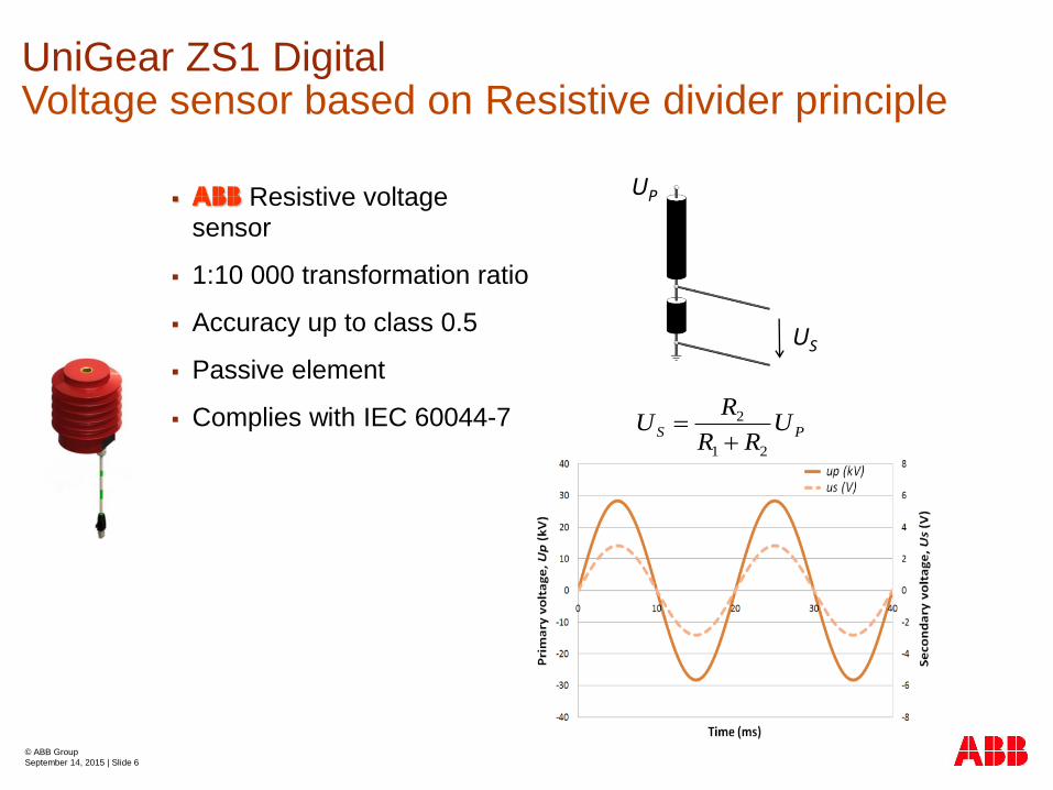
UniGear ZS1 DigitalVoltage sensor based on Resistive divider principle
ABB Resistive voltage sensor
1:10 000 transformation ratio
Accuracy up to class 0.5
Passive element
Complies with IEC 60044-7
US
UP
PS URR
RU
21
2
© ABB Group
September 14, 2015 | Slide 7
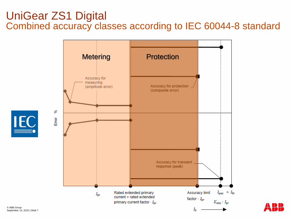
UniGear ZS1 DigitalCombined accuracy classes according to IEC 60044-8 standard
Metering Protection

© ABB Group
September 14, 2015 | Slide 8
UniGear ZS1 DigitalAccurate in the whole operating range (class 0.5/3P)
ε[%]
Continuous voltage measurement
0.02*Upn Upn 1.2*Upn 1.9*Upn
+0.5%
+6%
-6%
-0.5%
Metering accuracy limit class 0.5
Protection accuracy limit class 3P
≈
0.8*Upn
+3%
-3%
≈
Up

© ABB Group
September 14, 2015 | Slide 9
UniGear ZS1 Digital
Sensors are produced with small manufacturing tolerances.
Due to the linear characteristic of sensor, measurement
error caused by manufacturing tolerances can be
compensated by using of correction factors in IEDs.
Correction factors used for current and voltage sensors:
Amplitude correction factors „aI“ and „aU“
4 decimal places
Phase error correction factors „pI“ and „pU“
4 decimal places
expressed in degrees
Improving measurement accuracy: Correction factors

© ABB Group
September 14, 2015 | Slide 10
UniGear ZS1 DigitalLinear characteristic = No saturation
Saturation
level
Primary current
Secondary
output
10A 100A 1000A 10 000A
ABB sensor
Standard CT

© ABB Group
September 14, 2015 | Slide 11
4000 A; 50 kA
Vo
ltag
e
tran
sfo
rmers
Cu
rren
t
tran
sfo
rmers
Sen
so
rs
17.5 kV
Variants
5.500
26.500
2
1
UniGear ZS1 DigitalOnly 3 sensor variants cover all applications

© ABB Group
September 14, 2015 | Slide 12
UniGear ZS1 Digital
CT needs to consume the energy to be able to transfer the
primary current to the secondary current.
The energy consumption is represented by power losses in
time.
The CT active power losses consist of:
power losses in primary winding
hysteresis and eddy-current losses
power losses in secondary winding
power losses in burden
Negligible energy consumption
Zp Zs
ZbZ0

© ABB Group
September 14, 2015 | Slide 13
Typical switchboard was selected where were calculated
2 varints with CTs and one variant with sensors:
A) CTs with secondary rated current 1A
B) CTs with secondary rated current 5A
C) Sensors
The selected switchboard consists of 14 panels:
2 Incoming feeders with CTs 1000/x/x A
8 Outgoing feeders 1 with CTs 200/x/x A
4 Outgoing feeders 2 with CTs 100/x/x A
All CTs have 2 cores:
Protection core class 5P20, 20VA connected to the
IED
Metering core class 0.5Fs5, 5VA connected to the
analog ampere-meter
UniGear ZS1 DigitalNegligible energy consumption

© ABB Group
September 14, 2015 | Slide 14
UniGear ZS1 DigitalEnergy consumption
Feeder CTs Number of
panels
Number of
CTs
Power consumption Energy
consumption in 30
years
Incoming 1000/1/1A 2 6 140 VA 36 698 kWh
Outgoing 1 200/1/1A 8 24 448 VA 117 776 kWh
Outgoing 2 100/1/1A 4 12 102 VA 26 724 kWh
Total - 14 42 690 VA 181 198 kWh
a) CTs with rated secondary current 1A
Feeder CTs Number of
panels
Number of
CTs
Power consumption Energy
consumption in 30
years
Incoming 1000/1/1A 2 6 172 VA 45 244 kWh
Outgoing 1 200/1/1A 8 24 629 VA 165 208 kWh
Outgoing 2 100/1/1A 4 12 179 VA 47 124 kWh
Total - 14 42 980 VA 257 576 kWh
b) CTs with rated secondary current 5A

© ABB Group
September 14, 2015 | Slide 15
Feeder Number of
panels
Number of
Sensors
Power
consumption
Energy
consumption in 30
years
Incoming 2 6 0,0000 VA 0,0000 kWh
Outgoing 1 8 24 0,0000 VA 0,0000 kWh
Outgoing 2 4 12 0,0000 VA 0,0000 kWh
Total 14 42 0,0000 VA 0,0001 kWh
UniGear ZS1 DigitalEnergy consumption
c) Sensors
vs 257.6 MWh (in 5A)

© ABB Group
September 14, 2015 | Slide 16
UniGear ZS1 Digital
Current
sensor
Voltage
sensor
Voltage
transformer
Current
transformer
1piece=24kg 1piece=35kg 1piece=0.5kg 1piece=2kg
3x24 + 3x35=177kg 3x0.5 + 3x2=7.5kg
vs.
Smaller dimensions and easing to handle

© ABB Group
September 14, 2015 | Slide 17
KECA 80 C165KECA 80 C104 KEVA 17.5 B20
UniGear ZS1 DigitalTwo current sensors and one voltage sensor
For e.g. UniGear ZS1 Digital up to 17.5kV, 4000A, 50kA, two current
sensors and one voltage sensor are required only
© ABB Group
September 14, 2015 | Slide 18
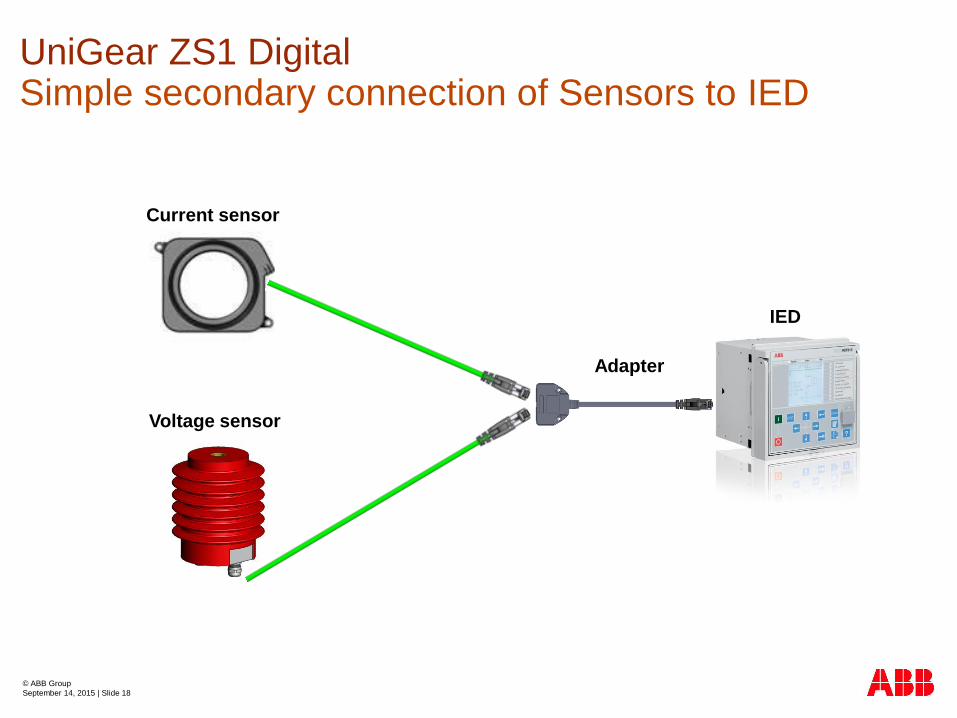
Current sensor
Voltage sensor
IED
Adapter
UniGear ZS1 DigitalSimple secondary connection of Sensors to IED
© ABB Group
September 14, 2015 | Slide 19
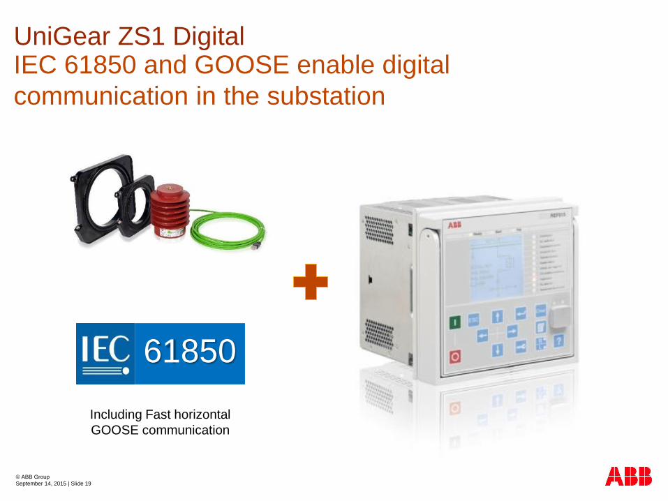
61850
Including Fast horizontal
GOOSE communication
UniGear ZS1 DigitalIEC 61850 and GOOSE enable digital
communication in the substation

© ABB Group
September 14, 2015 | Slide 20
UniGear ZS1 DigitalSecondary testing of IEDs: Conventional ITs
Analogue signal:
• 3 x I (1A; 5A)
• 3 x U (100V; 110V; 220V)
Tester
Classical wire system
Switchgear LV compartment
CTs/VTs
terminals
VTs
MCB
© ABB Group
September 14, 2015 | Slide 21
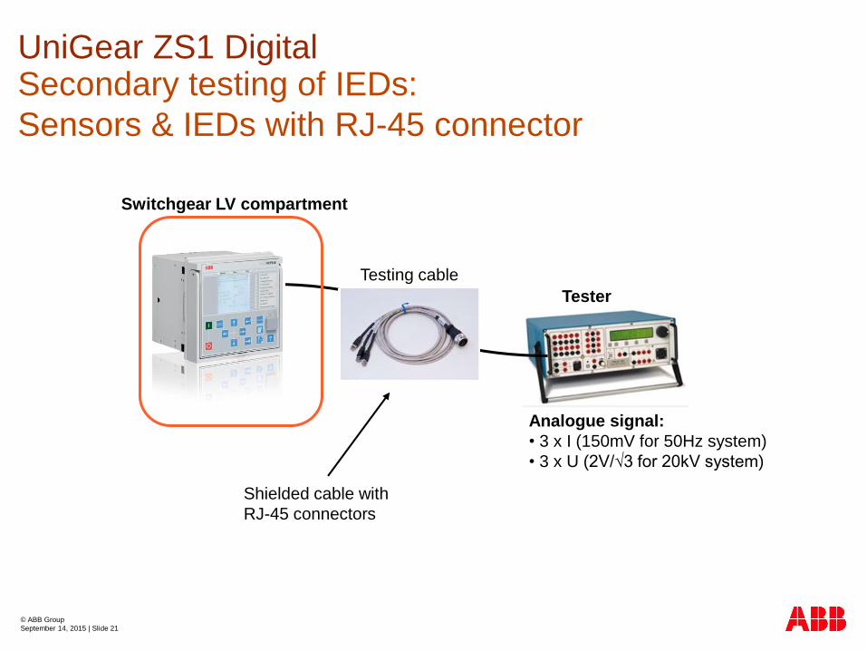
UniGear ZS1 DigitalSecondary testing of IEDs:
Sensors & IEDs with RJ-45 connector
Tester
Testing cable
Shielded cable with
RJ-45 connectors
Analogue signal:
• 3 x I (150mV for 50Hz system)
• 3 x U (2V/√3 for 20kV system)
Switchgear LV compartment
© ABB Group
September 14, 2015 | Slide 22
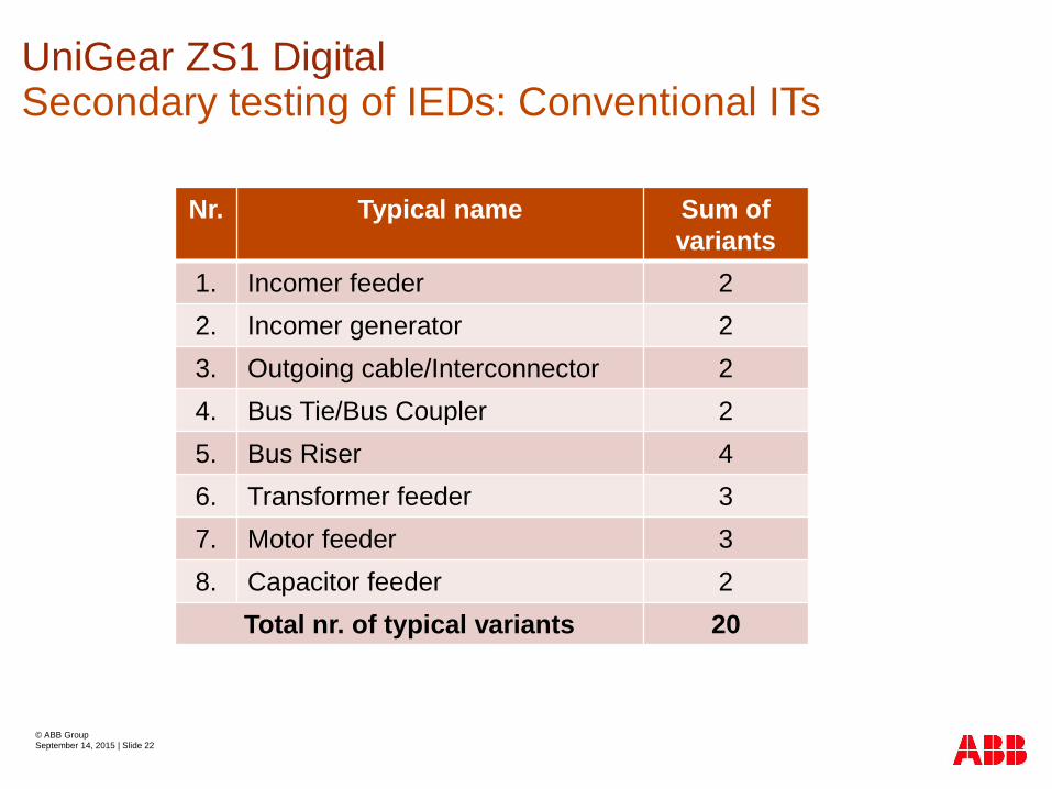
Nr. Typical name Sum of
variants
1. Incomer feeder 2
2. Incomer generator 2
3. Outgoing cable/Interconnector 2
4. Bus Tie/Bus Coupler 2
5. Bus Riser 4
6. Transformer feeder 3
7. Motor feeder 3
8. Capacitor feeder 2
Total nr. of typical variants 20
UniGear ZS1 DigitalSecondary testing of IEDs: Conventional ITs
© ABB Group
September 14, 2015 | Slide 23
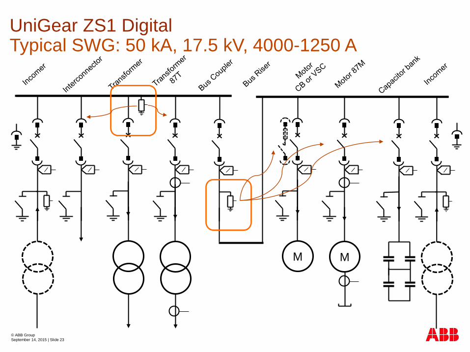
UniGear ZS1 DigitalTypical SWG: 50 kA, 17.5 kV, 4000-1250 A
M M

© ABB Group
September 14, 2015 | Slide 24
UniGear ZS1 DigitalTypical Unity: Incoming Transformer (including 87T)
REF615 std.conf G/L
optional RIO600
(PSM, COM, BIM8,
BOM4, AOM)
RET615 std.conf
A/B/C/D (with I/O)
Voltage
over
IEC 61850-9-2
REF615
Binary inputs – 8x
BI1 - SPARE
BI2 - SPARE
BI3 – STATUS CB OPEN
BI4 – STATUS CB CLOSED
BI5 – CB TRUCK IN TEST
BI6 – CB TRUCK IN SERVICE
BI7 –STATUS ES OPEN
BI8 – STATUS ES CLOSED
Binary outputs – 10x
BO1 – RELEASE FOR CB CLOSING (RL1)
BO2 - COMMAND CB CLOSE (MC)
BO3 - COMMAND CB OPEN/TRIP (MO1)
BO4 - COMMAND CB OPEN/TRIP (MO2) (RESERVED FOR)
BO5 - RELEASE FOR CB TRUCK (RL2) (RESERVED FOR)
BO6 - RELEASE FOR ES (RL3) (RESERVED FOR)
BO7 - SPARE
BO8 - SPARE
BO9 - SPARE
BO10 - SPARE
RET615
Binary inputs – 14x
BI1 – Buchholz Alarm
BI2 – Buchholz Trip
BI3 – Temp. Alarm
BI4 – Temp. Trip
BI5 - BI14 - SPARE
Binary outputs – 13x
BO1 – SPARE
BO2 - SPARE
BO3 - COMMAND CB OPEN/TRIP (MO1)
BO4 - COMMAND CB OPEN/TRIP (MO2) (RESERVED FOR)
BO5 - SPARE
BO6 – BO13 - SPARE
REF615 (main prot. relay) + RET615 (trans. diff. 87T and Restricted EF 87N)
© ABB Group
September 14, 2015 | Slide 25
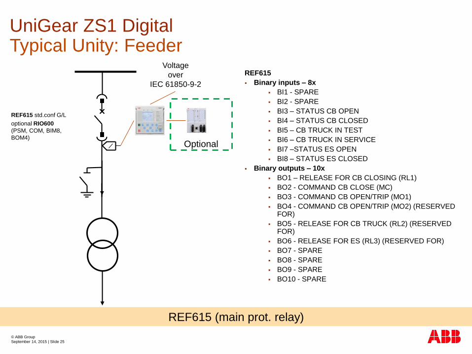
REF615 std.conf G/L
optional RIO600
(PSM, COM, BIM8,
BOM4)
Voltage
over
IEC 61850-9-2
REF615
Binary inputs – 8x
BI1 - SPARE
BI2 - SPARE
BI3 – STATUS CB OPEN
BI4 – STATUS CB CLOSED
BI5 – CB TRUCK IN TEST
BI6 – CB TRUCK IN SERVICE
BI7 –STATUS ES OPEN
BI8 – STATUS ES CLOSED
Binary outputs – 10x
BO1 – RELEASE FOR CB CLOSING (RL1)
BO2 - COMMAND CB CLOSE (MC)
BO3 - COMMAND CB OPEN/TRIP (MO1)
BO4 - COMMAND CB OPEN/TRIP (MO2) (RESERVED FOR)
BO5 - RELEASE FOR CB TRUCK (RL2) (RESERVED FOR)
BO6 - RELEASE FOR ES (RL3) (RESERVED FOR)
BO7 - SPARE
BO8 - SPARE
BO9 - SPARE
BO10 - SPARE
Optional
REF615 (main prot. relay)
UniGear ZS1 DigitalTypical Unity: Feeder

© ABB Group
September 14, 2015 | Slide 26
Keep project time
schedule
Keep cost targets
Flexible to changes
Maximize integration
Comply with specifications and standards
UniGear ZS1 DigitalLess worries in your electrical network

© ABB Group
September 14, 2015 | Slide 27
UniGear ZS1 Digital has 332 panels in orders since 2014, 158 panels already delivered
Slovakia
73 panels
U.A.E.
34 panels
Sweden
11 panelsEstonia
9 panels
Belgium
18 panels
South Africa
13 panels
Czech rep.
88 panels
Georgia
6 panels
Ireland
3 panels
Poland
26 panels
Turkey
51 panels
© ABB Group
September 14, 2015 | Slide 28
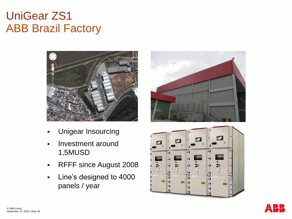
UniGear ZS1ABB Brazil Factory
Unigear Insourcing
Investment around
1,5MUSD
RFFF since August 2008
Line’s designed to 4000
panels / year

© ABB Group
September 14, 2015 | Slide 29
UniGear ZS1Other design concepts
Single Busbar System
Double Level System
Back-to-back System
MCC

© ABB Group
September 14, 2015 | Slide 30
UniGear ZS1Single level / single busbar
E.g.: UniGear ZS1 for
Marine application
W
H
D

© ABB Group
September 14, 2015 | Slide 31
UniGear ZS1Single level / single busbar
Rated voltage
Test voltage (50-60 Hz/1 min)
Impulse withstand voltage
Rated frequency
Rated short-time withstand current
Peak withstand current
Internal arc withstand current
Rated current of the main busbars
Rated circuit-breaker thermal current
Feeders rated current
[kV]
[kV]
[kV]
[Hz]
[kA]
[kA]
[kA]
[A]
[A]
[A]
Up to
Up to
Up to
Up to
Up to
12 (*)
28
75
50-60
50
125
50
4000
4000
630
1250
1600
2000
2500
3150
3600
4000
Rated voltage
Test voltage (50-60 Hz/1 min)
Impulse withstand voltage
Rated frequency
Rated short-time withstand current
Peak withstand current
Internal arc withstand current
Rated current of the main busbars
Rated circuit-breaker thermal current
Feeders rated current
with natural ventilation
Feeders rated current
with forced ventilation
[kV]
[kV]
[kV]
[Hz]
[kA 3s]
[kA]
[kA 1s]
[A]
[A]
[A]
Up to
Up to
Up to
Up to
Up to
12
28
75
50-60
50
125
50
4000
4000
630
1250
1600
2000
2500
3150
3600
4000
17,5
38
95
50-60
50
125
50
4000
4000
630
1250
1600
2000
2500
3150
3600
4000
24
50
125
50-60
31,5
80
31,5
3150
3150
630
1250
1600
2000
2300
2500
3150

© ABB Group
September 14, 2015 | Slide 32
UniGear ZS1MCC: IEC classification
Loss of Service continuity LSC-2A
Partition Metallic - PM
Complete of safety mechanical
interlocks (interlock-controlled
and tool-based accessible
compartments)
Metallic busbar shutter operated
by the apparatus movement
Closed door apparatus racking
Compartments
C
A
B
Contactor and cable compartment
Busbar compartment
Low voltage compartment
D Gas duct
A
C B
D
© ABB Group
September 14, 2015 | Slide 33
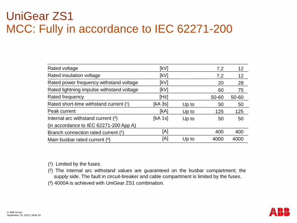
UniGear ZS1MCC: Fully in accordance to IEC 62271-200
Rated voltage
Rated insulation voltage
Rated power frequency withstand voltage
Rated lightning impulse withstand voltage
Rated frequency
Rated short-time withstand current (¹)
Peak current
Internal arc withstand current (²)
(in accordance to IEC 62271-200 App A)
Branch connection rated current (¹)
Main busbar rated current (³)
[kV]
[kV]
[kV]
[kV]
[Hz]
[kA 3s]
[kA]
[kA 1s]
[A]
[A]
Up to
Up to
Up to
Up to
7,2
7,2
20
60
50-60
50
125
50
400
4000
12
12
28
75
50-60
50
125
50
400
4000
(¹) Limited by the fuses.
(²) The internal arc withstand values are guaranteed on the busbar compartment; the
supply side. The fault in circuit-breaker and cable compartment is limited by the fuses.
(³) 4000A is achieved with UniGear ZS1 combination.
© ABB Group
September 14, 2015 | Slide 34
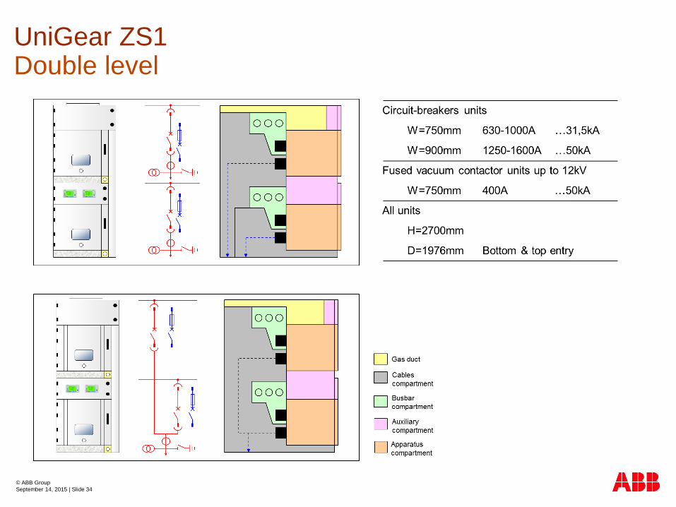
UniGear ZS1Double level

© ABB Group September 14, 2015 | Slide 35
R
L
R
L
R
L
R
L
R
L
R
L
R
L
R
L
R
L
R
L
R
L
R
L
R
L
R
L
R
L
R
L
Outgoing
feeders
with circuit
breakers
Outgoing
feeders with
contactors
Metering unit
Outgoing
feeder
Incoming
feeder
Bus tie Bus riser Incoming
feeder
Metering unit
Outgoing
feeder
Outgoing
feeders with
contactors
Outgoing
feeders
with circuit
breakers
UniGear ZS1Double level: Configuration with single level units

© ABB Group
September 14, 2015 | Slide 36
UniGear ZS1Back-to-back
Double busbar system in back to back arrangement
Circuit-breakers between busbars
Same features as single busbar system

© ABB Group
September 14, 2015 | Slide 37
Answer
Question
Question and answerUniGear ZS1 Digital