Embed Size (px)
Citation preview

G. TannenbaumElectronic Service DataP.O. Box 386/Ambler PA 19002
Phone 215 657 0106 Fax 215 657 0520Web Page www.agtannenbaum.com
EA TH KIT
MODEL AG-AUDIO GENERATOR


G AG YO
-III!-~Audio Generator
.. Model AG-
THE HEATH COMPANYBENTON HARBOR, MICH.
PRICE $1.
- n
~--- -- - ---- __
d__--__- --
~------ -----

,"""""""""""""""""""""" U
"""""""""""""""" "'" ""'"
I NFORMA lrON FOR KIT
,,',,""""""""""""""""""""""""""""""""""""""""""
Resistors are identified by a color code used in several bands around the resistors. There are twogeneral types of resistors. One, the uninsulated type, has the connecting wires bound around the ends.The other, the insulated type, has the wire connected internally and coming out the ends. The resist-ance code uses three bands or colors, while a fourth, usually silver or gold, indicates the tolerance. Thecolors are arranged so that the first two indicate the first two figures of the resistance, whilethe third indicates the number of digits (zeros or multiplier) which follow the first two figuresOn w1insulated resistors, the body is the first figure, the end color the second figure, and thedot the number of digits. On insulated resistors, the band nearest the end is the first figurethe next band is the second figure and the third band the number of digits.
WATTAGE. Resistors are rated as to wattage (power dissipation) according to size.The chart shows approximate sizes which vary with manufacturers. To determine wat-tage size necessary multiply current through resistor in , amperes by voltage drop acrossresistors in volts. Example - A plate loading resistor for a tube drawing 10 milli-amperes (.01 Amperes) has a voltage on one side of 300 volts and on the other side200 volts, giving a drop of 100 volts. Therefore 100 volts X .01A. = 1 Watt.
A higher wattage resistor can always be substituted for smaller size.
-fDI=1m
~.~,
V2.W
1 W.
2W.
WATTAG E SIZES
Un insulated Body Color End Color Dot Color UNINSUL-RTED Examples INSULATED TYPEInsulated First Ring Second Ring Third Ring TYPE; Forth. Band
-Fo,.. To/etanceColor lrKt Figure "eeond Figure Number of DigitsBlack NoneBrownRedOrange 000Yellow 000Green 00. 000Blue 000. 000Violet 000. 000 BROWN RED ORANGE BROWN RED ORANCJEGrey 00. 000. 000 000 000White 000. 000, 000
Some Popular Si zes ResistorsRESISTANCE IN
2501500
30, 000220 0001 Megohm
OHMS BODY OR FIRSTGreenRedBrownOrangeRedBrown
BANI) DOT OR THIRDBlackBrownHedOrangeYellowGreen
BilNDBAND F)ND OR ';CONDBlackGre.'nGrf'enBlackHedBlack
The fourth ring or other end may be silver (10% tolerance) or gold (5%tolerance) or it may be omitted entirely which indicates 20% toho rance.
Condenser CodeCondensers use the same code as resistors and are read in micromicrofarads.If there is one row of dots, they are read in direction of arrow or if manufacturer s name appears in the same direction as
name. If two rows of dots appear, it can either be of two different codes: The RMA or the A WS (American War Standard).In the RMA , the top row of dots are the first three figures (carried to three figures), the bottom row are left to right the voltagerating, tolerance, and decimal multiplier.
In the A WS code, the top row of dots are the first three figures while the bottom row are, left to right, characteristictolerance, and decimal multiplier.
ExamplesRMA
=;IJft='BROWN RED GREEN BROWN
12~O MMF = OOI25MF
AVVS
RED GREEN BROWN"2. ZSO MMF
=' .
0002.5 MF
1t.:.& DOTA LWAVSBLACK
G~EEN BLACK BROWN
500 MM F = ,0005
Some Commonly Used Si zes of CondensersMMF. MF. FIRST DOT10 .00001 Brown5:) .00005 Green100 .0001 Brown250 .00025 Red500 .0005 Green1000 .001 Brown3000 .003 Orange000 .01 Brown
The tolerance rating corresponds to the color code, i.e.,
The voltage rating corresponds to the code multipliedBlue - 600 volt rating.
SECOND DOTBlackBlackBlackGreenBlackBlackBlackBlack
red - 2%, green - 5%, etc.
by 100. Example: Orange
THIRD DOTBlackBlackBrownBrownBrownRedRedOrange
dot - 300 volt rating;

'"'
HEATHKIT
MODEL AG-
AUD;IO GENERA TOiR
SPECIFIC A TIONS
OutputFrequency.............. Output Voltage at 1% Distortion.
. . . . . . .....
20- 000 cycles
. . . . . . . .
1 volt across 10 000 ohms5 volt across 33 000 ohms10 volt across 100 000 ohms5 volt across 500 ohms
1.0 volt across 1000 ohms1.5 volt across 2000 ohms
Square Wave Range. . .
. . . . . . . . . . . . . . . . . ' . . . .
60 cycles (5% tilt) to 6000 cycles(5% round off)
Generator Impedance. .
.. . . . . . . . . . . . . . . . .. . . .
HI: 15 000 ohms LO: 700 ohms
Power Requirements. . . . . . .
. . . . . . . . . .. . . . . .
105- 125 volts 50/60 cycle 30 watts;
Dimensions..............
..... . :...
7t" highx13i" widex7t" deep
ASSEMBLY OF THE HEATHKITMODEL AG-
AUDIO ,GENERA TOR
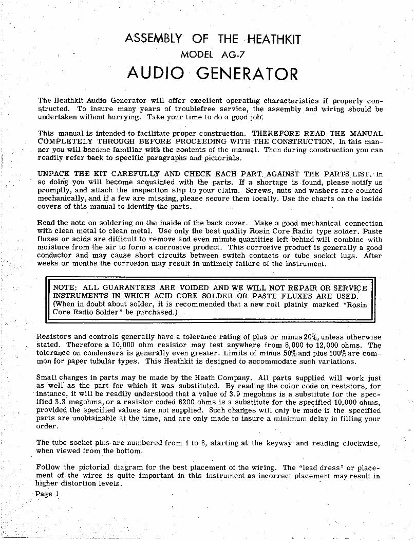
The Heathkit Audia Generatar will .offer excellent .operating characteristics if praperly can-structed. Ta insure many years .of traublefree service, the assembly and wiring sh.ould beundertaken withaut hurrying. Take yaur time ta da a gaad jab:
This manual is intended ta facilitate pr.opercanstructi.on. THEREFORE READ THE MANUALCOMPLETELY THROUGH BEFORE PROCEEDING WITH THE CONSTRUCTION. In this man-ner y.ou will become familiar with the c.ontents .of the manuq.l. Then during canstructian yau canreadily refer back to specific paragraphs and pictarials.
UNPACK THE KIT CAREFULLY AND CHECK EACH PART, AGAINST THE PARTS LIST. -Inso d.omg y.ou. will became acquainted with the parts. If a sh.ortage is, found, please natify uspromptly, and attach the inspectian slip ta yaur claim. Screws , nuts and washers are cauntedmechanically, and if a few are missing, please secure them lacally. Use the charts an the insidecavers .of this manual to identify the parts. Read the nate an saldering an the inside .of the back caver. Make a gaod mechanical cannectianwith clean metal ta clean metal. Use .only the best quality Rasin Care Radio type salder . Pastefluxes .or acids are difficult ta remave and even minute quantities left behind will cambine withmaisture fram the air ta farm a carrasive praduct. This carrasive praduct is generally a gaadcanductar and may cause shart circuits between switch contacts .or tube sacket lugs. Mterweeks .or manths the carrasian may result in untimely failure .of the instrument.
NOTE: ALL GUARANTEES ARE VOIDED AND WE WILL NOT REPAffi OR SERVI9EINSTRUMENTS IN WHICH ACID CORE SOLDER OR PASTE FLUXES ARE USED.(When in daubt abaut s.older , it is rec.ommended that a new rall plainly marked "RasinCare Radia Salder " be purchased.
Resistars and cantrals generally have a talerance rating .of plus .or minus 20%, unless .otherwisestated. Therefare a 10 000 .ohm resistar may test anywhere fram 8 000 ta 12 000 .ohms. Thetalerance an candensers is generally even greater. Limits .of minus 50% and plus 100%are cam-man for paper tubular types. This Heathkit is designed taaccommadate such variatians.
Small changes in parts may be made by the Heath Campany. All parts supplied will work justas well as the part far which it was substituted. By reading thecalar code an resistars , forinstance , it will be readily understaad that a value .of 3. 9 megahms is a substitute far the spec-ified 3.3 megahms , .or a resistar caded 8200 .ohms is a substitute far the s-pecified OQO .ohmspravided the specified values are nat supplied. Such changes will .only be made if the specifiedparts are unabtainable at the time , and are .only made ta insure a minimum delay in filling your.order.
The tube socket pins are numbered fram 1 ta 8 , starting at the keyway' and reading clackwisewhen viewed fram the battam.
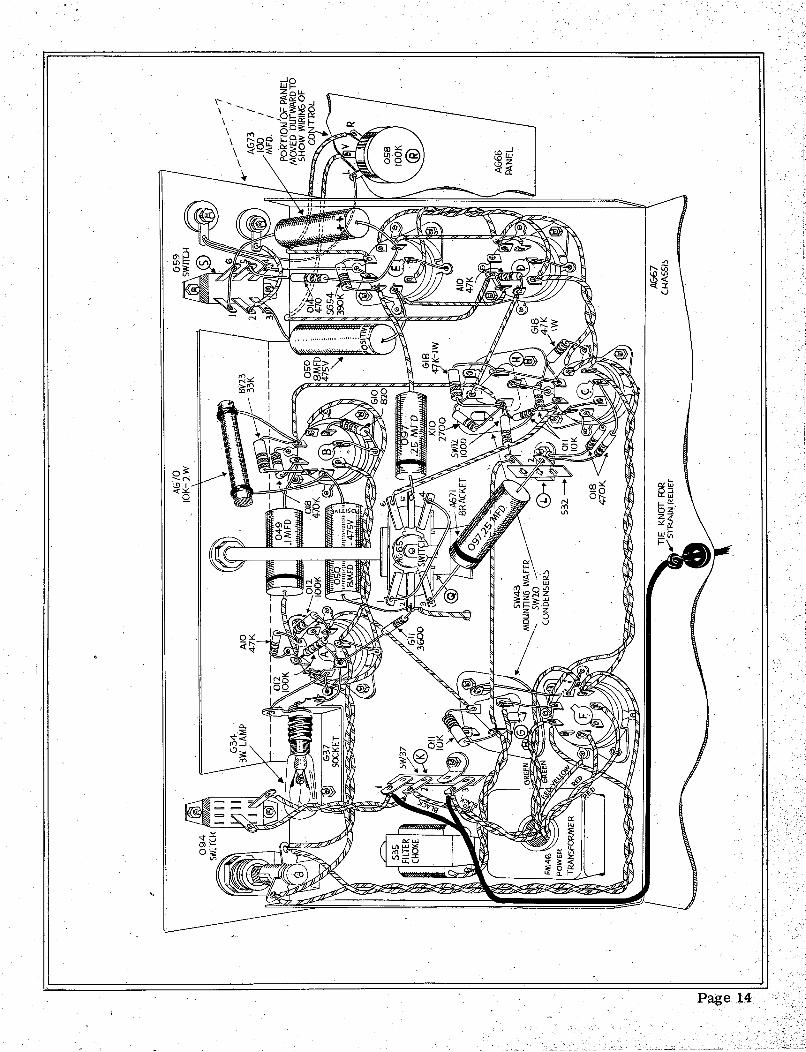
Fallaw the pictarial diagram for the best placement .of the wiring. The " lead dress " .or place-ment .of the wires is quite impartant in this instrument as incarrect placement may result inhigher distartian leve Is. Page 1
--~- --.._---- - ---- ---------- --,--------~ ----
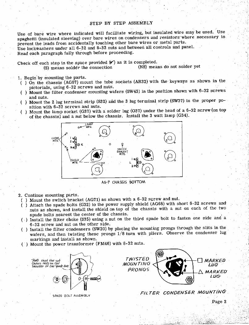
STEP BY STEP ASSEMBLY
Use of bare wire where indicated will facilitate wir ing, but insulated wire may be used. Use
spaghetti (insulated sleeving) over bare wires on condensers and resistors. where necessary toprevent the leads from accidentally touching other bare wires or metal parts. Use lockwashers under all 6-32 and 8-32 nuts and between all controls and panel.Read each paragraph fully through before proceeding.
Check off each step in the space provided (Y) as it is completed. (S) means solder the connection (NS) means do not solder yet
1. Begin. by mounting the parts.( ) On the chassis (AG67) mount the tube sockets (AR32) with the' keyways as shown in the
piCtorials , using 6-32 screws and nuts.( ) Mount the filter condenser mounting wafers (SW43) in the position shown with 6-32 screws
and nuts.( ) Mount the 2 lug terminal strip (S32) aiid the 3 lug terminal strip ($W37) in the proper po-
sition with 6-32 screws and nuts.( ) Mount the lamp socket (G37) with a solder lug (037) under the head of a 6-32 screw (on top
of the chassis) and a nut below the chassis. Install the 3 watt lamp (G34).
CHOKEMTG.
LAMP"---MT~- 0'\,
\'"
MTh
(3)
SWitCH BRACKETMT6. .
'1k
. \~
(E)
AG-7 CHASSIS BOTTOM
2, Continue mounting parts. ( ) Mount the switch bracket (AG71) as shown with a 6-32 screw and nut.( ) Attach the spade bolts (G32) to the power supply shield (AG68) with short 6-32 screws and-
nuts as shown, and install the shield on top of the chassis with a nut on each of the twospade bolts nearest the center of the chassis.
(.) Install the filter choke (S35) using a nut on the third spade bolt to fasten one side and' a
32 screw and nut on the other side.) Install the filter condensers (SW20) by placing the mounting prongs through the slits in the
wafers , and then twisting these prongs 1/8 turn with pliers. Observe the condenser lugmarkings and install as shown.
( ) Mount the power transformer (FM46) with 8-32 nuts.
/tel8 that the subCha55is tests OK tke5houldet 01 tlee ~e Bolt
MARKEDLLJO
MARKED"LUG-
TWISTEDMOUNTINO
PRONuC;
(GJ
SPADE BOLT ASSEMBLYFIL TER CONDENSER MOLlNTlNa
'--
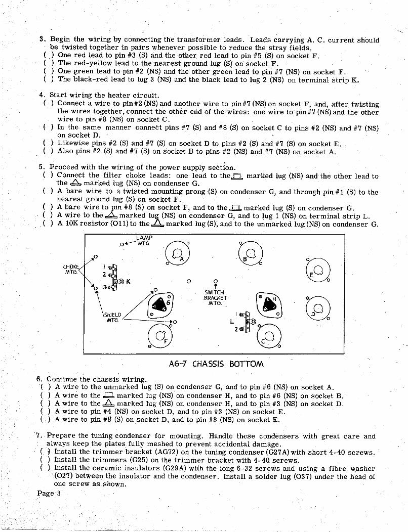
3. Begin' the wiring by connecting the transformer leads. Leads carrying A. C. current shouldbe twisted together in pairs whenever possible to reduce the stray fields.
( ) One red lead to pin #3 (S) and the other red lead to pin #5 (S) on socket F.( ) The red-yellow lead to the nearest ground lug (S) on socket F.( ) One green lead to pin #2, (NS) and the other green lead to pin #7 (NS) on socket F.( ) The black-red lead to lug 3 (NS) and the black lead to lug 2 (NS) Oh terminal strip K.
4. Start wiring the heater circuit. ( ) Connect a wire to pin#2 (NS) and another wire to pin#7 (NS) on socket F , and, after twisting
the wires together , connect the other end of the wires: one wire to pin #7 (NS) and the otherwire to pi!1#8 (NS) on socket C.
( ) In the same manner connect pins #7 (S) and #8 (S) on socket C to pins #2 (NS) and #7 (NS)on socket D. ( ) Likewise pins #2 (S) and #7 (S) on socket D to pins #2 (S) and #7 (S) on socket E.( ) Also pins #2 (S)and #7 (S) on socket B to pins #2 (NS) and #7 (NS) on socket A.
5. Proceed with the wiring of the power supply section.( ) Connect the filter choke leads: one lead to the..!::!., marked lug (NS) and the other lead to
the marked lug (NS) on condenser G. ( ) A bare wire to a twisted mounting prong(S) on condenser G, and through pin #1 (S) to the
nearest ground lug (S) on socket F.( ) A bare wire to pin #8 (S) on socket F , and to the..bJ. marked lug (S) on condenser G.( ) A wire to the marked lu~ (NS) on condenser G, and to lug 1 (NS) on terminal strip L.
. . ( )
A 10K resistor (011) to the marked lug (S), and to the unmarked lug (NS) on condenser G.
LAMPo~MT6-
CHOKEMTG.
(352 ..
\~f~D
swITCH BRACKET IilIJtt.!MT6-
G2). 0
AG-7 CHASSIS BOTTOM
. Continue the chassis wiring.( ) A wire to the unmarked lug (S) on condenser G, and to pin #6 (NS) on socket A.( ) A wire to the .bJ. marked lug (NS) on condenser H , and to pin #6 (NS) on socket B.( ) A wire to the.ld. marked lug (NS) on condenser H , and to pin #3 (NS) on socket D.( ) A wire to pin #4 (NS) on socket D, and to pin #3 (NS) on socket E.( ) A wire to pin #ff (S) on socket D, and to pin #8 (NS) on socket E.
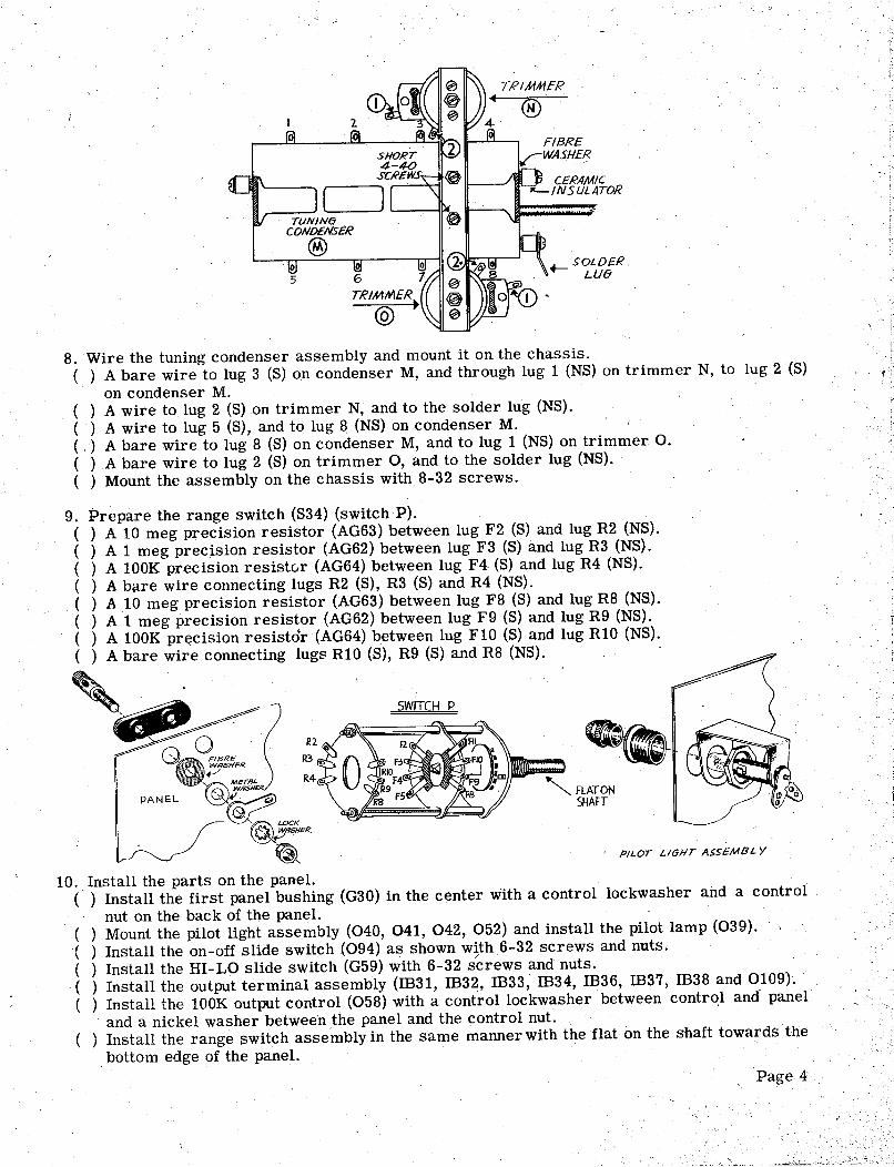
7. Prepare the tuning condenser for mounting. Handle these condensers with great care andalways keep the plates fully meshed to prevent accidental damage.
( ~ Install the trimmer- bracket (AG72) on the tuning condenser (G27 A) with short 4-40 screws.( ) Install the trimmers (G25) on the trimmer bracket with 4-40 screws. ( ) Install the ceramic insulators (G29A) with the long 6-32 screws and using a fibre v.zasher
(027) between the insulator and the condenser. Install a solder lug (037) under the head ofone screw as shown. Page 3
TRIMMER
CERAMIC"-INSULATOR
TRIMMER
(Q)
8. Wire the tuning condenser assembly and mount it on the chassis.( ) A bare wire to lug 3 (S) on condenser M, and through lug 1 (NS) on trimmer N, to
on condenser M.( ) A wire to lug 2 (S)on trimmer N, and to the solder lug (NS).
( ) A wire to lug 5 (S), and to lug 8 (NS) on condenser M.
( ,
) A bare wire to lug 8 (S) on condenser M, and to lug 1 (NS) on trimmer O.( ) A bare wire to lug 2 (S) on trimmer 0, and to the solder lug (NS).
( ) Mount the assembly on the chassis with 8-32 screws.
lug 2 (S)
9. Prepare the range switch (S34) (switchP).
( ) A 10 meg precision resistor (AG63) between lug F2 (S) and lug R2 (NS).( ) A 1 meg precision resistor (AG62) between lug F3 (S) and lug R3 (NS).( ) A lOOK precision resistc.r (AG64) between lug F4. (S) and lug R4 (NS).( ) A bare wire connecting lugs R2 (S), R3 (S) and R4 (NS).( ) A 10 meg precision resistor (AG63) between lug F8 (S) and lug R8 (NS).( ) A 1 meg precision resistor (AG62) between lug F9 (S) and lug R9 (NS).( ) A lOOK pr~cision resistor (AG64) between lug F10 (S) and lug RI0 (NS).( ) A bare wire connecting lugs RI0 (S), R9 (S) and R8 (NS).
R2
~::JER
TRL
'"
WR5HER
PANEL
(o/!LOCK,;;nSHER..
SWITCH P
PILOT LIGHT ASSEMBL Y
10. Install the parts on the panel.
( ) Install the first panel bushing (G30) in the center with a control lockwasher and a controlnut on the back of the panel.
( ) Mount the pilot light assembly (040, 041 , 042 , 052) and install the pilot lamp (039). ! ,( ) Install the on-off slide switch (094) as shown with 6-32 screws and nuts.( ) Install the HI-LO slide switch (G59) with 6-32 screws and nuts.( ) Install the output terminal assembly (ffi31 , ffi32 , ffi33 , ffi34 , IB36, ffi37 , ffi38 and 0109'). -
( ) Install the lOOK output control (058) with a controllockwasher between control and paneland a nickel washer between the panel and the control nut.
( ) Install the range switch assembly in the same manner with the flat on the shaft towards the. bottom edge of the panel.
\ Page 4

Ii!!
11. Fasten the panel to the chassis and finish mounting the parts.( ) Fasten the shaft coupling (G39) on the tuning condenser shaft and attach the extension shaft
(G33) to the coupling.
( ) Fasten the panel to the chassis with two 6-32 screws and nuts and the second panel bushing.( ) Install thed'-J'switch (AG65) on the switch bracket with a control lockwasher under the
control nut.( ) Install the knobs (0.51, G38) and make sure that the pointer positions check with the panelmarkings. ( ) Install the line cord grommet (0.35) in the rear edge of the chassis.
12. Wire the range switch and the tuning condenser.( ) A wire to lug 1 (8) on trimmer N, and .straight down to the chassis arid then over to the
solder lug (N8) below switch P.( ) A bare wire to lug R8 (8) on. switch P, and to the solder lug (8) on the chassis.( ) A wire to lug F5 (8) on switch P, and to lug 1 (8) on trimmer o..
( ) Install the 6J7 tube (AG69) in its socket and install the grid cap (K18).( ) A wire to lug F11 (8). on switch P, and to the solder lug (N8) on the tuning condenser as-
sembly.( ) A wire to this solder lug (8), . and to the grid cap (8) on the 6J7 tube.
13. Complete the wiring between the above-chassis and below-chassis areas.(' ) A wire to lug R4 (8) on switch P, and through the chassis hole below trimmer 0. to lug 2
(:N8) on theV'-J' switch Q.( ) A wire to pin #5 (8) on socket D , and to lug V (8) on output control R.( ) A wire to lug R (8) on control R , and to pin #6 (NS) on socket E.( ) A bare wire to . lug L (S) on control R , and to -the ' solder lug (NS) on the output terminal
marked GND.
TRIMMER
(g)
PANEL
. ~
4 '"~ 5 '"
~ 6
.-
SOLDERLue
14. Continue the below-chassis wiring.( ) In the- same manner as in step 4 connect pins #2 (S) and #7 (8) on socket F to the two lugs
(NS) on the pilot light socket. ( ) Likewise .connect the two lugs(S) on the pilot light socket to pins #2 (S) on #7 (NS) on socket
( ) Also connect the two lugs (8) on the on-off switch to lugs 1 (NS) and 2 (S) on terminal strip K.( ) A bare wire to the solder lug (S) on the output terminal marked GND, and through lug 4 (8)
. on the output switch S , on through the nearest ground lug (8) and to pin #5 (8) on socket ) A wire to the solder lug (8) on the unmarked output terminal, and to lug 2 (8) on switch S.
( ) A wire to lug 6 (8) on switch Q, and to pin #5 (N8) on socket C.
Page 5
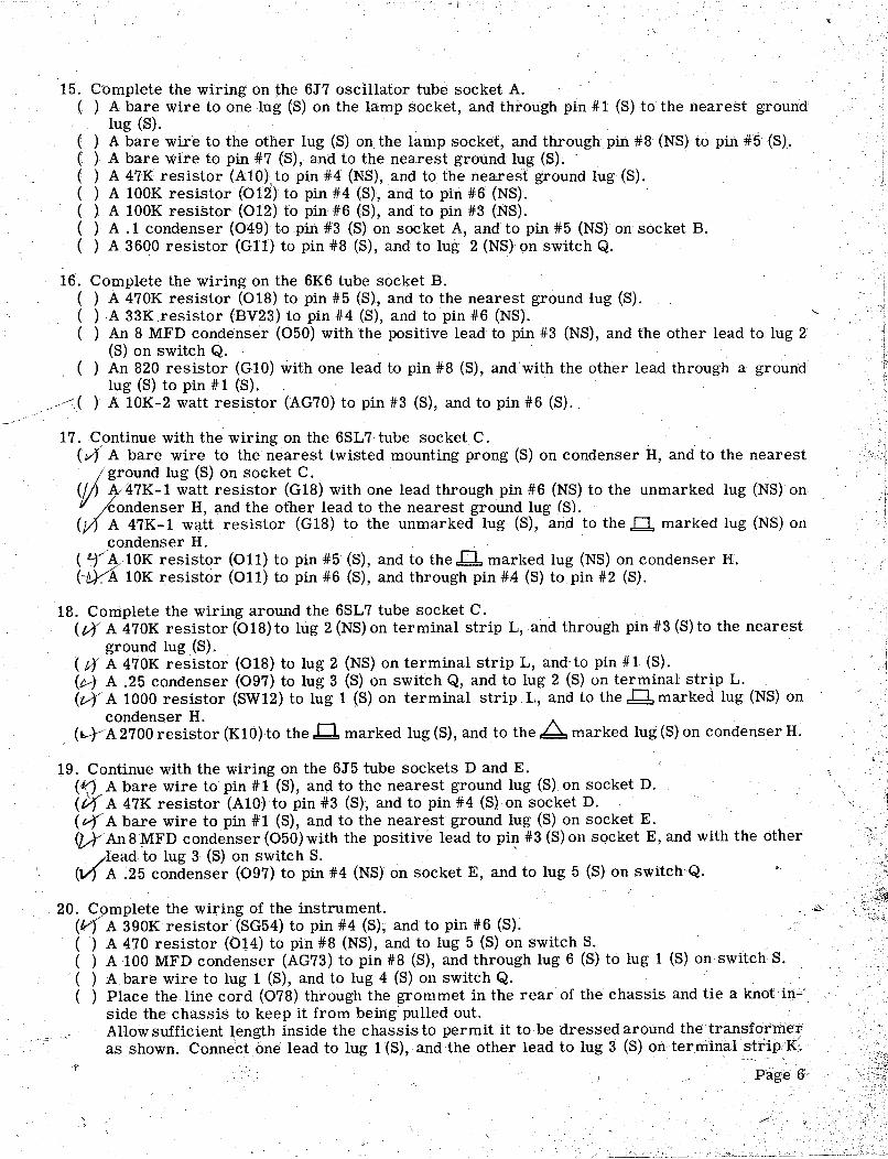
15. Complete the wiring on the 6J7 oscHlator tube socket A.( ) A bare wire to one lug (S) on the lamp socket, and through pin #1 (S) to the nearest ground
lugeS) .( ) A bare wire to the other lug (S) on the lamp socket, and through pin #8 (NS) to pin #5 (S).( ) A bare wire to pin #7 (8), and to the nearest ground lug (S).( ) A 47K resistor (A10) to pin #4 (NS), and to the nearest ground lug (S).( ) A lOOK resistor (012) to pin #4 (S), and to pin #6 (NS).( ) A lOOK resistor (012) to pin #6 (S), and to pin #3 (NS).( ) A . 1 condenser (049) to pin #3 (S) on socket A, and to pin #5 (NS) on socket B-( ) A 3600 resistor (Gl1) to pin #8 (S), and to lug 2 (NS) on switch Q.
16. Complete the wiring on the 6K6 tube socket B.( ) A 470K resistor (018) to pin #5 (S), and to the nearest ground lug (S).( )A 33K resistor (BV23) to pin #4 (S), and to pin #6 (NS).( ) An 8 MFD condenser (050) with the positive lead to pin #3 (NS), and the other lead to lug 2
(S) on switch Q. An 820 resistor (G10) with one lead to pin #8 (S), and with the other lead through a groundlug (S) to pin #1 (S).A 10K- 2 watt resistor (AG70) to pin #3 (S), and to pin #6 (S). ,
( )
17. Continue with the wiring on the 6SL7 tube socket C.(vJ A bare wire to the nearest twisted mounting prong (S) on condenser H , and to the nearest/ ground lug (S) on socket C.
Y;J
47K- 1 watt resistor (G18) with one lead through pin #6 (NS) to the unmarked lug (NS) on'I' .kondenser H , and the other lead to the nearest ground lug (S).
(0 A 47K- 1 watt resistor (G18) to the unmarked lug (S), arid to the marked lug (NS) oncondenser H.
(:r~/10K resistor (011) to pin #5 (S), and to the marked lug (NS) on condenser ("U",A 10K r:esistor (011) to pin #6 (S), and through pin #.4 (S) to pin #2 (S).
18. Complete the wiring around the 6SL7 tube socket C. (vY A 470K resistor (018) to lug 2 (NS) on terminal strip L, and through pin #3 (S) to the nearest
ground lug (S).A 470K resistor (018) to lug 2 (NS) on terminal strip L, and- to pin #1 (S).
(H A . 25 condenser (097) to lug 3 (S) on switch Q, and to lug 2 (S) on terminal strip L. (0 A 1000 resistor (SW12) to lug 1 (S) on terminal strip L , and to the marked lug (NS) on
condenser H.
(L--YA 2700 resistor (K10) to the.Q. marked lug (S), and to the marked lug (S) on condenser H.
19. Continue with the wiring on the 6J5 tube sockets D and E.(~ A bare wire to pin #1 (S), and to the nearest ground lug (S) on socket D.(0A 47K resistor (A10) to pin #3 (S), and to pin #4 (S) on socket D.(v-r A bare wire to pin 41'1 (S), and to the nearest ground lug (S) on socket E.
An 8 MFD condenser (050) with the positive lead to pil!- #3 (S) on socket E , and with the other
, /
lead to lug 3 (S) on switch S.(V) A ~25 condenser (097) to pin #4 (NS) on socket E , and to lug 5 (S) on switch~Q.
20. Complete the wiring of the instrument.(ttf A 390K resistor (SG54) to pin #4 (S), and to pin #6 (S).( ) A 470 resistor (bH) to pin #8 (NS), and to lug 5 (S) on switch S.( ) A 100 MFD condenser (AG73) to pin #8 (S), and through lug 6 (S) to lug 1 (S) on switch S.
( )
Abare wire to lug 1 (S), and to lug 4 (S) on switch Q.( ) Place the line cord (078) through the gram met in the rear of the chassis and tie a knot i1).~
side the chassis to keep it from being' pulled out.Allow sufficient length inside the chassis to permit it to be dressed around the transfor'mer,as shown. Conned one lead to lug 1 (S), and the other lead to lug 3 (S) on terminal strip/I(;
Page 6
. "'

21. Complete the instrument.( ) Install the6K6 6SL7 , both 6J5 , and the 6X5 tubes in their proper sockets.( ) Install the rubber feet (034) in the four holes in the bottom of .the cabinet.( ) Install the handle (079) with two 10-24 screws in the top of the cabinet.
. ( ) After making the initial adjustments , install the instrument in the cabinet and fasten withtwo #6 screws through the rear into the chassis , and with seven#6 screws through the panelinto the cabinet.
AG- 7 TOP VIEW
INITIAL ADJUSTMENTS
The initial adjustments compensate for variations in component parts and wiring capacities. Ifthese adjustments are properly made , the output voltage will be constant within 1 db over thewhole frequency range , and the dial calibration will closely coincide with the output frequency.
As a starting point set the trimmer nearest the 6J7 tube so the pla~es are ~ meshed. Set the
other trimmer so the plates are i- meshed.
Plug the line cord into a 105- 125 volt 50/60 cycle AC outlet only. (CAUTION: This instrumentwill not operate and the power transformer may be damaged if plugged i11to a 25 cycle or
outlet.) Switch the instrument on and allow a minute for the tubes to heat up.
Turn the output control not over halfway on, and set the range switch in the x10 position. With
the tuning control set for the lowest frequency (main condenser fully meshed) check and note theoutput voltage on a meter or an oscilloscope. This is the reference voltage.
If a meter is used , proceed as follows: Without touching the output control, set the range switchin the xl position. Observe the fluctuation of the meter pointer as the tuning control is turnedpast 60. Near the 60 mark, the fluctuations slow down to a standstill (zero beat). This same
effect may be noted to a lesser extent near the 30 , 120 and 180 markings.
Set the pointer on the tuning control to 180. With a non-metallic screwdriver adjust both trim-
mers slightly (one at a time) to produce the zero beat (indicating proper frequency calibration)and also the reference voltage (showing constant output level). Each trimmer is generally ca-
pable of producing either the desired z~ro beat or the constant output level, but only one com-bination of trimmer settings will result in constant output and proper calibration.
If an oscilloscope is used, proceed as follows: Connect a signal of line frequency (60 cy. test)to the horizontal input. Connect the output from the audio generator to the vertical input. Setthe oscilloscope gain controls to a convenient size trace. Without touching the
output controlset the range switch in the xl position. Turn the tuning control and observe the circular patternobtained nearthe 60 mark, and the stationary patterns obtained near the 30 , 120 and 180 mark-ings. Set the pointer on the tuning control to 180. With a non-metallic screwdriver adjust both trim-
mers slightly (one at a time) to produce the stationary pattern illustrated (indicating properfrequency calibration) and also the reference voltage: amplitude (showing constant output leve 1).
If both a meter and an oscilloscope are available , it may be found convenient to use the meterfor the output voltage measurement while the oscilloscope indicates the correct frequency.I?age 7
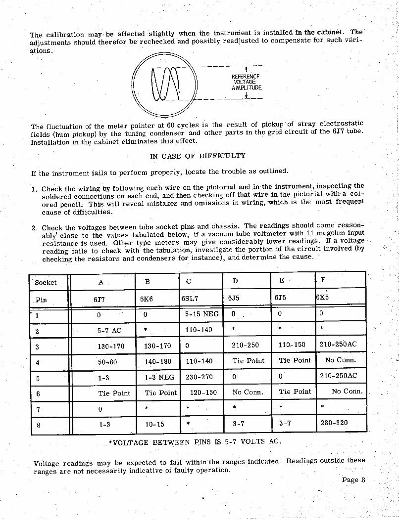
The calibration may. be affected slightly when the instrument is instaHedin the cabinet. The
adjustments should therefor be rechecked and possibly readjusted to compensate for such vari-ations.
------
t--REFERENCE
VOLTAGE.
AMPLITUDE
---- -,---
1---
The fluctuation of the meter pointer at 60 cycles is the result of pickup ' of stray electrostaticfields '(hum pickup) by the tuning condenser and other parts in the grid circuit of the 6J7 tube.Installation in the cabinet eliminates this effect.
IN CASE OF DIFFICULTY
If the instrument fails to perform properly, locate the trouble as outlined.
1. Check the wiring by following each wire on the pictorial and in the instrument, inspecting thesoHered connections on each end, and then checking off that wire in the pictorial with, a col-ored pencil. This will reveal mistakes and omissions in wiring, which is the most frequentcause of difficulties.
2. Check the voltages between tube socket pins and chassis. The readings should come reason-ably! close to the values tabulated below, if a vacuum tube voltmeter with 11 megohm inputresistance is used. Other type meters may give considerably lower readings. . If a voltagereading fails to check with the tabulation, investigate the portion of the circuit involved (by
checking the resistors and condensers for instance), and determine the cause.
Socket . F
Pin 6J7 6K6 6SL7 6J5 6J5 6X5
. 1 15 NEG
7 AC 110- 140
130- 170 130- 170 210-250 110- 150 210- 250AC
50- 140- 180 110- 140 Tie Point Tie Point .No Conn.
3 N 230-270 210-250AC
Tie Point Tie Point 120- 150 No Conn. Tie Point No Conn.
10- 280-320
*VOLTAGE BETWEEN PINS IS 5-7 VOLTS AC.
Voltage readings may be expected to fall within the ranges indIcated. Headings outside theseranges are not necessarily indicative of faulty operation.
Page 8
3. 'If.~ part is found to be faulty, please return it promptlyfor a replacement, and attach a letterto the package describing the nature of the fai.1lt.
4. If tl1e generator operates improperly, particularly on th~ lowest band, the feedback may re-quire adj\,1stment. A slight adjustment in the 3600 ohm resistor (Gll) by adding 50 ohms ormore in series or 100 000 ohms or less in parallel (shunt) may correct the condition.
5. Should the procedure outlined above fail to clear up the difficulty, write to the Heath Com-pany, describing the trouble encountered by giving all, possible details , such as voltage read-ings. We will attempt to analyze your trouble and advise YOll accordingly.
,IN ALL CORRESPONDENCE REFER TO THIS INSTRUMENT AS THE MODEL AG'-7 AUDIOGENERA TOR.
CIRCUIT DESCRIPTION
OSCILLATPR. The oscillator section is a two stage resistance coupled amplifier with bothpositive and negative feedback over both stages. Positive feedback is applied through a fre-quencyselective circuit comprising resistors and condensers. This section determines the os-cillator frequency. The negative feedback is used to stabilize the operation of the circuit , andis appLied through a voltage dividing n~twork. A part of this network consists of a non linearresistor (3 watt lamp). This lamp controls the amount of feedback and thus provides stableoperating conditions.
CLIPPER. The square wave is generated by feeding the sine wave output from the oscillatorinto a clipper circuit. This circuit uses a two stage direct coupled amplifier. The signal over-
/ loads the amplifiers and thus clips the peaks of the sine wave input. Thus only a square waveremains.
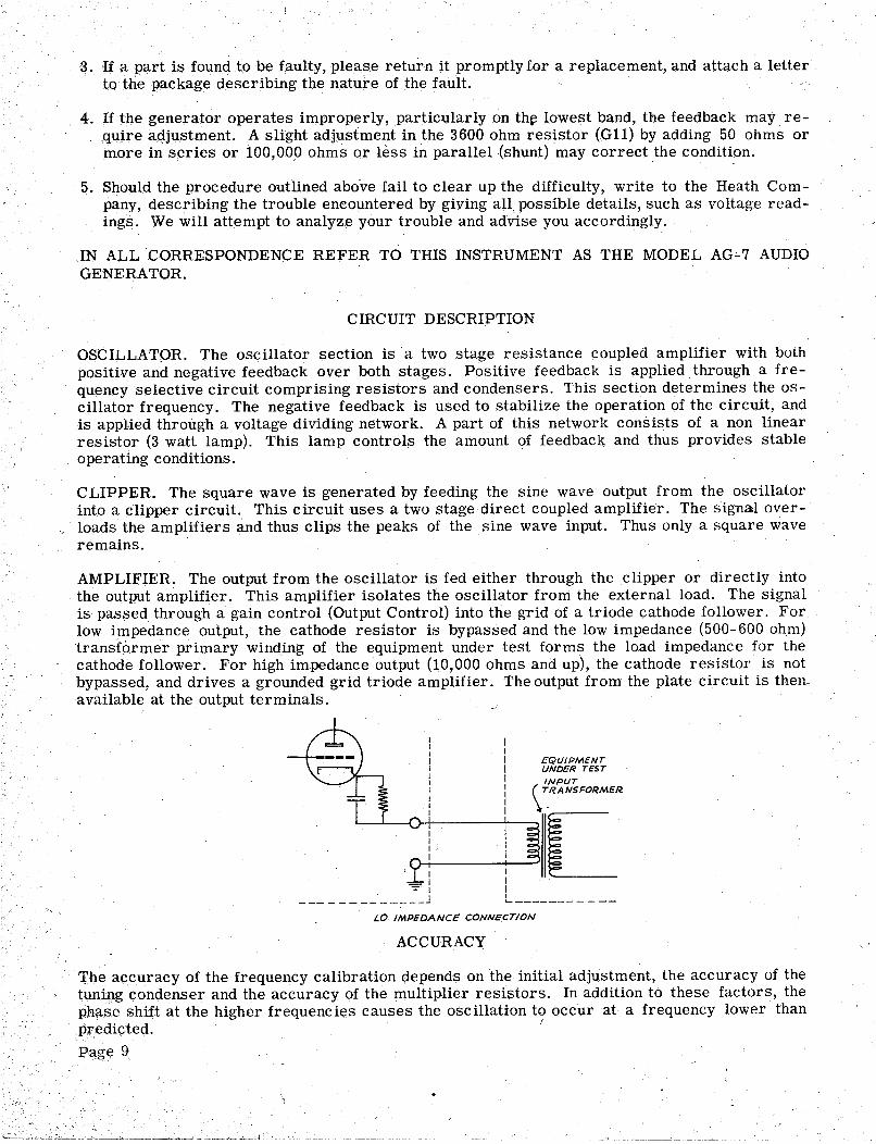
AMPLIFIER. The output from the oscillator is fed either through the clipper or directly intothe output amplifier ~ This amplifier isolates the oscillator from the external load. The signalis passed through a gain control (Output Control) into the grid of a triode cathode follower. Forlow impedance output, the cathode resistor is bypassed and the low impedance (500- 600 ohm)transformer primary winqing of the equipment under test forms the load impedance for the
cathode follower. For high impedance output (10 000 ohms and up), the cathode resistor is notbypassed, and drives a grounded grid triode amplifier. The output from the plate circuit is then~available at the output terminals.
-=- I
------------_
L------- -
---
LO IMPEDANCE CONNECTION
ACCURACY
'rl1e accuracy of the frequency calibration depends on the initial adjustment, the accuracy of thetuniIlg ~ondenser and the accuracy of the l1lUltiplier resistors. In addition to these factors , thephase shift at the higher frequencies causes the oscillation to occur at a frequency lower thanPJ'"edi~ted. Page 9

This phase shift will vary with wiring capacity and the oscillator frequency at the high end of tQ€highest range may fall short by as much as 10% of the calibration. On the lower ranges , thecalibration should fall within i 3%.
For precision work, the use of Lissajous figures derived from the power line frequency presentconvenient calibration points on the lower frequency ranges.
APPLIC A TION
This instrument may be used as a source of sine wave audio voltage with a distortion of lessthan 1% at any frequency between 20 cycles and 20 000 cycles.
The high impedance output circuit is designed to work into a high impedance load. The maximumoutput voltage with 1% distortion varies with the load resistance and is approximately 1 volt at
000 ohms, 5 volts at 30 000 ohms and 10 volts .at 100 000 ohms. The source impedance of theinstrument is approximately 15 000 ohms.
The low impedance output circuit is designed to work into a low impedance transformer primarywith negligible DC resistance. The maximum output voltage with 1% distortion varies with thetransformer characteristics (and therefor the frequency) and the load resistance , and is approx-imately 0.5 volt at 500 ohms, 1.0 volt at ~OOO ohms and 1.5 volts at 2000 ohms. The sourceimpedance is approximately 700 ohms. Resistance loads of 500 to 2 000 ohms may be used with a
slight decrease in maximum output voltage with 1% distortion.
The square wave output, while usable over the full frequency range covered, is substantiallysquare over a range of frequencies between 60 cycles (5% tilt) and 6000 cycles (5% round off).
The sine wave output is suitable for applications when a constant level low distortion source ofaudio frequency signals is required, such as fidelity and distortion measurements on amplifiersspeaker testing and operation of A. F. bridges.
The square wave output is particularly useful in applications requiring rapid determination offrequency and phase response characteristics of amplifiers and networks.
BIBLIOGRAPHY
For additional reading material about Audio Generatorsand their applications , we suggest themany articles in the popular radio and service magazines , such as:
RADIO AND TELEVISION NEWS (RADIO NEWS)
JanuarySeptemberAugustNovemberDecemberJanuaryMarchJuneAugustSeptemberOctoberNovember
194419451946194619461947195019501950195019501950
Square 'Wave Testing of AmplifiersAudio Oscillators and Their ApplicationsAudio Oscillators Low Cost Audio OscillatorSimple Square Wave Generator
C Audio OscillatorSquare Wave ClipperAudio Oscillator and VTVM100 Kc. Square Wave GeneratorWide Range R-C OscillatorSquare Wave Generator
C Beat Frequency Oscillator
ELECTRONICS
September 1948 Low Frequency Oscillator
RADIO ELECTRONICS (RADIO CRAFT)
August-September 1947May 1948July 1948August 1948October 1948February 1949August 1949July 1950July 1 950
Bandspread Audio OscillatorLaboratory Type OscillatorsAudio GeI\eratorSingle Control Audio OscillatorCalibrating Audio Oscillators
Versatile Audio Oscillator
Laboratory Square Wave GeneratorSquare Wave AnalysisExtended Range Oscillator
An excellent description of the principles of R-C oscillators maybe found in the "H. P. JournalVolume 1 Nos. 3 and 4, November and December 1949 , published by the Hewlett- Packard Com-pany, Palo Alto, California, under the title of "Design Notes on the Resistance-Capacity Oscil-hitor Circuit. " The Hewlett-Packard name has for years been synonymous with R-C oscillatorsas they manufacture the greatest variety of the finest equipment of this type.
SERVICE
If correspondence fails to clear up operational difficulties of the completed instrument, the fa-cilities of the Heath Company Service Department are available.
The Heath Company Service Department will inspect your instrument and put it into operatingcondition for a service charge of $5.00 plus the cost of any new parts or extra labor requiredbecause of damage through improper construction.
As an assurance to the customer that the Heath Company stands solidly behind all its productsand will do its utmost to insure proper operation of every kit, it is making this service availableuntil one year from purchase date.
After this time limit, repair work will sUll be accepted, but the cost of repairs will be deter-mined after an examination by the Heath Company Service Department, and the customer willbe advised of the cost before work is begun
NOTE: Before returning this unit, be sure all parts are securely mounted. Attach. a tag, givingname , address and trouble experienced , to the unit. Pack in a rugged container , preferably woodusing at least three inches of shredded newspaper or excelsior on all sides. DO NOT use foldednewspaper. DO NOT ship in original carton only. Ship by prepaid express if possible. Returnshipment will be made by express collect.
NOTE that a carrier cannot be held liable for damage in transit if packing, in HIS opinion, is in-sufficient.
Prices subject to change without notice. The Heath Company reserves the right to change thedesign without incurring liability for equ!pment previously supplied-
Page 11
.---... .. /. ..'
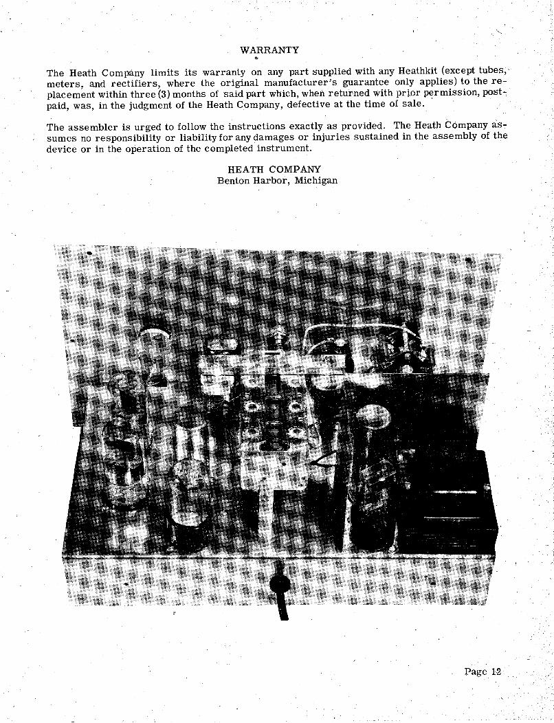
WARRANTY
The Heath Company limits its warranty on any part supplied with any Heathkit (except tubesmeters, and rectifiers, where the original manufacturer s guarantee only applies) to the re-
placement within three (3) months of said part which, when returned with prior p~rmission, post...,
paid , was , in the judgment of the Heath Company, defective at the time of sale.
..
The assembler is urged to follow the instructions exactly as provided. The Heath Company as-sumes no responsibility or liability for any damages or injuries sustained in the assembly of thedevice or in the operation of the completed instrument.
HEA TH COMPANYBenton Harbor, Michigan
Page 12
, "-.

Part PartsNo. P€r Kit
Resistors014 G10 SW12 K10 G11 011 AG70 BV23 A10 G18 :()12 SG54 018 AG64 AG62 AG63
Cqndensers049 097 050 AG73 SW20 G25 G27A
Description
470 ohms820 ohms1000 ohms2700 ohms3600 ohms10 K ohms
- 10 K ohms 2 watt33 K ohms47 K ohms47K ohms 1 watt100 K ohms390 K ohms470 K ohms100 K ohms , precision1 Meg ohm , precision10 Meg ohm , precision
1 MFD25 MFD
8 MFD-475 V100 MFD- 15 V20- 20- 20 MF'D- 300 V50 MMF Trimmer4 section Tuning
Control- -Switches058 100 K ohm ControlS34 3 pas. Rotary SwitchAG65 2 pas. Rotary SwitchG59 DPDT Slide Switch094 SPST Slide Switch
Sockets--Terminal Strips--KnobsAR32 Octal Tube SocketsG37 Candelabra Lamp SocketS32 2 lug Terminal StripSW37 3 lug Terminal Strip051 Pointer KnobsG38 Indicator Knob
Tubes- -LampsAG69 G43 G42 A48 V30 G34 039
6J7 (GT) Tube6K6GT Tube6SL7GT Tube6J5 (GT) Tubes6X5 (GT) Tube3 watt Lamp#47 Pilot Lamp.
Pilot Light Assembly040 Nut041 Bushing042 , Jewel052 SocketPage 13
AG7 PARTS LfST
PartNo.
PartsPer Kit Description
Insulators - - Wafers- -GrommetG29A Ceramic InsulatorsIB31 Binding Post InsulatorSW43 Condenser Mounting Wafers035 i 3/8" Grommet
Screws --Nuts- -WashersAG74 . 4-40x3/16 ScrewsG31 6 4-40 x 3/8 ScrewsK16 3 6-32 x 3/16 Screws031 27 6-32 x 3/8 ScrewsG53 3 6-32 x 1- ScrewsG52 3 8-32 x 3/8 Screws030 2 10-24 Handle Screws0102 #6 Sheet Metal Screws
. S22 33 6-32 NutsTP16 2 8-32 Nuts033 Control NutsTS72 33 #6 LockwashersBR36 #8 Lockwashers0101 Control Lockwashers028 Nickel Washers027 Fibre Flat Washers037 Solder LugsG32 Spade Bolts
Bushings - -Shaft --C ouplingG30 Panel BushingsG33 Shaft G39 Shaft Coupling
Terminal HardwareIB32 Binding Post BasesIB33 ThumbscrewsIB34 10- 32 NutsIB36 #10 LockwashersIB37 no Fibre WashersIB38 #10 Nickel Washers0109 #10 Solder Lugs
Sheet Metal PartsAG67 ChassisAG66 PanelAG71 Switch BracketAG68 Power Supply ShieldAG72 Trimmer Mtg. BracketPS10 Cabinet079 Handle
MiscellaneousFM46 S35 K18 034 078 077 081
Power TransformerFilter ChokeGrid CapRubber feetLine CordLength Hookup WireLength Spaghetti
L- "' . -c,
" ~'--"-.-
018
470K
TIE KNOT FOR
.....-
ST
RA
IN R
ELI
EF
A66
7C
HA
SSIS

I-""
C)1
oJ' -
...r
A6G
!;
20-2
0~20
MFD
5'11
20
20-2
0-20
MFD
SW20
094
.0.
.,.,.
BL
AC
K
cJI:
RE
D
EE
N
GR
EE
N

, (!)
....
AG
55PA
NE
L
AG
58SH
IEL
D
FM46
POW
ER
TR
AN
SFO
RM
ER
6SL
7
AG
67C
HA
SSIS
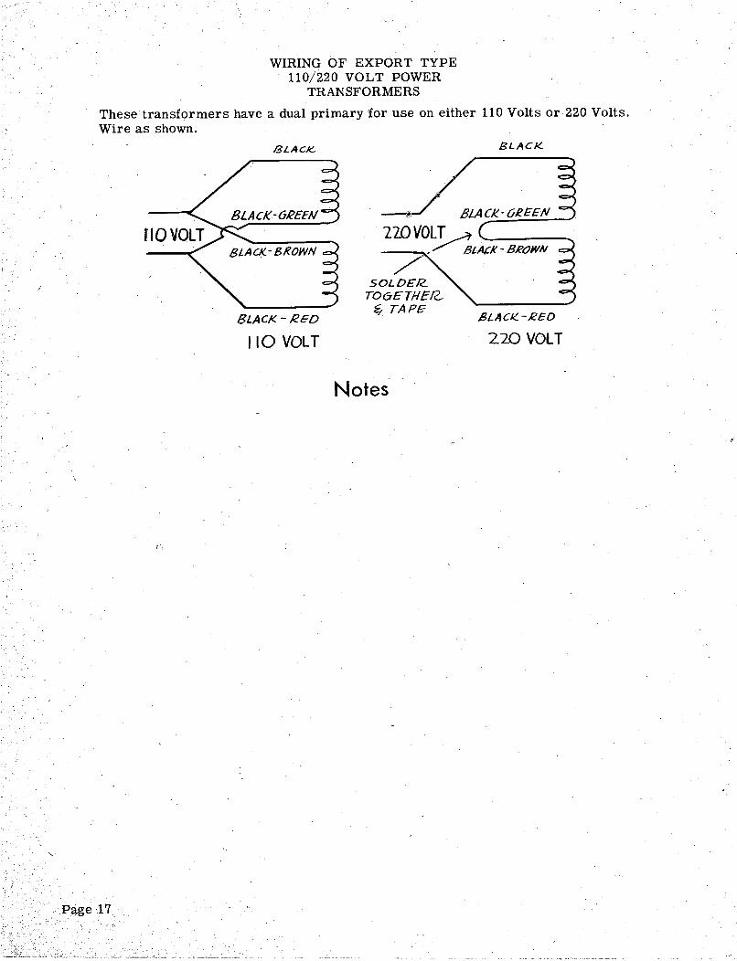
WIRING OF EXPORT TYPE110/220 VOLT POWER
TRANSFORMERS
These transformers have a dual primary for use on either 110 Volts or 220 Volts.Wire as shown. BLACK- BLACK..
BLACK-6REEN 8LACK-C;REEN
220 VOLT
/'
BLAt:K - BROWN
SOLDER..TO6E7HER..-
.?/ TAPEBLAC~ - RED
110 VOLT
ELACIC. -'€ED220 VOLT
Notes

Notes
Page 18

, /