Embed Size (px)
Citation preview
S a v e s p a c e , s a v e w i r i n g , s a v e t i m e
G-SERIES SERVO SYSTEM
E n h a n c e d p e r f o r m a n c e »M EC H AT RO L I N K- I I »
C o m p a c t s i z e »
Speed
Speed
Torque
Torque
Command speed
Command speed
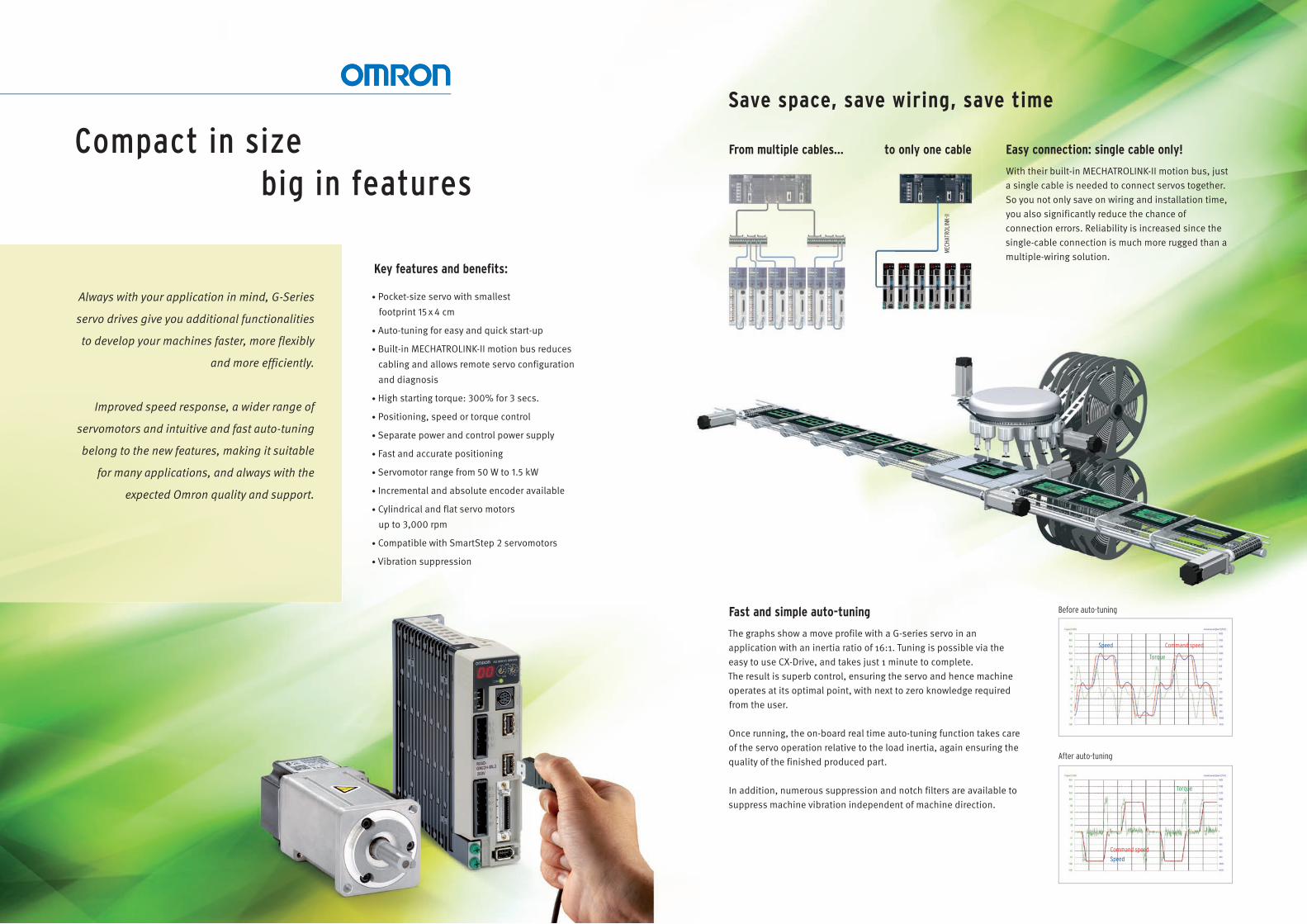
Fast and simple auto-tuning
The graphs show a move profile with a G-series servo in an application with an inertia ratio of 16:1. Tuning is possible via the easy to use CX-Drive, and takes just 1 minute to complete. The result is superb control, ensuring the servo and hence machine operates at its optimal point, with next to zero knowledge required from the user.
Once running, the on-board real time auto-tuning function takes care of the servo operation relative to the load inertia, again ensuring the quality of the finished produced part.
In addition, numerous suppression and notch filters are available to suppress machine vibration independent of machine direction.
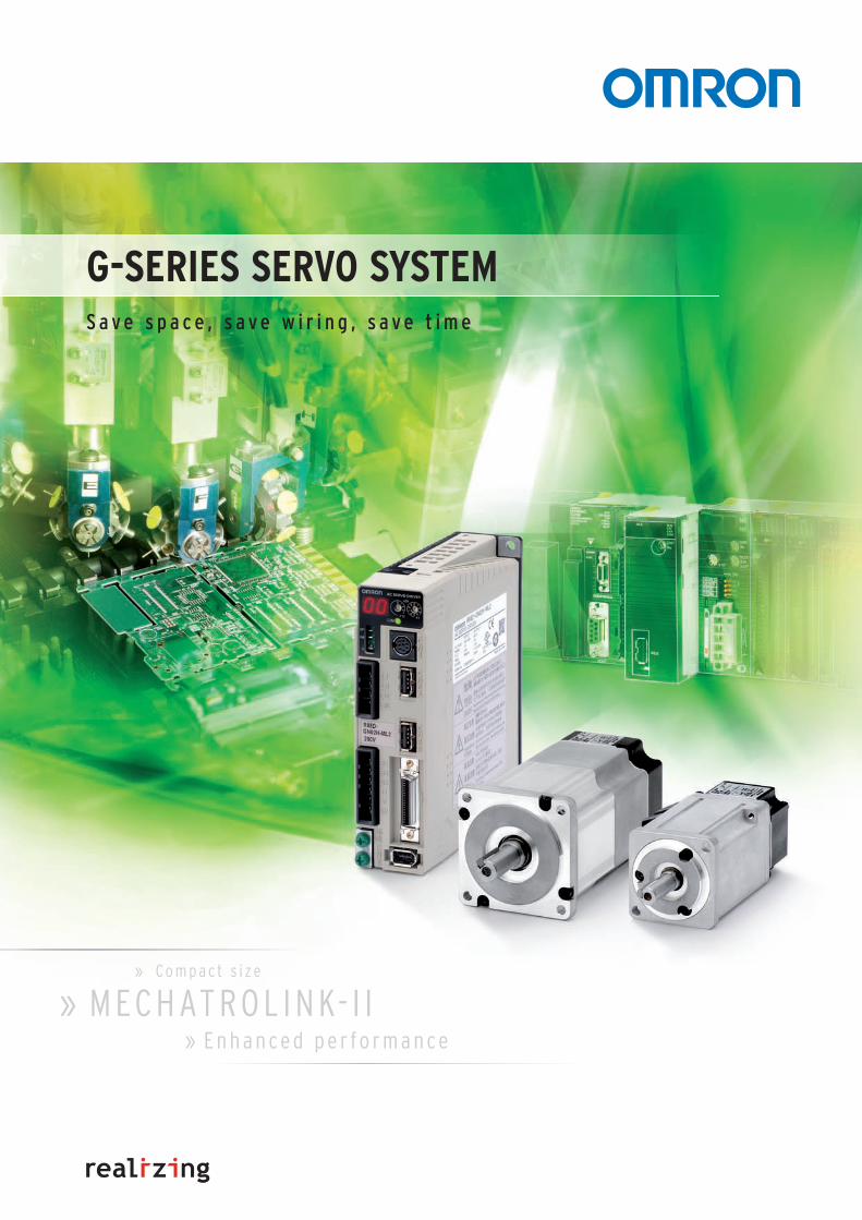
From multiple cables...
MEC
HATR
OLIN
K-II
Easy connection: single cable only!
With their built-in MECHATROLINK-II motion bus, just a single cable is needed to connect servos together. So you not only save on wiring and installation time, you also significantly reduce the chance of connection errors. Reliability is increased since the single-cable connection is much more rugged than a multiple-wiring solution.
to only one cableCompact in sizebig in features
Save space, save wiring, save time
Before auto-tuning
After auto-tuning
Always with your application in mind, G-Series
servo drives give you additional functionalities
to develop your machines faster, more flexibly
and more efficiently.
Improved speed response, a wider range of
servomotors and intuitive and fast auto-tuning
belong to the new features, making it suitable
for many applications, and always with the
expected Omron quality and support.
Key features and benefits:
• Pocket-size servo with smallest
footprint 15 x 4 cm
• Auto-tuning for easy and quick start-up
• Built-in MECHATROLINK-II motion bus reduces
cabling and allows remote servo configuration
and diagnosis
• High starting torque: 300% for 3 secs.
• Positioning, speed or torque control
• Separate power and control power supply
• Fast and accurate positioning
• Servomotor range from 50 W to 1.5 kW
• Incremental and absolute encoder available
• Cylindrical and flat servo motors
up to 3,000 rpm
• Compatible with SmartStep 2 servomotors
• Vibration suppression
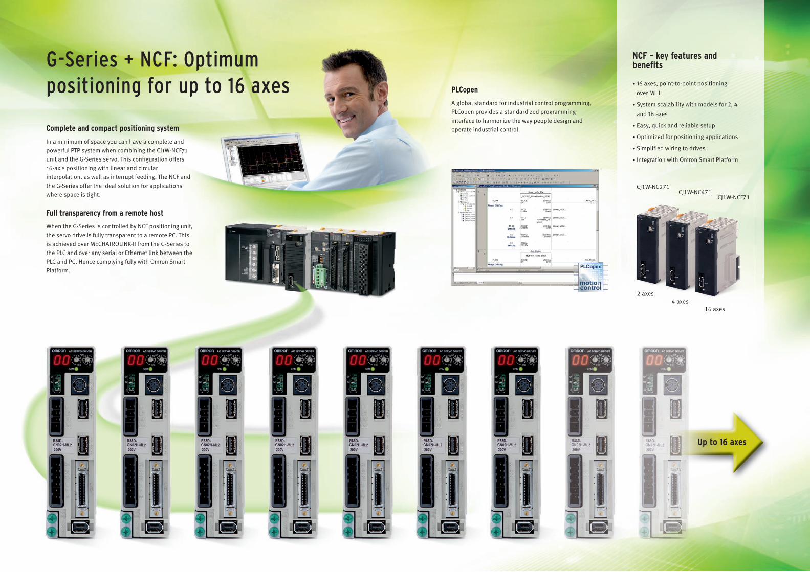
NCF – key features and benefits
• 16 axes, point-to-point positioning
over ML II
• System scalability with models for 2, 4
and 16 axes
• Easy, quick and reliable setup
• Optimized for positioning applications
• Simplified wiring to drives
• Integration with Omron Smart Platform
Complete and compact positioning system
In a minimum of space you can have a complete and powerful PTP system when combining the CJ1W-NCF71unit and the G-Series servo. This configuration offers 16-axis positioning with linear and circular interpolation, as well as interrupt feeding. The NCF and the G-Series offer the ideal solution for applications where space is tight.
Full transparency from a remote host
When the G-Series is controlled by NCF positioning unit, the servo drive is fully transparent to a remote PC. This is achieved over MECHATROLINK-II from the G-Series to the PLC and over any serial or Ethernet link between the PLC and PC. Hence complying fully with Omron Smart Platform.
Up to 16 axes
G-Series + NCF: Optimum positioning for up to 16 axes
CJ1W-NC271
CJ1W-NCF71CJ1W-NC471
2 axes4 axes
16 axes
PLCopen
A global standard for industrial control programming, PLCopen provides a standardized programming interface to harmonize the way people design and operate industrial control.
6 AC servo systems
R88D-GN@/R88M-G@
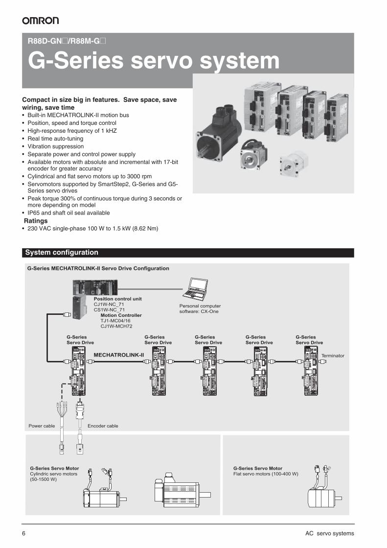
G-Series servo systemCompact in size big in features. Save space, save wiring, save time• Built-in MECHATROLINK-II motion bus • Position, speed and torque control• High-response frequency of 1 kHZ• Real time auto-tuning • Vibration suppression• Separate power and control power supply• Available motors with absolute and incremental with 17-bit
encoder for greater accuracy• Cylindrical and flat servo motors up to 3000 rpm• Servomotors supported by SmartStep2, G-Series and G5-
Series servo drives• Peak torque 300% of continuous torque during 3 seconds or
more depending on model• IP65 and shaft oil seal available Ratings• 230 VAC single-phase 100 W to 1.5 kW (8.62 Nm)
System configuration
G
IM
SP
COMX10
32
10 ADRAC SERVO DRIVER
X1
678
9 0 1
23
45
G
IM
SP
COMX10
32
10 ADRAC SERVO DRIVER
X1
678
9 0 1
23
45
G-Series Servo MotorFlat servo motors (100-400 W)
Encoder cablePower cable
Personal computersoftware: CX-One
G-SeriesServo Drive
Position control unitCJ1W-NC_71CS1W-NC_71 Motion Controller TJ1-MC04/16 CJ1W-MCH72
TerminatorMECHATROLINK-II
G-SeriesServo Drive
G-SeriesServo Drive
G-SeriesServo Drive
G-SeriesServo Drive
G-Series Servo MotorCylindric servo motors (50-1500 W)
G-Series MECHATROLINK-II Servo Drive Configuration
G
IM
SP
COMX10
32
10 ADRAC SERVO DRIVER
X1
678
9 0 1
23
45
G
IM
SP
COMX10
32
10 ADRAC SERVO DRIVER
X1
678
9 0 1
23
45
G
IM
SP
COMX10
32
10 ADRAC SERVO DRIVER
X1
678
9 0 1
23
45
G-Series servo system 7
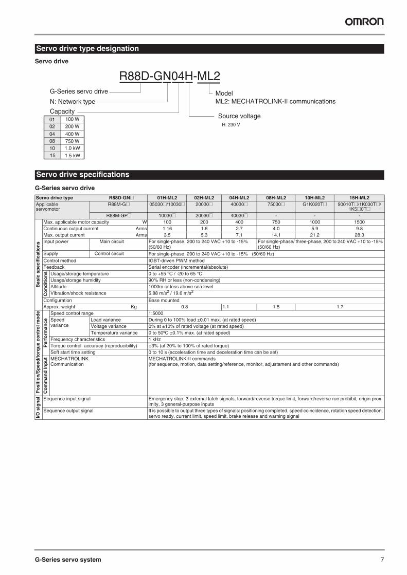
Servo drive
G-Series servo drive
Servo drive type designation
Servo drive specifications
Servo drive type R88D-GN@ 01H-ML2 02H-ML2 04H-ML2 08H-ML2 10H-ML2 15H-ML2Applicableservomotor
R88M-G@ 05030@/10030@ 20030@ 40030@ 75030@ G1K020T@ 90010T@/1K030T@/1K5@0T@
R88M-GP@ 10030@ 20030@ 40030@ - - -
Bas
ic s
pec
ific
atio
ns
Max. applicable motor capacity W 100 200 400 750 1000 1500Continuous output current Arms 1.16 1.6 2.7 4.0 5.9 9.8Max. output current Arms 3.5 5.3 7.1 14.1 21.2 28.3Input power Main circuit For single-phase, 200 to 240 VAC +10 to -15%
(50/60 Hz)For single-phase/ three-phase, 200 to 240 VAC +10 to -15% (50/60 Hz)
Supply Control circuit For single-phase, 200 to 240 VAC +10 to -15% (50/60 Hz) Control method IGBT-driven PWM methodFeedback Serial encoder (incremental/absolute)
Co
nd
itio
ns Usage/storage temperature 0 to +55 °C / -20 to 65 °C
Usage/storage humidity 90% RH or less (non-condensing)Altitude 1000m or less above sea levelVibration/shock resistance 5.88 m/s2 / 19.6 m/s2
Configuration Base mounted Approx. weight Kg 0.8 1.1 1.5 1.7
Po
siti
on
/Sp
eed
/to
rqu
e co
ntr
ol m
od
e
Per
form
ance
Speed control range 1:5000Speedvariance
Load variance During 0 to 100% load ±0.01 max. (at rated speed)Voltage variance 0% at ±10% of rated voltage (at rated speed)Temperature variance 0 to 50ºC ±0.1% max. (at rated speed)
Frequency characteristics 1 kHzTorque control accuracy (reproducibility) ±3% (at 20% to 100% of rated torque)Soft start time setting 0 to 10 s (acceleration time and deceleration time can be set)
Co
mm
and
Inp
ut MECHATROLINK
CommunicationMECHATROLINK-II commands(for sequence, motion, data setting/reference, monitor, adjustament and other commands)
I/O s
ign
al Sequence input signal Emergency stop, 3 external latch signals, forward/reverse torque limit, forward/reverse run prohibit, origin prox-imity, 3 general-purpose inputs
Sequence output signal It is possible to output three types of signals: positioning completed, speed coincidence, rotation speed detection, servo ready, current limit, speed limit, brake release and warning signal
100 W200 W
400 W750 W
0102
0408
1.5 kW151.0 kW10
G-Series servo drive
Capacity
ModelML2: MECHATROLINK-II communications
Source voltage H: 230 V
R88D-GN04H-ML2
N: Network type
8 AC servo systems
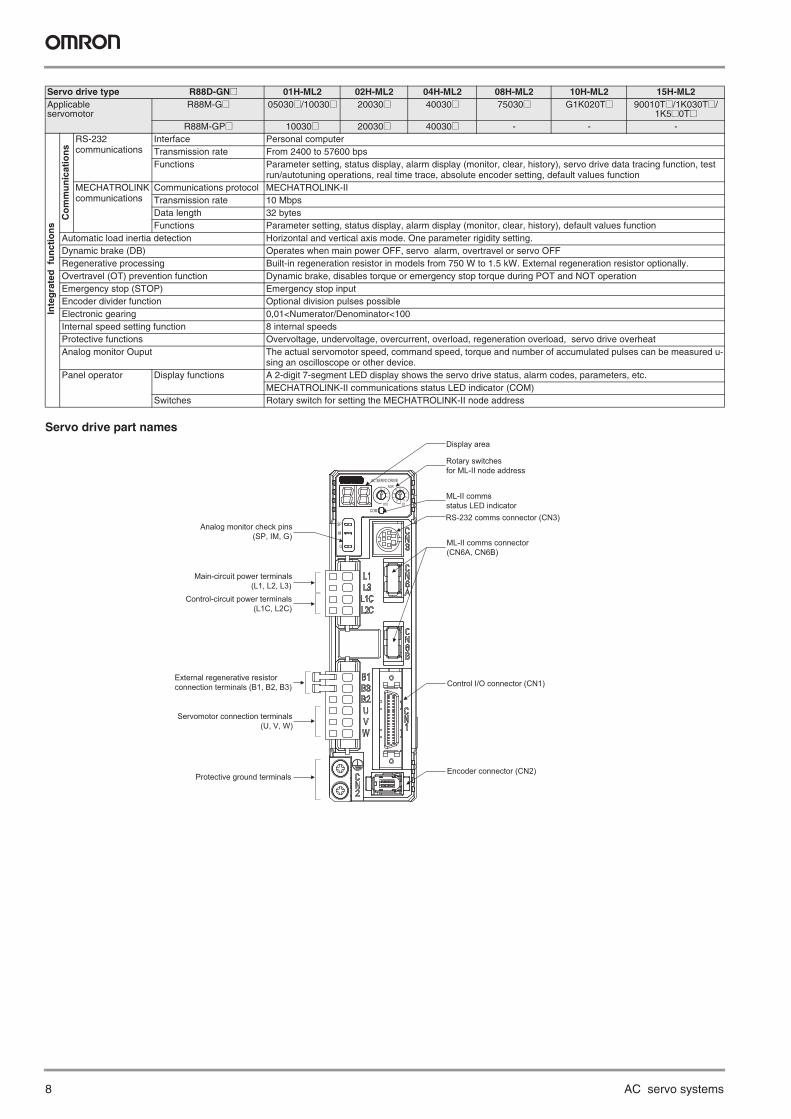
Servo drive part names
Inte
gra
ted
fu
nct
ion
s
Co
mm
un
icat
ion
s
RS-232communications
Interface Personal computerTransmission rate From 2400 to 57600 bpsFunctions Parameter setting, status display, alarm display (monitor, clear, history), servo drive data tracing function, test
run/autotuning operations, real time trace, absolute encoder setting, default values functionMECHATROLINK communications
Communications protocol MECHATROLINK-IITransmission rate 10 MbpsData length 32 bytesFunctions Parameter setting, status display, alarm display (monitor, clear, history), default values function
Automatic load inertia detection Horizontal and vertical axis mode. One parameter rigidity setting.Dynamic brake (DB) Operates when main power OFF, servo alarm, overtravel or servo OFFRegenerative processing Built-in regeneration resistor in models from 750 W to 1.5 kW. External regeneration resistor optionally.Overtravel (OT) prevention function Dynamic brake, disables torque or emergency stop torque during POT and NOT operationEmergency stop (STOP) Emergency stop inputEncoder divider function Optional division pulses possibleElectronic gearing 0,01<Numerator/Denominator<100Internal speed setting function 8 internal speedsProtective functions Overvoltage, undervoltage, overcurrent, overload, regeneration overload, servo drive overheatAnalog monitor Ouput The actual servomotor speed, command speed, torque and number of accumulated pulses can be measured u-
sing an oscilloscope or other device.Panel operator Display functions A 2-digit 7-segment LED display shows the servo drive status, alarm codes, parameters, etc.
MECHATROLINK-II communications status LED indicator (COM)Switches Rotary switch for setting the MECHATROLINK-II node address
Servo drive type R88D-GN@ 01H-ML2 02H-ML2 04H-ML2 08H-ML2 10H-ML2 15H-ML2Applicableservomotor
R88M-G@ 05030@/10030@ 20030@ 40030@ 75030@ G1K020T@ 90010T@/1K030T@/1K5@0T@
R88M-GP@ 10030@ 20030@ 40030@ - - -
Control I/O connector (CN1)
Encoder connector (CN2)
G
IM
SP
COMX10
32
10 ADRAC SERVO DRIVE
X1
678
9 0 1
23
45
Display area
Rotary switchesfor ML-II node address
ML-II commsstatus LED indicatorRS-232 comms connector (CN3)
ML-II comms connector (CN6A, CN6B)
Analog monitor check pins (SP, IM, G)
Main-circuit power terminals (L1, L2, L3)
Control-circuit power terminals (L1C, L2C)
External regenerative resistorconnection terminals (B1, B2, B3)
Servomotor connection terminals (U, V, W)
Protective ground terminals
G-Series servo system 9
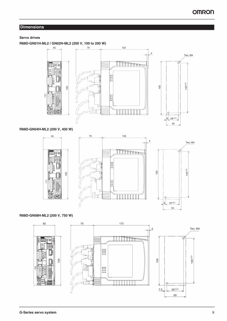
Servo drives
R88D-GN01H-ML2 / GN02H-ML2 (200 V, 100 to 200 W)
R88D-GN04H-ML2 (200 V, 400 W)
R88D-GN08H-ML2 (200 V, 750 W)
Dimensions
G
IM
SP
COM
X10
32
10ADR
AC SERVO DRIVER
X1
6
78
9 0 1
23
45
13270
4
150
40
28±0.56
40
Two, M4
140±
0.5
150
43±0.56
55
Two, M4
140±
0.5
150
13270
4
150
55
0
G
IM
SP
COM
X10
32
1ADR
AC SERVO DRIVER
X1
6
78
9 0 1
23
45
50±0.57.5
65
Two, M4
140±
0.5
150
0
G
IM
SP
COM
X10
32
1ADR
AC SERVO DRIVER
X1
6
78
9 0 1
23
45
17270
4
150
65
10 AC servo systems
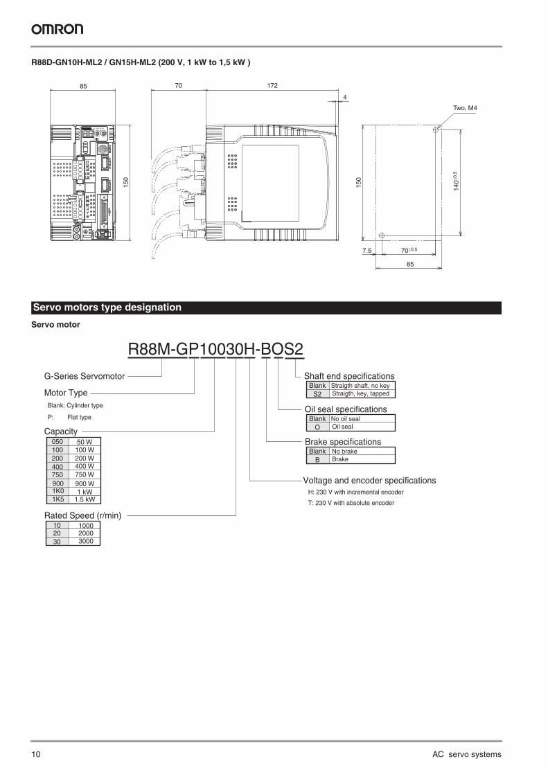
R88D-GN10H-ML2 / GN15H-ML2 (200 V, 1 kW to 1,5 kW )
Servo motor
70±0.57.5
85
Two, M4
140±
0.5
150
17270
4
150
85
0
G
IM
SP
COM
X10
32
1ADR
AC SERVO DRIVER
X1
6
78
9 0 1
23
45
Servo motors type designation
50 W100 W200 W400 W
050100200400
900 W900750 W750
G-Series Servomotor
Capacity
Shaft end specifications
Voltage and encoder specifications H: 230 V with incremental encoder
T: 230 V with absolute encoder
R88M-GP10030H-BOS2
Motor Type Blank: Cylinder type
P: Flat type
1K0 1 kW1K5 1.5 kW
Rated Speed (r/min)10002000 3000
102030
Straigth shaft, no keyBlankS2 Straigth, key, tapped
Oil seal specificationsNo oil sealBlank
O Oil seal
Brake specificationsNo brakeBlank
B Brake
G-Series servo system 11
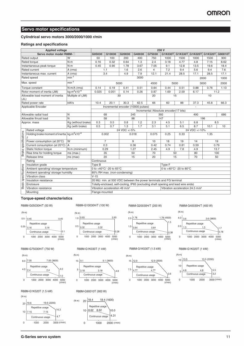
Cylindrical servo motors 3000/2000/1000 r/min
Ratings and specifications
Torque-speed charecteristics
Servo motor specifications
Applied voltage 230 VServo motor model R88M-@ G05030@ G10030@ G20030@ G40030@ G75030@ G1K030T G1K530T G1K020T G1K520T G90010T
Rated output W 50 100 200 400 750 1000 1500 1000 1500 900Rated torque N·m 0.16 0.32 0.64 1.3 2.4 3.18 4.77 4.8 7.15 8.62Instantaneous peak torque N·m 0.45 0.90 1.78 3.67 7.05 9.1 12.8 13.5 19.6 18.4Rated current A (rms) 1.1 1.6 2.6 4 7.2 9.4 5.6 9.4 7.6Instantaneous max. current A (rms) 3.4 4.9 7.9 12.1 21.4 28.5 17.1 28.5 17.1Rated speed min-1 3000 2000 1000
Max. speed min-15000 4500 5000 3000 2000
Torque constant N·m/A (rms) 0.14 0.19 0.41 0.51 0.64 0.44 0.51 0.88 0.76 1.13Rotor moment of inertia (JM) kg·m2x10-4 0.025 0.051 0.14 0.26 0.87 1.69 2.59 6.17 11.2Allowable load moment of inertia (JL)
Multiple of (JM) 30 20 15 10
Rated power rate kW/s 10.4 20.1 30.3 62.5 66 60 88 37.3 45.8 66.3Applicable Encoder Incremental encoder (10000 pulses) -
Incremental /Absolute encoder(17 bits)Allowable radial load N 68 245 392 490 686Allowable thrust load N 58 98 147 196Approx. mass Kg (without brake) 0.3 0.5 0.8 1.2 2.3 4.5 5.1 6.8 8.5
Kg (with brake) 0.5 0.7 1.3 1.7 3.1 5.1 6.5 8.7 10.1 10
Bra
ke s
peci
ficat
ions
Rated voltage 24 VDC +/-5% 24 VDC +/-10%Holding brake moment of inertia J
kg·m2x10-4 0.002 0.018 0.075 0.25 0.33 1.35
Power consumption (at 20°C) W 7 9 10 18 19 14 19Current consumption (at 20°C) A 0.3 0.36 0.42 0.74 0.81 0.59 0.79Static friction torque N.m (minimum) 0.29 1.27 2.45 4.9 7.8 4.9 13.7Rise time for holding torque ms (max.) 35 50 70 50 80 100Release time ms (max) 20 15 20 15 70 50
Bas
ic s
peci
ficat
ions
Rating ContinuousInsulation grade Type B Type FAmbient operating/ storage temperature 0 to +40°C/ -20 to 65°C 0 to +40°C/ -20 to 80°CAmbient operating/ storage humidity 85% RH max. (non-condensing)Vibration class V-15Insulation resistance 20 MΩ min. at 500 VDC between the power terminals and FG terminalEnclosure Totally-enclosed, self-cooling, IP65 (excluding shaft opening and lead wire ends)Vibration resistance Vibration acceleration 49 m/s² Vibration acceleration 24.5 m/s²Mounting Flange-mounted
0.25
0 1000 2000 3000 4000 5000
0.5 0.45
0.16 0.16
0.1
0.45
Repetitive usage
Continuous usage
(N·m)
(r/min)
R88M-G05030H/T (50 W)
0.5
0 1000 2000 3000 4000 5000
1.0 0.93
0.32 0.32
0.93
0.28
Repetitive usage
Continuous usage
(N·m)
(r/min)
R88M-G10030H/T (100 W)
1.0
0 1000 2000 3000 4000 5000
2.0 1.78
0.64 0.64
0.38
1.5
1.78 (4500)
Repetitive usage
Continuous usage
(N·m)
(r/min)
R88M-G20030H/T (200 W) R88M-G40030H/T (400 W)
R88M-G75030H/T (750 W) R88M-G1K030T (1 kW) R88M-G1K530T (1.5 kW)
2.0
0 1000 2000 3000 4000 5000
4.0 3.6
1.3 1.3 1.7
0.78
3.6 (3800)
Repetitive usage
Continuous usage
(N·m)
(r/min)
4.0
0 1000 2000 3000 4000 5000
8.0 7.05
2.4 2.4 4.0
1.0
7.05 (3600)
Repetitive usage
Continuous usage
(N·m)
(r/min)
5
0 1000 2000 3000 4000 5000
10 9.1
3.18 3.18 4.8
9.1 (3600)
Repetitive usage
Continuous usage
(N·m)
(r/min)
7.5
0 1000 2000 3000 4000 5000
15 12.9
4.77 4.773.6
12.9 (3500)
Repetitive usage
Continuous usage
(N·m)
(r/min)
R88M-G1K020T (1 kW)
R88M-G1K520T (1.5 kW)
0 1000 2000
5
10
15
3000
13.5
4.8 4.8 5.53.2
13.5 (2200)
Repetitive usage
Continuous usage
(N·m)
(r/min)
10
0
20
1000 2000 3000
19.6
14.3
4.7
7.15 7.15
19.6 (2200)
Repetitive usage
Continuous usage
(N·m)
(r/min)
10
0
20 18.4
10.0
4.31
8.62 8.62
1000 2000
18.4 (1600)
Repetitive usage
Continuous usage
(N·m)
(r/min)
R88M-G90010T (900 W)
12 AC servo systems
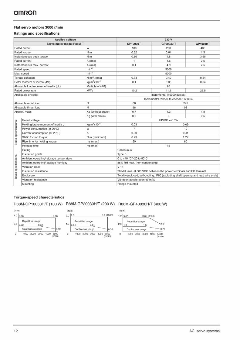
Flat servo motors 3000 r/min
Ratings and specifications
Torque-speed charecteristics
Applied voltage 230 V
Servo motor model R88M-@ GP10030@ GP20030@ GP40030@Rated output W 100 200 400
Rated torque N·m 0.32 0.64 1.3
Instantaneous peak torque N·m 0.86 1.8 3.65
Rated current A (rms) 1 1.6 2.5
Instantaneous max. current A (rms) 3.1 4.9 7.5
Rated speed min-1 3000
Max. speed min-1 5000
Torque constant N·m/A (rms) 0.34 0.42 0.54
Rotor moment of inertia (JM) kg·m2x10-4 0.1 0.35 0.64
Allowable load moment of inertia (JL) Multiple of (JM) 20
Rated power rate kW/s 10.2 11.5 25.5
Applicable encoder Incremental (10000 pulses)
Incremental /Absolute encoder(17 bits)
Allowable radial load N 68 245
Allowable thrust load N 58 98
Approx. mass Kg (without brake) 0.7 1.3 1.8
Kg (with brake) 0.9 2 2.5
Bra
ke s
peci
ficat
ions
Rated voltage 24VDC +/-10%
Holding brake moment of inertia J kg·m2x10-4 0.03 0.09
Power consumption (at 20°C) W 7 10
Current consumption (at 20°C) A 0.29 0.41
Static friction torque N.m (minimum) 0.29 1.27
Rise time for holding torque ms (max.) 50 60
Release time ms (max) 15
Bas
ic s
peci
ficat
ions
Rating Continuous
Insulation grade Type B
Ambient operating/ storage temperature 0 to +40 °C/ -20 to 80°C
Ambient operating/ storage humidity 85% RH max. (non-condensing)
Vibration class V-15
Insulation resistance 20 MΩ min. at 500 VDC between the power terminals and FG terminal
Enclosure Totally-enclosed, self-cooling, IP65 (excluding shaft opening and lead wire ends)
Vibration resistance Vibration acceleration 49 m/s2
Mounting Flange-mounted
0.5
0 1000 2000 3000 4000 5000
1.0 0.86
0.32 0.32
0.19
0.86
Repetitive usage
Continuous usage
(N·m)
(r/min)
R88M-GP10030H/T (100 W) R88M-GP20030H/T (200 W) R88M-GP40030H/T (400 W)
1.0
0 1000 2000 3000 4000 5000
2.0 1.8
0.64
0.38
0.64
1.8 (4500)
Repetitive usage
Continuous usage
(N·m)
(r/min)
2.0
0 1000 2000 3000 4000 5000
4.0 3.65
1.3 1.3 2.0
0.78
3.65 (3600)
Repetitive usage
Continuous usage
(N·m)
(r/min)
G-Series servo system 13
Servo motors
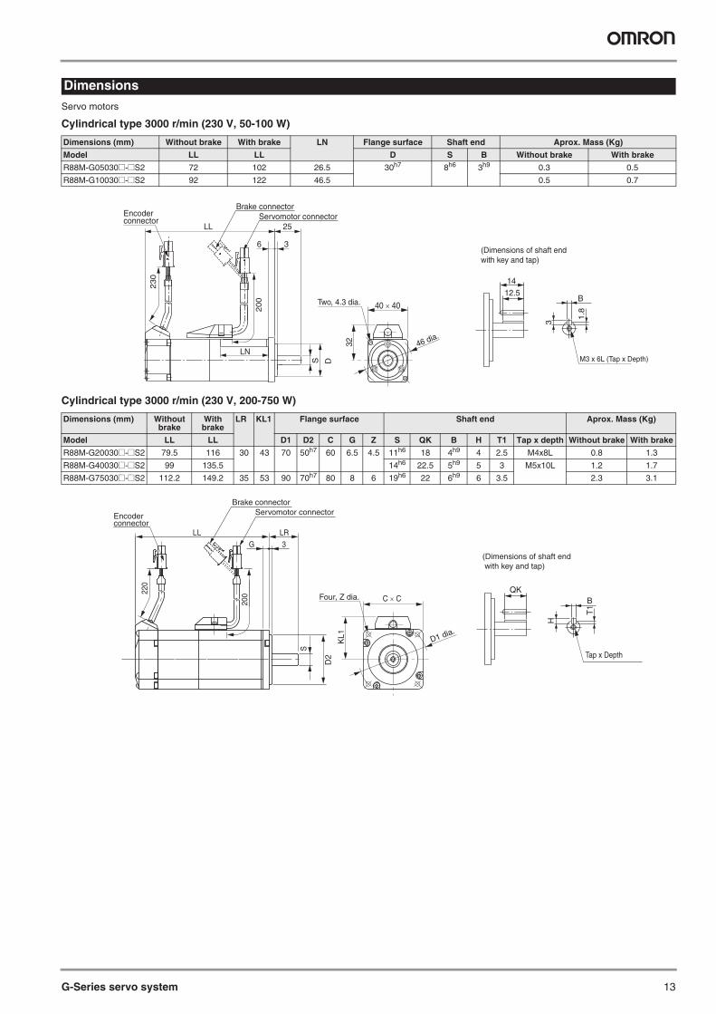
Cylindrical type 3000 r/min (230 V, 50-100 W)
Cylindrical type 3000 r/min (230 V, 200-750 W)
Dimensions
Dimensions (mm) Without brake With brake LN Flange surface Shaft end Aprox. Mass (Kg)
Model LL LL D S B Without brake With brake
R88M-G05030@-@S2 72 102 26.5 30h7 8h6 3h9 0.3 0.5
R88M-G10030@-@S2 92 122 46.5 0.5 0.7
Dimensions (mm) Without brake
With brake
LR KL1 Flange surface Shaft end Aprox. Mass (Kg)
Model LL LL D1 D2 C G Z S QK B H T1 Tap x depth Without brake With brake
R88M-G20030@-@S2 79.5 116 30 43 70 50h7 60 6.5 4.5 11h6 18 4h9 4 2.5 M4x8L 0.8 1.3
R88M-G40030@-@S2 99 135.5 14h6 22.5 5h9 5 3 M5x10L 1.2 1.7
R88M-G75030@-@S2 112.2 149.2 35 53 90 70h7 80 8 6 19h6 22 6h9 6 3.5 2.3 3.1
32
40 × 40
46 dia.
Two, 4.3 dia.
LL
LN
200
25
36
230
S D
Encoderconnector
Brake connectorServomotor connector
B12.5
M3 x 6L (Tap x Depth)
1.8
3
14
(Dimensions of shaft end with key and tap)
KL1
C × C
D1 dia.
Four, Z dia.
220
200
3G
LL LR
S
Brake connectorServomotor connectorEncoder
connector
D2
QK
Tap x Depth
BT
1
H(Dimensions of shaft end with key and tap)
14 AC servo systems
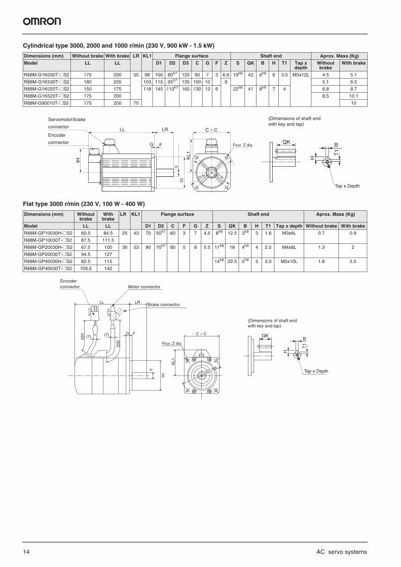
Cylindrical type 3000, 2000 and 1000 r/min (230 V, 900 kW - 1.5 kW)
Flat type 3000 r/min (230 V, 100 W - 400 W)
Dimensions (mm) Without brake With brake LR KL1 Flange surface Shaft end Aprox. Mass (Kg)
Model LL LL D1 D2 D3 C G F Z S QK B H T1 Tap x depth
Without brake
With brake
R88M-G1K030T-@S2 175 200 55 98 100 80h7 120 90 7 3 6.6 19h6 42 6h9 6 3.5 M5x12L 4.5 5.1
R88M-G1K530T-@S2 180 205 103 115 95h7 135 100 10 9 5.1 6.5
R88M-G1K020T-@S2 150 175 118 145 110h7 165 130 12 6 22h6 41 8h9 7 4 6.8 8.7
R88M-G1K520T-@S2 175 200 8.5 10.1
R88M-G90010T-@S2 175 200 70 10
Dimensions (mm) Without brake
With brake
LR KL1 Flange surface Shaft end Aprox. Mass (Kg)
Model LL LL D1 D2 C F G Z S QK B H T1 Tap x depth Without brake With brake
R88M-GP10030H-@S2 60.5 84.5 25 43 70 50h7 60 3 7 4.5 8h6 12.5 3h9 3 1.8 M3x6L 0.7 0.9
R88M-GP10030T-@S2 87.5 111.5
R88M-GP20030H-@S2 67.5 100 30 53 90 70h7 80 5 8 5.5 11h6 18 4h9 4 2.5 M4x8L 1.3 2
R88M-GP20030T-@S2 94.5 127
R88M-GP40030H-@S2 82.5 115 14h6 22.5 5h9 5 3.0 M5x10L 1.8 2.5
R88M-GP40030T-@S2 109.5 142
Encoder
connector
Servomotor/brake
connectorLL LR
G F
KL1
84
C × C
Four, Z dia.
D1 dia.D2
S
D3 dia.
QK B
T1
H
Tap x Depth
(Dimensions of shaft endwith key and tap)
LL LR
FG
200
220
KL1
C × C
Brake connector
Motor connector
(7) (7)
Encoderconnector
Four, Z dia.
D2
S D1 dia.
BQK
Tap x Depth
T1
H
(Dimensions of shaft endwith key and tap)
G-Series servo system 15
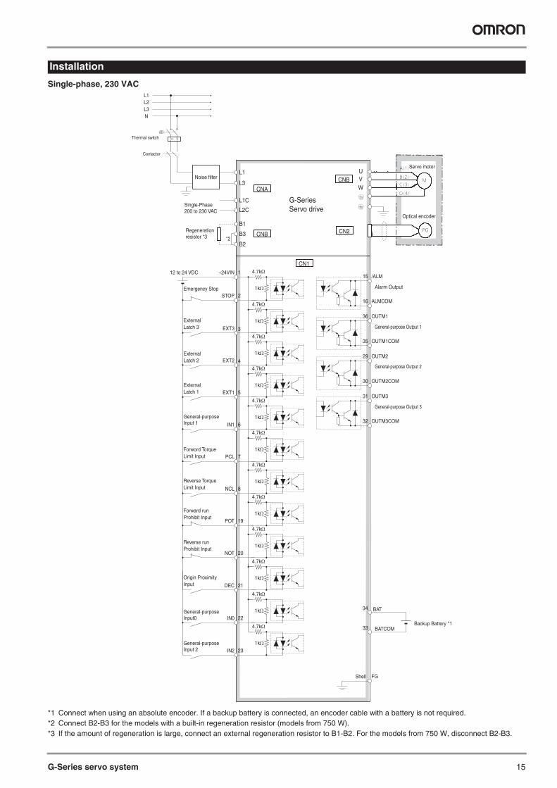
Single-phase, 230 VAC
*1 Connect when using an absolute encoder. If a backup battery is connected, an encoder cable with a battery is not required.*2 Connect B2-B3 for the models with a built-in regeneration resistor (models from 750 W).*3 If the amount of regeneration is large, connect an external regeneration resistor to B1-B2. For the models from 750 W, disconnect B2-B3.
Installation
Emergency Stop
/ALM
Alarm Output
ALMCOM
15
16
8NCL
7PCL
6IN1
5EXT1
4EXT2
3EXT3
2STOP
1+24VIN
Forword Torque Limit Input
General-purpose Input 1
External Latch 1
External Latch 2
External Latch 3
12 to 24 VDC
19POT
Forward run Prohibit Input
20NOT
21DEC
Origin ProximityInput
Shell FG
BAT
BATCOMBackup Battery *1
34
33
22IN0General-purpose Input0
23IN2General-purpose Input 2
4.7kΩ
1kΩ
4.7kΩ
1kΩ
4.7kΩ
1kΩ
4.7kΩ
1kΩ
4.7kΩ
1kΩ
4.7kΩ
1kΩ
4.7kΩ
1kΩ
4.7kΩ
1kΩ
4.7kΩ
1kΩ
4.7kΩ
1kΩ
4.7kΩ
1kΩ
4.7kΩ
1kΩ
OUTM1
General-purpose Output 1
OUTM1COM
36
35
OUTM2
General-purpose Output 2
OUTM2COM
29
30
OUTM3
General-purpose Output 3
OUTM3COM
31
32
Reverse Torque Limit Input
Reverse run Prohibit Input
G-SeriesServo drive
Optical encoder
Servo motor
CN1
CN2B3
B2
UVW
B1
L1
L3
L1C
L2C
Regeneration resistor *3
Noise filter
CNB
CNA
CNB
*2
Single-Phase 200 to 230 VAC
Contactor
L1L2L3N
Thermal switch
16 AC servo systems
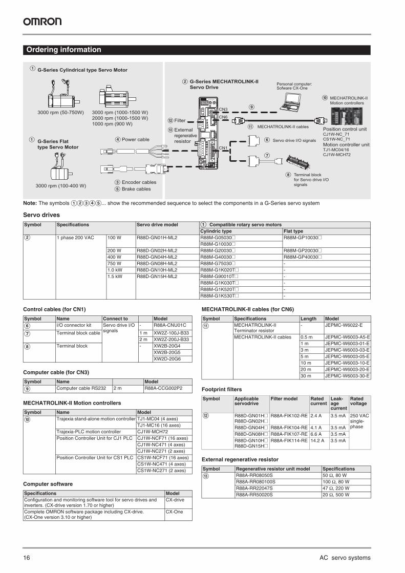
Ordering information
Note: The symbols ABCDE... show the recommended sequence to select the components in a G-Series servo system
Servo drives
Control cables (for CN1)
Computer cable (for CN3)
MECHATROLINK-II Motion controllers
Computer software
MECHATROLINK-II cables (for CN6)
Footprint filters
External regenerative resistor
Symbol Specifications Servo drive model A Compatible rotary servo motors Cylindric type Flat type
B 1 phase 200 VAC 100 W R88D-GN01H-ML2 R88M-G05030@ R88M-GP10030@R88M-G10030@
200 W R88D-GN02H-ML2 R88M-G20030@ R88M-GP20030@400 W R88D-GN04H-ML2 R88M-G40030@ R88M-GP40030@750 W R88D-GN08H-ML2 R88M-G75030@ -1.0 kW R88D-GN10H-ML2 R88M-G1K020T@ -1.5 kW R88D-GN15H-ML2 R88M-G90010T@ -
R88M-G1K030T@ -R88M-G1K520T@ -R88M-G1K530T@ -
3000 rpm (100-400 W)
A
A G-Series Flat type Servo Motor
CN6
CN1
L
G-Series MECHATROLINK-IIServo Drive
3000 rpm (1000-1500 W)2000 rpm (1000-1500 W)1000 rpm (900 W)
G
IM
SP
COMX10
32
10 ADRAC SERVO DRIVER
X1
678
9 0 1
234
5
Power cable
B
Encoder cablesC Brake cablesE
D
G-Series Cylindrical type Servo Motor
3000 rpm (50-750W)
F
G
Personal computer: Sofware CX-One
Terminal block for Servo drive I/O signals
Servo drive I/O signals
H
ICN3
J MECHATROLINK-II Motion controllers
Filter
Position control unitCJ1W-NC_71 CS1W-NC_71Motion controller unit TJ1-MC04/16CJ1W-MCH72
MECHATROLINK-II cables K M External
regenerativeresistor
Symbol Name Connect to Model
F I/O connector kit Servo drive I/O signals
- R88A-CNU01C
G Terminal block cable 1 m XW2Z-100J-B332 m XW2Z-200J-B33
H Terminal block - XW2B-20G4XW2B-20G5XW2D-20G6
Symbol Name Model
I Computer cable RS232 2 m R88A-CCG002P2
Symbol Name Model
J Trajexia stand-alone motion controller TJ1-MC04 (4 axes)TJ1-MC16 (16 axes)
Trajexia-PLC motion controller CJ1W-MCH72Position Controller Unit for CJ1 PLC CJ1W-NCF71 (16 axes)
CJ1W-NC471 (4 axes)CJ1W-NC271 (2 axes)
Position Controller Unit for CS1 PLC CS1W-NCF71 (16 axes)CS1W-NC471 (4 axes)CS1W-NC271 (2 axes)
Specifications ModelConfiguration and monitoring software tool for servo drives and inverters. (CX-drive version 1.70 or higher)
CX-drive
Complete OMRON software package including CX-drive. (CX-One version 3.10 or higher)
CX-One
Symbol Specifications Length Model
K MECHATROLINK-II Terminator resistor
- JEPMC-W6022-E
MECHATROLINK-II cables 0.5 m JEPMC-W6003-A5-E1 m JEPMC-W6003-01-E3 m JEPMC-W6003-03-E5 m JEPMC-W6003-05-E10 m JEPMC-W6003-10-E20 m JEPMC-W6003-20-E30 m JEPMC-W6003-30-E
Symbol Applicable servodrive
Filter model Rated current
Leak-age current
Rated voltage
L R88D-GN01H@R88D-GN02H@
R88A-FIK102-RE 2.4 A 3.5 mA 250 VAC single-phaseR88D-GN04H@ R88A-FIK104-RE 4.1 A 3.5 mA
R88D-GN08H@ R88A-FIK107-RE 6.6 A 3.5 mAR88D-GN10H@R88D-GN15H@
R88A-FIK114-RE 14.2 A 3.5 mA
Symbol Regenerative resistor unit model Specifications
M R88A-RR08050S 50 Ω, 80 WR88A-RR080100S 100 Ω, 80 WR88A-RR22047S 47 Ω, 220 WR88A-RR50020S 20 Ω, 500 W
G-Series servo system 17
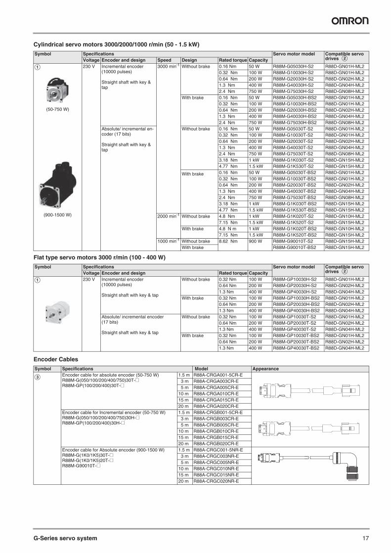
Cylindrical servo motors 3000/2000/1000 r/min (50 - 1.5 kW)
Flat type servo motors 3000 r/min (100 - 400 W)
Encoder Cables
Symbol Specifications Servo motor model Compatible servo drives BVoltage Encoder and design Speed Design Rated torque Capacity
A 230 V Incremental encoder(10000 pulses)
Straight shaft with key & tap
3000 min-1 Without brake 0.16 Nm 50 W R88M-G05030H-S2 R88D-GN01H-ML20.32 Nm 100 W R88M-G10030H-S2 R88D-GN01H-ML20.64 Nm 200 W R88M-G20030H-S2 R88D-GN02H-ML21.3 Nm 400 W R88M-G40030H-S2 R88D-GN04H-ML22.4 Nm 750 W R88M-G75030H-S2 R88D-GN08H-ML2
With brake 0.16 Nm 50 W R88M-G05030H-BS2 R88D-GN01H-ML20.32 Nm 100 W R88M-G10030H-BS2 R88D-GN01H-ML20.64 Nm 200 W R88M-G20030H-BS2 R88D-GN02H-ML21.3 Nm 400 W R88M-G40030H-BS2 R88D-GN04H-ML22.4 Nm 750 W R88M-G75030H-BS2 R88D-GN08H-ML2
Absolute/ incremental en-coder (17 bits)
Straight shaft with key & tap
Without brake 0.16 Nm 50 W R88M-G05030T-S2 R88D-GN01H-ML20.32 Nm 100 W R88M-G10030T-S2 R88D-GN01H-ML20.64 Nm 200 W R88M-G20030T-S2 R88D-GN02H-ML21.3 Nm 400 W R88M-G40030T-S2 R88D-GN04H-ML22.4 Nm 750 W R88M-G75030T-S2 R88D-GN08H-ML23.18 Nm 1 kW R88M-G1K030T-S2 R88D-GN15H-ML24.77 Nm 1.5 kW R88M-G1K530T-S2 R88D-GN15H-ML2
With brake 0.16 Nm 50 W R88M-G05030T-BS2 R88D-GN01H-ML20.32 Nm 100 W R88M-G10030T-BS2 R88D-GN01H-ML20.64 Nm 200 W R88M-G20030T-BS2 R88D-GN02H-ML21.3 Nm 400 W R88M-G40030T-BS2 R88D-GN04H-ML22.4 Nm 750 W R88M-G75030T-BS2 R88D-GN08H-ML23.18 Nm 1 kW R88M-G1K030T-BS2 R88D-GN15H-ML24.77 Nm 1.5 kW R88M-G1K530T-BS2 R88D-GN15H-ML2
2000 min-1 Without brake 4.8 Nm 1 kW R88M-G1K020T-S2 R88D-GN10H-ML27.15 Nm 1.5 kW R88M-G1K520T-S2 R88D-GN15H-ML2
With brake 4.8 N m 1 kW R88M-G1K020T-BS2 R88D-GN10H-ML27.15 Nm 1.5 kW R88M-G1K520T-BS2 R88D-GN15H-ML2
1000 min-1 Without brake 8.62 Nm 900 W R88M-G90010T-S2 R88D-GN15H-ML2With brake R88M-G90010T-BS2 R88D-GN15H-ML2
Symbol Specifications Servo motor model Compatible servo drives BVoltage Encoder and design Rated torque Capacity
A 230 V Incremental encoder(10000 pulses)
Straight shaft with key & tap
Without brake 0.32 Nm 100 W R88M-GP10030H-S2 R88D-GN01H-ML20.64 Nm 200 W R88M-GP20030H-S2 R88D-GN02H-ML21.3 Nm 400 W R88M-GP40030H-S2 R88D-GN04H-ML2
With brake 0.32 Nm 100 W R88M-GP10030H-BS2 R88D-GN01H-ML20.64 Nm 200 W R88M-GP20030H-BS2 R88D-GN02H-ML21.3 Nm 400 W R88M-GP40030H-BS2 R88D-GN04H-ML2
Absolute/ incremental encoder (17 bits)
Straight shaft with key & tap
Without brake 0.32 Nm 100 W R88M-GP10030T-S2 R88D-GN01H-ML20.64 Nm 200 W R88M-GP20030T-S2 R88D-GN02H-ML21.3 Nm 400 W R88M-GP40030T-S2 R88D-GN04H-ML2
With brake 0.32 Nm 100 W R88M-GP10030T-BS2 R88D-GN01H-ML20.64 Nm 200 W R88M-GP20030T-BS2 R88D-GN02H-ML21.3 Nm 400 W R88M-GP40030T-BS2 R88D-GN04H-ML2
Symbol Specifications Model Appearance
C Encoder cable for absolute encoder (50-750 W)R88M-G(050/100/200/400/750)30T-@R88M-GP(100/200/400)30T-@
1.5 m R88A-CRGA001-5CR-E3 m R88A-CRGA003CR-E5 m R88A-CRGA005CR-E
10 m R88A-CRGA010CR-E15 m R88A-CRGA015CR-E20 m R88A-CRGA020CR-E
Encoder cable for Incremental encoder (50-750 W)R88M-G(050/100/200/400/750)30H-@R88M-GP(100/200/400)30H-@
1.5 m R88A-CRGB001-5CR-E3 m R88A-CRGB003CR-E5 m R88A-CRGB005CR-E
10 m R88A-CRGB010CR-E15 m R88A-CRGB015CR-E20 m R88A-CRGB020CR-E
Encoder cable for Absolute encoder (900-1500 W)R88M-G(1K0/1K5)30T-@R88M-G(1K0/1K5)20T-@R88M-G90010T-@
1.5 m R88A-CRGC001-5NR-E3 m R88A-CRGC003NR-E5 m R88A-CRGC005NR-E
10 m R88A-CRGC010NR-E15 m R88A-CRGC015NR-E20 m R88A-CRGC020NR-E
(50-750 W)
(900-1500 W)
18 AC servo systems
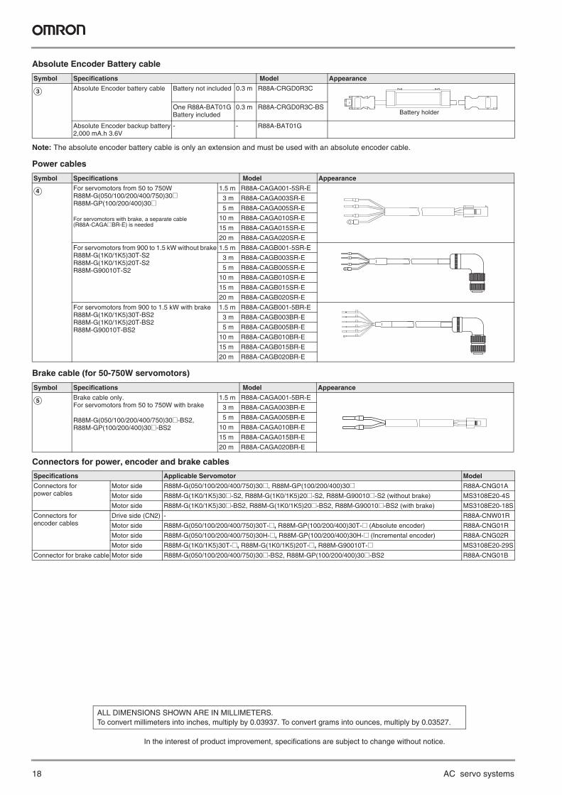
Absolute Encoder Battery cable
Note: The absolute encoder battery cable is only an extension and must be used with an absolute encoder cable.
Power cables
Brake cable (for 50-750W servomotors)
Connectors for power, encoder and brake cables
Symbol Specifications Model Appearance
C Absolute Encoder battery cable Battery not included 0.3 m R88A-CRGD0R3C
One R88A-BAT01G Battery included
0.3 m R88A-CRGD0R3C-BS
Absolute Encoder backup battery2,000 mA.h 3.6V
- - R88A-BAT01G
Symbol Specifications Model Appearance
D For servomotors from 50 to 750WR88M-G(050/100/200/400/750)30@R88M-GP(100/200/400)30@
For servomotors with brake, a separate cable (R88A-CAGA@BR-E) is needed
1.5 m R88A-CAGA001-5SR-E
3 m R88A-CAGA003SR-E
5 m R88A-CAGA005SR-E
10 m R88A-CAGA010SR-E
15 m R88A-CAGA015SR-E
20 m R88A-CAGA020SR-E
For servomotors from 900 to 1.5 kW without brakeR88M-G(1K0/1K5)30T-S2R88M-G(1K0/1K5)20T-S2R88M-G90010T-S2
1.5 m R88A-CAGB001-5SR-E
3 m R88A-CAGB003SR-E
5 m R88A-CAGB005SR-E
10 m R88A-CAGB010SR-E
15 m R88A-CAGB015SR-E
20 m R88A-CAGB020SR-E
For servomotors from 900 to 1.5 kW with brakeR88M-G(1K0/1K5)30T-BS2R88M-G(1K0/1K5)20T-BS2R88M-G90010T-BS2
1.5 m R88A-CAGB001-5BR-E
3 m R88A-CAGB003BR-E
5 m R88A-CAGB005BR-E
10 m R88A-CAGB010BR-E
15 m R88A-CAGB015BR-E
20 m R88A-CAGB020BR-E
Symbol Specifications Model Appearance
E Brake cable only. For servomotors from 50 to 750W with brake
R88M-G(050/100/200/400/750)30@-BS2, R88M-GP(100/200/400)30@-BS2
1.5 m R88A-CAGA001-5BR-E
3 m R88A-CAGA003BR-E
5 m R88A-CAGA005BR-E
10 m R88A-CAGA010BR-E
15 m R88A-CAGA015BR-E
20 m R88A-CAGA020BR-E
Battery holder
Specifications Applicable Servomotor Model
Connectors for power cables
Motor side R88M-G(050/100/200/400/750)30@, R88M-GP(100/200/400)30@ R88A-CNG01A
Motor side R88M-G(1K0/1K5)30@-S2, R88M-G(1K0/1K5)20@-S2, R88M-G90010@-S2 (without brake) MS3108E20-4S
Motor side R88M-G(1K0/1K5)30@-BS2, R88M-G(1K0/1K5)20@-BS2, R88M-G90010@-BS2 (with brake) MS3108E20-18S
Connectors for encoder cables
Drive side (CN2) - R88A-CNW01R
Motor side R88M-G(050/100/200/400/750)30T-@, R88M-GP(100/200/400)30T-@ (Absolute encoder) R88A-CNG01R
Motor side R88M-G(050/100/200/400/750)30H-@, R88M-GP(100/200/400)30H-@ (Incremental encoder) R88A-CNG02R
Motor side R88M-G(1K0/1K5)30T-@, R88M-G(1K0/1K5)20T-@, R88M-G90010T-@ MS3108E20-29S
Connector for brake cable Motor side R88M-G(050/100/200/400/750)30@-BS2, R88M-GP(100/200/400)30@-BS2 R88A-CNG01B
In the interest of product improvement, specifications are subject to change without notice.
ALL DIMENSIONS SHOWN ARE IN MILLIMETERS.To convert millimeters into inches, multiply by 0.03937. To convert grams into ounces, multiply by 0.03527.
KPP_G-Series_EN_INT01
Austria
Tel: +43 (0) 2236 377 800 www.industrial.omron.at
Belgium
Tel: +32 (0) 2 466 24 80 www.industrial.omron.be
Czech Republic
Tel: +420 234 602 602 www.industrial.omron.cz
Denmark
Tel: +45 43 44 00 11 www.industrial.omron.dk
Finland
Tel: +358 (0) 207 464 200www.industrial.omron.fi
France
Tel: +33 (0) 1 56 63 70 00www.industrial.omron.fr
Germany
Tel: +49 (0) 2173 680 00 www.industrial.omron.de
Hungary
Tel: +36 1 399 30 50 www.industrial.omron.hu
Italy
Tel: +39 02 326 81 www.industrial.omron.it
Netherlands
Tel: +31 (0) 23 568 11 00 www.industrial.omron.nl
Norway
Tel: +47 (0) 22 65 75 00 www.industrial.omron.no
Poland
Tel: +48 (0) 22 645 78 60 www.industrial.omron.pl
Portugal
Tel: +351 21 942 94 00 www.industrial.omron.pt
Russia
Tel: +7 495 648 94 50 www.industrial.omron.ru
South-Africa
Tel: +27 (0)11 579 2600 www.industrial.omron.co.za
Spain
Tel: +34 913 777 900 www.industrial.omron.es
Sweden
Tel: +46 (0) 8 632 35 00 www.industrial.omron.se
Switzerland
Tel: +41 (0) 41 748 13 13 www.industrial.omron.ch
Turkey
Tel: +90 216 474 00 40 www.industrial.omron.com.tr
United Kingdom
Tel: +44 (0) 870 752 08 61 www.industrial.omron.co.uk
More Omron representatives
www.industrial.omron.eu
Although we strive for perfection, Omron Europe BV and/or its subsidiary and affiliated companies do not warrant or make any representations regarding the correctness or completeness of the information described in this document. We reserve the right to make any changes at any time without prior notice.
OMRON EUROPE B.V. Wegalaan 67-69, NL-2132 JD, Hoofddorp, The Netherlands. Tel: +31 (0) 23 568 13 00 Fax: +31 (0) 23 568 13 88 www.industrial.omron.eu
Automation Systems
• Programmable logic controllers (PLC) • Human machine interfaces (HMI) • Remote I/O • Industrial PC’s • Software
Motion & Drives
• Motion controllers • Servo systems • Inverters
Control Components
• Temperature controllers • Power supplies • Timers • Counters • Programmable relays • Digital panel indicators • Electromechanical relays • Monitoring products • Solid-state relays • Limit switches • Pushbutton switches • Low voltage switch gear
Sensing & Safety
• Photoelectric sensors • Inductive sensors • Capacitive & pressure sensors • Cable connectors • Displacement & width-measuring sensors • Vision systems • Safety networks • Safety sensors • Safety units/relay units • Safety door/guard lock switches
BP_G-Series_EN+EN_INT.indd 2BP_G-Series_EN+EN_INT.indd 2 28.10.2009 09:08:4128.10.2009 09:08:41