Embed Size (px)
Citation preview

,-
"GE" rr. "L (.-'7', ~I ["""'IGI.": I 1\ ',,) 1.: I. '.,. I ",.:" [
--- --- - ,- '--,-- --,
\~ L J \ ••• ) IB(IJ a.lL~iDN
('I]):
G- J
I
ENGINE - Fan Hotor Assembly - Introduction of Spinner Cones, Sta~e 1Blade Spacer, and Blade RetaiIIC}"
1. PLANNING INFOH~IATION
A. Effcctivity
Stage 1 Fan Rotor Blade Spacer (PIN 9050M88GOI and PIN9050~190Gl)I),
Spinner Cone (piN 9010M~6G02 and PIN 9074M95GOl),
Insert (PIN 9049M93POl, PIN 9049M93P03, and PIN9049~193P04),
installed on CF6-6D Engines and stocked as Spares.
NOTE: The modification defined by this Service Bulletinwill be introduced in production 6n CF6-6D EnginesSiN 451-388 and up.
B. Reason
Experience indicates that the Hook on the aft side of theStage 1 Fan Rotor Blade dovetail may not provide sufficientblade ret'ention under adverse operating conditions. Ifthe hook should shear, axial movement of the blade mightresult.
Axial movement can be minimized by employing a retainerwhich will transmit the forward load of the blade to tileaft'side of the Fan RotOl' Disc.
A new Fiberglas-filled Nylon Spacer is provided to helpprevent wear between the Retainer and the bottom of theFan Rotor Disc Slot. It also improves sealing whichreduces air leal:ap;ethru the disc.
The new Spinner Cone keys with the fOl'wal'dends of thcRetainers to help assure correct positlonin~ of theRetaine/'s Ju/'ing a"sembly, It also helps maintain COI',"cetpositioning of the Retainers during operation,
C. Description •
This Service Bulletin provides instructions for replacinKthC' pl.('s •........n~ t hi r.t~ ...,f"'i~~.'ll (~{;:.-:)Sl'arCI'S (P '1\ !)()~(,':v-'Gnl OJ"PIN 9050.190G01) and thirty-eq~ht Inserts (PIN 9(l49~1!,j3P(lI,
~Iarch 20173Revision 2. September 21/73
(CF6-6) 72-396 ~Pap;e 1 of 12 D

"
GENERAL @ ELECTRIC
~'~~\:J~~~ElI:GI~E- Fan Hotol' Asseml)ly
,-
, , ( t [' • 1. • '. '
Ice:7 (;)1n,n n n n~?n f)"i... -: \.... •. ~ '; I .••• L...:;:;I L.. LJ U '..J- lnt)'odu<;('Oil01 Spillll<'"COllC'S,S(a~C' 11\l"d" SI':I,""I', :Inti Bl:,,!.' 1:"(,,i"I-'r
PIN 90,19\1931'U3,or I'll'.' 90,19:'19:;1'04)with thirty-ei,;ht (38)new Spacers (PiN 9136M72G01) and thirty-eight (38) Retain-ers (piN 9136.1541'u2). TIl" present Spinner COlle (piN9010M26G02 or piN 9074~95GUl) is reworked to piN 9136M33G02,or replaced by PIN 9l36M70G~l or PIN 9136M70G02,
D. Compliance
This is a Campaign Change.
It Is recommended that this Service Bulletin be accomplishedat the first opportunity but not later than the nexte'Xposure.
IE.
F.
Approva 1
Approved by FAA DER CHI-liB, September 20/73.
Manpower
An estimated 3.0 man-hours are required per engine toaccomplish this Service Bu11etin. If Trim Balance isrequired, an additional 4.5 man-hours per engine arerequired to accomplish this Service Bulletin.
A Labor Credit Allowance will be granted for each engineactually accomplished per the effectivity of this ServiceBulletin. To obtain this Labor Credi t Allowance, submi ta Warranty Claim to:
General Electric CompanyCommercial Engine DivisionCF6 Warranty AdministrationAlai1 Zone N62Evcnd:tle, Ohio 4521~, U.S.A.
Telephone: Cincinnati, Ohio 513-2<13-3218 orDial Corom 8-332-3218
G. Material
The material required to accomplish this Service Bullet{n,)"C'ff'l"C'nC'('d in I"::r:l~~l':1!1h~.A. ":11(,1'i~1 RC"f"'l'til"C"TIH'n1-s. isilll.t1ally <l\'ailablL' 011 an all.u'L.'.ll-~<.r-G"as-rs-fl7()Jrl-ll1l..'" EubillCManufacturer. Send a Charge Purcllasc Order to:
(CF6-6) 72-396Par:e 2 of 12
~larch 20/73Revision 2, September 21/73

GENERAL@:.7;)ELECTRIC IeIF' I~"",.Ir.,~'l, n" ,'-.~ '7 0 ce, rl
l,."', PI, n n n n ~ ~ n ~ ~••.~ • '-"'........ ~ • . / ' .....__• -' L..::J l J L ."] LJ ~. .J ... .:
E\'GI.!'E _ Fan Rotor As",'mbly - Intl'ocluctionof Spinnt'l'Cones, Stag" 1nJac1t, Sr;;c('l'. :1.!HI Dl:1dt) I:l'tainpl"
} . (1..:011', '(1)
General Electric CompallYCommercial Engine DivisionCommercial Engine Spare PartsMail Zone B69Evendale, Ohio 45215, U.S.A,Telephone: Cincinnati, Ohio 513-243-4367 or
Dial Comm 8-332-4367
A Parts Credit Allowance will be granted in accurdanct'with the Campaign Change,barranty. To obtain this PartsCredit Allowance, submit a Warranty Claim to the officereferenced in paragraph l.F, ~lnnpo\\'er,ahove.
H. ToolingLocally-manufacture Protective Shield per Figure 3.
I. Weight and BalanceAccomplishment of this Service Bulletin results in aweight increase of 10.4 Ibs. at Engine Station 155.
J. ReferencesCF6,-6 Maintenance ~lanual, GEK 9265.
K. Previous ModificationsCF6-6D Service Bulletin (CF6-6) 72-108, "Stage 1 Insert".
CF6-6D Service Bulletin (CF6-6) 72-267, "ReplacementSpillnel'CO\'Cl',p/l' 9()7,l~,10,lP()I".CF6-6D Service Bulletin (CF6-6) 72-288, "ReplacementSpinner Cono Assembly, PIN 9U7'DI95GOl".
•
March 20/73Revision I, April 13/73
(CF6-6) 72-396page30fI2,',/
(~

G f: .• E " , l ("",, ' r. 'f nl CL,;~~.UI\ \i!.iJlo-!... ... ..,
fPi r,"lII .., -..l P\:, , '3 D' \' 17 I ' " I ',.
. . , . • , It,.",] .• ~\ '0. .••. i.i.)l 1
• Et;GINE - Fan Rotor Assembly - Introducli"ll of SpillllurCones, Stage 1Blade Spacer, and Blade Retainer
THIS PAGE IS INTENTIONALLY BLANK
•
)
(CF6-6) 72-396Page 4 of 12
Ma,'ch 20/73Revision 1, April 13/7:1
.'1
GENERAL @ ELECTRICr:"'\n r n ~ rc.a ~ n r- n, "
( . Li •. \,
E'iGIl\E- Fall nolol' Assl'mbly - IntJ'odllction01 SI,illllCI'C0I10,.;, Sla~(' Inladt:> ~':P:l("('l'. :.l~l. nl;l{~f~' l~('l;lill('l"
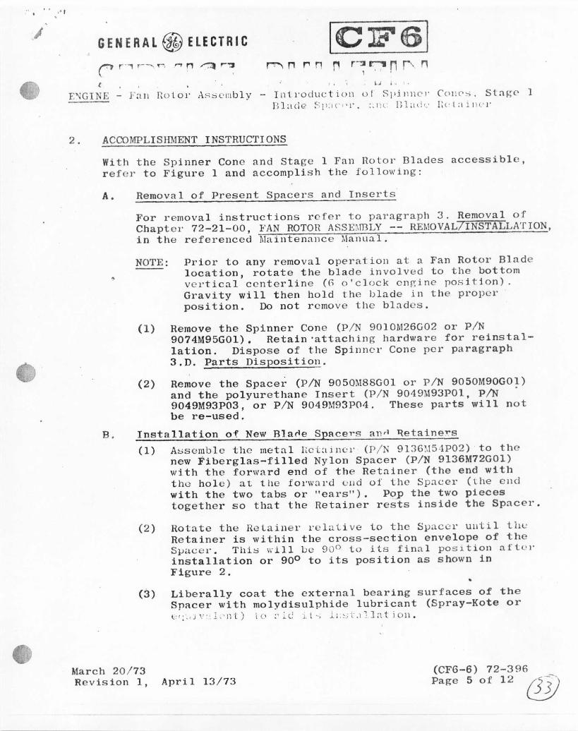
2. ACCOMPLISI~IENT INSTRUCTIONSWith the Spinner Cone and Stage I Fan Rolor Blades accessible,refer to Figure I and accomplish tIle following:
A. Removal of Present Spacers and InsertsFor removal instructions refer to paragrapll 3, Removal ofChapter 72-21-00, FAN ROTOR ASSEjffiLY-- RE~IOVAL7INSTALLATroN,in the referenced Maintenallce Mallllal.
NOTE: Prior to any removal operation at a Fan Rotor Bladelocation, rotate the blade involved to the bottomvertical centerline (G o'clock enRine position)"Gravity will then hold the blade in the properposition. Do not remove the blades.
(1) Remove the Spinner Cone (PiN 9010M26G02 or piN9074M95GOI). Retain 'attaching hardware for reinstal-lation. Dispose of the Spilinel'Cone per paragraph3.D. Parts Disposition.
(2) Remove the Spacer (PIN 9050M88GOI or piN 9050M90GOI)and the polyurethane Insert (PIN 904911931'01,PIN "9049M93p03, or PIN 904911931'04, These parts will notbe re-used.
B. Installation of New B]a~e Spacers an~ ~etainers(1) Assemble the metal I,eLa1nCI' (piN 9136~154P02) to the
new Fiberglas-filled Nylon Spacer (PIN 9136M72GOI)with the forward end of the Retainer (the end withthe hole) at the f01'l\'al'd'-'udof the Spacer (lhe cudwith the two tabs or "ears"). Pop the two piecestogether so that the Retainer rests inside the Spacer.
(2) Rotate the l(eLaiuel"relative to the SllaCe)'until tlll:Retainer is within the cross-section envelope of theSvaccr• Tllis will Le 900 to its final position aftol'installation or 900 to its position as shown inFigure 2.
•surfaces of the(Spray-Kate or
(3)
March 20/73Revision I,
Liberally coat the external bearingSpacer with molydisulphide lubricant(:';'.,j'.":1,'nt) IU :'l.I;.: it-; iJ.~_;t.11]:ltioll.
April 13/73(CFG-6) 72-396Page 5 of 12 ~

G'ENE R A l rt1;J El E CT RIC [CJF6]BUlRJEu~N . ,
ENGINE - Fan Rotor Assembly - Introduction of Spinner Cones, Stage 1Blade Spacer, and Blade Retainer
! .• ,,-- .' .'
(4) Wiih lhe Stal'e I }an Hot,,,,IHade lllstallcd and at the6 o'clock en~ine position of the Stage 1 Fan RotorDisc, insert the aft elld of the Spacer and RetainerAssembly (tabs or "ears" forward :llldpointin~ down)into the forward end of tllo Stage 1 Rotor Disc dove-tail slot between the inboard end of the Fan RotorBlnde dovetail and the inboard surface or "bottom" ofthe Rotor Disc dovetail slot.
(5) Usin~ a plastic 01' raw-hide hammer, carefully drivethe Spacer and Retainer assembly approximately half-way into the dovetail slot.
(6) Asscmhle the 10cally-manufactul'cd Protective Shi(,ldto the assembly so that the slot slips over the shankof the Retainer between the aft side of the ForwardHead of the Retainer and the forward end of theSpacer. The purpose of this shield is to protect theforward face of the Stage 1 Disc and forward edge ofthe dovetail slot. Refer to Figure 3.
(7) Hold the Protective Shield in position and, using aplastic or raw-hide hammer, carefully drive theSpacer and Retainer assembly in (aft) until the Pro-tective Shield bottoms against the forward face ofthe Stage 1 Fan Rotor Disc and the Fan Rotor BladeDovetail. Remove the Protective Shield.
CAUTION: USE CARE IN DHI\'n;G TilE ASSEMBLY TO AVOIDDAMAGE TO TilE FORWARD EDGE OF THE ROTORDISC SLOT.
(8) Carefully tap the Spacer and Retainer assembly untilthe aft face of the Forwal'd Ilead of the Retainer11':.11~ c:::-: :lg:-:. ~ l1:-;t the fOI'W~ll'd [:1('(": of the Fan 1~ntorBlade Dove tai 1.
(9) Rotate the Retainer so that the hole in the forwardend in radially outboard as shown in Figure 2, Thisis 90 from its position during insertion into thedovetail slot. The forward end or head will thencover the forward end of tile Fan Rotor Blade dovetailwhi 1•... the nft ('no cn~:--"'~c: lV"'!1inrf t11f' Fnn nn1ol" Disc10 1. .. Jl' 1'1-('~'-'~.l liiC J~ ;, ' •• \J\'~II~~ fOl"W;lld.
(CF6-6) 72<{96Page 6 of 12
March 20/73Revision 1, April 13/73

-, .GENERAL ~~ ELECTRIC
ENGINE - Fan notor Assembly - Introduotion of Spinm'l' Cones, Star:c 1Dlnde Spacol', and Blnde Relain.!"
2, B. (9) (Cont'd)'l'\:'~ r(, ....:~,l'd ('nd of 1Itt' nj.t:lin('t' should hel' 11ili:,., ct:~lhl:I!'d "jll1i:1 :..•() ul :1 1':1U1:1J lin('to pruvont intcl'fel'cncewi til till'rewol'kedSpinner Cone,
I
(10) Check the forward edges of the dovetail slots in theFan notor Disc for nicks. In the event that the edgeshould be nicked, remove the RetaineJ' and Spacer usingthe reful'enced Retainer Extractor, Dlend out the nickwith emcry clotlJ rubbing in a circumfeJ'ential direc-tion, Reinstall the Retainer and Spacer per paragraphs
, 2 .0. (4) t h I'U 2,0, (9). aho ve .
C. Installntion of the New or Reworked Spinner ConeInstall Spinner Cone (piN 9136M33G02 or piN 9136M70GOI orpiN 9136M70G02) per paragraph 4, Illstallntion of r.hapteJ'72-21-00, FAN ROTOR ASSDlBLY -- RE~IOVAL!INS'fALLATION. inthe referenced Maintenance Manual. Use the attachinghardware previously removed.NOTE; Engine vibration should be checked after assembly.
If necessary, Trim Balance the Fan Rotor Assemblyper paragraph 4.1. of Chapter 72-00-00, ADJUSTMENT/TEST, in the referenced Maintenance Manual .
•
March 20/73Revision 1, April 13/73
(CF6-G) 72-396Page 7 of 12

GENERAL (jJ;) ELECTRIC ICJF61'~~~,~1~~~ ~~_~r~~J~1T~~
Et:GT]I;L - Fall I;u!ul' A"Sl'lHU1y - Tntroducl lOll of Sp1l1l1l'I' COll(,5, Sta~(> 1Bladt' S:':!l"'l", "llli Blad,' Ill-lainer
')-ST'\GE I1l0TOH BLAlJE~ _. (no IiOT Ilnl0VE)
~- MIll-SPA:; SHIlOlJD
110 ALL IlEPLACING WITI!TIlE BLADE AT no' CLOCK
NOTE:
SP! ,:-OF.1l COVEll
STAGE 1 IlOTOIl])] SC PLATFOlll1
SPACEIl (3/l) )PIN 905ml/l/lGOl )~
PIN 90~~~190GOl U~ ._IHEPLACI:~D fly ~-'-""--*=-..~.'l. (,;;.~~,I_/.P/N 9~~~rol72GOl ~~, '_'I ~~>:flR.ETAlNEH (:18) ~ ( ~
INSEilT (3/l)- __ .L.. ,~., ':,' c/" '.1PIN 9l:J6M:>1P02 -.---- I ""~
PIN 9049M93POl/p03/p01 ~I~i"5C wt{:" , - " .h
SPI NNEil CONE (l) (DELETED) ~ ~PIN 901OM2GG02 ~/ (~;"'".,p SEAL SEIlIlATIONS
Oil I ~'1( ,-'PIN 9074M95GOl /' ~'! . , .HEPLACEJJ BY . ;--:"
PIN 91g~r'U:IG02! ,_ IPIN 9136M70GOl " BALA:-OCE ~~\ \
OR _-;', \' ,,',WEIGHT7\.,. ) \. •PIN 91 :H,~I'llIG021 ':\ ~' ,(' " ' \\, .ti\ \\ ,,'G,~
,\.,( ~~~g:;:lISC:- ;\ •. , . \\ ~'~
.J ....._" -"" ''7\' '~ -----"-~~~ -- "~ -;~-~,:-=--.-- .....•_,:•.~.......---,
~ ' u~ \J ~ __ .4f!/.~M/ , ...---,"<-~STAGE 2 HOTOIl DISC 'lC\\!~.~~
•Figure 1
Fan notl))" ASSC'lI1hl y
(eF6-6) 72-396Page 8 of 12
March 20/73Revision I, April 13/73

,. . ..
GENERAL @:.M elECTRIC [elF .~I~~c-~ [L~~rE1TD~
ENGINE- Fan !lotor Assembly - Introduction of Spj 111"'1' Cones, Stag-e 1DJ:-'.<!(~ ~P:1C('1', :llHl 13] :-"tiC) fl.:.,tainC'l.
SPINNElt CUNE
r+-L'.'l FOItI~AIU) LOOKING AFT
CENTERLINEO'CLOCK)
oRETAINERPIN 9136M54PO~
-i\C200~MOF FAN HarOR (6
o
STAGE 1 FAN ROTOH BLADEA'r {; O'CLOCK POSITION
o
ST,\GE 1 HarOR DI:iC
~M
IDISC
RETAINEIiPIN 91JGM54P02WITHINSPACEHPIN 9l:!GM72GOl
\:
STAGE I FANROTOR BLADE(AT (; O'CLOCK)
FWD I)
SECfION M-M
Figure 2Spacer and Retainer Installation
March 20/73Revision 1, April 1~/7~
(CFli-6) 72-396Page 9 of 12

.' .GENERAL (if:J ELECTRIC ICJF6/
fa~lH!Jt.[Ei~MENGINE - Fan Rotor Assembly - Illtroduct ion of Spinncl' Cone,,;, Stage I
nbd" Sp~cel', anc1 nInd,' RptninC'I'
----- .. _----- ._0-
O.:l IL\IJIl'S(I:EF)
O.22[)(1.173
~ .1.05
1----- O.9"
LOCALLY - MANUFACTl'HE"
J.1
i
--I0.55
==~_LlIATEHI'\L: STEEL SHEET
~():.1I!\.\J. TlIICL\T:-:~O.(I:{" (0.:-- :.::,1)
Figu re 3Protective Shield for Spacerand Retainer Installation •
(CF6-6) "12-396Page 10 of 12 March 20/73
Revision 1, April 13/73

GENERAL@ELECTRIC ICJF61:---~",~'!r ~ ~ PIn~nn ~!i~8'~
ENGINE - Fall Hotor AS",vllloly- JIIL1'ocilletjailuJ ~I'illlll'l'COI\PS, Stagp 1Blade Spacer, and Blade Retainer
3. MATERIAL INFORMATION
A. Material RequirementsThe following material is required per engine to accomplishThis Service Bulletin:
LeadUnit Pkg. Time
Part Number Qty. Price Key Word Qty. (Days)
9136M33G02 (1) NONPROV Spinner Cone (1)or
• 9136M70GOI (1) NONPROV Spinner Cone (1)or
9136M70G02 (1) $ 2600.00 Spinner Cone (1) 909136~154P02 (38) 78.00 Blade Retainer (1) 609136M72GOI (38) 10.00 Blade Spacer (1) 60
~: Price information is furnished solely for SpareParts Provisioning and Planning purposes.
B. Configuration Chart
Qtyl Qtyl Chng.New Part No. ~ Key Word Old Part No. Enet Operation Code
9690M04 X Engine Assembly 9690M04 X --------9136M33G02 (1) Cone, Spinner 9010M26G02 (1) Reworked 3
or or9136M70G02 (1) Cone. Spinner 9074M95GOI (1) Reworked 3
or or9136~170GO1 (1) Cone, Spinner 9074:,195GOI (1) Rcplaeed 3
or or9136M70G02 (1) Cone, Spinner 9136M70GOI (1) Replaced :191:1 (j :,1:;1P0~ (:1R) Retainer, Blade ---------- Aclded 09136M72GOI (3H) Spacer, 13lade 905U:,itlGGOI(3~) i~('plac0d "..
or9050:,lClUGUl(3H) R0plnccd 3
---------- Insert 9049M93P04 (38) Deleted
NOTE: Any new Spinner Cone may be used to replabe anyold Spinner Cone.
March 20173n"" i "j on 1, API' i 1 1::1/73
(CF6-6) 72-:196Page 11 of 12
/" -(D

.,j .' ••••,•• GENERAL @ ELECTRIC
, . leFta/~~J,~,~J~l1~~
~NGrNE - Fnn Hotor Assembly - Int"oduction or Spinncl' ConC's, Stal':c1BOLo,> Sl'::."r ~'. :l:'d nJ:ltlC r.C'~~I:Il"}'
3. (Cont'd)
C. Interchan~Dability
Old and new parts are not physically interchan~enbleexcept in complete sets.
Functional interchangeability is affected in that the newconfiguration has an additional blade retention feature .
...D. Parts Disposition
(1) Terminate (scrap) the deleted Inserts (PiN D049M93POl,PIN 9049M93P03, and piN 9049MD3P04) in the presenceof a GE Representative.
(2) Terminate (scrap) the replaced Spacers (PiN 9050M88GOlor PIN 9050M90G01) in the presence of a GE Represent-ative.
(3) Return reworkable Spinner Cones (PiN 90l0M26G02 orPIN 9074M95G01) to:
General Electric Company336 Woodward Road, SoutheastAlbuquerque, New Mexico 87102, U.S.A.
Attn: Fred Lopez
•
(CF6-6) 72-396Pa~e 12 of 12
March 20/73Revision 1, April 13/73