Embed Size (px)
Citation preview

IV
2. To: (Receiving Organization)
Characterization Engineering
5. Proj./Pmg./Dspt.K".: Characterization
49
3. From: (Originating Organization)
Equipment Engineering N/A ~ 7. Purcham Order No.: 6. Design AuthoritylDeslgn AgenVCog. Engr.:
N/A G. P. Janicek 9. Equip./Component No.:
4. Related EDT No.:
8. Originator Remarks:
This document is the Design Review Report for modifications to the Foot Clamp. It is being routed for review and approval.
~
11. Receiver Remarks: 11A. Design Baseline Document? @ Yes 0 No
(L) Date (M) MSlN
BD-7400-172-2 (1011)7) 00-7400-172-1
N/A 10. s y s ~ ~ @ s , / ~ a c i l i t :
N/A 12. Major Aum. Dwg. No.:
N/A 13. PermiVPennit Application No.:

RPP-5628, Rev. 0
Formal Design Review Foot Clamp Modification
Timothy C. Otmn CHZM Hill, Hanford Group, Inc. Richland, WA QQ352 HeL-IYaV7 U.S. Department of Energy Contract D E - A C 0 6 T , A r ,
OrgCode: 74700 Charge Code: 102206 B&R Code: EW3130000 Total Pages: 20
8 EDTIECN: 62686 uc: 2000
Key Words: Design Review, Foot Clamp
Abstract: This report documents the Design Review performed for the foot clamp modification. design, identifies the documents that were reviewed, the scope of the review and the members of the review team.
The report documents the acceptability of the
TRADEMARK DISCLAIMER R.hmnm hemin to any apeclik ccinnnrdal product, process, or wnrio by tmdr name. trndwrk, nunuhdunr, or otherwise, doas not namBMrliy mnrtitute or imply itr rndommrnt mcomnnndltion, or favoring by Vu Unwed States Oanrnmnt or any agency themof or Its oontndon or subcontncton.
Printed in Vu Unwed States ofkmia. To o b l n copler ofthir doarnwnt, mbd: Docurrmnl Control Sawkas. P.O. Box 850, Malbtop rmo8. Richland WA 99362. Phom (509) 372-2420; Fu (509) 376-4989.
t
I
Approved For Public Release

RPP-5628 Rev. 0
FORMAL DESIGN REVIEW FOOT CLAMP MODIFICATION
Timothy C. Oten
January 18,2000

RPP-5628 Revision 0
RPP-5628 FORMAL DESIGN REVIEW
FOOT CLAMP 'MODIFICATION
1.0 SCOPE
1.1 Overview
This report documents the formal design review of the foot clamp assembly for use with the Rotary Mode Core Sample (RMCS) trucks. The foot clamp assembly was originally designed for use with the Push Mode Sample (PMS) trucks, which are classified as General Service. The purpose of this design review was to determine whether the PMS foot clamp design is suitable for use on the RMCS trucks, which is a Safety Class application. The intent is to fabricate and test the RMCS and PMS foot clamp assemblies to satisfy Safety Class requirements so that they can be used in either application.
1.2 Foot Clamp Design
The foot clamp is designed to hold the drill string and prevent it from falling into the tank when the shielded receiver, quill rod or drill string hoist is disconnected, or in the event of a mechanical failure. The foot clamp assembly is made up of two pneumatically actuated pistons, a toggle style isolation valve and a three way isolation valve, a pressure gauge, a structural frame and miscellaneous tubing, nuts, bolts and fittings. The pistons are spring actuated to close and require air pressure to open; they fail closed on loss of air. The pistons are located opposite each other in the h e and extend toward each other to effectively clamp the drill string between them. Serrated jaws are attached at the end of each piston to ensure that the drill string does not slip when force is applied through the piston. The two valves are installed in series in the air supply line to the actuator to ensure that the foot clamp is not inadvertently opened. The foot clamp is designed for use with 2 '/2" fluted or 2 '/411 non-fluted drill string.
1.3 Documents Reviewed
The following documents were reviewed:
ECN 65561 1, dated 10/22/99. Modifications to PMS Foot Clamp Assembly. Site Fabrication Services Work Package. Testing results for foot clamp units 1,2 and 3, Work Order 2H9903622R. Foot Clamp Compliance Matrix. H-2-690138, Sheet 1 of 6, Rev. 0, Footclamp Assembly. H-2-690138, Sheet 2 of 6, Rev. 0, Footclamp Assembly. H-2-690138, Sheet 3 of 6, Rev. 0, Footclamp Details. H-2-690138, Sheet 4 of 6, Rev. 0, Footclamp Details. H-2-690138, Sheet 5 of 6, Rev. 0, Footclamp Details. H-2-690138, Sheet 6 of 6, Rev. 0, Footclamp Details.

IVP-5628 Revision 0
2.0 SUMMARY
The formal design review identified a number of comments to be incorporated into the design of the foot clamp. Based on a review of the final ECN (ECN 655621), there are no outstanding action items. The design review is complete and the foot clamp design is acceptable for the RMCS safety class application.
3.0 DOCUMENTATION
3.1 Design Review Checklist
A design review checklist was prepared to document the overall assessment of the foot clamp design. The checklist addresses major design considerations rather than individual requirements. The checklist is attached as Appendix A of this report.
3.2 Design Review Committee
The design review committee was selected to provide an independent assessment and review of the foot clamp design. Members were selected by the chairman with the concurrence. of their respective managers. Members are listed below:
0 Chairman: Timothy C. Oten 0 Design Authority: George P. Janicek 0 Cognizant Engineer: Troy R. Farris 0 Quality Assurance: Michael L. McElroy 0 Quality Assurance.: John J. Verderber 0 Safety: Cary D. Jackson 0 Engineering: Henry F. Shumake, Jr. 0 Engineering: Galen W. Wilson
33 Meeting Minutes
Meeting minutes from the design review were prepared and are included in Appendix B.
3.4 Other Documents
The compliance matrix and a portion of the Site Fabrication Services Work Package reviewed during the design review meeting are included in Appendix C.
2

RPP-5628 Revision 0
APPENDIX A
DESIGN REVIEW CHECKLIST
(2 pages including cover page)
A- 1

RPP-5628 Revision 0
DESIGN REVIEW CHECKLIST FOOT CLAMP MODIFICATION
DocumentdEChls Reviewed: ECN 65561 1; Site Fabrication Work Package for Testing of - - Foot Clamp; Foot Clamp Compliance Matrix, ECN 655621
Affected DocumentM (Outional)
b
[XI
[XI
[ I
[XI
[XI
[XI
Were the design inputs correctly selected?
Are assumptions necessary to perform the design activity adequately described and reasonable?
Where necessary, are the assumptions identified for subsequent reverifications when the detailed design activities are completed?
Was an appropriate design method used?
Were the design inputs correctly incorporated into the design? Is the design output reasonable compared to design inputs?
Are the necessary design input and verification requirements for interfacing organizations specified in the design documents or in supporting procedures or instructions? (Yes-testing of the foot clamp prior to use)
. , Checklist Completed By Date
A-2

UP-5628 Revision 0
APPENDIX B
MEETING MINUTES
(3 pages including cover page)
B-1

RF'P-5628 Revision 0
FORMAL DESIGN REVIEW - SAFETY CLASS FOOT CLAMP (ECN 655611)
MEETING MINUTES (Rev. 1)
Prepared by T.C. Oten
2704 HVlConference Room C207
November 5,1999
Design Review Team Members
T. R. Farris, Cognizant Engineer C. D. Jackson, Safety G. P. Janicek, Design Authority M. L. McElroy, Quality Assurance T. C. Oten, Design Review Chairman H. F. Shumake, Engineering J. J. Verderber, Quality Assurance G. W. Wilson, Engineering
Design Review
ECN 65561 1 was prepared and released to make modifications to the drawings for the foot clamp assembly used with trucks 1 and 2. The foot clamp is classified as General Service for this application. The purpose of this design review was to determine whether the same foot clamp design is suitable for use on the Rotary Mode Core Sample trucks, which is a Safety Class application per HNF-SD-Wh4-SEL-044, Rev. 2. The intent is to fabricate and test all foot clamp assemblies to satisfy the requirements for the safety class application.
The foot clamp is designed for use with 2'/2" fluted or 2'/4" non-fluted drill string. The assembly weighs approximately 140 lbs as compared to the previous foot clamp design, which weighed approximately 90 lbs. In normal operation the foot clamp will have to be able to hold a maximum of approximately 250 lbs of drill string. Documented test results show that the foot clamp can hold 1000 lbs; undocumented test results show that the drill string does not start to slip through the foot clamp until approximately 2000 lbs is applied. The surface of the foot clamp that is in contact with the drill string is serrated to ensure that it grips the drill string tightly, even if the drill string is wet. The foot clamp is designed to fail closed on a loss of air. The combination of a toggle valve and a ball valve
T. C. Otcn I1/5,/99 C/&slgn rcvlcwplFoot Clamp1 .doc
B-2

RPP-5628 Revision 0
in series is intended to prevent inadvertently opening a single valve and releasing the drill string.
ECN 65561 1 will be revised to incorporate comments made by the design review team. The following are the comments on the ECN
1. Add a note to Block 13a to state that the foot clamp must pass the test identified on H-2-690138, Sheet 1, Note 8 regarding close rate. The note will be revised to include testing of the toggle valve and verification that it does not leak. Testing must be completed without the needle valve installed to confirm the foot clamp meets the closure time requirements.
2. The SEL block should be checked in Block 19. Revised sections of the SEL should be included in the ECN.
3. Add the following documents to Block 20: VI22601 TO-080-518 TO-080-519
0 HNF-SD-WM-SEL-044
4. Revise Drawing H-2-690138, Sht. 3 to add a detail for a plate to cover the opening into the tank when the drill string is not in the riser.
5. Revise page 11, Detail 15 to show hidden lines and line up views (drafting error).
6. Verify that the Parts List on page 4 is consistent with the drawing revisions.
7. Revise the compliance matrix and add the affected sheets to the ECN. Incorporate the following comments (based on the p r e l i matrix):
0 In the "F&R MET" column, describe how the requirement has been met. Revise the second item to read: "Upon mechanical failure, FC restrains the drill string, preventing a drop." In the fourth row, clarify that the foot clamp must be able to carry the load of the drill string and open wide enough to allow the drill string to pass through to be compatible.
0 The item that states that the foot clamp jaws must incorporate a wedge design is not a requirement. Revise the seventh item to state that the foot clamp will be an enclosed assembly and have no inadvertent pinch points.
The review team members agreed that the changes could be closed by review of the modified ECNs by the chairman, with the chairman's signature on the ECN as record of acceptable closure. The meeting was adjourned.
B-3
RPP-5628 Revision 0
APPENDIX C
OTHER DOCUMENTS
(1 1 pages including cover page)
c-1

LI
- REQUIREMENTOWNCTION
RPP-5628
SOURCE
Revision 0
FOOT CLAMP (FC) H-2-690134-38
ON MECHANICAL FAILURE, FC RESTRAINS THE ILL STRING, PREVENTING A DROP, AND POSSIBLE IRK, RESULTING IN AN IGNITION OF rENTIALLY FLAMMABLE GAS
TO FAIL CLOSED UPON LOSS OF SUPPLY AIR. /
HNF-SD-WM-SEL-044 REV 2
HNF-SD-WM-SEL-044 REV 2
I
/ WILL RETAIN THE DRILL STRING WHEN IELDED RECEIVER, QUILL ROD OR DRILL S T R " 'IST IS DISCONNECTED HNF-SD-WM-SEL-044
/ WILL BE COMPATIBLE WITH DRILL ROD,
JAW MUST INCORPORATE A WEDGE DESIGN
WILL PROVIDE TOTAL CONTAINMENT DURING NK INTRUSIVE ACTIVITIES. d d o L a MssN'-'
/ A b
WILL BE VOID W%&E%INTS'. JAWS WILL CLOSE AT LESS THAN 1 FTMIN
I REv2
HNF-SD-WM-SEL-044 REV 2 HNF-SD-WM-SEL-044 REV 2
HNF-4434
BIO
- F&R
MET? -
c-2

FUNCTIONAL TESTmG PER DWG. H-2-690138 GENERAL NOTE #8. TESTS 1 t h 3. THESE TESTS ARE FOR UNIT #l.
NOTJFY HENRY SHUhUKE 376-3404 AND ERIC WALDO 373-9207 FOR THElR SPECIAL INSTRUCTIONS AND INPUT IN TEE FOLLOWING TEST. THE DRILL STRING WILL BE SUPPLIED BY CUSTOMER “GO GAGE” IS LOCATED IN THE MACHINE SHOP TOOL CRIB.
NOTE: FOR THE.PURPOSE OF THIS DOCUMENT, SLIPPAGE IS DEFINED AS THE MOVEMENT OF THE DRILL STNNG RELATIVE TO THE FOOTCLAMP JAWS >O. 25 INCH.
TESTING TO BE PERFORMED KlTH 100 PSIG SUPPLY PRESSURE.
FUNCTIONAL TESTS:
1. V E m Y THAT SUPPORT OF AMMIMISMWRTICALLOAD OF 1OOOPOUNDS FORCE
SLIPPAGE. APPLIED TO 2 Vi”, NON-FLUTED DRILL STRING HELD BY FOOTCLAMP WITHOUT
Date g-?/-92 / Craft Signature
QC Signature Date 7 - 3 / 5 9
2. VERIFY THAT FOOTCLAMP DOES NOT OPEN UPON LOSS OF SUPPLY AIR. AIR IS TO BE REMOVED FOR THIS TEST.
Date 8&-79 / Craft Signature /AW , /- QC Signature Date Y : a / - ? ?
/ “ -
I
3. VERIFY THAT THE 01.895 x 12” “GO GAGE PASSES THROUGH THE NON-FLUTED DRILL STRING PRIOR TO AND WHILE BEING CLAMPED IN THE F O O T C L M .
Date sL.3/-P Date Y3J- f f i
,-- Craft Signature / fAL/ / / -_
/ v ._ pi&) QC Signature I
WORK ORDER 2H9903622B
c-3

KPP-5628 Revision 0
I_ $*@ L:. ,‘.I ..... - 140
V
v
V
FUNCTIONAL TESTNGPER DWG. H-2-690138 GENERAL NOTE #8. TESTS 4 t h 6. THESE TESTS ARE FOR UNIT #l.
NOTIFY HENRY SHUMAKE 376-3404 AND ERIC WALDO 373-9207 FOR THEIR SPECIAL INSTRUCTIONS AND INPUT IN THE FOLLOWING TEST. THE DRILL STRING WILL BE SUPPLIED BY CUSTOMER
NOTE: FOR THE PURPOSE OF THISDOCUMENT, SLIPPAGE IS DEFINED A S THE MOVEMENT OF THE DRILL STmNG RELATIVE TO THE FOOTCLAMP JAWS >0.25 INCH.
TESTING TO BE PERFORMED W T H 100 PSIG SUPPLY PRESSURE.
FUNCTIONAL TESTS:
4. VERJFY THAT SUPPORT OF AMINIMUM VERTICAL L O k OF 1000 POUNDS FORCE APPLIED TO 2 %”, FLUTED DRILL STRING HELD BY FOOTCLAMP WITHOUT SLIPPAGE.
/-- Craft Signature
QC Signature Date y-3/-75
/,,.LLt A gL..- - Date P--!/-99 / *
5. VERIFY THAT FOOTCLAMP DOES NOT OPEN UPON LOSS OF SUPPLY AIR. AIR IS TO BE REMOVED FOR THIS TEST.
4,’ Craft Signature A- f / , 1;; - Date q-.T/- !?‘’
QC Signature Date 3 ’3l-f-I
6. VERIFY THAT THE 01.895 x 12” “GO GAGE” PASSES THROUGH THE FLUTED DRILL STRING PRIOR TO AND WHILE BEING CLAMPED IN THE FOOTCLAMP.
_- Craft Signature ‘ ,I I A ~ , ;A ,/.L----- QC Signature Date
Date ,$&?/-p
WORK ORDER 2H9903622m
C-4

$ K P P - ~ O ? X Revision 0
..... ~,.,..........I. !STEP4
.. .:. ..*..:> 150
V
ic
V
rHESE TESTS ARE FORUNIT #l.
VOTIFY HENRY S “ d A K E 376-3404 AND ERIC WALDO 373-9207 FOR THEIR SPECIAL INSTRUCTIONS AND INF’UT IN THE FOLLOWING TEST. THE DRILL ;TRING WILL BE SUPPLIED BY CUSTOMER
q0l-E: TESTING TO BE PERFORMED ?KITH 100 PSIG SUPPLYPRESSURE.
WNCTIONAL TESTS:
7. VERIFY THAT THE DISTANCE BETWEEN THE CLOSED JAWS IS LESS THAN 2 %”.
:raft Signature /.m Ad-- Date g-?/-yp )C Signature Date %-?/-Tj-’
I
8. VERIFY BY USING A STOPWATCH AND RECORDING THE TIME PASSED FOR THE CLOSING OF THE JAWS ON THE FOOTCLAMP. JAW CLOSURE RATE NOT TO EXCEED ONE FOOT PER SECOND.
CLOSURE RATE IS - d SECOND@) FOR 3 h ” INCHES.
:raft Signature ,~tio-/:Y/.L. Date Js-.J/;?y I’
)C Signature 0 Date 8-91-97 w
WORK ORDER 2H99036221F QC INSPECTION RECORD PAGE d OF
C-5

RPP-562fi Revision 0
FUNCTIONAL TESTINGPERDWG. H-2-690138 GENERALNOTE #8. TESTS 1 t h 3. THESE TESTS ARE FOR UNIT #2.
N O T ” HENRY SHUMAKE 376-3404 AND ERIC WALDO 373-9207 FOR THEIR SPECIAL INSTRUCTIONS AND INPUT IN THE FOLLOWING TEST. THE DRILL STRING WILL BE SUPPLED BY CUSTOMER “GO GAGE” IS LOCATED IN THE MACHINE SHOP TOOL CRIB.
NOTE: FOR THE PURPOSE OF THIS DOCUMENT, SLIPPAGE IS DEFINED AS THE MOVEMENT OF THE DRILL STRING RELATIK!? TO THE FOOTCLAMP JAWS >0.25 INCH.
TESTING TO BE PERFORMED WITH 100 PSIG SUPPLY PRESSURE.
FUNCTIONAL TESTS:
1. VERIFY THAT SUPPORT OF A m VERTICAL LOAD OF 1000 POUNDS FORCE
SLIPPAGE. APPLIED TO 2 %”, NON-FLUTED DRILL STRING HELD BY FOOTCLAMP WITHOUT
Date g 3 / - p I . Craft Signature /A, QC Signature Date 93/-f/
/ <
2. VERIFY THAT FOOTCLAMP DOES NOT OPEN UPON LOSS OF SUPPLY AIR. AIR IS TO BE REMOVED FOR THIS TEST.
-__ Date g g / - 9 l Craft Signature /.atv/ J/{ QC Signature Date 9 7 ~ 5 7
/- ’
/
3. VERIFY THAT THE 01.895 x 12” “GO GAGE’ PASSES THROUGH THE NON-FLUTED DRILL STRING PRIOR TO AND WHILE BEMG CLAMPED M THE FOOTCLAMP.
Date &’~.3,/-pf .-- Craft Signature )48 lcb/ 2 /$ L-
/ QC Signature Date J - 3 / - f /
W.0RK ORDER 2H9903622m
C-6

V
V
FUNCTIONAL TESTINGPERDWG. H-2-690138 GENERALNOTE #8. TESTS 4 t h 6. THESE TESTS ARE FOR UNIT #2.
NOTIFY HENRY SHUMAKE 376-3404 AND ERIC WALDO 373-9207 FOR THEIR SPECIAL INSTRUCTIONS AND INPUT IN TEE FOLLOWING TEST. THE DRILL STRING WILL BE SUPPLIED BY CUSTOMER
NOTE: FOR THE PURPOSE OF THIS DOCUMENT, SLIPPAGE IS DEFINED
FOOTCLAMP JAWS >0.25 INCH. AS THE M O ~ M E N T OF THE DRILL STRING RELATIE TO THE
TESTING TO BE PERFORMED ?YITH IO0 PSIG SUPPLY PRESSURE.
FUNCTIONAL TESTS:
4. VERIFY THAT SUPPORT OF A MTNIMUM VERTICAL LOAD OF 1000 POUNDS FORCE APPLIED TO 2 !4”, FLUTED DRILL STRING HELD BY FOOTCLAMP WITHOUT SLIPPAGE.
5. VERIFY THAT FOOTCLAMP DOES NOT OPEN UPON LOSS OF SUPPLY AIR. AIR IS TO BE REMOVED FOR THIS TEST.
7 Date g-; -? / -v ,---
>1- .I ;’ Craft Signature / A 14. ./ A ’
QC Signature Date Z-j/-,V
6. VEIUFY THAT THE 01.895 x 12” “GO GAGE” PASSES THROUGH THE FLUTED DRILL STRING PRIOR TO AND WHILE BEING CLAMPED IN THE FOOTCLAMP.
Craft Signature )MV 4 / . / b / Date q-3/-7y
QC Signature \nM Date 5 - ~ / - f /
/
:DYN v
1
V
WORK ORDER 2H9903622E PAGE57 OF
C-7
gJygg 1... .....
180
V
?
v
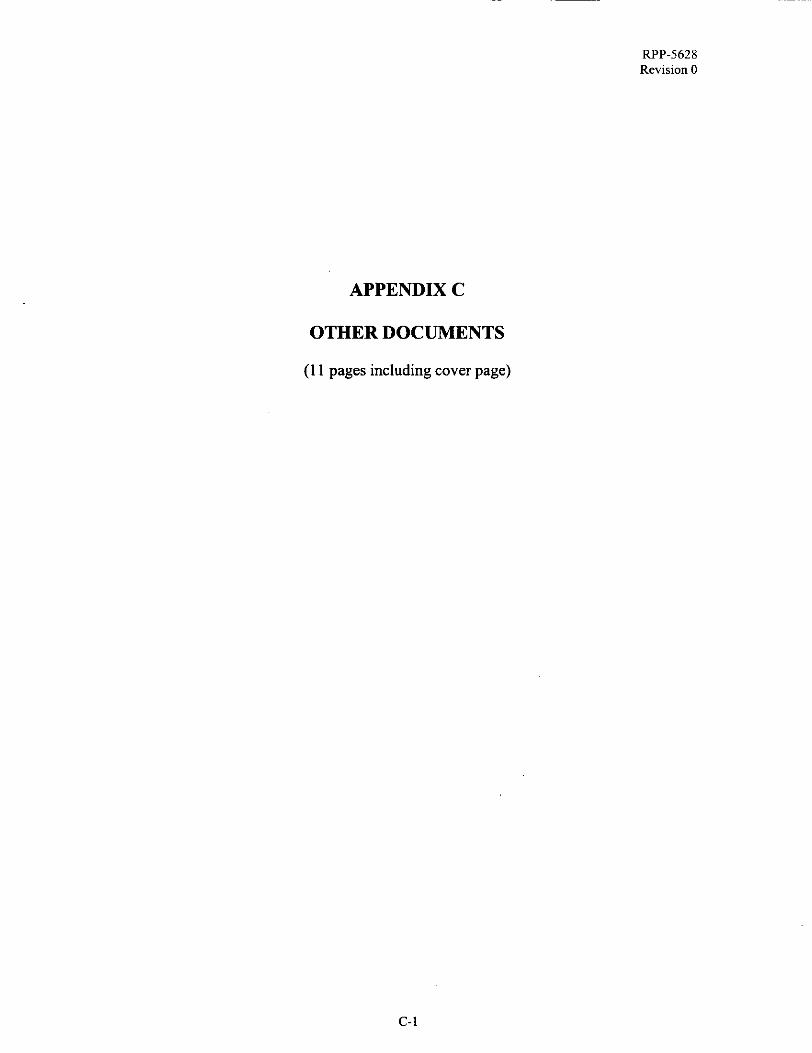
UNCTIONAI, TESTDIGPER DWG. H-2-690138 GENERALNOTE #8. TESTS 7 & 8. WESE TESTS ARE FOR UNIT #2.
qOTIFY HENRY SHUMAJCE 376-3404 AND ERIC WALDO 373-9207 FOR THEIR SPECIAL INSTRUCTIONS AND INPUT IN THE FOLLOWING TEST. THE DRlLL STRING WILL BE SUPPLIED BY CUSTOMER
?On: TESTING TO BE PERFORMED M T H 100 PSIG SUPPLY PRESSURE.
WNCTTONAL TESTS:
7. VERIFY THAT THE DISTANCE BETWEEN THE CLOSED JAWS IS LESS THAN 2 W . c---
:raft Signature 2, h h y ~ r n( I / , +,
2C Signature Date 8-3/-<9
Date f%-,?/-,7y / " '
8. VERIFY BY USING A STOPWATCH AND RECORDING THE TIME PASSED FOR THE CLOSMG OF THE JAWS ON THE F O O T C L W . JAW CLOSURE RATE NOT TO EXCEED ONE FOOT PER SECOND.
CLOSURE RATE IS a / SECOND@) FOR 3 %' '' INCHES. - /
Xaft Signature /-UA, Date 8-3/-79 2C Signature Date 3-31-99
/ '
PAGE~V OF QC IWECTION RE608D WORK ORDER 2H9903622lF
C-8

FUNCTIONAL TESTING PER DWG. H-2-690138 GENERAL NOTE #8. TESTS 1 t h 3. THESE TESTS ARE FOR UNIT #3.
NOTIFY HENRY SHUMAKE 376-3404 AND ERIC WALDO 373-9207 FOR THEIR SPECIAL INSTRUCTIONS AND INPUT IN THE FOLLOWING TEST. THE DRILL STRING WILL BE SUPPLIED BY CUSTOMER “GO GAGE” IS LOCATED IN THE MACHINE SHOP TOOL CRIB.
NOTE: FOR THE PURPOSE OF THIS DOCUMENT, SLIPPAGE IS DEFINED AS THE MOVEMENT OF THE DRILL STRING RELATIVE TO THE FOOTCLAMP JAWS >0.25 INCH.
TESTING TO BE PERFORMED WITH I00 PSIG SUPPLY PRESSURE.
FUNCTIONAL TESTS:
1. VERIFY THAT SUPPORT OF AMINTMUM VERTICAL LOAD OF 1000 POUNDS FORCE
SLIPPAGE. APPLIED TO 2 !4”, NON-FLUTED DRILL STRWG HELD BY FOOTCLAMF’ WITHOUT
Ad/ Date k-?/-pT //-.- Craft Signature
QC Signature Date P-~/-J-T / I /
2. VERIFY THAT FOOTCLAMP DOES NOT OPEN UPON LOSS OF SUPPLY AIR. AIR IS TO BE REMOVED FOR THIS TEST.
/-
Craft Signature I ) . f&4 .?) A/. Date$--3/-7/
QC Signature Date 6’3/-F’r
3. VERIFY THAT THE 01.895 x 12” “GO GAGE” PASSES THROUGH THE NON-FLUTED DRILL STRING PRIOR TO AND WHILE BEING CLAMPED M THE FOOTCLAMP.
Craft Signature ,-A A’,,- Date g - 3 1 - 9 QC Signature 69 Date Y>/<f
I ,, I -
PAGES, OF QC IN$PECTION RECOHO WORK ORDER 2H9903622m
c-9

@@$J,
., .:. .. 200
V
i
V
f.
V
&
FUNCTIONAL TESTINGPERDWG. H-2-690138 GENERAL NOTE #8. TESTS 4 t h 6. THESE TESTS ARE FOR UNIT #3.
NOTIFY EiENRY SHUMAKE 316-3404 AND ERIC WALDO 313-9201 FOR THEIR SPECIAL INSTRUCTIONS AND INPUT IN THE FOLLOWING TEST. THE DRILL STRING WILL BE SUPPLIED BY CUSTOMER.
NOTE: FOR THE PURPOSE OF THIS DOCUMENT SLIPPAGE IS DEFINED AS THE MOVEMENT OF THE DRILL STHNG RELATIVE TO THE FOOTCLAMP JAWS >0.25 INCH.
TESTING TO BE PERFORMED WlTH IO0 PSIG SUPPLYPRESSURE.
FUNCTIONAL TESTS:
4. VERIFY THAT SUPPORT OF A MINIMUM VERTICAL LOAD OF 1000 POUNDS FORCE APPLIED TO 2 %”, FLUTED DRILL STRWG HELD BY FOOTCLAMP WITHOUT SLIPPAGE.
Craft Signature /* n.\.,/ -4 / L- Date g-3/-,99 QC Signature Date r-T/-.C/
I-
\/ ‘
5. VERIFY THAT FOOTCLAMP DOES NOT OPEN UPON LOSS OF SUPPLY AIR. AIR IS TO BE REMOVED FOR THIS TEST.
&L./ Date G - c ) / - .A/ ,,/ I
2 Craft Signature
QC Signature Date S - T / - f f
6. VERIFY THAT THE 01.895 x 12” “GO GAGE” PASSES THROUGH THE FLUTED DRILL STRING PRIOR TO AND WHILE BEING CLAMPED IN THE FOOTCLAMP. I
Craft Signature 1 b L / , c/ /(/A Date k-s’/-%9
QC Signature OYH Date F*3/0[,f
(2-10

RI’P-5628 Re\,ision 0
3JNCTIONAL TESTINGPERDWG. H-2-690138 GENERALNOTE #8. TESTS 7 & 8. rHESE TESTS ARE FOR UNIT #3.
YOTIFY HENRY SHUMAm 3763404 AND E N C WALDO 373-9207 FOR THEIR SPECIAL INSTRUCTIONS AND INPUT IN THE FOLLOWING TEST. THE DRILL STRING WILL BE SUPPLIED BY CUSTOMER
g0m: TESTING TO BE PERFORMED w7TH 100 PSIG SUPPLY PRESSURE.
TNCTIONAL TESTS:
7. VERIFY THAT THE DISTANCE BETWEEN THE CLOSED JAWS IS LESS THAN 2 %”
lA-4 , “ Date ,C?--f/ r - Sp :raft Signature q /” I
?C Signature Date 9 ‘ 3 ~ -95
8. VERIFY BY USING A STOPWATCH AND RECORDING THE TIME PASSED FOR THE CLOSING OF THE JAWS ON THE FOOTCLAMP. JAW CLOSURE RATE NOT TO EXCEED ONE FOOT PER SECOND.
CLOSURE RATE IS /- SECOND@) FOR 3 %’ INCHES. I /
. c-
A4 Date k--?’/-F9 , :raft Signature
2C Signature Date 8-3/-99 /
WORK ORDER 2H9903622m PAGE,$/ OF
c-11

DISTRIBUTION SHEET
To Distribution
From Page 1 of 1 Equipment Engineering
I Formal Design Review- Foot Clamp Modification Project Ti tWork Order
EDTNo. 628086
Date 01/20/00
Name Attach'' EDTlECN Text With All Text Only Appendix Attach. Onlv Only
MSlN
IM. L. McElrov
T. R. Farris
C. D. Jackson
G. P. Janicek
I 57-07 I X I
S7-12 X
s7-34 X
S7-12 X
I T. C. Oten
H. F. Shumake
J. S. Scholfield
I R1-56 X
57-12 X
57-12 X
Central Files
DPC
DOE Readins ROOQ
B1-07 X
H6-08 X
H2-53 X
t PNNL Tech Librarv I P8-55 I x I I
A-6000-135 (1OB7)