Embed Size (px)
Citation preview

G E N E R A L @ E L E C T R I c

C O N T E N T S
TEXT
INTRODUCTION . . . . . . . . . . . . . . . . . . . . . . . . . . . . . . . . . . . . . . . . . . 1
SURGICAL TECHNIQUE . . . . . . . . . . . . . . . . . . . . . . . . . . . . . . . . . . . 3 Abdominal Implant . . . . . . . . . . . . . . . . . . . . . . . . . . . . . . . . . . . 3 Axillary Implant . . . . . . . . . . . . . . . . . . . . . . . . . . . . . . . . . . . . . 9
EXTERNAL RATE CONTROL . . . . . . . . . . . . . . . . . . . . . . . . . . . . . . . . 11
HANDLING AND STERILIZING INSTRUCTIONS . . . . . . . . . . . . . . . 13
CHECKING OPERATION AND HOW TO ORDER . . . . . . . . . . . . . . 13
FIGURES
1 . Abdominal Wall Implant . . . . . . . . . . . . . . . . . . . . . . . . . . . . . . 4
2 . General Electric Implantable Pacemaker . . . . . , . . . . . . . . . . . . 6 3 . Heart Attachment . . . . . . . . . . . . . . . . . . . . . . . . . . . . . . . . . . . . 8
4 -Axillary Implantation Technique . . . . . . . . . . . . . . . . . . . . . . . . 10
5 . External Rate Control . . . . . . . . . . . . . . . . . . . . . . . . . . . . . . . . . 12
The General Electric Pacemaker was developed in conjunction with Adrian Kantrowitz. M . D., Maimonides Hospital of Brooklyn. Brooklyn. New York .
i

INTRODUCTION
The General Electric Cardiac Pacemaker is a miniature implantable energy pulse generator for the correction of heart block or Stokes- Adams seizures. The miniature transistorized implantable pacemaker powered by long life mercury batteries was developed by the Elec- tronics Laboratory of the General Electric Company in conjunction with Dr. Adrian Kantrowitz of the Maimonides Hospital, Brooklyn, New York.
The rate of the pacemaker i s about 70 pulses per minute. This has been found adequate in the majority of cases where average physical activity i s maintained. For greater activity or periods of stress, an external control may be applied to temporarily raise the rate to any desired level between 75 and 120 pulses per minute. Removal of the external control automatically returns the pacemaker to its original rate. For special circumstances, the pacemaker may be built with higher or lower rates. It may be kept indefinitely at a higher rate with the external control but the minimum rate cannot be lowered. Battery life is not diminished in the implantable pacemaker by con- tinued use of the external control.
The research leading to the development of the pacemaker estab- lished that the heart i s an energy-sensing organ requiring five micro- joules of energy for stimulation. This threshold energy must be de- livered with a minimum of approximately two volts but is also depend- ent on sufficient energy produced by voltage and current flow for a certain pulse length. The minimum required threshold of five micro- joules i s observed to increase to approximately 15 micro-joule threshold over a long period of time after implanting.
To achieve reliable heart stimulation, it i s desirable to approxi- mately double the voltage and energy required by the heart. The pulse height i s established, therefore, at about 3.7 volts. The pulse energy decreases with pulse rate when the external control i s used, so the energy chosen is 35 micro-joules a t 120 pulses per minute. This results in a pulse energy input of 65 micro-joules at the base rate of 70 pulses per minute, or approximately four times the required energy.
This energy i s supplied b y five mercury batteries. The batteries are chosen for the high standards of reliability established by the manu- facturer and are carefully handled prior to assembly; therefore, failure due to premature battery rundown should be rare.
1

All other components in the pacemaker are also of high established reliability. Each part is chosen because of its ability to meet very rigid Government reliability standards. Each part i s then carefully tested above, below, and at body temperature. The components are then arranged in matched sets to assure that all active elements meet rigid specifications. The pacemaker is then assembled, the desired frequency is obtained by changing circuit time constants, and the output i s measured. Four separate tests are conducted on the assem- bled pacemaker during the soldering, encapsulating, sealing in silicone rubber, and packaging for shipment.
Physically, the pacemaker is a silicone rubber encased device weighing approximately five ounces. It is 2.5 inches long, 2.25 inches wide, and 1.0 inches thick. Two lead wires, each 21.9 inches long, made of No. 316 stainless steel sutures are sealed into the unit for attachment to the heart. The lead cable 0.015 inch in diameter i s made of 49 individual wires in 7 bundles. Each wire is less than two-thousandths of an inch in diameter. The lead wires are insulated by two layers of silicone rubber to provide electrical isolation and a Dacron web i s placed between the two layers which adds to the tensile strength of the lead. Two centimeters of these leads are left uninsulated to act as electrodes. Surgical needles are connected to the ends of the leads to facilitate attachment to the heart.
2

THE GENERAL ELECTRIC IMPLANTABLE CARDIAC PACEMAKER SURGICAL TECHNIQUE OF PACEMAKER IMPLANTATION
JOE D. MORRIS, M.D. Section of Thoracic Surgery
university of Michigan Medical Center
The technique of installing the General Electric implantable pacemaker is not difficult and many variations will undoubtedly be employed. In experience gained at the University of Michigan Medical Center and St. Joseph Mercy Hospital in Ann Arbor the following methods have proved to be most reliable.
An interim technique for pacing the heart must be employed during the period of operation prior to the time the implantable pacemaker electrodes have been secured in the myocardium. This is most con- veniently accomplished using an endocardial electrode of bi-polar design. The catheter electrode i s introduced by way of the left basilic vein and its tip positioned in the right ventricular outflow tract. The heart is then paced by electrical pulse delivered through the endo- cardial electrode by means of any standard external pacemaker de- vice. i f the endocardial electrode remains in position longer than twenty-four hours the chance of perforation of the right ventricle by the tip of the electrode is increased. For this reason the implantation of the permanent pacemaker is carried out promptly after positioning the endocardial catheter electrode.
Interim pacing by way of skin electrodes while effective introduces interference due to contraction of chest wall musculature.
The pacemaker i s implanted under general intratracheal anesthesia providing for pulmonary ventilation throughout the operation.
Two methods of implantation have been employed successfully. The abdominal wall implantation (Figure 1) of the electronic package which has been the most widely employed technique and the left axillary implantation technique (Figure 4) which has been reserved for special circumstances which will be dealt with later.
ABDOMINAL IMPLANTATION TECHNIQUE The patient is placed in a dorsal recumbent position (supine), with the left arm abducted on an arm board. The entire left chest, left axilla and abdomen are prepared and draped. The pocket to accom- modate the pacemaker unit is first developed in the left upper quad- rant. A three inch transverse incision is made over the left rectus
3
ABDOMINAL WALL IMPLANT - FIGURE 1
4

muscle at the level of the umbilicus or slightly higher. The incision is de- veloped to the level of the rectus fascia and this surface cleared for an area slightly larger than the face of the pacemaker. This should allow for approximation of the wound edges over the pacemaker without tension. The resulting bulge i s well tolerated and the waist- line rides above the prominence.
A left submammary incision is made and the pleural space entered through the fifth intercostal space. An extracostal tunnel i s developed from the lateral end of the submammary incision extending down over the costal margin to communicate with the lateral aspect of the pocket in the left upper quadrant. A short incision in the anterior rectus fascia i s necessary to complete this tunnel communication. This more lateral course of the tunnel provides greater protection of the leads as they are subject to less deformity and flexion during bending of the torso. The pacemaker unit is then placed in the abdominal pocket. The needles swedged on the electrode leads are sheathed in their protective tubing prior to pulling the leads through the tunnel. The leads are most easily drawn through the tunnel by looping a piece of umbilical tape around the leads distal to the proximal heavy insulation. Care should be exercised not to pull the tape so tight that the lead becomes kinked. The polyethylene tubes sheathing the electrode needles are not removed until just before implanting the electrode in the myocardium. Care i s taken to avoid grasping the leads in the jaws of a hemostat. Under no circumstances should the bare electrodes be grasped by an instrument. Pulling the leads through the tunnel by grasping the needles may result in detachment of the needles at the swedge.
Exposure of the Heart Exposure of the pericardium is accomplished by a rib spreader which opens the fifth interspace for approximately four inches, care is taken to avoid catching the leads between the rib and the retractor. The pericardium is opened vertically along its anterior lateral aspect well anterior to the phrenic nerve. The avascular portion of the left ven- tricle i s selected for electrode implantation.
Method of Implantat ion The leads are led from the extracostal tunnel through the fifth inter- costal space at the anterior axillary line, The thirteen-inch length of heavy insulation provides adequate protection to the leads as they enter the thorax between the fifth and sixth ribs (Figure 2). A gentle curve i s fashioned to bring the leads to the midline of the mediastinum whence they are lead cephalad to the base of the heart and brought
5

GENERAL ELECTRIC IMPLANTABLE PACEMAKER - FIGURE 2
6

down to the surface of the left ventricle. This route is important as it minimizes the flexion to which leads are subjected to by myocardial contractions. Care should be taken to avoid sharp bending of the leads at the taper where the heavy tubing insulation gives way to progres- sively thinner insulation. One of the individual electrodes is then led into the avascular portion of the left ventricle at the base of the heart directed toward the apex (Figure 3). The tip of the curved needle should exit from the myocardium approximately fifteen millimeters from its point of introduction. Care is taken to avoid entering the ventricular cavity with this suture pass.
After the needle i s withdrawn from the myocardium the bare electrode i s grasped with the fingers and the electrode drawn along the needle path in the myocardium until the insulated portion of this single elec- trode enters and exits from the myocardium along the needle path. Pulling the electrode into position by means of a needle holder ap- plied to the needle may result in separation of the needle from the electrode at the swedge. The needle is then reintroduced into the myocardium close to the point of exit of the electrode and passed in a reverse direction toward the base of the heart making a parallel path with the initial suture pass. The bare electrode i s withdrawn from the heart until a small metal flange comes into view.
A 3-0 Dacron ligature i s then used to ligate the bare electrode to the insulated proximal electrode placing the knot below the level of the metal flange. The needle i s then cut off the electrode distal to the metal flange. The same procedure i s followed implanting the second electrode parallel to the first so that the distance between the bare electrodes i s one centimeter. The second electrode should be placed so that the last suture pass i s adjacent to the last suture pass of the previous electrode positioning providing for a zone of myocardium free of injury between the bare electrodes (Fig. 3).
If the heart is being paced by an endocardial electrode this pace- maker should be turned off as the second electrode is implanted in the myocardium. If the myocardial implantation i s too close to the apex of the ventricle stimulation of the phrenic nerve may result. The thoracotomy wound is closed in the usual manner employing thora- cotomy tube drainage for as long as may be required. Prior to clos- ing the incision in the left upper quadrant the thin silicone-impregnated dacron flaps on either side of the pacemaker unit are sutured with four nonabsorbable sutures to the rectus fascia to prevent migration or rotation of the unit during the healing stage.
7 *See diagram and footnote, p. 8.

HEART ATTACHMENT - FIGURE 3 ++Approximately 1.5 cm. of the distal end of the insulated lead is permanently positioned in the myocardium. Failure to observe this detail may result in early lead breakage at this point.
8

AXILLARY IMPLANTATION ALTERNATE TECHNIQUE, FIGURE 4
Younger patients with greater activity potential prefer the left axillary implantation site for the pacemaker package as this location interferes less with body motion and bending. Wearing apparel i s more com- fortable than with the abdominal implantation which requires men to wear loose clothing and suspenders. Belts may be uncomfortable for some patients with abdominally placed pacemaker. In obese pa- tients there may be an increased tendency for the pacemaker to mi- grate in the abdominal implantation site or rise on edge and turn over, stressing the leads or even pulling them out of the myocardium. This has happened in spite of suturing the suture pad adequately to the rectus fascia. The above circumstances have led to the use of the axillary implantation site with encouraging results.
In the axillary implantation the operation is carried out with the pa- tient in the same position, supine, with the left arm abducted. The anterior chest and left axilla are prepared and draped. A submam- mary incision, five to six inches in length, is developed over the fourth or fifth intercostal space and the pleura entered through the most appropriate space as determined by the surgeon. The pocket to ac- commodate the pacemaker package is developed extracostally by undermining the lateral aspect of the wound along the axis of the intercostal incision. Care i s taken to maintain absolute hemostasis during the development of this pocket otherwise hematoma formation will be impressive in the loose areolar tissue of the axilla.
The pocket i s developed as far posteriorly a s the midaxillary line. The pacemaker package is then placed in the axillary pocket and the leads which are of shorter dimension (fifteen inches) on axillary models are led through the intercostal space to the midline of the anterior mediastinum. The leads are then swept cephalad and curved to the left being brought down in a gentle arc to the base of the left ventricle where implantation is carried out in the usual manner. Use of the standard abdominal implantation model for axillary implanta- tion requires the placement of an extra loop in the region of the anterior mediastinum to take up the extra slack in lead length.
Lead Handling Care should be taken to avoid making any sharp turns or acute angles in manipulating the pacemaker leads. An ample length of lead ma- terial is provided with the unit to allow sufficient slack between the point of electrode implantation and the site of the pacemaker package.
9

AXILLARY IMPLANT - FIGURE 4
10

EXTERNAL RATE CONTROL
The General Electric External Rate Control (Figure 5) is used for in- creasing the basic rate of an implanted General Electric cardiac pace- maker to any rate to approximately 120 pulses per minute. The Ex- ternal Rate Control consists of an induction coil and the electronic control. The induction coil i s plugged into the control and placed with GE monogram away from patient's skin directly above the im- planted pacemaker. The electronic control can be placed in the pa- tient's shirt pocket, other pocket, held to the body with a loose fitting strap or otherwise placed in a convenient location. The External Rate Control i s energized by switching the slide switch to "ON." The rate i s adjusted by rotating the knurled round knob. The rate will increase from the basic rate at "A" position on the con- trol knob to a maximum rate of "G" position, near 120 pulses per minute. Return to the basic pacemaker rate results from removing the coil from near the implanted pacemaker. The electronic control should be switched to "OFF" position when not in use to save bat- tery energy. The advantage of the External Rate Control unit is its ability to elevate the heart rate to meet increased physiological demands of the patient. Such demands are usually temporary and intermittent. An increase in pulse rate to approximately 80 to 85 per minute may be of con- siderable benefit to some patients in the early postoperative phase, particularly those patients who may manifest slight hypotension in this phase of their recovery. Similarly the Rate Control i s of value in subsequent illnesses or operations. Younger patients or those with more activity potential because of an otherwise healthy state may welcome the External Rate Control as a means of increasing their level of activity a t will. The Rate Control unit may serve as a means of checking the threshold of myocardial response. As the rate i s in- creased the energy pulse is decreased. Failure of the heart rate to increase above 90 per minute may indicate a minimal reserve above threshold for pacing, thereby warning of eventual pacing difficulty.
Required care of the External Rate Control is minimal. With normal handling, it i s rugged and highly reliable. The case i s not waterproof. Battery life depends on initial charge of the battery and how many hours a day it is in use. When the External Rate Control appears to operate poorly, first re- place the battery with a new one. If the difficulty persists, return it to Pacemaker, General Electric Company, X-Ray Department, 4855 West Electric Avenue, Milwaukee, Wisconsin 53201.
11

GENERAL ELECTRIC EXTERNAL RATE CONTROL - FIGURE 5
12

GENERAL INSTRUCTIONS Handling The pacemaker is a reliable, rugged device, but certain precautions should be taken in its use. Normal transportation handling will not damage the pacemaker elec- tronic package. Care should be exercised to insure that the elec- trodes and lead wires do not become kinked, abraded or nicked. Out of the package, the pacemaker should not be dropped. In the event that it i s dropped from a height greater than six inches, the unit should not be implanted. Care should be taken to avoid contaminating the silicone rubber cov- ering. Silicone rubber has a static attraction and affinity for surface contaminants such as fingerprints, dust, lint, talc, starch and many other materials which can evoke foreign body reactions. Handling with lint-free sterile surgical gloves is recommended. Should the pacemaker become contaminated, it should be thoroughly washed and rinsed in distilled water.
Do not autoclave e pacemaker. Any cold or ethylene oxide method of steriliz t'o may be used in which the pacemaker i s not heated above 15" .*The pacemaker should be very carefully washed after
not be left in sterilizing solutions for periods in excess of 24 hours. Checking Operation To check operation of the pacemaker, either in or out of a patient, place a small radio, like a pocket transistor radio, on top of the pace- maker, tune between stations and turn to full volume. Hold the pace- maker leads shorted together. The pacemaker pulse will be heard as a small click at a rate below 60 pulses per minute. To simulate im- planted conditions, connect a 300 ohm, 5% tolerance resistor and a 20 microfarad, 10% tolerance capacitor in series with the electrodes. This will approximately produce the implanted pulse rate. H o w to Order The General Electric cardiac pacemaker and external rate control is sold directly to hospitals and members of the medical profession. Vital Evaluation Information is requested to be returned to the General Electric Company. For convenience forms are furnished with each unit shipped. Orders may be placed directly with Pacemaker, General Electric Co., X-Ray Dept., 4855 W. Electric Ave., Milwaukee, Wisconsin 53201 - Telephone number: (414) - 383-3211 - or by contacting a General Electric Company, X-Ray Dept. Medical Sales Office.
Sterilizing /.?!P/f
sterilizatio d , ventilated and then rinsed in sterile water. It should
13

P A C E M A K E R H E L I C A B L E E L E C T R O D E S
i N T E R l M CHANGES in procedure for Implanting H E L I C A B L E Electrodes
of the G-E Pacemaker

HELICABLE ELECTRODES
INTERIM CHANGES in Procedure f o r Implanting HELICABLE Electrodes of the G-E Pacemaker
1. REMOVE - The tubular Plug on the connector of the Pulse Gen- e r a t o r should be removed before sterilization. used to re tard the discharge of the Pulse Generator during s torage and shipment and pr ior to implanting.
This Plug is
2 . STERILIZING - The electrodes may be s ter i l ized by autoclaving. DO NOT AUTOCLAVE THE PULSE GENERATOR. F o r s t e r i l - ization of the Pulse Generator see "Cardiac Pacemaker" booklet, page 13.
3 . CONNECTOR - The integral connector allows the electrodes to be s ter i l ized and implanted before attaching to the Pulse Generator . The electrodes a r e designed to be drawn connector end f i r s t through. any tunnel preparat ions during implanting. twists and kinks. The protective cover on the connector should be removed just p r ior to engagement with the Pulse Generator .
This will tend to avoid
4. HEART ATTACHMENT - Two suture p a s s e s a r e made for each electrode (See Revised Figure 3 on back cover of this Interim Changes). end is to be drawnin to the myocardium to the place where it abrupt- ly increases in cross-sect ion. neares t the suture needle, there is a cone on the electrode which should protrude from the myocardium 4 o r 5 mm. pass (this t ime bare electrode) is drawn, this cone will provide a st rain-rel ief pad for the exposed loop of electrode.
On the f i r s t pass the insulation on the h e a r t attachment
At the forward end of the insulation,
After the second
5. FERRULES - One pure s i lver fe r ru le is required for each e lec- trode. It i s to be placed and attached p r i o r to cutting off the needle. Be s u r e to c r i m p the fe r ru le snugly, using the tool furnished from General Electr ic . Each electrode contains 49 smal l tempered s t rands laid together, which, when severed, will f la re , o r unravel. The snugly cr imped fe r ru le prevents this condition when cutting off the needle.

6. ATTACHMENT OF PULSE GENERATOR - Remove protective cover f rom electrode connector by rolling it off like a rubber glove. double sea l is provided. The pins and sockets a r e aligned by means of a key. The meta l s leeve of the Pulse Generator f i t r over the meta l s leeve of the electrode connector. The inner ailicon tubing of the electrode fits over the metal s leeve of the P u l r e Generator and will butt against the shor t length protruding from the Pulse Generator . The outer length of tubing on the electrode will fit over the shor t length protruding from the Pulse Generator and will butt against the Pulse Generator case. G r a s p the electrode and the Pulse Generator f i rmly and, if aligned, they should engage with effort. Pinching the tubing around the connector as you apply, engaging p r e s s u r e will assist in bringing them into place.
A
7. MODE CONTROL - The Mode Control is a pencil shaped mag- netic device furnished with the Dual Mode pacemaker (not applicable to the "Single Basic Rate" pacemaker) . It has the words NORMAL (black) and ACTIVE ( red) engraved along the side, the le t te r "A" engraved on one end, and the G - E monogram engraved on the other end.
The Mode Control is used to change the ra te of the Dual Mode pacemaker f rom NORMAL (approx. 70 pulses p e r minute) to ACTIVE (approx. 85 pulses p e r minute) o r vice versa . It functions best when held within 4 cent imeters of the side of the P u l s e Gen- e r a t o r opposite the suture pad, and a t a level with and para l le l to the edge to which the leads attach. Normally the pacemaker will remain a t the rate s e t until changed.
Abdominal Implant: - Orient the Mode Control by holding it such that the selected word NORMAL o r ACTIVE can be read by the patient (upside down to the attending person) . Move it toward the implant site. When within the 4 cent imeter range the FWse Generator should be a t the selected ra te . Retract i t in the s a m e manner .
Axillary Implant: - Orient the Mode Control by holding it with the end bearing the G-E monogram pointed toward the pat ient ' s head for NORMAL rate o r the end bearing the le t te r "A" pointed toward the pat ient ' s head for ACTIVE rate . Move and r e t r a c t it as descr ibed above.
After implant you will want to check to make s u r e that the Mode Control functions properly.
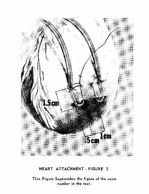
HEART ATTACHMENT - FIGURE 3
This Figure Supercedes the figure of the same number in the text.