Embed Size (px)
Citation preview
GUIDE FOR DEVELOPINGRCC SPECIFICATIONSAND COMMENTARY
Roller-Compacted Concretefor Embankment Armoringand Spillway Projects
Prepared by Gannett Fleming, Inc.
P O R T L A N D C E M E N T A S S O C I A T I O N
Roller-Compacted Concrete forEmbankment Armoring and Spillway Projects
GUIDEFOR DEVELOPING RCC
SPECIFICATIONS
P O R T L A N D C E M E N T A S S O C I A T I O N

Published by:Portland Cement Association5420 Old Orchard Road,Skokie, Illinois 60077-1083USAPhone: 847.966.6200Fax: 847.966.9781Internet: www.portcement.org
Print history:First edition 2000
© 2000 Portland Cement AssociationAll rights reserved. No part of this publication may bereproduced, stored in a retrieval system, or transmittedin any form or by any means, electronic, mechanical,photocopying, recording, or otherwise, without the priorpermission of the copyright owner.
Printed in United States of America
This publication is intended SOLELY for use by PROFESSIONALPERSONNEL who are competent to evaluate the significance andlimitations of the information provided herein, and who will accepttotal responsibility for the application of this information. The PortlandCement Association DISCLAIMS any and all RESPONSIBILITY andLIABILITY for the accuracy of and the application of the informationcontained in this publication to the full extent permitted by the law.
Acknowledgements
This Guide for Developing RCC Specifications was prepared for the Portland Cement
Association under the supervision of Mr. Randall P. Bass and Mr. Wayne Adaska. The primary
authors of the Guide were Rodney E. Holderbaum and Paul G. Schweiger of Gannett Fleming
Inc., with technical input from Ernest K. Schrader. The primary authors of the Commentary were
Rodney E. Holderbaum, Paul G. Schweiger, and Randall P. Bass. Technical review and editing
were provided by:
William B. Bingham, Gannett Fleming Inc., Technical ReviewDonald P. Roarabaugh, Gannett Fleming Inc., Technical Review and EditingStephen Tatro, Corps of Engineers, Technical Review - MaterialsJeffrey Allen, ASI-RCC Inc., Technical Review - Construction Issues
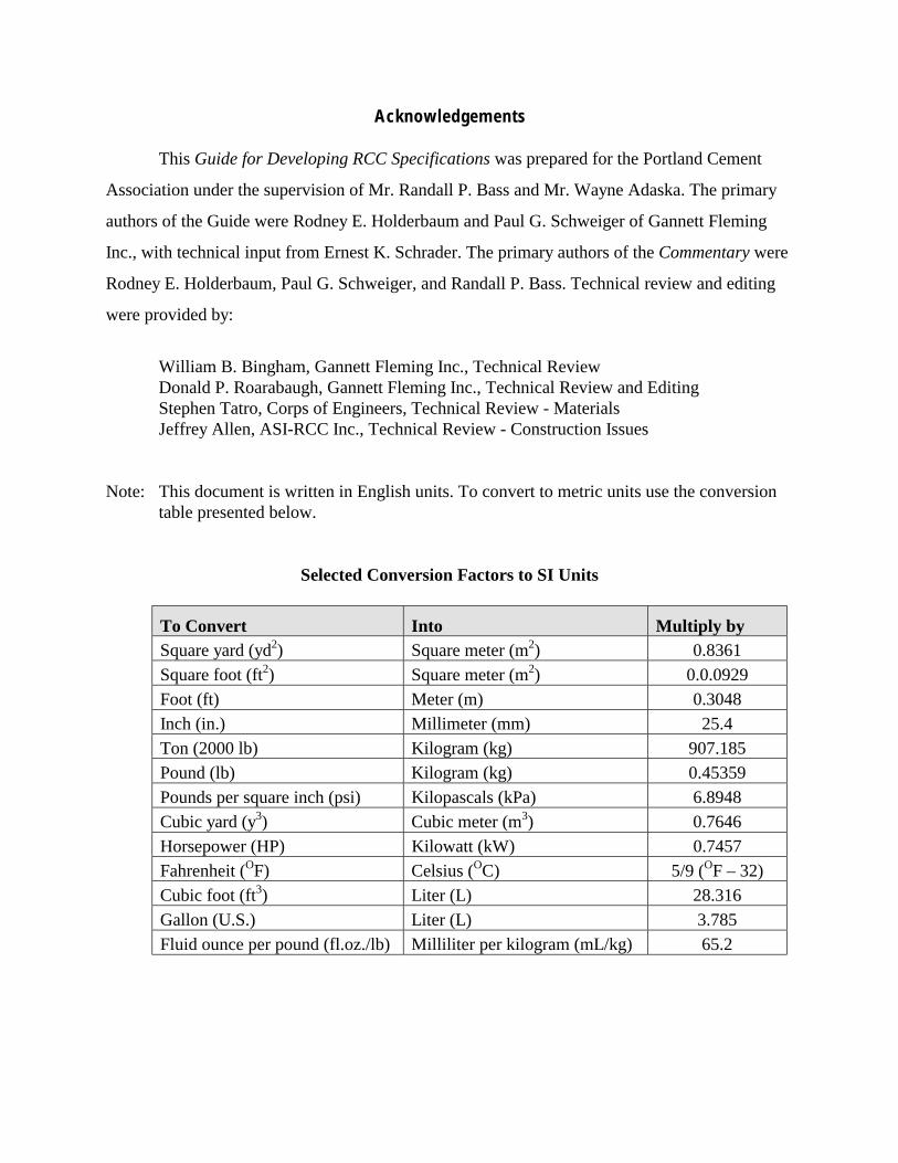
Note: This document is written in English units. To convert to metric units use the conversiontable presented below.
Selected Conversion Factors to SI Units
To Convert Into Multiply bySquare yard (yd2) Square meter (m2) 0.8361Square foot (ft2) Square meter (m2) 0.0.0929Foot (ft) Meter (m) 0.3048Inch (in.) Millimeter (mm) 25.4Ton (2000 lb) Kilogram (kg) 907.185Pound (lb) Kilogram (kg) 0.45359Pounds per square inch (psi) Kilopascals (kPa) 6.8948Cubic yard (y3) Cubic meter (m3) 0.7646Horsepower (HP) Kilowatt (kW) 0.7457Fahrenheit (OF) Celsius (OC) 5/9 (OF – 32)Cubic foot (ft3) Liter (L) 28.316Gallon (U.S.) Liter (L) 3.785Fluid ounce per pound (fl.oz./lb) Milliliter per kilogram (mL/kg) 65.2
i
Roller-Compacted Concrete forEmbankment Armoring and Spillway Projects
Guide for Developing RCC Specifications
Table of ContentsPAGE
INSTRUCTIONS FOR USE OF GUIDE SPECIFICATIONS.....................................................vii
PART 1 GENERAL .................................................................................................................... 1
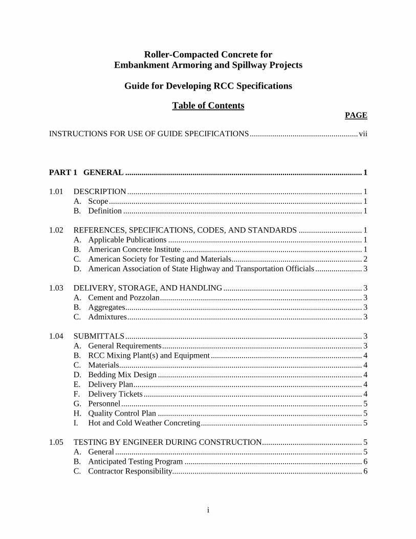
1.01 DESCRIPTION................................................................................................................... 1A. Scope............................................................................................................................ 1B. Definition ..................................................................................................................... 1
1.02 REFERENCES, SPECIFICATIONS, CODES, AND STANDARDS ............................... 1A. Applicable Publications ............................................................................................... 1B. American Concrete Institute ........................................................................................ 1C. American Society for Testing and Materials................................................................ 2D. American Association of State Highway and Transportation Officials ....................... 3
1.03 DELIVERY, STORAGE, AND HANDLING .................................................................... 3A. Cement and Pozzolan................................................................................................... 3B. Aggregates.................................................................................................................... 3C. Admixtures................................................................................................................... 3
1.04 SUBMITTALS.................................................................................................................... 3A. General Requirements.................................................................................................. 3B. RCC Mixing Plant(s) and Equipment .......................................................................... 4C. Materials....................................................................................................................... 4D. Bedding Mix Design .................................................................................................... 4E. Delivery Plan................................................................................................................ 4F. Delivery Tickets ........................................................................................................... 4G. Personnel...................................................................................................................... 5H. Quality Control Plan .................................................................................................... 5I. Hot and Cold Weather Concreting............................................................................... 5
1.05 TESTING BY ENGINEER DURING CONSTRUCTION................................................. 5A. General ......................................................................................................................... 5B. Anticipated Testing Program ....................................................................................... 6C. Contractor Responsibility............................................................................................. 6
ii
Roller-Compacted Concrete forEmbankment Armoring and Spillway Projects
Guide for Developing RCC Specifications
Table of Contents
PART 2 PRODUCTS ................................................................................................................ 6
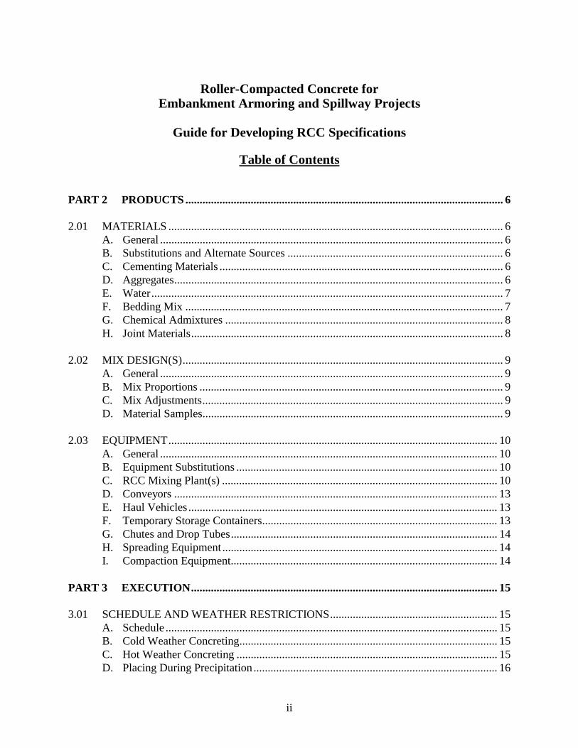
2.01 MATERIALS ...................................................................................................................... 6A. General ......................................................................................................................... 6B. Substitutions and Alternate Sources ............................................................................ 6C. Cementing Materials .................................................................................................... 6D. Aggregates.................................................................................................................... 6E. Water............................................................................................................................ 7F. Bedding Mix ................................................................................................................ 7G. Chemical Admixtures .................................................................................................. 8H. Joint Materials.............................................................................................................. 8
2.02 MIX DESIGN(S)................................................................................................................. 9A. General ......................................................................................................................... 9B. Mix Proportions ........................................................................................................... 9C. Mix Adjustments.......................................................................................................... 9D. Material Samples.......................................................................................................... 9
2.03 EQUIPMENT.................................................................................................................... 10A. General ....................................................................................................................... 10B. Equipment Substitutions ............................................................................................ 10C. RCC Mixing Plant(s) ................................................................................................. 10D. Conveyors .................................................................................................................. 13E. Haul Vehicles ............................................................................................................. 13F. Temporary Storage Containers................................................................................... 13G. Chutes and Drop Tubes.............................................................................................. 14H. Spreading Equipment ................................................................................................. 14I. Compaction Equipment.............................................................................................. 14
PART 3 EXECUTION............................................................................................................ 15
3.01 SCHEDULE AND WEATHER RESTRICTIONS........................................................... 15A. Schedule ..................................................................................................................... 15B. Cold Weather Concreting........................................................................................... 15C. Hot Weather Concreting ............................................................................................ 15D. Placing During Precipitation ...................................................................................... 16
iii
Roller-Compacted Concrete forEmbankment Armoring and Spillway Projects
Guide for Developing RCC Specifications
Table of Contents
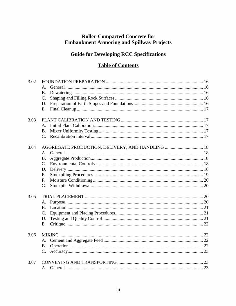
3.02 FOUNDATION PREPARATION .................................................................................... 16A. General ....................................................................................................................... 16B. Dewatering ................................................................................................................. 16C. Shaping and Filling Rock Surfaces ............................................................................ 16D. Preparation of Earth Slopes and Foundations ............................................................ 16E. Final Cleanup ............................................................................................................. 17
3.03 PLANT CALIBRATION AND TESTING ....................................................................... 17A. Initial Plant Calibration.............................................................................................. 17B. Mixer Uniformity Testing .......................................................................................... 17C. Recalibration Interval................................................................................................. 17
3.04 AGGREGATE PRODUCTION, DELIVERY, AND HANDLING ................................. 18A. General ....................................................................................................................... 18B. Aggregate Production................................................................................................. 18C. Environmental Controls ............................................................................................. 18D. Delivery...................................................................................................................... 18E. Stockpiling Procedures .............................................................................................. 19F. Moisture Conditioning ............................................................................................... 20G. Stockpile Withdrawal................................................................................................. 20
3.05 TRIAL PLACEMENT ...................................................................................................... 20A. Purpose....................................................................................................................... 20B. Location...................................................................................................................... 21C. Equipment and Placing Procedures............................................................................ 21D. Testing and Quality Control....................................................................................... 21E. Critique....................................................................................................................... 22
3.06 MIXING ............................................................................................................................ 22A. Cement and Aggregate Feed ...................................................................................... 22B. Operation.................................................................................................................... 22C. Accuracy..................................................................................................................... 23
3.07 CONVEYING AND TRANSPORTING .......................................................................... 23A. General ....................................................................................................................... 23
iv
Roller-Compacted Concrete forEmbankment Armoring and Spillway Projects
Guide for Developing RCC Specifications
Table of Contents
B. Temporary Storage Containers................................................................................... 23C. Conveyors and Haul Vehicles .................................................................................... 23
3.08 PLACING AND SPREADING......................................................................................... 24A. General ....................................................................................................................... 24B. Temperature Restrictions ........................................................................................... 24C. Layout of the Placement Area .................................................................................... 25D. Depositing .................................................................................................................. 25E. Lift Thickness............................................................................................................. 26F. Spreading ................................................................................................................... 26
3.09 COMPACTION ................................................................................................................ 27A. Determination of Optimum Compaction Density Value ........................................... 27B. Compaction ................................................................................................................ 27C. Acceptance ................................................................................................................. 27D. Additional Compaction .............................................................................................. 28E. Removal of Material .................................................................................................. 28F. Exposed Edge Compaction ........................................................................................ 28
3.10 LIFT AND CONTRACTION JOINTS ............................................................................. 28A. General ....................................................................................................................... 28B. Routine Lift Surface Treatment ................................................................................. 28C. Lift Surface Cold Joints ............................................................................................. 29D. Lift Edge Cold Joints ................................................................................................. 29E. Contraction Joints (Vertical Joints) ........................................................................... 29
3.11 REINFORCING STEEL AND ANCHOR BARS ............................................................ 30A. General ....................................................................................................................... 30B. Anchor Bars ............................................................................................................... 30C. Reinforcing Steel........................................................................................................ 30
3.12 CURING AND PROTECTION ........................................................................................ 30A. Cold Weather Protection............................................................................................ 30B. Moist Curing Requirements ....................................................................................... 30C. Use of Curing Compounds......................................................................................... 30
v
Roller-Compacted Concrete forEmbankment Armoring and Spillway Projects
Guide for Developing RCC Specifications
Table of Contents
3.13 FACING FINISH TREATMENT ..................................................................................... 31A. Forming...................................................................................................................... 31B. Unformed RCC .......................................................................................................... 31C. Formed RCC .............................................................................................................. 32D. RCC with Precast Panel Face..................................................................................... 33E. RCC with Conventional Concrete Face ..................................................................... 34F. RCC with Reinforced Concrete Face......................................................................... 36G. RCC Placed Concurrently with Fill Material............................................................. 37
3.14 INSTRUMENTATION..................................................................................................... 37A. General ....................................................................................................................... 37
3.15 STRUCTURAL TOLERANCES...................................................................................... 37A. General ....................................................................................................................... 37B. Specific Requirements ............................................................................................... 37
3.16 QUALITY CONTROL AND TESTING .......................................................................... 38A. General ....................................................................................................................... 38B. Aggregate Gradation .................................................................................................. 39C. Aggregate Moisture Determination............................................................................ 39D. Material Finer Than the No. 200 Sieve...................................................................... 39E. Aggregate Quantities.................................................................................................. 39F. Cement and Pozzolan Quantities ............................................................................... 40G. RCC Mixing Plant Control ........................................................................................ 40H. Scales for Weight Batching........................................................................................ 40I. Volumetric Feed Calibrations .................................................................................... 40J. Testing RCC Mixers .................................................................................................. 40K. Temperature ............................................................................................................... 41L. Moisture Content........................................................................................................ 41M. Mix Consistency (Vebe Time) ................................................................................... 41N. Cement and Pozzolan................................................................................................. 42O. RCC Specimens for Compression Tests .................................................................... 42P. Density ....................................................................................................................... 42Q. Compaction Equipment.............................................................................................. 43R. Dumping and Spreading............................................................................................. 43S. Preparation for Concrete Placement........................................................................... 44
vi
Roller-Compacted Concrete forEmbankment Armoring and Spillway Projects
Guide for Developing RCC Specifications
Table of Contents
T. Curing and Surface Protection ................................................................................... 44U. RCC Coring................................................................................................................ 45
PART 4 MEASUREMENT AND PAYMENT ..................................................................... 46
4.01 MEASUREMENT ............................................................................................................ 46A. General ....................................................................................................................... 46B. Pay Item Descriptions ................................................................................................ 46
4.02 PAYMENT........................................................................................................................ 46A. General ....................................................................................................................... 46B. Incidental Costs.......................................................................................................... 46
4.03 VARIATIONS IN QUANTITIES..................................................................................... 47
4.04 ITEM DESCRIPTIONS .................................................................................................... 47A. General ....................................................................................................................... 47B. Pay Item Descriptions (for unit price contracts) ........................................................ 48B. Roller-Compacted Concrete (for lump sum contracts) .............................................. 50
vii
Roller-Compacted Concrete forEmbankment Armoring and Spillway Projects
Guide for Developing RCC Specifications
Instructions for Use of This Guide Document
Information to assist the engineer with preparation of a specification for embankmentarmoring or spillway construction using roller-compacted concrete is provided in two differentformats within this document: (1) the Guide for Developing RCC Specifications, and (2) theCommentary. The Commentary is a companion document that provides additional guidance forspecifying equipment, materials, and construction procedures. The Guide for Developing RCCSpecifications was prepared using the CSI specification format.
The following paragraph titled “A. Schedule:” illustrates the use of the Guide Document.The items bracketed in bold type, (e.g. [6 days], [one 10-hour], [April 15]) are items orinformation that are project specific and need to be provided by the specification writer. Theitalicized paragraph following the specification is not part of the specification and is denoted as aseparate comment by the asterisks. This portion of the Guide Document is used to provideinformation to assist the specification writer with preparation of that particular specificationsection.
Example:
3.01 SCHEDULE AND WEATHER RESTRICTIONS
A. Schedule: It is the intent of this specification to construct the RCC in a continuousoperation to the extent practical. Weather permitting, schedule RCC placement [6 days]per week [one 10-hour] shift per day from the start of placement until completion. Beginplacement no later than [April 15] and complete by [June 15] of the [same year].
******************************************************************************
Insert placement time limits if required to limit peak temperatures and/or if the owner or localmunicipality has schedule or regulatory requirements that affect the contractor’s productionschedule.
Insert the appropriate dates paying attention to local climate conditions. For armoring andovertopping projects, temperature sensitivity is generally not a major concern. The RCCplacement window should be wide enough to afford the contractor flexibility.
******************************************************************************
1
Roller-Compacted Concrete forEmbankment Armoring and Spillway Projects
Guide for Developing RCC Specifications
PART 1 - GENERAL
1.01 DESCRIPTION
A. Scope: This section describes requirements for furnishing all plants, materials, andequipment, and performing all labor for the manufacturing, transporting, placing,compacting, testing, and curing of roller-compacted concrete (RCC).
B. Definition: Roller-compacted concrete is a combination of crushed rock and/or naturalsand, gravel, and/or soil having a controlled gradation to which cementing materials suchas cement or cement and pozzolan are added. The materials are blended with water to adamp consistency that can be hauled in vehicles or delivered with a conveyor, spread withearth-moving equipment in layers, and compacted with a vibratory roller.
1.02 REFERENCES, SPECIFICATIONS, CODES, AND STANDARDS
A. Applicable Publications:1. “Roller-Compacted Concrete,” Symposium Volume of the American Society of Civil
Engineers, May 1985.2. “Roller-Compacted Concrete II,” Symposium Volume of the American Society of
Civil Engineers, February 1988.3. “Roller-Compacted Concrete III,” Symposium Volume of the American Society of
Civil Engineers, February 1992.
B. American Concrete Institute:1. ACI 207.5, Roller-Compacted Mass Concrete2. ACI 211.1, Standard Practice for Selecting Proportions for Normal, Heavyweight,
and Mass Concrete3. ACI 214, Recommended Practice for Evaluation of Test Results of Concrete4. ACI 304, Guide for Measuring, Mixing, Transporting, and Placing Concrete5. ACI 305, Hot Weather Concreting6. ACI 306, Cold Weather Concreting7. ACI 308, Standard Practice for Curing Concrete8. ACI 309, Guide for Consolidation of Concrete9. ACI 318, Building Code Requirements for Structural Concrete
2
C. American Society for Testing and Materials:1. ASTM C 31, Practice for Making and Curing Concrete Test Specimens in the Field2. ASTM C 33, Specification for Concrete Aggregates3. ASTM C 39, Test Method for Compressive Strength of Cylindrical Concrete
Specimens4. ASTM C 40, Test Method for Organic Impurities in Fine Aggregates for Concrete5. ASTM C 42, Test Method for Obtaining and Testing Drilled Cores and Sawed
Beams of Concrete6. ASTM C 87, Test Method for Effect of Organic Impurities in Fine Aggregate on
Strength of Mortar7. ASTM C 94, Specification for Ready-Mixed Concrete8. ASTM C 127 Test Method for Specific Gravity Absorption of Coarse Aggregate9. ASTM C 128 Test Method for Specific Gravity Absorption of Fine Aggregate10. ASTM C 131, Test Method for Resistance to Degradation of Small Size Coarse
Aggregate by Abrasion and Impact in the Los Angeles Machine11. ASTM C 138, Test Method for Unit Weight, Yield, and Air Content (Gravimetric) of
Concrete12. ASTM C 143, Test Method for Slump of Hydraulic Cement Concrete13. ASTM C 150, Standard Specification for Portland Cement14. ASTM C 156, Test Method for Water Retention by Concrete Curing Materials15. ASTM C 172, Practice for Sampling Freshly Mixed Concrete16. ASTM C 173, Test Method for Air Content of Freshly Mixed Concrete by the
Volumetric Method17. ASTM C 192, Practice for Making and Curing Concrete Test Specimens in the
Laboratory18. ASTM C 231, Test Method for Air Content of Freshly Mixed Concrete by the
Pressure Method19. ASTM C 260, Specification for Air-Entraining Admixtures for Concrete20. ASTM C 295, Guide for Petrographic Examination of Aggregates for Concrete21. ASTM C 470, Specification for Molds for Forming Concrete Test Cylinders
Vertically22. ASTM C 494, Specification for Chemical Admixtures for Concrete23. ASTM C 535, Test Method for Resistance to Degradation of Large Size Coarse
Aggregate by Abrasion and Impact in the Los Angeles Machine24. ASTM C 566, Test Method for Evaporable Moisture Content of Aggregate by
Drying25. ASTM C 595, Standard Specification for Blended Hydraulic Cements26. ASTM C 618, Specification for Coal Fly Ash and Raw or Calcined Natural
Pozzolan for Use as a Mineral Admixture in Portland Cement Concrete27. ASTM C 685 Specification for Concrete Made by Volumetric Batching and
Continuous Mixing28. ASTM C 1040 Test Methods for Density of Unhardened and Hardened Concrete in
Place by Nuclear Methods29. ASTM C 1170 Test Methods for Determining Consistency and Density of Roller-
Compacted Concrete Using a Vibrating Table
3
30. ASTM C 1435, Molding Roller-Compacted Concrete in Cylinder Molds Using aVibrating Hammer
31. ASTM D 3042, Test Method for Insoluble Residue in Carbonate Aggregates32. ASTM D 4318, Test Method for Liquid Limit, Plastic Limit, and Plasticity Index of
Soils
D. American Association of State Highway and Transportation Officials, AASHTO M182burlap cloth made from jute or kenaf.
1.03 DELIVERY, STORAGE, AND HANDLING
A. Cement and Pozzolan:1. Transportation of Bulk Cement and Pozzolan: Transport cement and/or pozzolan
from the railhead, mill, or intermediate storage to the mixing plant in adequatelydesigned weather-tight trucks, conveyors, or other means that completely andthoroughly protect the cement or pozzolan from exposure to moisture.
2. Temperature of Cement: Deliver cement to the jobsite at a temperature not exceeding160 °F. The temperature of the air used to transport cement into storage containers orsilos must be less than 180 °F. The temperature of the air will be determined bymeasuring the temperature on the outside of the transport pipe with a surfacethermometer.
3. Storage: Immediately upon receipt at the concrete plant, store cement and pozzolanin a dry, weather-tight and properly ventilated structure. All storage facilities aresubject to approval and must permit easy access for inspection and identification.Store sufficient cement and pozzolan to complete at least [5 hours] of placement atthe typical production rate being experienced. To prevent cement and pozzolan frombecoming unduly aged after delivery, use any cement or pozzolan that has beenstored at the site for 60 days or more before using cement and pozzolan of lesser age.
B. Aggregates: Aggregate requirements are covered in Paragraphs 2.01 and 3.04. Thecontractor’s responsibility includes providing and delivering aggregates to the site,monitoring delivered quantities, and stockpiling in a manner preventing segregation,intermixing, and contamination.
C. Admixtures: Deliver admixtures to site in original manufacturer’s containers. Store andhandle in accordance with manufacturer’s printed instructions.
1.04 SUBMITTALS
A. General Requirements: Submit all required information within [30 calendar days]following [Notice-to-Proceed] [or before start of RCC construction] with the contractunless otherwise specified.

4
******************************************************************************
Insert time requirements for submittals as appropriate.
******************************************************************************
B. RCC Mixing Plant(s) and Equipment:1. RCC Mixing Plant:
a. Submit a schematic drawing and narrative description of the RCC mixing plantand its anticipated peak and sustainable production rates.
b. Submit detailed procedures for calibrating plant and monitoring materials usedduring construction.
c. Submit calibration report prior to initiating trial placement.2. RCC Handling and Conveying: Submit description of anticipated equipment for
transporting, placing, compacting, and handling roller-compacted concrete.3. If equipment needs vary during the course of RCC production and placement, submit
the above items for each planned phase of work.4. Cementitious Materials Storage: Submit a report on total capacity of all on-site
storage facilities including silos, pigs, etc.5. Submit a plan for curing completed exposed RCC surfaces.
C. Materials:1. Cement and Pozzolan: Submit source(s) of cement and pozzolan. Submit samples as
specified in Paragraph 2.02 D.2. Aggregates: Submit source(s) of all aggregates. Submit samples as specified in
Paragraph 2.02 D. Submit delivery schedule as specified in Paragraph 3.04 C.3. Delivery Schedule: Submit delivery and production (where applicable) schedule for
all materials.
D. Bedding Mix Design: Submit mix design and test results for bedding mix showing thatthe selected mix meets the requirement of Paragraph 3.02 F. Submit 28-day compressivestrength test results no later than [60 days] following Notice-to-Proceed.
E. Delivery Plan: Submit a plan for transporting the RCC aggregates from the aggregateplant(s) to the RCC plant site. Include a map showing the proposed haul route(s); trafficcontrol measures; the number, type, and weights (fully loaded) of haul vehicles to beemployed; and height and weight restrictions for all bridges located along the proposedroute(s).
F. Delivery Tickets: Submit delivery tickets for each delivery of cement, pozzolan, andbedding mix. Include the source, date manufactured or produced, type or class,contractor's name, project name, and a certification that the material meets thespecification requirements. Include the following information on each delivery ticket foreach load or batch of bedding mix:1. Name and location of batch plant
5
2. Ticket number3. Load and truck number4. Date5. Destination6. Concrete class7. Batch weights for all materials8. Amount of concrete9. Time mixer charged with concrete10. Recording of revolution counter (transit-mixed concrete)11. Space for initials of receiving party
G. Personnel: Provide an organization chart showing key individuals to be assigned toproduction and placement of roller-compacted concrete. For each individual on theorganization chart, provide a resume showing applicable experience on similar projects,total years of experience, duration of each assignment, names of similar projects, clientnames, addresses, and phone numbers, and nature or responsibility on each assignment.At a minimum, include the Project Manager, Project Superintendent, RCC ProductionSupervisor(s), RCC Placing Supervisor(s), and Quality Control Manager or Engineer onthe organization chart.
******************************************************************************
The need for this paragraph and the details of requested information vary with each project. Ifcontractors are prequalified prior to bidding, this paragraph can be omitted from thespecification. For some projects it may be appropriate to require this information to besubmitted with the bids. If the qualifications are used to select the “lowest responsible bidder,”qualification requirements must be included in the bid documents.
******************************************************************************
H. Quality Control Plan: Submit Quality Control Plan addressing all items discussed inParagraph 3.16.
I. Hot and Cold Weather Concreting: Submit proposed plan for placing RCC during hot andcold weather conditions. Include planned procedures for heating and/or cooling materials,use of admixtures, and protection of completed work.
1.05 TESTING BY ENGINEER DURING CONSTRUCTION
A. General: The engineer will perform testing prior to and during construction to determineRCC mix proportions and compliance with the specifications. Cooperate with theengineer and provide access to all parts of the site and provide access and facilities forcollection of all material samples as necessary during all phases of the project.
6
B. Anticipated Testing Program: Testing by the engineer is anticipated to include, but is notnecessarily limited to, the following items:1. RCC Mix Testing: Mix testing of RCC to determine the appropriate mix proportions
for the project. This testing will be performed using representative material samplesprovided by the contractor as described in Paragraph 2.02 D.
2. Trial Placement Testing: Verification testing and inspection to determine that theRCC mix is produced and placed as intended by the specifications.
3. Production Placement Testing: Testing and inspection to determine that the RCC mixis produced and placed as intended by the specifications.
4. Post-Production Testing: Testing of samples prepared during construction todetermine that the in-place material meets the requirements of the specifications.
C. Contractor Responsibility: Testing performed by the engineer does not relieve thecontractor of his responsibility for performing all of the tests and inspections required byParagraph 3.16, QUALITY CONTROL AND TESTING.
PART 2 - PRODUCTS
2.01 MATERIALS
A. General: Roller-compacted concrete will be composed of portland cement, pozzolan (ifrequired), aggregates, retarding admixture (if required), and water.
B. Substitutions and Alternate Sources: Substitutions or alternate material sources will notbe permitted without advance approval by the engineer.
C. Cementing Materials:1. General: Provide portland cement that conforms to the requirements of ASTM C 150
or ASTM C595 [Type I], [Type II], [Type V]. If used, provide pozzolan thatconforms to ASTM C 618, [Class F], [Class C]. Furnish cement and pozzolan inbulk quantities to the jobsite. [See Commentary for additional discussion.]
2. Acceptance Requirements and Tests: Consistently supply cement and pozzolan withsimilar chemical and physical properties. Routinely check the chemical and physicalproperties of the cementitious materials for conformance with the specifications.Provide copies of all test results representing material sent to the jobsite prior tounloading those materials at the jobsite. Cement (and pozzolan, if used) may besubjected to spot testing by the contractor or engineer for samples obtained at themill, at transfer points, and at the project.
D. Aggregates:1. General: [Produce] [Purchase, deliver], and stockpile aggregate for production of
RCC as described in Paragraph 3.04.2. Quantity: Provide necessary aggregate to allow for overbuild, stockpile bases, trial
placement, testing, waste, and materials used for contractor’s convenience.
7
3. Production and Delivery Schedule: Unless otherwise approved, maintain sufficientquantities of aggregate on-site for a minimum of [two weeks] of RCC placement atthe maximum anticipated production rate.
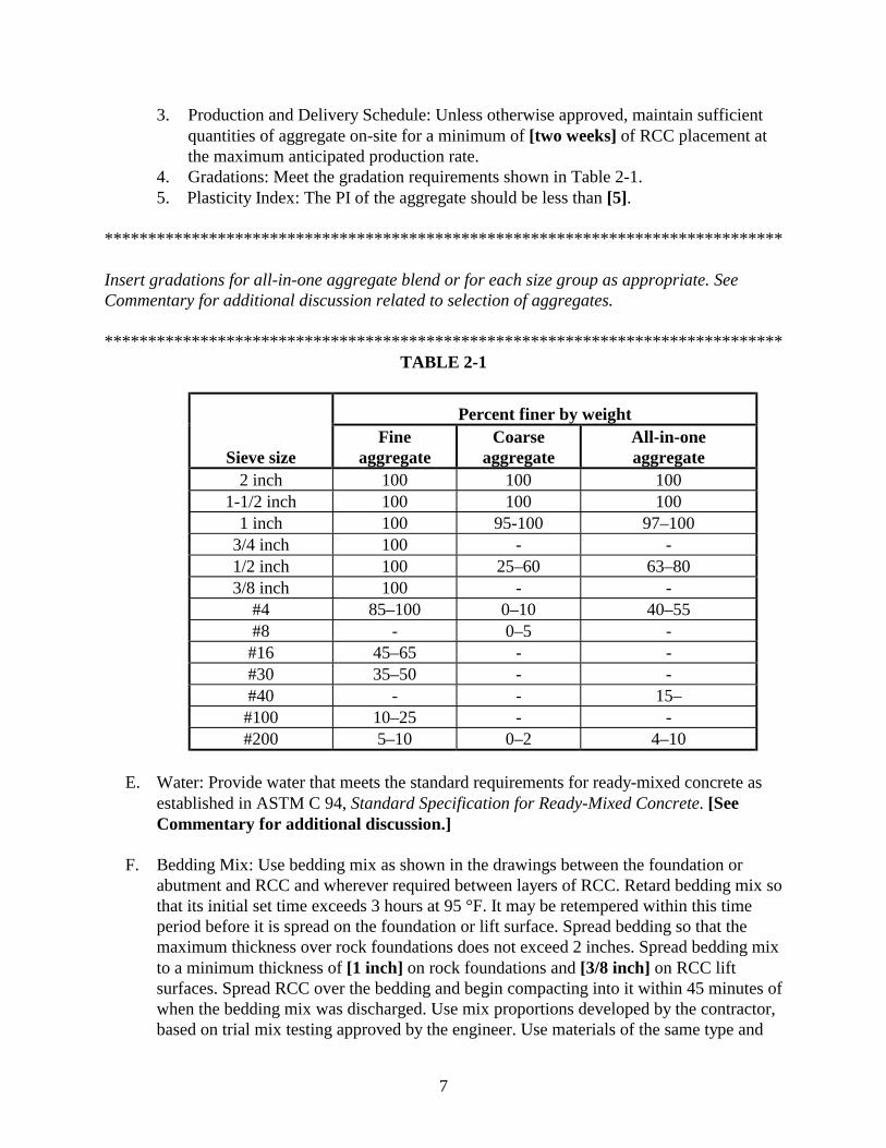
4. Gradations: Meet the gradation requirements shown in Table 2-1.5. Plasticity Index: The PI of the aggregate should be less than [5].
******************************************************************************
Insert gradations for all-in-one aggregate blend or for each size group as appropriate. SeeCommentary for additional discussion related to selection of aggregates.
******************************************************************************TABLE 2-1
Percent finer by weight
Sieve sizeFine
aggregateCoarse
aggregateAll-in-oneaggregate
2 inch 100 100 1001-1/2 inch 100 100 100
1 inch 100 95-100 97–1003/4 inch 100 - -1/2 inch 100 25–60 63–803/8 inch 100 - -
#4 85–100 0–10 40–55#8 - 0–5 -#16 45–65 - -#30 35–50 - -#40 - - 15–#100 10–25 - -#200 5–10 0–2 4–10
E. Water: Provide water that meets the standard requirements for ready-mixed concrete asestablished in ASTM C 94, Standard Specification for Ready-Mixed Concrete. [SeeCommentary for additional discussion.]
F. Bedding Mix: Use bedding mix as shown in the drawings between the foundation orabutment and RCC and wherever required between layers of RCC. Retard bedding mix sothat its initial set time exceeds 3 hours at 95 °F. It may be retempered within this timeperiod before it is spread on the foundation or lift surface. Spread bedding so that themaximum thickness over rock foundations does not exceed 2 inches. Spread bedding mixto a minimum thickness of [1 inch] on rock foundations and [3/8 inch] on RCC liftsurfaces. Spread RCC over the bedding and begin compacting into it within 45 minutes ofwhen the bedding mix was discharged. Use mix proportions developed by the contractor,based on trial mix testing approved by the engineer. Use materials of the same type and
8
from the same source as those used for the trial-mix testing. Proportion the bedding mixwithin the following general guidelines:
Slump (placed on RCC) ............................................................5 to 9 inchesMaximum aggregate size............................................................... [3/8 inch]Minus 200 material (aggregate)...............................................2% maximumWater reducing admixture................................................... may be requiredDesign strength (28 day) ...............................................................[2500 psi]Retarder ....................... as required to achieve the required delayed set time
Admixtures may be introduced into the mix to maintain its workability. Proportion themix to be very workable and to minimize segregation. Batch bedding mix either on-site oroffsite and transport to the lift surface by crane and bucket, transit truck mixer, pump, orother methods approved by the engineer. Do not use conveyor delivery unless it can bedemonstrated that the mix can be transported on the conveyor without any segregation.Pozzolan may be substituted for cement, up to a maximum of 30% by volume, providedthat all specification requirements are met.
******************************************************************************
Minimum thickness is the same as the MSA but not less than 3/8 inch. The design strength of thebedding mix must equal or exceed the design strength of the RCC.
******************************************************************************
G. Chemical Admixtures: Provide water reducing agent and retarding admixture thatconforms to ASTM C 494, type D, and water reducing admixture that conforms to type Arequirements. Provide dose rates in accordance with the approved mix design and mix asrecommended by the manufacturer. [See Commentary for additional discussion.]
******************************************************************************
Insert requirements for any other materials special to your project.
******************************************************************************
H. Joint Materials: Provide and install joint materials in accordance with Section 03250.
******************************************************************************
Not required if joints are not included in design.
******************************************************************************
9
2.02 MIX DESIGN(S)
A. General: Roller-compacted concrete mix proportions will be determined by the engineer.
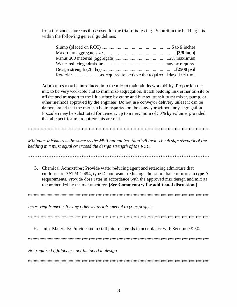
B. Mix Proportions: The anticipated RCC mix design(s) are approximated in Table 2-2based on preliminary evaluation of potential aggregate, cement, and pozzolan sources(weights are based on saturated surface-dry aggregate). The final mix design(s) will bedetermined from testing performed by the engineer using representative materialsprovided by the contractor.
TABLE 2-2
Weight in pounds per cubic yardAggregate
Mix Cement Pozzolan Free water Fine Coarse All-in-oneAB
******************************************************************************
Insert estimated mix proportions as appropriate. Specify all-in-one aggregate proportions orindividual fine and coarse aggregate proportions.
******************************************************************************
C. Mix Adjustments: Adjust mix water content based on continuous routine monitoring toobtain optimum compaction during all weather conditions. Do not adjust cement,pozzolan, or aggregate contents without written approval or direction from the engineer.Cement and pozzolan adjustments will only be permitted or directed after development ofsufficient supporting test results indicating justification for the adjustment.
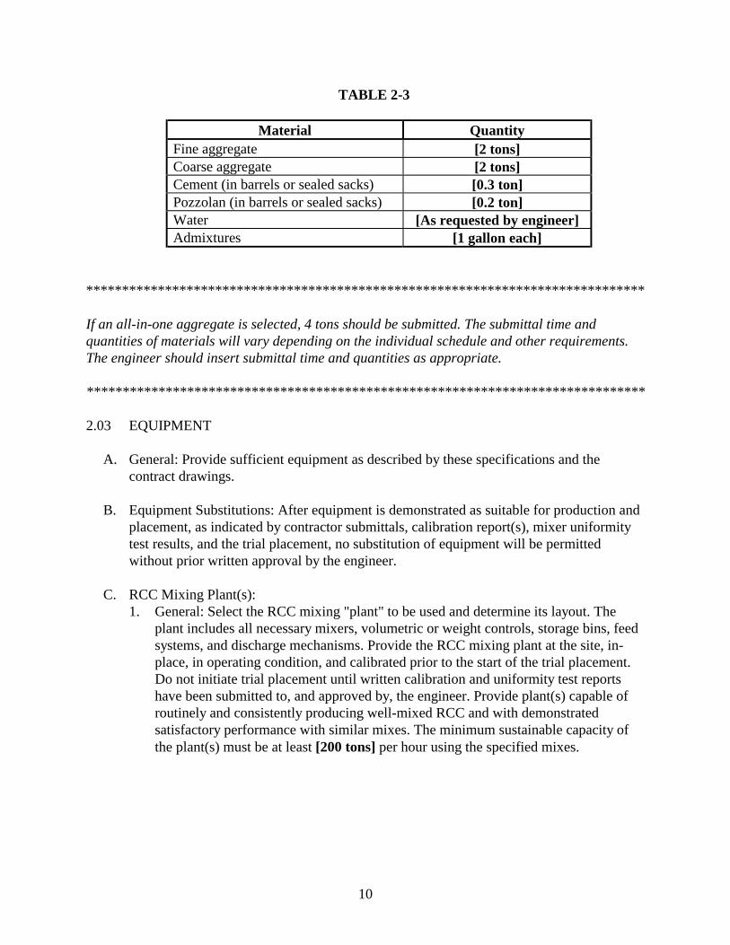
D. Material Samples: Submit representative production samples of cement, pozzolan, andadmixtures to the engineer's laboratory [provide address, phone number, and contact]within [30 calendar days] following Notice-to-Proceed. Submit samples that arerepresentative of those proposed for the project and include manufacturer's test reportsindicating compliance with applicable specification requirements and showing allchemical and physical properties. Identify all materials with labels and/or tags asappropriate. Provide minimum quantities of materials as shown in Table 2-3.
10
TABLE 2-3
Material QuantityFine aggregate [2 tons]Coarse aggregate [2 tons]Cement (in barrels or sealed sacks) [0.3 ton]Pozzolan (in barrels or sealed sacks) [0.2 ton]Water [As requested by engineer]Admixtures [1 gallon each]
******************************************************************************
If an all-in-one aggregate is selected, 4 tons should be submitted. The submittal time andquantities of materials will vary depending on the individual schedule and other requirements.The engineer should insert submittal time and quantities as appropriate.
******************************************************************************
2.03 EQUIPMENT
A. General: Provide sufficient equipment as described by these specifications and thecontract drawings.
B. Equipment Substitutions: After equipment is demonstrated as suitable for production andplacement, as indicated by contractor submittals, calibration report(s), mixer uniformitytest results, and the trial placement, no substitution of equipment will be permittedwithout prior written approval by the engineer.
C. RCC Mixing Plant(s):1. General: Select the RCC mixing "plant" to be used and determine its layout. The
plant includes all necessary mixers, volumetric or weight controls, storage bins, feedsystems, and discharge mechanisms. Provide the RCC mixing plant at the site, in-place, in operating condition, and calibrated prior to the start of the trial placement.Do not initiate trial placement until written calibration and uniformity test reportshave been submitted to, and approved by, the engineer. Provide plant(s) capable ofroutinely and consistently producing well-mixed RCC and with demonstratedsatisfactory performance with similar mixes. The minimum sustainable capacity ofthe plant(s) must be at least [200 tons] per hour using the specified mixes.
11
******************************************************************************
See Commentary on mixing plant capacity requirements.
******************************************************************************
2. Description: Provide twin shaft paddle-type continuous mix or batch-type "pugmill"plant(s). Do not charge mixers in excess of the capacity recommended by themanufacturer for RCC. Provide mixers capable of combining the materials into auniform mixture and capable of discharging this mixture without segregation. Batch-type drum mixers may also be submitted for approval provided that they have provensatisfactory with similar mixes and can meet the required production rates. It mustalso be demonstrated that they have low maintenance, available spare parts, and theability to meet variability requirements. Traditional drum-type mixers mustdemonstrate that the specific plant consistently meets uniformity requirementsspecified herein. The plant’s transfer systems must be capable of charging anddischarging the constituents and the mixed product without bridging or choking.
3. Mixing Time:a. Batch-Type Drum Mixers: The mimimum mix retention time should be 90
seconds. Prior to the test section, mixer uniformity tests, performed inaccordance with Section 2.03C must be performed. Longer mixing times willbe required if needed to meet the tolerances in Table 2-4.
b. Continuous Mixing Pugmills: The minimum mixing time for continuousmixing pugmills or batch-type pugmills is 15 seconds. If the plant proposed bythe contractor has successfully mixed RCC of similar proportions and theplant operator has experience both with RCC mixing and the proposed plant,no mixer uniformity tests are required unless the engineer determines there areproblems with the consistency of the RCC mix. At the direction of theengineer, perform mixer uniformity tests. If the plant fails to meet thetolerances shown in Table 2-4, increase the mixing time to achievecompliance with Table 2-4 or use a new plant. Regardless of the type ofmixing plant used, if it fails a uniformity test, no production work can begin orresume until a satisfactory test is performed.
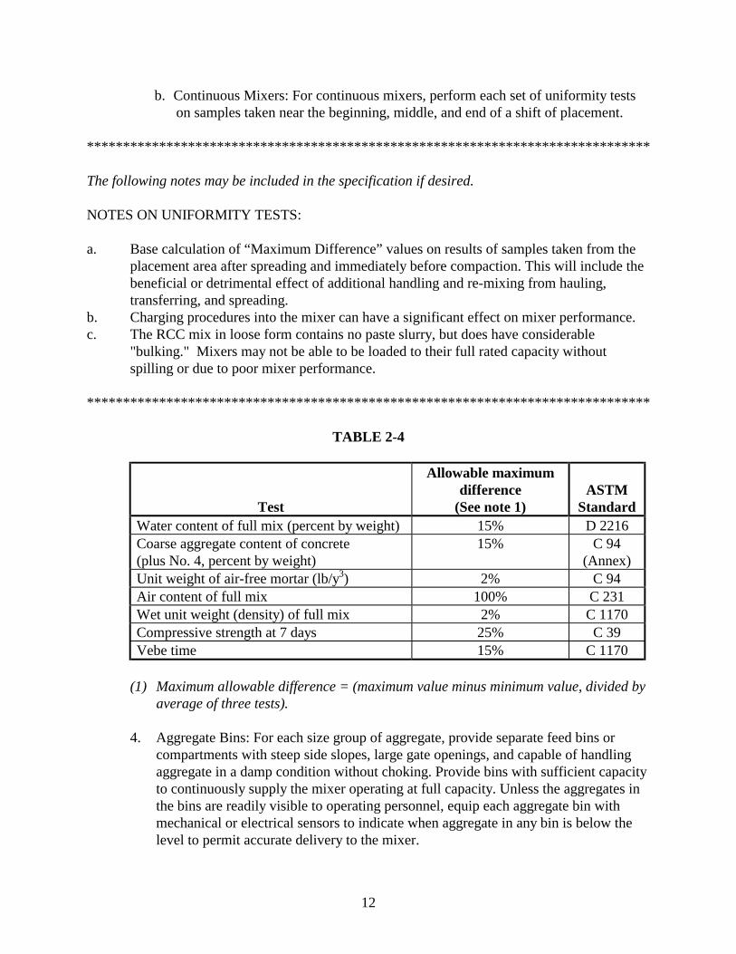
4. Uniformity Tests: Where the proposed mixing plant does not have a record ofsuccessfully mixing RCC similar to that required for the project, perform a set ofthree mixer uniformity tests. The tests required for each set of uniformity tests isshown in Table 2-4. Take all samples for testing from the placement area followingspreading of the material. A mixing plan will be considered acceptable provided thattolerances for 6 out of the 7 tests listed in Table 2-4 are met.
a. Batch-Type Mixers: For batch-type mixers, perform each set of uniformitytests on separate batches of roller-compacted concrete taken near thebeginning, middle, and end of a shift of placement.
12
b. Continuous Mixers: For continuous mixers, perform each set of uniformity testson samples taken near the beginning, middle, and end of a shift of placement.
******************************************************************************
The following notes may be included in the specification if desired.
NOTES ON UNIFORMITY TESTS:
a. Base calculation of “Maximum Difference” values on results of samples taken from theplacement area after spreading and immediately before compaction. This will include thebeneficial or detrimental effect of additional handling and re-mixing from hauling,transferring, and spreading.
b. Charging procedures into the mixer can have a significant effect on mixer performance.c. The RCC mix in loose form contains no paste slurry, but does have considerable
"bulking." Mixers may not be able to be loaded to their full rated capacity withoutspilling or due to poor mixer performance.
******************************************************************************
TABLE 2-4
Test
Allowable maximumdifference
(See note 1)ASTM
StandardWater content of full mix (percent by weight) 15% D 2216Coarse aggregate content of concrete(plus No. 4, percent by weight)
15% C 94(Annex)
Unit weight of air-free mortar (lb/y3) 2% C 94Air content of full mix 100% C 231Wet unit weight (density) of full mix 2% C 1170Compressive strength at 7 days 25% C 39Vebe time 15% C 1170
(1) Maximum allowable difference = (maximum value minus minimum value, divided byaverage of three tests).
4. Aggregate Bins: For each size group of aggregate, provide separate feed bins orcompartments with steep side slopes, large gate openings, and capable of handlingaggregate in a damp condition without choking. Provide bins with sufficient capacityto continuously supply the mixer operating at full capacity. Unless the aggregates inthe bins are readily visible to operating personnel, equip each aggregate bin withmechanical or electrical sensors to indicate when aggregate in any bin is below thelevel to permit accurate delivery to the mixer.
13
5. Cement and Pozzolan Silos: Provide individual silos for bulk portland cement andpozzolan (if used) with ample size and so constructed that the various materials willremain separate under all working conditions. Separate all compartments containingcement (and pozzolan) from each other by a free draining air space. Clearly markcement and pozzolan silos with signs to indicate the material contained in each silo.
6. Water Dispenser: Provide a water dispenser that is capable of dispensing the mixwater within the specified requirements. Provide piping, valves, and othercomponents that are free from leakage for delivering water to the mixer(s). Watermay be weighed or metered by an in-line volumetrically activated flow meter. Thevalve must be capable of gradual adjustment during the mixing process tocompensate for varying moisture contents in the aggregates. Use valves that areautomatically controlled and close if cement, pozzolan, or aggregate stops enteringthe mixer at the required rate. This control may be bypassed for cleaning operation.
7. Sampling Facilities: Provide suitable facilities and labor for obtaining representativesamples of materials as they enter the mixer, are discharged from the mixer, aredischarged from gob hoppers, and from the placement after spreading but beforecompacting. Furnish all necessary platforms and equipment for obtaining samples.
D. Conveyors: Design and/or provide conveyors and transfer components for lowmaintenance, continuous operation with clean return belt surfaces and withoutsegregation or excessive loss of material. [Fit all belts with covers or shields to preventdrying by the wind and sun, and over-wetting from rain.]
******************************************************************************
For conveyors that result in limited exposure time on the belts or during placement in coolweather, the requirement for covers can be omitted.
******************************************************************************
E. Haul Vehicles: RCC may be hauled using trucks, large front-end loaders, or scrapers fromthe [plant discharge] [conveyor discharge] to various locations on the placement area.Tracked haul vehicles will not be permitted. Use bottom-dump haul vehicles, end-dumptrucks with special tailgates or drop control methods that demonstrate an ability to handledumping without excessive segregation, and/or front-end loaders. The haul vehicles mustbe free of deleterious materials including, but not limited to, oil, grease, loose,deteriorated, or dry RCC, and soil. The maximum free fall drop height from haulingvehicles is 5 feet.
F. Temporary Storage Containers: For continuous mixing plants provide a gob hopper orholding device for RCC temporarily accumulated after mixing and while waiting to beloaded into a hauling vehicle for transport. The gob hopper is not required if a totalconveyor system without haul vehicles is used.
14
G. Chutes and Drop Tubes: Unless specifically authorized in writing, chutes or uncontrolleddrops exceeding 5 feet will not be permitted.
H. Spreading Equipment: Provide equipment for spreading compatible with the capacity ofthe plant, delivery systems, and size of the work area. Equipment must be capable ofplacing the RCC in uniform lifts and without segregation.
******************************************************************************
Paving machines are acceptable if they can place the RCC to the specified thickness and tampingbars are used behind the screed. The suitability and acceptance will be based on the results ofthe test section.
******************************************************************************
I. Compaction Equipment:1. Primary Rollers: Provide single or double drum, self-propelled vibratory rollers that
transmit a dynamic impact to the surface through a smooth steel drum by means ofrevolving weights, eccentric shafts, or other equivalent methods. Use compactorswith gross weights of not less than 21,000 lb, minimum dynamic force of at least 475lb per inch of drum width at the operating frequency used during construction,vibrating frequency of at least 1500 cpm (cycles per minute), drum diameter between4 and 6 feet, drum width of 5 to 8, and engine horsepower of at least 125. Within therange of operational capability of the equipment, variations to the frequency andspeed of operation that result in maximum density at the fastest production rate willbe allowed. Any other compaction equipment proposed must demonstrate that it iscapable of compacting the RCC full depth to the specified density prior to RCCproduction. Provide at least one fully operable, self-propelled vibratory roller on theplacement area at all times during production placement. [Provide standbyreplacement equipment available for functional operation on the placementwithin 30 minutes.]
******************************************************************************
The requirement for standby replacement equipment may be omitted unless there is a seriousquality concern resulting from a project shutdown.
******************************************************************************
2. Small Vibratory Rollers: Use small vibratory rollers that can operate within a fewinches of a vertical face to compact the RCC adjacent to formwork, precast panels,conventional concrete structures, abutment slopes, and at other areas where the largevibratory rollers specified above cannot maneuver. Provide rollers with a dynamicforce of at least 150 lb/in. of drum width for each drum of a double drum unit and atleast 300 lb/in. of drum width for a single drum unit. Provide at least one fully
15
operable, small roller at the site during RCC placement. [Provide standbyreplacement equipment available for functional operation on the placementwithin 30 minutes.]
3. Tampers, Plates, and Rammers: Provide tampers, plates, and rammers that develop aforce per blow of at least 3500 lb per square foot. Maintain at least two tampers,plates, or rammers in good operating condition at the site during RCC placement.
PART 3 - EXECUTION
3.01 SCHEDULE AND WEATHER RESTRICTIONS
A. Schedule: It is the intent of this specification to construct the RCC in a continuous operationto the extent practical. Schedule RCC placement [6 days] per week [one 10-hour] shift perday from the start of placement until completion. Begin placement no later than [April 15]and complete by [June 15] of the [same year].
******************************************************************************
Insert placement time limits if required to limit peak temperatures and/or if the owner or localmunicipality has schedule or regulatory requirements that affect the contractor’s productionschedule. Insert the appropriate dates, paying attention to local climate conditions. Forarmoring and overtopping projects, temperature sensitivity is generally not a major concern.The RCC placement window should be wide enough to afford the contractor flexibility. Enoughtime must be allowed after the Notice-to-Proceed to complete mix designs, prepare foundations,dewater, etc., before the RCC placement window is specified.
******************************************************************************
B. Cold Weather Concreting: When ambient temperatures fall below 35 °F, institute coldweather concreting procedures as described in Paragraph 3.12.
C. Hot Weather Concreting: Suspend RCC placement when the temperature of the RCCmeasured at the point of placement exceeds the limits specified in Paragraph 3.08, or if acombination of high ambient temperatures and wind dries the uncompacted RCC,preventing adequate compaction.
******************************************************************************
In addition to the placement temperature limits specified in Paragraph 3.08, the engineer mayalso specify a maximum air temperature. However, under most circumstances this is notrequired.
******************************************************************************
16
D. Placing During Precipitation: Do not place RCC during heavy rains (more than 0.2 inchper hour or 0.03 inch in 6 minutes as defined by the U.S. Weather Bureau Glossary ofMeteorology). Suspend production when free surface water begins to accumulate on thecompacted RCC, when excessive pumping, tracking, or other unacceptable damagebegins to develop, or when, in the opinion of the engineer, rain is adversely affecting anyaspect of quality. Remove any uncompacted RCC exposed to precipitation that, in theopinion of the engineer, makes it unsuitable.
3.02 FOUNDATION PREPARATION
A. General: Prior to placing roller-compacted concrete on the foundation and againstabutments, clean, fill with dental concrete (if necessary), shape (if necessary), and prepareexposed rock surfaces. Do not cover any foundation, embankment slope, or abutment areawith any concrete or bedding mix until the area has been approved by the engineer. Placebedding mix as described in Section 3.02F between the rock foundation or hardenedconventional concrete and RCC mixes, except where shown otherwise. No RCC is to beplaced in water or on soft foundation material.
****************************************************************************
For most projects, the engineer should include a separate specification that covers foundationpreparation requirements in more detail.
****************************************************************************
B. Dewatering:1. Groundwater Control: During the period of RCC preparation and placement,
maintain foundations in a dewatered condition. For earth foundation surfaces, installdewatering systems that maintain ground water levels a minimum of 3 feet below thefinal foundation grade. For rock foundation surfaces, install dewatering systems thatprevent ponding and water flowing over rock surfaces.
2. Surface Water Control: Prior to preparing the area for RCC placement, installfacilities to divert surface water from the work area. Maintain facilities until all RCCplacement and curing are complete.
C. Shaping and Filling Rock Surfaces: Fill depressions as directed by the engineer withconventional dental concrete or roller-compacted concrete. Dental concrete placementareas will be decided by the engineer depending on area access for equipment andthickness of lifts. Dental concrete may require rough face forming, as shown on thedrawings. Continuously moist cure dental concrete for [7 days] or until covered withadditional RCC.
D. Preparation of Earth Slopes and Foundations: Prior to placement of RCC on or againstany earth foundation or slope, remove all organics, soft or loose material. Loosen theremaining fill surface by scarifying, plowing, disking, or harrowing to a depth of 4 to 6
17
inches. Fill all depressions with soil of the same type as the surrounding soil. Adjust themoisture content of the surface as specified for the soil class and compact the foundationor slope to a minimum of [95%] Standard Proctor. If allowed to dry, moisten earth slopesand foundations just prior to placing RCC.
******************************************************************************
Note: For most projects a specification section should be included that describes requirementsfor testing, placement, compaction, and acceptance of fill materials. For steep slopes greaterthan 2:1V scarifying the slope will not be necessary.
******************************************************************************
E. Final Cleanup: Prior to placing any concrete or bedding mix, clean the surface to removeloose, unkeyed, and deteriorated rock; all mud, silt accumulations, vegetation, grease andspilled oils; frozen materials, standing water, accumulations of gravels, sands and looserock fragments; laitance that may have accumulated on concrete surfaces; and any otherdetrimental material. It is expected that most of this can be accomplished with airblowing, high-volume water washing, and/or air/water jetting using equipment normallydesigned for this purpose and used in large scale foundation cleanups. High performancevacuum systems have also been effective for low areas or pockets in the foundation wherewater, soil and rock accumulates. A clean sound surface is required. Maintain surfacesupon which RCC or any bedding mix is placed in a damp condition and at a surfacetemperature in excess of 35 °F. Provide adequate equipment for air, air/water, and/orpressure water washing of the foundation.
3.03 PLANT CALIBRATION AND TESTING
A. Initial Plant Calibration: Certify scales and calibrate plant in accordance with plantmanufacturer’s written instructions. Prepare and submit certifications and/or calibrationreport in accordance with requirements of Paragraph 1.04.
B. Mixer Uniformity Testing: Perform mixer uniformity testing if required by Section2.3.C.3 prior to trial placement to confirm that the mixer and handling and placingprocedures meet the specification requirements contained in Table 2-4 and to determinethe appropriate mixing time. Placement of RCC in the permanent work will not bepermitted until the results of mixer uniformity testing, if required, are submitted to andapproved,by the engineer.
C. Recalibration Interval: Perform recalibration of the plant following each [30 shifts] or[5,000 cubic yards] of placement or when quality control testing indicates a potentialproblem.
18
3.04 AGGREGATE PRODUCTION, DELIVERY, AND HANDLING
A. General: The requirements of Paragraph 3.04 B through C also applies when RCC isproduced off-site and hauled to the project site.
B. Aggregate Production: Operate the aggregate production plant in an efficient manner toachieve and maintain an adequate level of productivity. Ensure that the final aggregateproduct is consistent and free from contamination by organic material, overburden, orother foreign materials.
******************************************************************************
The above paragraph and other references to on-site aggregate production may be omitted ifaggregates are purchased from a commercial supplier.
******************************************************************************
C. Environmental Controls:1. Stormwater Control: Implement work to conform to Best Management Practices for
control of site runoff and stormwater pollution for the work area that encompassesthe aggregate production plant, stockpiles, and related construction site areas.
2. Pollutant Control: Maintain aggregate plant areas in a clean orderly condition, freefrom spilled fuel, lubricant, coolant, or other potential pollutants. Maintain materialhandling areas to reduce potential for pollutants to enter stormwater runoff. Institutespecial precautions to prevent and to clean up spills of any material that mightcontaminate stormwater runoff.
****************************************************************************
A separate specification covering detailed requirements for environmental controls should beincluded in the bid documents.
****************************************************************************
D. Delivery: 1. Compliance with Regulations: The contractor’s responsibility includes ascertaining
and compliance with all state laws and regulations regarding haul vehicle weightlimits and other restrictions as they relate to haul vehicles on public roads. Where thepoint of ingress or egress is connected to a paved public road, provide a stabilizedconstruction entrance adjacent to the paved area to minimize the amount of mudtransported onto the paved area. Maintain the entrance pad and top dress withaggregate as required.
19
2. Delivery Route: Deliver aggregates using route(s) identified in the approved deliveryplan.
3. Maintenance of Roads: Promptly remove, to the satisfaction of the engineer and thehaul route’s jurisdictional authorities, any soil, aggregate, or other debris depositedon roads or adjacent areas as a result of the contractor’s activities associated with thework to be performed under this contract. If the contractor fails to clean a roadsurface and adjacent areas in a timely manner, or fails to clean the road surface andadjacent areas to the satisfaction of the owner of the road, the owner of the road orthe owner has the right to perform the corrective work and charge the contractor forthe cost incurred. If the contractor fails to pay the charges, said charges will bededucted by the owner from the contract bid price. [Perform a pre-haul survey thatdocuments the condition of the haul route prior to initiation of hauling.]
******************************************************************************
Include the above requirement for a pre-haul route survey in cases where substantial hauling isrequired or where damage or claims of damage might occur.
******************************************************************************
Notify the engineer as soon as any damage or deterioration to the road(s) occur that islikely to require remedial work.
3. Delivery Schedule: Within 14 days after Award of Contract, prepare and submit tothe engineer for approval a production and delivery schedule for the RCC aggregates.Limit delivery times to between [6:00 a.m. to 6:00 p.m., Monday throughSaturday]. [Unless otherwise permitted by the owner, no Sunday delivery willbe permitted. Requests for delivering RCC aggregates on Sunday must besubmitted to the owner for approval.]
******************************************************************************
Insert delivery days and hours as appropriate for the local municipality and requirements of theowner’s schedule. Depending on the difficulty of the project and the required RCC placementschedule, extended times for aggregate delivery may be necessary.
******************************************************************************
E. Stockpiling Procedures: Stockpile aggregate at the project site within the boundariesdesignated on the plans. Establish precise limits of the piles as necessary to accomplishthe work. Use separators, if necessary, such as timbers or boards between adjacentstockpiles to prevent contamination and intermixing between the stockpiles.
Prepare the lane and the base of the aggregate stockpile by removing all organic material,flattening the area, filling any major depressions, and sloping the surface of the stockpile
20
bases and the lane area to drain. [Provide a base of free draining gravel or crushedrock, or allow for a sacrificial layer of material within the stockpile area. If used, thebase material may have a maximum size up to 4 inches, not more than 10% passingthe 3/4-inch sieve, and not more than 2% passing the No. 50 sieve.]
******************************************************************************
In dry climates, a free draining stockpile base may be unnecessary. In these cases, the aboverequirement may be omitted.
******************************************************************************
Construct stockpiles by an approved method that reliably and consistently stores theaggregates and later allows their withdrawal from the stockpiles without contamination orsegregation. Provide a system that permits intermixing or blending of aggregates as theyare delivered and spread in the stockpiles.
E. Moisture Conditioning: If aggregate evaporative cooling is utilized, or if products aresufficiently dry to require moisture conditioning, continuously mist aggregates duringstockpiling to a saturated surface-dry (SSD) condition. Use sprinklers or fog spray typeand do not apply pressurized water directly into stockpile. Exercise caution duringaggregate stockpile misting to prevent washing of fine material.
F. Stockpile Withdrawal: Withdraw aggregates from the stockpiles using conveyors, faceloading with front-end loaders, or a combination of conveyors and face loading.Regardless of the method employed, withdraw materials that are representative of theentire stockpile, both in terms of gradation and moisture content. Blend any obviouslysegregated material with other material in a manner that will result in a gradation thatmeets the specifications. If the material cannot be suitably blended, separate it from thestockpile and use for other non-critical purposes, or waste the material.
******************************************************************************
Note: Face loading with front-end loaders is usually sufficient for the majority of embankmentarmoring and spillway projects.
******************************************************************************
3.05 TRIAL PLACEMENT
A. Purpose: The contractor should anticipate that at least [one full day] may be required tocomplete the goals of the trial placement. The contractor is encouraged to expand the trialplacement as necessary to demonstrate his ability to meet the specifications prior toproceeding with production placement.
21
******************************************************************************
Two or more days are sometimes used for the test section to simulate cold joints, cold jointtreatments, or other items that require an extended waiting period.******************************************************************************
B. Location: Construct the trial placement at a designated on-site location and in accordancewith the details shown on the drawings.
******************************************************************************
Sometimes the test section can be a part of the permanent structure if located in a non-criticalarea and the RCC properties meet the specifications.
******************************************************************************
C. Equipment and Placing Procedures: Demonstrate during the trial placement the intendedconstruction techniques and materials to be used in construction of the structure. Tasks tobe included are [facing elements], [lift-surface cleaning], [compaction], [densitytesting], [cold joints], [bedding-mix placement], and [forming and/or shaping ofsteps and training walls]. The supervisory and key craft personnel intended to performthe production placement must be involved in construction of the trial placement. Do notinitiate the trial placement until the plant and all equipment required for delivery andplacement of RCC are operational and fully calibrated. Perform mixer uniformity testing,if required by Section 2.03.C, prior to initiating trial placement. Trial placement for thetest section will not be permitted until the results on the uniformity testing, if required bySection 2.03.C, are provided to the engineer in writing and such test results demonstratethat the plant meets the specification requirements. Place a minimum of [100 cubic yardsand three 12-inch-thick lifts] [20 feet wide by 50 feet long with three lifts] in the trialplacement. Place bedding mix, if required, on a minimum of two lifts as shown on thedrawings. Anticipate and allow for numerous stops/restarts during the trial placement sothat the engineer may perform testing of the RCC. Demonstrate various spreading andcompaction procedures including, but not limited to, various equipment types, andnumbers of passes. Construct the trial placement just prior to production placement ofRCC.
******************************************************************************
Place any other items to be demonstrated at the test section in this paragraph.
******************************************************************************
D. Testing and Quality Control: Prior to initiating the trial placement, perform testing of theaggregates in accordance with the requirements of Paragraph 3.16 to demonstrate thatspecification requirements are met. Perform all other tests and quality control measures
22
identified in Paragraph 3.16 during the trial placement. In addition, the engineer willperform his own tests and inspections and the contractor should anticipate interruptions tohis work to accommodate such tests and inspections. Allow [7 days] from the completionof the trial section until production can begin so the engineer can perform his evaluationof the test section.
******************************************************************************
If the engineer does not plan on any strength testing of the RCC in the test section, the [7 day]requirement can be eliminated.
******************************************************************************
E. Critique: The engineer and contractor will closely monitor activities during constructionof the trial placement and provide an informal critique and review session for allinvolved, including supervision, inspection, engineering, and craft personnel, prior toRCC placement in the structure.
3.06 MIXING
A. Cement and Aggregate Feed: Feed cement and aggregates uniformly, continuously, andsimultaneously, at the appropriate ratios for the mix design specified, into the mixer bybelt or other acceptable method. Feed controls may be by volume or weight. Aggregatefeed may be accomplished by a single belt from each stockpile or from feed bins of thevarious size groups through openings at the bottom of the feed bins. Provide eachopening in aggregate feeders with a gate that can be locked at the necessary opening sizeto provide the correct feed rate. Keep return side of all belts clean. Keep bins sufficientlyfull to allow a uniform flow of aggregate at an essentially constant rate. Particularattention may be needed to guarantee a continuous flow of the fine aggregate if it is verydamp and is graded towards the fine side of the specified gradation band. Feed cement(and pozzolan) continuously in a manner that can be controlled by adjusting the beltspeed or feed rate. Provide special attention to the cement (and pozzolan) feed equipmentso that it consistently and uniformly delivers materials even at low (100 lb/yd3 or less)dosage rates. Use feeds capable of gradual adjustment while in operation. Usecontinuously correcting automated gate openings and/or belt-feed rates by electronicfeedback of weight sensor units on the belts if operation without them cannot provide theaccuracy, consistency, and quality required by these specifications.
B. Operation: The intent is to operate continuous pugmills in a continuous manner at one setof feed rates with a minimum number of shutdowns and startups during RCC productionplacing. Calibrate and operate the plant so that all materials simultaneously begin feedinginto the mixer at the correct rates when the mixer is started, and all materialssimultaneously stop feeding into the mixer when it is stopped. No lag or lead timebetween materials will be allowed at the point where they enter the mixer. After materialfeeds are shut down, discharge all remaining material in the mixer. The initial RCC
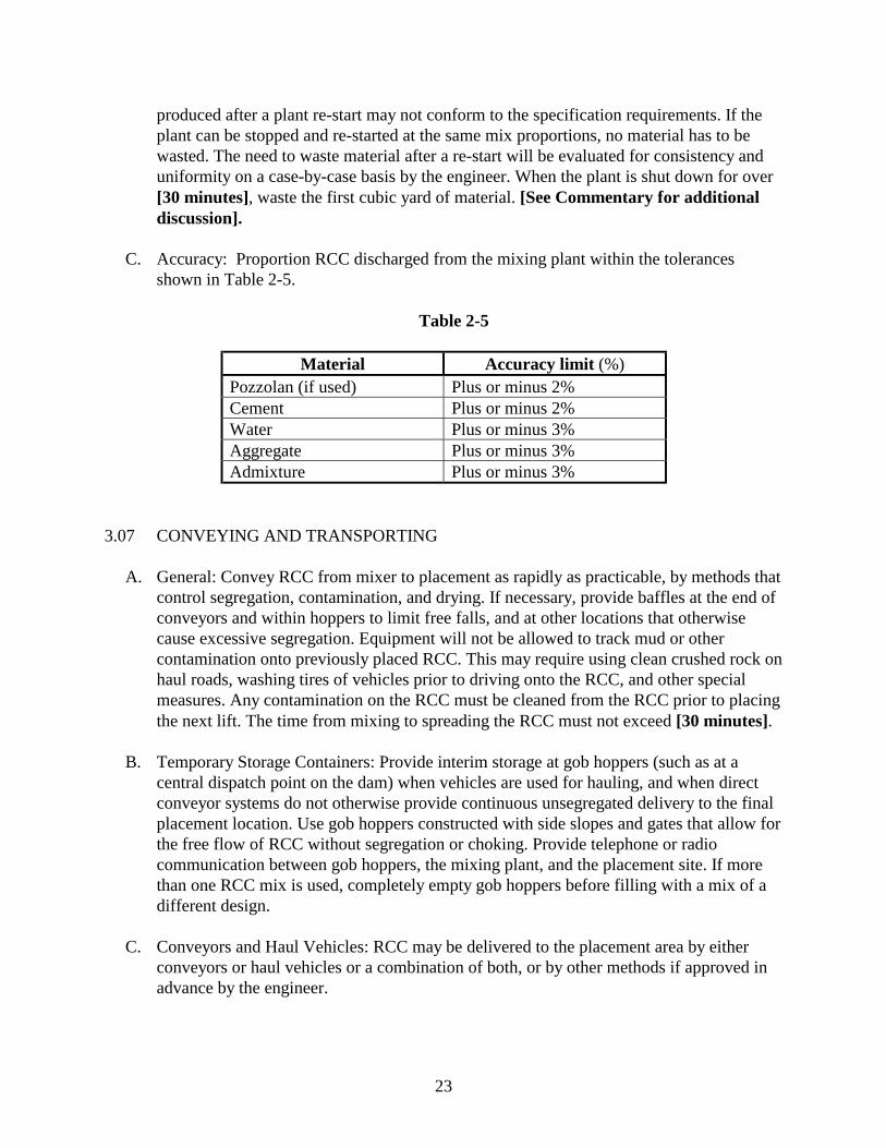
23
produced after a plant re-start may not conform to the specification requirements. If theplant can be stopped and re-started at the same mix proportions, no material has to bewasted. The need to waste material after a re-start will be evaluated for consistency anduniformity on a case-by-case basis by the engineer. When the plant is shut down for over[30 minutes], waste the first cubic yard of material. [See Commentary for additionaldiscussion].
C. Accuracy: Proportion RCC discharged from the mixing plant within the tolerancesshown in Table 2-5.
Table 2-5
Material Accuracy limit (%)Pozzolan (if used) Plus or minus 2%Cement Plus or minus 2%Water Plus or minus 3%Aggregate Plus or minus 3%Admixture Plus or minus 3%
3.07 CONVEYING AND TRANSPORTING
A. General: Convey RCC from mixer to placement as rapidly as practicable, by methods thatcontrol segregation, contamination, and drying. If necessary, provide baffles at the end ofconveyors and within hoppers to limit free falls, and at other locations that otherwisecause excessive segregation. Equipment will not be allowed to track mud or othercontamination onto previously placed RCC. This may require using clean crushed rock onhaul roads, washing tires of vehicles prior to driving onto the RCC, and other specialmeasures. Any contamination on the RCC must be cleaned from the RCC prior to placingthe next lift. The time from mixing to spreading the RCC must not exceed [30 minutes].
B. Temporary Storage Containers: Provide interim storage at gob hoppers (such as at acentral dispatch point on the dam) when vehicles are used for hauling, and when directconveyor systems do not otherwise provide continuous unsegregated delivery to the finalplacement location. Use gob hoppers constructed with side slopes and gates that allow forthe free flow of RCC without segregation or choking. Provide telephone or radiocommunication between gob hoppers, the mixing plant, and the placement site. If morethan one RCC mix is used, completely empty gob hoppers before filling with a mix of adifferent design.
C. Conveyors and Haul Vehicles: RCC may be delivered to the placement area by eitherconveyors or haul vehicles or a combination of both, or by other methods if approved inadvance by the engineer.
24
*****************************************************************************
Note: Specific project requirements may dictate that one particular delivery method is preferredbecause of site access, weather, or quality requirement. In that case, the design engineer mayprohibit one of the delivery methods specified below.
******************************************************************************
1. Haul Vehicle Delivery: Haul vehicles will not be permitted to travel on and off anylift surface without precautions to prevent contamination of the RCC. Remove byhand or reblend during spreading any segregation that results from using haulvehicles. Maintain hauling vehicles in good operating condition and prevent oil,grease, or other visible and obvious contamination to spill or drip onto the RCC.Operate haul vehicles in a manner that precludes tight turns, sudden stops, or otherprocedures that damage previously compacted RCC. If a surface is damaged byvehicle operation (tight turns, oil spills, etc.), clean the damaged surface or removethe damaged material. Haul vehicles must meet the requirement of Section 2.03.E.
2. Conveyor Delivery: Conveyor belt delivery is required for all RCC delivered fromthe concrete plant to the point of final placement. The only RCC that will beconsidered for truck delivery to the placement area or active lift surface will be anytrial placement or practice areas. Operate belts at speeds that meet productionrequirements and do not segregate materials.
******************************************************************************
Note: Experience has shown that conventional end dumps have a tendency to cause segregationat the edge of the deposited material. Drier mixes, mixes with a low sand content, and mixes withmaximum size aggregate larger than 1-1/2 inch have the greatest tendency for segregation. If thedesigner plans to use a mix with these characteristics, consideration should be given torestricting use of end-dump trucks.
******************************************************************************
3.08 PLACING AND SPREADING
A. General: The contractor is cautioned to understand and apply applicable fall protectionrequirements to all work on the site. The contractor is responsible for all health and safetyrequirements at the site.
B. Temperature Restrictions: Do not place RCC when ambient temperatures drops below32 °F, unless the surface of the compacted RCC and the temperature of the RCC mixstays above 35 °F. In that case, placing of RCC during temporary periods will bepermitted if the ambient temperature remains above [25 °F]. If the ambient temperaturedrops below 32 °F or the surface of any RCC less than 7 days old drops to 35 °F, cover
25
the surface with heavy tarps, blankets, straw, or other acceptable temporary protectionuntil the ambient temperature rises above 35 °F. Remove RCC that is less than 7 days oldand is exposed to temperatures less than 32 °F.
Place all RCC at a material temperature of [80 °F] or less. The temperature will bemeasured at the point where the RCC is delivered to the lift surface. Introduction ofchilled water in the mix, cooling the coarse aggregate with chilled water, placement atnight, spraying the coarse aggregate stockpile with chilled water, cooling material byinjection with liquid nitrogen, or other approved measures will be required when thistemperature restriction cannot be met by normal placement procedures.
******************************************************************************
Note: Insert maximum placing temperatures as appropriate considering the annual averagetemperature at the site. Higher maximum RCC placing temperatures can be tolerated in warmerclimates. If conditions are such that the in-place temperature of the RCC is not a concern, thepreceding paragraph may be eliminated. However, experience has demonstrated that sometemperature controls are usually necessary to prevent unacceptable cracking of the RCC.
******************************************************************************
C. Layout of the Placement Area: It is the intent of this specification to raise the RCC atessentially the same level across its entire area. As nearly as is practical, expose no morethan two lift surfaces at one time. One additional layer may be exposed under specialcircumstances such as crossing conduits or other features. Maintain lift grade control byusing grade stakes and/or laser-guided equipment, or other surveying methods. Asplacement of a lift progresses keep the exposed edges "live" by progressively placing outfrom them. Whenever a cold joint at any edge of any lift occurs, locate it at least 10 feetfrom the location of other cold joints that may have previously occurred in the samedirection. Prepare the joint as required by Section 3.10 of these specifications for "coldjoints" prior to resumption of RCC placement.
D. Depositing: Deposit RCC at the location at which it is to be spread. Where haul vehicledelivery is used, depositing will generally be accomplished with a dump-spread actionwhile the vehicle is moving. When stationary end dumping is necessary, deposit thematerial on top of the fresh RCC layer being advanced, not on the previously compactedlayer. Do not place material in piles higher than 5 feet. For belt delivery, limit pile heightsand discharge from the belts in a manner that does not cause segregation. If trucks areused to deliver RCC, do not discharge material directly against any formwork. At isolatedor confined placement locations, the engineer may permit pushing the RCC up to [50feet] with spreading equipment, provided that segregation does not occur. Modifyoperations if excessive segregation is determined to be occurring by the engineer.
26
******************************************************************************
Note: Experience has shown that wet mixes with a high sand content and 1-1/2-inch maximumsize aggregate can be pushed 50 feet or more without noticeable segregation. The segregationpotential increases significantly for drier mixes, with lower sand contents and larger aggregate.The designer should consider the RCC mix when selecting an allowable limit for pushing RCC.
******************************************************************************
E. Lift Thickness: Unless another lift thickness is satisfactorily demonstrated and approvedduring the trial placement construction, place RCC in 12-inch lifts as measured aftercompaction. Do not place RCC in compacted lifts less than 4 inches thick.
F. Spreading: Within 10 minutes of deposition, knock down and spread the RCC pile usinga tracked dozer or other approved spreading equipment. Spread material so that it isplaced in unsegregated layers that will result in a compacted lift with a thickness ofapproximately [12 inches] and within the tolerances specified in Paragraph 3.15. WhereRCC is spread onto or into bedding mix, spread and compact the RCC mix within90 minutes of the time the bedding mix was batched, prior to the time that it begins to setor dry from exposure, and within 45 minutes of when the bedding mix was firstdeposited. Do not operate tracked spreading equipment on compacted RCC unless trackswith flat rubber pads are used or rubber mats are placed between the compacted surfaceand the dozer tracks. Remove any loose material resulting from operation of equipmenton compacted surfaces prior to placing the next lift. Have a front-end loader with operatoravailable to assist with depositing and spreading of material in confined areas, at irregularfoundation conditions, and at other locations as needed. Accomplish spreading in amanner that does not cause segregation. If large aggregate rolls or segregates to theoutside edge of a spread layer of RCC, reblend it into the RCC or remove it. Maintain allequipment in good operating condition so that it does not leak or drip oil, grease, or otherobvious visible contamination onto the RCC. Do not place concrete on a previous layerwhich is suspect and is being considered for testing, retesting, or rejection.
RCC may be placed with an approved paver. Adjust the paver and regulate the speed toprevent segregation. Do not exceed a paver speed of 10 feet per minute unless it can bedemonstrated to the satisfaction of the engineer that higher speeds do not cause problems.Operate the paver with a constant supply of RCC in the hopper.
******************************************************************************
Experience has shown that segregation may occur when the mix becomes drier than desiredand/or when care is not used during dumping and spreading. Large aggregate that rolls to theoutside edge of a spread layer can be picked up by laborers with flat shovels and broadcast overthe uncompacted surface in order to be compacted into the RCC without segregation.
******************************************************************************
27
3.09 COMPACTION
A. Determination of Optimum Compaction Density Value: The engineer will determine theoptimum compaction density value during the trial placement. The value will beestablished after evaluation of density results obtained with a nuclear density gauge andevaluation of the compaction characteristics for each mix design. Final evaluation ofdensity results for the determination of the optimum compaction density value will bemade only after all major field adjustments have been made and the mix design isconsidered to represent RCC that has suitable placement, spreading, and compactioncharacteristics, and provides the required strength and porosity values. Small fieldadjustments to the optimum compaction density value will be made throughoutconstruction based upon the running average density value. Such changes may be madebased on slight changes or long-term drift of density values resulting from field mixdesign adjustments.
******************************************************************************
See Commentary for method of determining optimum compaction density value.
******************************************************************************
B. Compaction: Within [45 minutes] of water being introduced at the mixing plant, compacteach 12-inch layer of RCC with a minimum of 4 passes of a self-propelled double drumor 8 passes of a self-propelled, single-drum vibratory compactor. (A round trip is 2passes). Use the largest size equipment specified below that is capable of physical andpractical operation in the area to be compacted. Use large width self-propelled vibratoryrollers in open areas with a minimum of 4 vibratory passes on each lift. Use small walk-behind vibratory rollers and/or hand-guided power tampers for compaction at theabutments and in any areas that cannot be reached with the drum of a large vibratoryroller. Do not operate rollers in the vibratory mode until they are moving. Maintain allcompaction equipment in good operating condition at all times and do not allow it to dripor spill oil or other obvious visible contamination onto the RCC. Break down, trim, andcompact the edge of all compacted layers against which adjacent RCC is not placedwithin [30 minutes] so that the edge is thoroughly compacted and does not contain loosesegregated aggregate. Spread and roll so that a flat surface results with minimum rollermarks from the edge of the drum, and so that the drum does not bridge over any of thesurface beneath the roller drum after the last pass. Operate rollers at speeds not exceeding160 feet per minute.
C. Acceptance: The running average of [5] consecutive in-place density tests should not beless than 98% of the optimum compaction density value, with no individual test less than96%. Determine the average wet density from the average of two readings taken with thegauge probe at a depth of 12 inches. If the two readings vary by more than 2%, repeat thedensity test. If it is demonstrated early in production that the two readings are consistently
28
within 2%, the two readings can be discontinued. Also measure densities with the gaugeprobe at 4 inches and 8 inches; however, these readings will not be used to compute theaverage density.
******************************************************************************
See Commentary for alternative methods of determining the required density.
******************************************************************************
D. Additional Compaction: If, after testing, the RCC does not meet the required density, itmay be compacted with additional roller passes, provided that the time limit in Paragraph3.07A has not been exceeded.
E. Removal of Material: If the time limit specified in Paragraph 3.07A has been exceededand the RCC has not achieved the required density, remove the RCC and replace at nocost to the owner. Clean the underlying surface and treat as a lift surface cold joint priorto replacing the removed RCC with new material.
F. Exposed Edge Compaction: Where lift edges are permanently exposed, compact orpurposely overbuild edges to allow for trimming back to well-compacted RCC, meetingthe design lines and grades. Edge compaction may be by excavator mounted vibratorycompaction plates, or other means approved during the trial placement construction.Trimming may be performed manually or with mechanical equipment.The minimumdensity of unformed edges must be 95%.
3.10 LIFT AND CONTRACTION JOINTS
A. General: It is the intent of this specification to place the entire roller-compacted concretemass with sufficient continuity so that it hardens and acts as one monolithic block(between contraction joints) without discontinuous joints or potential planes ofseparation. The length of time between placement of successive layers of RCC that can betolerated is dependent upon temperature. Joint quality is also dependent upon cleanlinessand surface moisture. When the limits between successive lifts of RCC layers exceedthose specified herein, a cold joint will be considered to have occurred, and theprocedures described for cold joints in Paragraphs 3.10C and D will be followed.
B. Routine Lift Surface Treatment: Keep joint surfaces in a clean, uncontaminated, andcontinuously moist condition until placement of the succeeding concrete. At a minimum,the contractor should anticipate blowing every lift surface with compressed air if loosematerial and contamination are present. Employ a system to continuously maintain liftsurfaces in a moist, but not wet, condition. The system may consist of, or besupplemented as necessary by, mists and light sprays from hand-held hoses to reach allareas of each lift. Heavy sprays from water trucks provide too much water and are notacceptable. Water trucks may be used if they can provide a fine spray or mist. Do not
29
apply the mist or spray in a channeled or pressurized manner that erodes the fresh RCCsurface or at a rate that causes ponding on the surface. Have at least one person on dutyduring RCC placement operations with the sole responsibility of operating the watersystem to keep the entire surface moist but not over-watered. He may be allowed toperform routine maintenance of nozzles and move hoses only if these activities do notprevent him from keeping the entire exposed surface in a continuously damp condition.During non-placement hours the RCC must be maintained in a moist condition either byon-site personnel or by covering the lift with tarps or plastic.
C. Lift Surface Cold Joints: A cold joint on a lift surface will be considered to have occurredwhen more than [1000 degree-hours (F)] have elapsed before placement of thesuccessive lift. Determine degree-hours by accumulating the average temperature indegrees Fahrenheit at the lift surface during each one-hour increment after the surface hasbeen compacted. Use a continuous clock-type temperature recording device, such as thatmanufactured by Forney Inc., Wampum, Pennsylvania, model number LA-0546-50, orequal, for determining and recording the time and temperatures. Prepare cold joints forthe subsequent lift by removing all laitance, loose debris, and contaminants from theentire surface. Expose, but do not undercut the aggregate with the cleaning procedure. Atthis stage of maturity, use water jetting if air alone does not satisfactorily prepare thesurface. After preparation, maintain the surface in a damp condition and place a layer ofbedding mix with an average thickness as shown on the drawings over the lift surface.
******************************************************************************
Note: The selection of the appropriate “degree-hours” limit will depend on the designrequirements for the projects. In general, the definition of a cold joint has ranged from 500degree-hours to 2,000 degree-hours (F).
In lieu of monitoring degree-hours a certain time limit of [4 hours] may be used to define a coldjoint. See Commentary for discussion.
The requirement for bedding mix is project specific. If no cohesion is required at lift joints,bedding mix may not be required. See Commentary for discussion.
******************************************************************************
D. Lift Edge Cold Joints: A cold joint on a lift edge will be considered to have occurredwhen more than [30 minutes] has elapsed since placement of the material at the liftedge. Treat cold joints by trimming back the edge to compacted RCC a minimum of 9inches on a 1H:1V slope prior to resuming RCC placement.
E. Contraction Joints (Vertical Joints): Construct contraction joints at the locations andalignment shown on the drawings. Any joint started at the foundation of the RCC mustbe continued to the full height of the placement. The joint details shown on the drawings
30
may be modified only with prior approval by the engineer. The locations of severaljoints may be adjusted depending on foundation conditions encountered.
******************************************************************************
For RCC placed on rock, foundation conditions often determine the location and number ofcontraction joints. If it is anticipated that the number of joints may change, an estimated numberof joints potentially added or deleted should be inserted in the last sentence of the precedingparagraph. If no changes are anticipated, this paragraph can be omitted.
******************************************************************************
3.11 REINFORCING STEEL AND ANCHOR BARS
A. General: Meet the requirements of [Section on Reinforcing Steel and Anchor Bars] ifused in the RCC, except modify placement as described herein.
B. Anchor Bars: Install in accordance with the requirements of [Section on Drilled andGrouted Anchor Bars].
C. Reinforcing Steel: Locate reinforcing steel, including wall anchors, so that not less than a2-inch nor more than a 5-inch clear distance exists between the bar and the surface of theRCC below it.
3.12 CURING AND PROTECTION
A. Cold Weather Protection: Keep the surface of all RCC lift layers continuously damp andat a temperature above 35 °F until it is covered with the next layer of [RCC],[conventional concrete], [earthfill], or [asphalt], or until an age of [7 days] has beenreached. Comply with the temperature restrictions in Section 3.08.B. Measure the RCCtemperature with a digital thermometer equipped with a surface probe. Protect fromerosion by heavy rain and damage by water trucks all surfaces of RCC layers upon whichsubsequent layers will be placed. Clean any surface damaged by erosion that undercutscoarse aggregates, and cover with bedding mix prior to placing next RCC layer.
B. Moist Curing Requirements: Keep the surface of all RCC lift layers continuously dampuntil each is covered by the next layer or for a period of [14 days].
******************************************************************************
Insert required number of days for cure period in paragraphs A and B.
******************************************************************************
C. Use of Curing Compounds: Curing compounds will not be permitted on the RCC.
31
3.13 FACING FINISH TREATMENT
******************************************************************************Several types of RCC facing treatments are available. A brief discussion of the different types offacing systems available, along with a discussion of the merits and general guidelines forselecting a facing system, are presented in the Guide Specification Commentary. In thespecification paragraphs that follow, six different types of facing treatments are discussed. Thedesigner should use only the paragraphs that apply to the facing treatment(s) proposed for theproject. RCC has very good erosion resistance if compacted to specified densities. Specialfacings are only typically used in the most severe climates, frequent flow events, and whereesthetics is an important consideration.
******************************************************************************
A. Forming: Construct the treatment(s) for the exposed face of the RCC as shown on thedrawings and specified herein. Select a forming system and demonstrate at the RCC testsection that it will provide RCC surfaces within the specified tolerances.
[B.] Unformed RCC:1. Shaping and Cleanup of Exposed Face: During construction, routinely trim the
unformed face with hand tools or other approved method to provide a relativelyuniform and moderate-to-well compacted surface. Perform trimming in such amanner as to prevent removing material beyond the neat lines shown on thedrawings and damage to surface and interior RCC. During or after RCCconstruction, remove any protrusions or obvious major discontinuities that mayexist. [Then clean the exposed RCC surface with a high-pressure water jet ofnot less than 3000 psi]. Remove loose gravel or buildup at the toe of the RCCslope that is not advantageous from an aesthetic and/or drainage standpoint asdirected by the engineer. Acceptance of the project by the owner will not occuruntil all slopes and steps are clean of all accumulation of loose RCC. Materialremoved may not be reused within the RCC structure.
******************************************************************************For constructibility, the downstream sloped face of the RCC armoring should generally be flatterthan 0.80H to 1V. Steeper slopes require downstream forms to maintain the slope as the naturalangle of repose of the RCC mix is exceeded.
For most applications, pressure washing of the completed slope is unnecessary. However, forprojects with significant public visibility, pressure washing of the completed slope may beconsidered. Removing all loose material at completion of the project permits visual observationof future weathering.
******************************************************************************
2. Compaction: Compact RCC as specified in Paragraph 3.09 to the outer edge of the
32
lift. [Compaction of the downstream sloped surface of the RCC lift is not necessary].or
[Compact the outer edge slope of the lift using rubber tired equipment to wheel-rollthe edge, a “whacker” type tamper, vibratory plate compactor mounted on arubber-tired backhoe, pole tamper, or other approved method].
******************************************************************************See Commentary for discussion of unformed sloping steps and training walls, compaction,trimming, overbuild, etc.
******************************************************************************
3. Tolerances: Construction tolerances for the exposed face are as follows:a. During placement, limit gradual overbuild of the exposed downstream face to
[1 foot]. Underbuild will not be allowed.b. After trimming and cleaning, limit gradual overbuild of the exposed RCC face to
[0.5 foot]. Underbuild will not be allowed.c. Do not exceed [3 inches in 50 feet] variation in any unformed exposed RCC
surface after trimming and cleaning as measured in a straight line along thelength and width of the face, nor [6 inches] over the entire length and height ofthe dam. Clean any untrimmed surface that has been allowed to harden, andremove any objectionable protrusions.
d. Do not vary the upstream and downstream edges of the finished top of the RCCovertopping protection by more than [1 inch in 10 feet]. Do not exceed the planwidth by more than [6 inches]. Place the top lift such that the final elevation ofthe top RCC layer is within [2 inches] of that shown on the drawings and doesnot vary more than [1 inch] in [10 feet]. Underbuild will not be allowed.
******************************************************************************Appropriate tolerances will vary from project to project and on the type of facing specified.Average values are included herein. For projects in remote locations, or those where the RCCslope will be covered with either rock or earth fill, the tolerances may be relaxed.
******************************************************************************
[C.] Formed RCC:1. Forms: Form the steps and any other exposed RCC face to provide the finished
surfaces shown on the drawings. Construct all formwork as specified in [Section onConcrete Formwork]. The contractor is responsible for the design of the formwork,as well as its construction. Provide and construct forms with sufficient strength towithstand the pressure resulting from placement and compaction of the RCC andwith sufficient rigidity to maintain specified tolerances. Forms need not be mortartight if bedding mix is not used.
33
[2.] Bedding Mix: Place bedding mix against the bottom of the form prior to placing andcompacting RCC. Place and spread the RCC against the forms in a manner thatcauses the bedding mix to ride up the face of the form. Perform work such that afterthe forms are removed, the texture of the finished face is similar to that ofconventional concrete. Adjust the amount of bedding mix and method of RCCplacement and compaction to eliminate all air pockets and other causes ofhoneycombing, pitting, or planes of weakness in the exposed, formed surface.
******************************************************************************
The need for bedding mix will depend on the workability of the RCC mix and/or desiredappearance of the vertical step faces. If appearance is not a concern, and/or a highly workableRCC mix is used, the requirement for bedding mix may be omitted from the specification.
******************************************************************************
3. Repairs: It is the intent of these specifications to require forms and RCCworkmanship be such that RCC surfaces will require no repairs after form removal.As soon as the forms have been stripped and the formed surfaces exposed, theengineer will inspect the formed surface to determine if there is adequateconsolidation, excessive honeycomb, or other defects. If the defects are excessive,clean the defective areas of loose or unconsolidated material and repair withconventional concrete at no cost to the owner as specified in [Section on Cast-In-Place-Concrete].
4. Compaction: Compact the RCC as specified in Paragraph 3.09.5. Tolerances: Construction tolerances for the formed exposed face are as follows:
a. Limit gradual overbuild in any horizontal direction of the formed face to[4 inches]. Underbuild will not be allowed.
b. Do not exceed [1 inch in 10 feet] or [3 inches in 100 feet] variation in anyformed, exposed RCC surface as measured in a straight line along the length ofthe formed surface.
c. Do not vary the upstream and downstream edges of the finished top of the RCCovertopping protection by more than [1 inch in 10 feet]. Do not exceed the planwidth by more than [6 inches]. Place the top lift such that the final elevation ofthe top RCC layer is within [2 inches] of that shown on the drawings and doesnot vary more than [1 inch] in [10 feet]. Underbuild will not be allowed.
[D.] RCC with Precast Panel Face
******************************************************************************The specification for "RCC with Precast Panel Face" is intended to cover the requirements forRCC placement as it relates to this facing system. Additional specifications should be providedby the designer to address the precast panel system including specifications for: PrecastConcrete Panel Fabrication, and Precast Concrete Panel Installation.******************************************************************************
34
1. Surface Preparation: Prior to placing RCC against the precast panel, inspect thesurface of the precast panel against which the RCC will be compacted for alignment,cracks, and other defects. Do not place bedding mix or RCC against a precast paneluntil the panel has been accepted by the engineer.
2. Bedding Mix: Place bedding mix against the bottom of the panel prior to placing andcompacting the RCC. Place and spread the RCC against the panels in a manner thatcauses the bedding mix to ride up the face of the panel.
******************************************************************************The use of bedding mix is not be necessary and may be omitted. If bedding mix is used over theRCC surface before placing a subsequent lift to enhance bonding between lifts, item 2 above—Bedding Mix—should be specified.
******************************************************************************
3. Panel Alignment Control: Routinely check panel alignment to prevent excessivepanel "growth" due to over-shimming, or "shrinkage" due to under-shimming, ineither the vertical or horizontal dimensions. Maintain the horizontal alignment within[2 inches in 50 feet] of length, but not to exceed [3 inches] overall. Maintain thevertical alignment within [2 inches in 40 feet] of height. The top row of panels willbe held to a stricter tolerance: vertically within [1/4 inch] of the adjacent panel, andnot to exceed [1 inch] from the top of dam design elevation, and horizontally within[1 inch in 100 feet], but not to exceed [2 inches] overall. Do not cut the top row ofpanels to meet the required vertical alignment.
4. Compaction: Compact the RCC as specified in Paragraph 3.09.5. RCC Tolerances at the Top Lift: Do not vary the upstream and downstream edges of
the finished top of the RCC overtopping protection by more than [1 inch in 10 feet].Do not exceed the plan width by more than [6 inches]. Place the top lift such that thefinal elevation of the top RCC layer is within [2 inches] of that shown on thedrawings and does not vary more than [1 inch] in [10 feet]. Underbuild will not beallowed.
[E.] RCC with Conventional Concrete Face:
******************************************************************************
The specification for "RCC with Precast Conventional Concrete Face" is intended to cover therequirements for RCC placement as it relates to this facing system. Additional specificationsshould be provided by the designer to address conventional concrete placement.
******************************************************************************
35
1. Forms: Form the steps and any other exposed concrete face to provide the finishedsurfaces shown on the drawings. Construct all formwork in accordance with [Sectionon Concrete Formwork]. The contractor is responsible for the design of theformwork, as well as its construction. Provide and construct forms with sufficientstrength to withstand the pressure resulting from placement and consolidation of theconcrete, and with sufficient rigidity to maintain specified tolerances.
2. Concrete: Use concrete for the conventional concrete face that conforms toapplicable requirements of [Section on Cast-In-Place Concrete].
3. Placement of RCC and Conventional Concrete: Place RCC and the conventionalconcrete face as shown on the drawings and approved during trial placement. Useimmersion vibrators to thoroughly consolidate the interface between the conventionalconcrete and RCC.
******************************************************************************
On the drawings, the designer may want to include chamfers or other rustications at horizontalcold joints in the formwork so that the concrete cold joints are not visible. This is not necessaryif slip forming is used.
A consensus has not been reached with regard to the sequence of placement of conventionalconcrete and RCC. The contractor should be required to demonstrate the proposed method ofconstructing the downstream face as part of the trial placement testing. The objective is to obtainconsolidation of the RCC and facing concrete to provide a monolithic joint at the interface.
******************************************************************************
4. Repairs: It is the intent of these specifications to require forms and RCC andconventional concrete workmanship be such that finished surfaces will require norepairs. Take extreme care to prevent any defects in the formed surface. As soon asthe forms have been stripped and the formed surfaces exposed, the engineer willinspect the formed surfaced to determine if there is adequate consolidation, excessivehoneycomb, or other defects. If the defects are excessive, clean the defective areas ofloose or unconsolidated material and repair with conventional concrete at no cost tothe owner as specified in [Section on Cast-In-Place-Concrete].
5. Compaction: Compact the RCC as specified in Paragraph 3.09. Compaction of thesloped surface of the RCC lift is not necessary.
******************************************************************************
The RCC sloped surface that conventional concrete will be immediately placed against shouldnot be compacted.
******************************************************************************
36
6. Tolerances: Construction tolerances for the exposed face are as follows:a. Limit gradual overbuild in any horizontal direction of the formed face to [6
inches]. Underbuild will not be allowed.b. Do not exceed [1 inch in 10 feet], or [3 inches in 100 feet] variation in any
formed, exposed surface as measured in a straight line along the length ofthe formed surface.
c. Do not vary the upstream and downstream edges of the finished top of theRCC overtopping protection by more than [1 inch in 10 feet]. Do notexceed the plan width by more than [6 inches]. Place the top lift such thatthe final elevation of the top RCC layer is within [2 inches] of that shownon the drawings and does not vary more than [1 inch] in [10 feet].Underbuild will not be allowed.
[F.] RCC with Reinforced Concrete Face:
******************************************************************************
The specifications for "RCC with Reinforced Concrete Face" are intended to cover therequirements for RCC placement as it relates to this facing system. Additional specificationsshould be provided by the designer to address the reinforced concrete placement. In addition, forconstructibility, the downstream sloped face of the RCC should generally be flatter than 0.8H to1V if RCC is placed unformed. Steeper slopes require downstream forms to maintain the slope asthe natural angle of repose of the RCC mix is exceeded.
******************************************************************************
1. Shaping and Cleanup of RCC Face Prior to Placing Reinforced ConventionalConcrete Face: During construction, spillage over the downstream face is expected tooccur, which will result in an accumulation of loose, uncompacted RCC at the faceand along the toe. It will probably have little or no cemented value. Duringconstruction, routinely trim the unformed face with hand tools or other approvedmethods to provide a relatively uniform and moderate to well compacted surface.Perform trimming in such a manner as to prevent damage to surface and interiorRCC. During or after RCC construction, clean any unformed face of protrusions andobvious major discontinuities that may exist. Then clean the exposed RCC face witha high-pressure water jet of not less than 3000 psi. Remove loose gravel or buildup atthe toe of the RCC slope that is not advantageous from an aesthetic and/or drainagestandpoint as directed by the engineer. Suitable material removed during constructionmay be used for haul roads or the contractor's convenience, but do not reuse or placesuch material within the RCC mass.
2. Compaction: Compact the RCC as specified in Paragraph 3.09. Compaction of thedownstream sloped surface of the RCC lift is not necessary and will not be allowed.
3. Tolerances: Construction tolerances for the RCC face before placement of thereinforced concrete facing are as follows:
37
a. During placement, limit gradual overbuild of the exposed downstream face to[1 foot]. Underbuild will not be allowed.
b. After trimming and cleaning, limit the gradual overbuild of the exposed RCCface to [0.5 foot]. Underbuild will not be allowed.
c. Do not exceed [3 inches in 50 feet] variation in any unformed exposed RCCsurface after trimming and cleaning as measured in a straight line along thelength and width of the face, nor [6 inches] over the entire length and heightof the dam. Clean any untrimmed surface that has been allowed to harden,and remove any objectionable protrusions.
4. Tolerances for Finished Construction: Do not vary the upstream and downstreamedges of the finished top of the RCC overtopping protection by more than [1 inch in10 feet]. Do not exceed the plan width by more than [6 inches]. Place the top liftsuch that the final elevation of the top RCC layer is within [2 inches] of that shownon the drawings and does not vary more than [1 inch] in [10 feet]. Underbuild willnot be allowed.
[G.]RCC Placed Concurrently with Fill Material:1. Placement of RCC and Fill Material: Place RCC and fill material as shown on the
drawings and approved during trial placement. Prevent contamination of the RCC liftwith fill material. Keep all fill material outside the RCC payment line. Limit ingressand egress onto the lift surfaces and prevent contamination of the lift surface.Remove any lift contamination prior to the next lift.
2. Compaction: Compact the RCC as specified in Paragraph 3.09. Compaction of thedownstream sloped surface of the RCC lift is not necessary if a minimum of 1 footoverbuild is used. If the overbuild is less than 1 foot the surface must be compacted.
3. Tolerances: Construction tolerances for the buried face are as follows:a. Limit gradual overbuild of the downstream face to [1 foot]. Underbuild will
not be allowed.
3.14 INSTRUMENTATION
A. General: Install as specified in [Section on Instrumentation] and Paragraph 3.04.F. Thelocations and types of instrumentation are shown on the drawings but may be modified asthe job progresses. Have all instrumentation available in sufficient time to be installed atits desired location without delaying construction progress.
3.15 STRUCTURAL TOLERANCES
A. General: Construct within the tolerances specified in [Section on Concrete Formwork],except as supplemented or modified below. Additionally, tolerances shown below may besuperseded by tolerances specified in Paragraph 3.13, Facing Finish Treatment.
B. Specific Requirements:1. Limit gradual overbuild of the downstream face of the RCC to [0.5 foot]. Underbuild
will not be allowed.
38
2. Do not vary the downstream edge of any RCC lift by more than [3 inches in 200feet].
3. Construct the thickness of individual compacted layers of RCC within plus or minus[2 inches] of that stipulated.
4. Keep the elevation of the surfaces of roller-compacted concrete layers upon whichsubsequent concrete is placed within [5 inches] from the design elevation.Additionally, keep the elevation of the top three lifts within [2 inches] of that shownon the drawings.
5. Do not vary the upstream and downstream edges of the finished top of structure bymore than [1/2 inch in 10 feet]. Do not exceed the plan width by more than [6inches] if unformed and [2 inches] if formed. Underbuild will not be allowed.
6. Do not vary horizontal alignment of dam contraction joints (vertical joints) by morethan [1 inch in 10 feet] and [3 inches in 50 feet].
******************************************************************************
Delete this provision if no contraction joints are included in the design.
******************************************************************************
3.16 QUALITY CONTROL AND TESTING
A. General:1. Establish and maintain an effective, on-site, quality control program with the
engineer for the roller-compacted concrete. It will be the means of ensuringcompliance with contract requirements and of maintaining records of control,including all tests and inspections, their findings, and the remedial actions takenwhen necessary. All testing and inspections described herein will be theresponsibility of the [contractor] [engineer] [owner’s representative].
2. Establish and execute the quality control program under the supervision of an RCCQuality Control [Engineer] [Manager] who will review and approve all activitiesconcerning the production of materials, planning and scheduling of constructionactivities for placing RCC, and the running and evaluation of RCC tests. Workclosely with the engineer and keep the engineer advised of planned constructionprocedures, the placing schedule, the testing schedule, and results obtained fromtests. Designate an RCC Quality Control [Engineer] for each shift. Several personnelmay be required in the various areas of activity monitoring, testing, and reportingduring the initial placement period. Make all information and test results available tothe engineer. Permit the engineer full access to all construction and contractor qualitycontrol activities.
3. At a minimum, include the following processes in the RCC Quality Control Program:aggregate stockpiling and handling, aggregate testing, mixing requirements and mixproportions at the RCC mixing plant(s), mix delivery, compaction, [joints], materialquality control, [embedded items], [erection of precast facings], and all other tests
39
and inspections required by these specifications. Establish the program as describedin the following paragraphs.
B. Aggregate Gradation:1. Testing: At least once during each shift that RCC is placed and once during each
shift that aggregates are delivered, test gradations for each aggregate size and for thecombined gradation of all aggregates mixed at the designated proportions. A retestsample is required for any gradation test out of specifications. The location wheresamples are taken will be selected by the engineer. Make provisions for accuratesampling of aggregates on feed belts to the RCC mixing plant.
2. Action Required: When a test result is outside of the specification limits, take a retestsample. If the retest sample is outside of the specification limits, suspend RCCproduction until the problem is corrected. The contractor will be responsible for allcosts incurred as a result of RCC placement suspension resulting from out-of-specification materials.
C. Aggregate Moisture Determination: 1. Testing: At least once during each shift of RCC placement for each aggregate size
used, test the moisture in accordance with ASTM C566. The location where thesample is selected may be determined by the contractor provided that it is typical ofmaterials entering the mixer. The frequency of testing may be increased or decreaseddepending on moisture uniformity or variability as a project record is developed.
2. Action Required: When moisture content determinations indicate a change in waterentering the mix with the aggregates, contact the placement foreman to see if acorresponding adjustment in water added at the mixer is necessary to obtain adequatecompaction and meet consistency requirements at the placement site.
D. Material Finer Than the No. 200 Sieve:1. Testing: During the first two weeks of aggregate stockpiling, perform tests every
other day in accordance with ASTM C117 to determine the amount of materialpassing the No. 200 sieve for each aggregate size group. After it has been establishedthat a problem does not exist, and if production remains constant, continued testingwill be required once per week.
2. Action: When test results for material finer that the No. 200 sieve are outside of thespecification limits, take action to correct the deficiency. Suspend RCC productionuntil the problem is corrected. Materials produced "out of spec" may be blended withmaterials "in spec" so that the composite as used in RCC meets specificationrequirements.
E. Aggregate Quantities: Accurately monitor and record the quantity of each aggregateproduced, delivered, stockpiled, and used during each shift. Maintain a cumulative recordof the amount of each aggregate produced or delivered, used in the permanent work, andwasted. Base quantities on saturated surface-dry (SSD) moisture conditions. Also recordthe moisture content.
40
F. Cement and Pozzolan Quantities: Accurately monitor and record the quantity of eachmaterial delivered and used during each shift and the quantities of materials stored on-site. Maintain a cumulative record of the amount of each material delivered, used in thepermanent work, and wasted.
G. RCC Mixing Plant Control: When the RCC mixing plant is operating, continuouslycontrol the amount of all constituent materials including cement, pozzolan, each size ofaggregate, water and admixtures. Adjust the mixture proportions to compensate for freemoisture in the aggregates as necessary. Prepare a daily report and submit to the engineerbefore the start of the next shift indicating the type and source of cement used during thatday, aggregate size groups used, required mix proportions per cubic yard for each mixdesign used, the amount of water as free moisture (above SSD) in each size of aggregate,and the aggregate weights per cubic yard of RCC produced during plant operation. Alsoinclude in the report the total amount of each material used per shift. Include in the dailyreport the proportions for each batch, for batch plants, and for each 10-minute interval fora continuous plant.
H. Scales for Weight Batching: 1. Tests and Checking: Check the accuracy of scales with test weights prior to the
startup of concreting operations. Retest the scales at least every month of operationthereafter. In addition, retest whenever there are variations in properties of the RCCthat could be the result of batching errors. When weight-batching procedures areused, frequently check the accuracy of each batching device during the startup ofoperations by noting and recording the required weight and the weight actuallybatched.
2. Action Required: When either the weighing accuracy or batching accuracy is foundnot to comply with specification requirements, do not operate the plant untilnecessary adjustments or repairs have been made.
I. Volumetric Feed Calibrations: Check the accuracy of volumetric feeds by collecting allmaterial delivered to the mixer during a unit of time. Provide suitable methods andequipment for obtaining and handling samples at the RCC mixing plant. Determine theweight of material delivered to the mixer during a time interval between 5 to 15 minutesas determined by the engineer, and calculate the resulting proportions of materials percubic yard. Determine the accuracy of volumetric feeds at least three times duringcheckout of the RCC mixing plant prior to production operations and RCC placement.Recalibrate plant at least every [30 shifts] or [5,000 cubic yards] thereafter and wheneverthere are variations in the properties or control of the RCC that could be the result ofvolumetric feed errors. Use samples of sufficient size to give accurate determinations.This may require sample weights in excess of 500 pounds per item checked.
J. Testing RCC Mixers:1. General: Sample and test fresh concrete for compliance with the specifications at the
placing location. Provide a method of readily obtaining representative RCC samples
41
from the placement, the plant and gob hopper locations. Approximately [400 pounds]of material will be required for each sample.
2. Mixer Performance: If a batch drum mixer is proposed, perform a complete mixerperformance test on three different batches of RCC, or runs on each mix, prior to thetest section. Additional tests may be made at any time to support a contractor's requestfor reduction of mixing time. When mixer adjustments are necessary because offailure of a mixer to comply, retest the mixer after adjustment. Mixer performancetest are required on a continuous pugmill plant if that plant has not produced RCC ofsimilar proportions in the past. Tests may be required if the RCC shows signs of non-uniformity or inconsistency in test results.
K. Temperature: 1. Testing: Measure and record the RCC temperature on an [hourly] basis at the
placement location. Perform additional tests when rapid set time or workability lossis reported by the placing foreman or engineer, or during periods of hot or coldweather. Record the temperature of the air and the RCC during the period of cure andcold weather protection when those restrictions are applicable.
2. Action Required: When RCC temperature is outside the specification limits, suspendRCC placement until the problem is corrected. Include temperatures as standard datain the quality control reports.
L. Moisture Content:1. Tests and Checking: Determine the moisture content of the RCC mix each time a
density reading is taken with the nuclear gauge. Determine moisture content at theplacement using a nuclear gauge in the backscatter mode immediately aftercompaction. Drive the probe to the full depth of the lift for each reading. Calibratethe gauge against oven-dry samples of the mix design used. Verify the calibration tooven dry materials at least once per five shifts. Perform at least three tests in differentareas of each layer of RCC placed. Continuously monitor the apparent effectivenessof compaction equipment from a visual standpoint, and notify the mixing plantwhenever the mix becomes too dry or too wet.
2. Action Required: When moisture content tests indicate a significant change fromwhat has been established as the optimum mixing and placing moisture, notify theplacing foreman who will check the behavior of the mix under conditions at thattime. When the placing foreman observes a condition of moisture that begins toconsistently allow the vibratory rollers to sink excessively in the mix, causeexcessive paste to develop at the surface, or leave an open, unconsolidated appearingsurface, make an adjustment to the mix water added at the plant and record theadjustment.
M. [Mix Consistency (Vebe Time)]1. Testing: Determine the Vebe time in accordance with ASTM C1170-91 at the start of
production placement, or when there are changes in the workability of the mix that
42
may affect placement, compaction, or other in-place properties. Determine and record theunit weight as part of each consistency test.2. Action Required: When the Vebe time is outside of the acceptable range, as
determined by the engineer, waste the unacceptable RCC and make an appropriatewater content adjustment.
******************************************************************************
If the RCC design mix has a Vebe time this paragraph may be included. Vebe testing equipmentis not readily available.
******************************************************************************
N. Cement and Pozzolan: Visually monitor the cement and pozzolan feed to the RCC mix ona continuous basis throughout the operation of the RCC mixing plant. In addition, directlymeasure and record the cement and pozzolan contents of the RCC, at 10-minute intervalsand each time the silos are filled. Use a belt scale to measure the RCC produced betweenmixing and loading. A load cell placed under the silos or volumetric measurement of thecement and pozzolan used since the last silo filling will be acceptable methods ofmeasuring the cement and pozzolan usage. Report the cement and pozzolan contents tothe engineer each time measurements are taken.
O. RCC Specimens for Compression Tests: Forms for cylinders will be rigid reusable typewith disposable liners. Deliver fresh RCC samples to the engineer's on-site laboratorywhen requested by the engineer (normally once per shift). The [engineer] [contractor]will make, transport, cure, and test all samples.
P. Density:1. During the trial placement, construct an RCC block for nucleargauge calibration.
Make the block with a newly fabricated 30-inch diameter steel mold. Weigh the moldbefore, and after, filling with RCC. Compute the density of the RCC block and usethis computed density to calibrate/check the nuclear density gauges.
******************************************************************************
For small volume RCC projects an RCC block is not used to calibrate the nuclear gauge.
******************************************************************************
2. Tests and Checking: At least once every 2 hours during placement, determine thedensity of the RCC after compaction with a calibrated nuclear density gauge. Have atleast one gauge on the placement areas at all times. Test each layer of RCC with thenuclear gauge every 2 hours and [250 cubic yards] in at least [3] separate locationsfor wet density. Use the direct transmission mode. The running average of [5]consecutive in-place density tests not less than 98% of the optimum compaction
43
density value with no individual test less than 96%. Determine the average wetdensity from the average of two readings taken with the gauge probe at a depth of 12inches. If the two readings vary by more than 2%, repeat the density test. If it isdemonstrated early in production that the two readings are consistently within 2%,the two readings can be discontinued. Also measure densities with the gauge probe at4 inches and 8 inches; however, these readings will not be used to compute theaverage density. No individual reading of less than [96%] of the optimumcompaction density will be allowed in any part of any lift. The engineer may performsupplemental density testing with his own gauges.
3. Action Required: When the nuclear gauge indicates a wet density less than required,perform a retest. If the retest indicates incomplete compaction, immediately provideadditional rolling provided the time limits in Paragraph 3.07.A are met, anddetermine whether the lower density resulted from insufficient passes of the roller, achange in the mix properties, or segregation at the bottom of the lift. If the mixproperties have changed, suspend placement until the problem is corrected. If theproblem persists and if the lower density is the result of inadequate rolling, notify theRCC foreman. The engineer may require removal of the inadequately compactedmaterial.
******************************************************************************
The number of tests per lift will vary depending on the size of the project and the surface area ofeach lift.
******************************************************************************
Q. Compaction Equipment:1. Tests and Checking: Before any compactor is used in RCC construction, check it for
correct dimensions, weight, vibratory capacity, and cleanness. At least once per 12shifts of use, retest the frequency.
2. Action Required: Remove compaction equipment not meeting the physicaldimensions and weights required from the project. Correct any roller havingimproper frequency for RCC compaction. Immediately notify roller operatorsrunning at speeds in excess of specification requirements or using improper practices.Correct the problem or, if necessary, replace the operator.
R. Dumping and Spreading:1. Tests and Checking: Continually observe and monitor dumping and spreading
operations to insure that they are done in a manner that minimizes segregation.Routinely check each layer of RCC in its spread condition for evenness andthickness, so that flat, well-compacted layers within the specified thickness toleranceresult after compaction. Determine the flatness, thickness, and elevation of eachlayer.
44
******************************************************************************
The flatness, thickness, and elevation of each layer can be determined using a laser or opticallevel in conjunction with a hand-carried target rod. A laser that emits a rotating or constantlight beam in a fixed plane that can be level or inclined should be used.
******************************************************************************
2. Action Required: When thickness checks on uncompacted RCC indicate an excessor shortage of material, immediately blade off or supplement the layer as needed.Whenever the thickness or elevation exceeds the allowable tolerances, notify theengineer and he will determine what corrective action, if any, is necessary.
M. Preparation for RCC Placement: Where applicable, inspect foundations, constructionjoints, forms, and embedded items in sufficient time prior to RCC placement to assurethat the area is ready to receive concrete. Check forms and facing panels for condition,support, alignment, and dimensions. The placing foreman will be the first level ofsupervision for all placing operations. The RCC Quality Control [Engineer],[Supervisor] will determine if the correct mix is placed in each location, measure andrecord concrete temperatures, ambient temperatures, weather conditions, time ofplacement, yardage placed, and method of placement. Do not permit RCC placement tobegin until an adequate number of vibratory rollers and spreading equipment of the rightsize, in working order, and with competent operators are available.
N. Curing and Surface Protection:1. Moist Curing: At least every 2 hours, 7 days per week, inspect all areas subject to
moist curing and lift surface protection. Record the surface moisture condition at thattime. If any area has been allowed to dry, it will be considered as improperly cured.
2. Action Required: Clean any area that has been allowed to dry more than 4 hours witha high pressure water jet (3000 psi). Allow the surface to dry to a saturated surface-dry condition and spread bedding mix prior to placing RCC. If any area was allowedto dry less than 4 hours, clean it using a low-pressure water jet (500 psi) and preparethe surface as described above. The engineer may require the contractor to removeimproperly cured RCC.
3. Protection: At least every 8 hours around the clock, 7 days per week, inspect all areassubject to cold-weather protection or protection against damage. Record anydeficiencies. During removal of cold weather protection, measure concrete andambient temperature at least every 2 hours. Record and provide temperaturemeasurements to the engineer on a daily basis. .
O. [RCC Coring: After a minimum of [28 days] have elapsed following completion ofRCC placement in the structure, obtain 6-inch-diameter cores at the locationsshown on the drawings. Obtain cores for the full depth of the RCC placement and aminimum of 1 foot into the foundation rock (if placed on a rock foundation).Exercise special care to obtain cores in good condition from all holes. Place each

45
core run in core boxes in the correct sequence. Separate the core runs with woodenblocks marked according to the measured depth at the end of each core run. If coreloss occurs, place blocks with a similar diameter and a length equal to the core lossin the core box at the location of the core loss. Label the blocks with the amount ofthe core loss. If the loss area is not known, show the amount of loss on a woodenblock with the letters D.O.R., “Distributed Over Run,” marked on it and place theblock just ahead of the “End of Run” block. Do not place cores from more than onehole in any box. Using a waterproof marker, label the inside of the lid and all foursides of the outside of the box with the hole number, box number, and depthinterval. Fasten the covers securely to the core box and deliver the box to the on-sitecore storage area as directed by the engineer.]
******************************************************************************
Experience has shown that a waiting period of 7 days to 6 months is required to successfullyrecover RCC core samples in good condition. The length of the waiting period will depend onthe properties of the RCC.
******************************************************************************
46
PART 4 - MEASUREMENT AND PAYMENT
************************************************************************
Measurement and payment for RCC placed in embankment armoring or spillway projects may beon either a lump sum or unit price basis. If variation in quantities is anticipated, a unit pricecontract provides the greatest flexibility, although a lump sum contract can also be used in thesecases, provided that supplemental or contingent payment items are included in the contract forthose items that are expected to vary in quantity. Payment for cement and pozzolan at unit pricesmay be preferred because it allows adjustments to the mix design without price negotiations. Thefollowing provides representative measurement and payment provisions for both types ofcontracts. This information is not intended to supersede or replace a complete measurement andpayment specification section but could be incorporated into a “stand-alone” specificationsection.
************************************************************************
4.01 MEASUREMENT
A. General: Measurement will be made on the basis of completion of the work inaccordance with the contract documents and as stated in the following Article 4.04 titledItem Descriptions. All work completed under this contract will be measured according toUnited States Standard Measures. No extra or extraordinary measurements of any kindwill be allowed in measuring any work; only the actual lengths, areas, solid contents,weights, or numbers will be considered, and the lengths will be measured on centerlinesof work, whether straight or curved.
B. Pay Item Descriptions: The item descriptions contained in this section are not to beconsidered as all encompassing. The prices bid in the proposal constitute completepayment for the work specified in the contract documents, drawings, and specifications.
4.02 PAYMENT
A. General: Payment for all work will be made in accordance with the applicable unit orlump sum prices for each of the items as shown in the proposal.
B. Incidental Costs:1. Include in appropriate pay items cost for:
a. Laborb. Equipmentc. Materialsd. Transportation
47
e. Plantf. Toolsg. Bonds and insuranceh. Workmen’s compensationi. Licensesj. Permitsk. Taxesl. General overheadm. Profitsn. All other expenses necessary for execution of the work
2. Tests: Incidental to the appropriate pay items, where applicable:a. Laboratory and shop testsb. Concrete testsc. Material and equipment tests
************************************************************************
Insert the following Paragraph 4.03 only for unit price contracts or lump sum contracts withsupplemental or contingent unit price pay items.
************************************************************************
4.03 VARIATIONS IN QUANTITIES. The quantity estimates for unit price items areapproximate and will be used for comparison of bids. Contractors are specifically advisedthat the inherent nature of the work included under this contract, including, but notlimited to, excavation, foundation cleanup, and foundation preparation is such thatvariations in actual quantities are likely to occur for these items and other items affectedby changes in these items.
************************************************************************
Many contracts are written with provisions for unit price adjustments if quantities change morethan 15% to 20%. The engineer should assess the potential for quantity changes and determine ifsuch provisions are appropriate.
************************************************************************
4.04 ITEM DESCRIPTIONS
A. General: The prices bid in the proposal constitute complete payment for the work of thecontract, which work is as specified in the contract documents.1. Work and services of an administrative nature including all costs associated with
partnering activities, which are not referenced in Measurement and Paymentstatements or in Item Descriptions, are considered incidental to the entire work of thecontract, and no separate or additional payment will be paid for such.
48
2. The proposal item descriptions are not considered a comprehensive description ofthe entire work involved in the items. All necessary appurtenance equipment,adjoining or attached structures, construction features and materials, and constructionoperations not mentioned in the item descriptions are considered incidental to theitems, and as such, must be included in the applicable bid prices.
************************************************************************
Insert one of the following paragraphs as appropriate.
************************************************************************
INSERT THE FOLLOWING PARAGRAPH “B” FOR UNIT PRICE CONTRACTS:
B. Pay Item Descriptions: Descriptions of each of the payment items are as follows. Itemsnot specifically mentioned will be considered incidental to the work.1. Purchase and Stockpile Aggregate: Includes all work required to purchase, transport,
and stockpile aggregate at the location designated on the drawings. For the purposeof partial payments, measurement will be based on delivered aggregate weights, not-to-exceed [90%] of the proposal quantity. The contractor will be paid for [90%] ofthe aggregate after it is delivered to the site and tested. Final acceptance and paymentwill be based on the measurement of the actual weight of coarse aggregate meetingthe specifications and placed within the lines and grades shown on the drawingsbased on the saturated surface-dry aggregate batch weight. Payment will not be madefor material used to build the aggregate stockpile base.
************************************************************************
Modify the previous two pay items as appropriate if only one, or more than two, aggregate sizegroups are specified.
************************************************************************
2. Cement: Includes cement used in roller-compacted concrete. No separate paymentwill be made for cement used in any other concrete. Measurement will be based onthe number of cubic yards of roller-compacted concrete (RCC) placed in the projectmultiplied by the specified number of pound of cement per cubic yard of RCC(cement content). An adjustment to this quantity will be made if less than thespecified cement content is used in the RCC. No adjustment will be made if thecement content exceeds the specified amount. Payment will be made at the contractunit price per ton bid for this item.
49
************************************************************************Because a plus tolerance is allowed for the mixing plant, some engineers suggest that anycement used that falls within the plus tolerance range should be paid for. Without paying for thiscement the contractor will always be aiming for the low end which may produce some RCCwithout adequate cement.************************************************************************
3. Pozzolan: Includes fly ash used in roller-compacted concrete. Measurement will bebased on the number of cubic yards of roller-compacted concrete (RCC) placed inthe project multiplied by the specified number of pounds of pozzolan per cubic yardof RCC (pozzolan content). An adjustment to this quantity will be made if less thanthe specified pozzolan content is used in the RCC. No adjustment will be made if thepozzolan content exceeds the specified amount. Payment will be made at the contractunit price per ton bid for this item.
4. Mix, Convey, and Place RCC: Includes all work required to mix, convey, place, andcure all roller-compacted concrete placed. Includes all costs of providing mix waterand admixtures used in the RCC. Measurement will be made within the lines of thestructure as previously described. Payment for overplacement, material placed in thetrial placement area, and material that is wasted will not be made. Also includescosts associated with treatment of lift surface and lift edge cold joints as specified,exclusive of bedding mix. Adjust the bid price per cubic yard to cover anticipatedplacement rates at all locations within the structure. Further, no separate or additionalpayment will be made for difficult placement areas, such as at the abutments oraround conduits. Payment will be made at the contract unit price per cubic yard bidfor this item.
5. Trial Placement: Includes all work and materials associated with the RCC trialplacement as shown on the drawings and described in the specifications.Measurement will be made on a completed job basis. Payment will be made at thecontract lump sum price bid for this item.
6. Bedding Mix: Includes materials, mixing, conveying, and placing bedding mix onthe foundation and on all RCC lift surfaces as specified and as shown on thedrawings. Payment will be made at the contract square yard price bid for this item.No separate payment will be made for bedding mix used to treat cold joints unlessconditions are described for specific cold joints. These may occur weekly or atcertain elevations.
7. Contraction Joints: Furnish all equipment, materials, and labor necessary to installvertical contraction joints as detailed on the drawings and at locations approved bythe engineer. Payment will be based on the number of square feet of joint(s)constructed or on a linear foot basis. No payment will be made for joints that arerequired as a result of the contractor’s inability to meet schedule requirements or as aresult of equipment breakdown or material shortages that could have reasonably beenanticipated and avoided by the contractor.
50
************************************************************************
Insert the following payment item if RCC placement spans over two construction seasons and ifextended winter protection is required.
************************************************************************
8. [Winter Protection: Includes all work and materials associated with protectingthe exposed surface of the RCC dam during the winter shutdown period.Provide winter protection as required in the specifications, including placingand removing earthfill cover and insulation, cleaning and pressure washing thesurface, and covering it with bedding mix. Payment will be made at the contractlump sum price bid for this item. [Forty %] of the value of this pay item will bepaid following placement of winter protection. The remaining[60%] will be paid when RCC placement resumes the following year.]
INSERT THE FOLLOWING PARAGRAPH “B” FOR LUMP SUM PRICE CONTRACTS:
B. Roller-Compacted Concrete: Includes all work associated with producing, delivering,placing and curing roller-compacted concrete including furnishing and handlingaggregates, cement, pozzolan, and admixtures; mixing, conveying, placing, and curingRCC; constructing the trial placement; [installing and removing winter protection];and furnishing and placing bedding mix. Payment will be made at the contract lump sumprice bid for this item.
END OF SPECIFICATION
Roller-Compacted Concrete forEmbankment Armoring and Spillway Projects
COMMENTARY
P O R T L A N D C E M E N T A S S O C I A T I O N
i
Roller-Compacted Concrete forEmbankment Armoring and Spillway Projects
Commentary
Table of ContentsPage
INTRODUCTION........................................................................................................................... 1
CONSTRUCTION-PHASE MIX DESIGN AND TESTING (1.05) .............................................. 2
MATERIALS SELECTION (2.01)................................................................................................. 2General.................................................................................................................................... 2Portland Cement ..................................................................................................................... 2Pozzolan.................................................................................................................................. 2Aggregates .............................................................................................................................. 3Water....................................................................................................................................... 5Chemical Admixtures ............................................................................................................. 5
MIX DESIGNS (2.02)..................................................................................................................... 5Design Responsibility ............................................................................................................. 5Technical Approach ................................................................................................................ 5Design Guidelines and References ......................................................................................... 5Criteria .................................................................................................................................... 6Testing and Procedures ........................................................................................................... 6Molding RCC Cylinders ......................................................................................................... 7Mix Adjustment During Construction .................................................................................... 7
EQUIPMENT SELECTION (2.03) ................................................................................................ 8Plant Type ............................................................................................................................... 8General Background ............................................................................................................... 8Specification Considerations .................................................................................................. 8Mixing Plant Capacity ............................................................................................................ 8Mixing Plant Operation .......................................................................................................... 8Mixing Time ........................................................................................................................... 9Delivery Equipment ................................................................................................................ 9Spreading Equipment.............................................................................................................. 9
SCHEDULE CONSIDERATIONS (3.01).................................................................................... 10Thermal Stress Considerations ............................................................................................. 10Special Restrictions............................................................................................................... 10Lift Joint Quality................................................................................................................... 10Cost Considerations .............................................................................................................. 11
FOUNDATION PREPARATION (3.02)...................................................................................... 11Placement on Rock Foundations........................................................................................... 11
ii
Roller-Compacted Concrete forEmbankment Armoring and Spillway Projects
Commentary
Table of ContentsPage
Placement on Earth Foundations .......................................................................................... 11Foundation Dewatering......................................................................................................... 11Use and Design of Bedding Mix........................................................................................... 11
PLANT CALIBRATION AND TESTING (3.03) ........................................................................ 12
AGGREGATE PRODUCTION, DELIVERY AND HANDLING (3.04).................................... 13Aggregate Stockpiling........................................................................................................... 13
TRIAL PLACEMENT (3.04)........................................................................................................ 13General.................................................................................................................................. 13Specification Details ............................................................................................................. 13
CONVEYING AND TRANSPORTING (3.07)............................................................................ 14System Coordination............................................................................................................. 14Haul Vehicles........................................................................................................................ 14Conveyor Systems................................................................................................................. 14
PLACING AND SPREADING (3.08) .......................................................................................... 14Selection of Temperature Restrictions.................................................................................. 14Placing During Precipitation................................................................................................. 15Selection of Lift Thickness ................................................................................................... 15Equipment Selection ............................................................................................................. 16
COMPACTION (3.09).................................................................................................................. 16Determination of Required Density ...................................................................................... 16
Calculation of Theoretical Air-Free Density ............................................................... 17Soil Compaction Techniques ........................................................................................ 17Proof Rolling ................................................................................................................ 17Lab Density................................................................................................................... 18
Effects of Overcompaction ................................................................................................... 18Selection of Compaction Time ............................................................................................. 18Decisions Regarding Additional Compaction and Removal ................................................ 21Standby Compaction Equipment .......................................................................................... 21
LIFT CONTRACTION JOINTS (3.10) ........................................................................................ 21Need for Contraction Joints .................................................................................................. 21Selection of Joint Spacing..................................................................................................... 21
iii
Roller-Compacted Concrete forEmbankment Armoring and Spillway Projects
Commentary
Table of ContentsPage
Selection of Cold Joint Requirements .................................................................................. 22
REINFORCING STEEL AND ANCHOR BARS (3.11).............................................................. 22Reinforcing Steel .................................................................................................................. 22Anchor Bars .......................................................................................................................... 22
CURING AND PROTECTION (3.12).......................................................................................... 23Moist Curing Methods .......................................................................................................... 23Protection .............................................................................................................................. 23Curing and Protection Duration ............................................................................................ 23
FACING FINISH TREATMENT (3.13)....................................................................................... 24General.................................................................................................................................. 24Expectations.......................................................................................................................... 24Selection Criteria .................................................................................................................. 24Available Facing Options ..................................................................................................... 24
Unformed RCC ............................................................................................................. 24Formed RCC................................................................................................................. 25Unreinforced Concrete Placed Concurrently with RCC.............................................. 25Precast Concrete Elements........................................................................................... 27RCC Covered with Earthfill ......................................................................................... 27
Selection Guidelines ............................................................................................................. 27
INSTRUMENTATION (3.14) ...................................................................................................... 27Common Types of Instruments............................................................................................. 27
Thermocouples ............................................................................................................. 27Piezometers................................................................................................................... 28Monuments and Measuring Pins .................................................................................. 28
Conflicts with RCC Placement ............................................................................................. 28
STRUCTURAL TOLERANCES (3.15) ....................................................................................... 28
QUALITY CONTROL AND TESTING (3.16)............................................................................ 28General.................................................................................................................................. 28Contractor Responsibility ..................................................................................................... 28Owner Responsibility............................................................................................................ 29Engineer Responsibility ........................................................................................................ 29QC Program Modification .................................................................................................... 29
iv
Roller-Compacted Concrete forEmbankment Armoring and Spillway Projects
Commentary
Table of ContentsPage
LABORATORY AND TESTING FACILITIES ......................................................................... 29
MEASUREMENT AND PAYMENT .......................................................................................... 29General.................................................................................................................................. 29Unit Price Contracts.............................................................................................................. 29Lump Sum Contracts ............................................................................................................ 30
List of Tables
1. Aggregate Gradations for Selected RCC Projects.................................................................... 4
2. Design Factor Ratings for Downstream Facing Systems...................................................... 27
List of Figures
1. Approximate Workability Versus Water Content................................................................... 3
2. Compressive Strength Comparison – With and Without Fly Ash.......................................... 3
3. Strength Versus Density for Various RCC Mixes................................................................... 17
4. Set Time Testing................................................................................................................... 19
5. Unit Weight Versus Time of Compaction ............................................................................ 20
6. Compressive Strength Versus Time of Compaction............................................................. 20
7. Moist Curing with Burlap (Saltlick Dam Spillway Slab) ..................................................... 23
8. Downstream Facing Systems ................................................................................................ 26
1
Roller-Compacted Concrete forEmbankment Armoring and Spillway Projects
Commentary
INTRODUCTION
The following Commentary is intended to assist the design engineer or specification writer withpreparation of specifications for roller-compacted concrete (RCC) embankment armoring andspillway projects. The Commentary is not intended to provide guidelines for design or constructionof a project. Where appropriate, references are provided in the Commentary that can be consultedfor additional information on the design and construction of armoring and spillway projects.
In some cases, opinions have been expressed in the Commentary. These opinions are based on theexperience of the authors and should, in all cases, be verified by the designer to be applicable to thespecific project under consideration. Neither the Portland Cement Association nor the authorsassume any liability for use or misuse of information contained herein. Further, some of theexamples included herein are from new RCC dam projects. However, many of the techniques usedfor new dams are also applicable to armoring and spillway projects.
During the early part of the design process for a roller-compacted concrete embankment armoringor spillway project, the design engineer must develop the appropriate design criteria for that specificproject. When developing project specific design criteria, the design engineer must consider itemssuch as locally available materials, potential contractors and their level of experience for the type ofproject being considered, local climatic conditions, budget, and owner’s expectations. Each elementof the design criteria is realized through the project’s technical specifications.
Decisions made in the field during construction by either the engineer or the contractor on issuesaffecting quality control can have a significant impact on the ultimate performance of the project andthe bottom line for the contractor. The project specifications must be clear, thorough, concise, andbe interpreted and enforced in a consistent and reasonable manner. The areas of the specificationsthat contain the phrase “subject to the approval of the engineer” or “as directed by the engineer” mustbe discussed during the pre-bid meeting so that the engineer’s expectations are completelyunderstood prior to bids being received. Contractors should be informed as to the importance ofspecific limitations or restrictions so they can understand their significance to the success of theproject and gain a better appreciation for good quality control practices. The overall success of theproject for all involved will depend on open communication and flexibility. Unexpectedcomplications are likely to occur, requiring changes to the design, materials, and/or methods ofconstruction to achieve the original design intent. Quick and reasonable approaches must bedeveloped with the project’s safety and long-term performance always in the forefront as the ultimategoal.
2
CONSTRUCTION-PHASE MIX DESIGN AND TESTING(Specification Paragraph 1.05)
Unless the source of materials is selected prior to bidding the project, which is usually not the case,design testing will be required during the construction phase to finalize the RCC mix designs. Thetesting is typically used to supplement paper mix designs and, in some cases, laboratory testingperformed during the design phase of the project. The specifications should clearly state the intendedconstruction-phase mix test program and note any required participation by the contractor, such assupplying representative samples of materials for testing and on-site laboratory and testing facilities.
MATERIALS SELECTION(Specification Paragraph 2.01)
General: Local sources of cement and pozzolans should be investigated to find out what types areavailable. If low-heat or low-alkali cements are required, there may be limited sources available.
Portland Cement: For most embankment armoring and spillway applications Type I or II cementwill be suitable. In cases where type IP is available it should also be considered. In most cases, theadditional expense of low or moderate heat cement is not justified. Type V cement is typicallyspecified in areas where the soils have a high sulfate content.
Pozzolan: Class F and C fly ash are the most common pozzolans used for RCC. For very smallprojects, addition of fly ash is probably not justified because of the costs associated with storing,metering and testing. However, it should be considered for larger projects as it may provideeconomy, reduce heat generation, improve workability, reduce the potential for aggregatereactivity, and extend the compaction time. Figures 1 and 2 show examples of workability andstrength for mixes with and without fly ash.
For example, Figure 1 shows that for a mix with 225 pounds per cubic yard (ppcy) of cement andno fly ash, a water content of 195 ppcy would be required to achieve a workability (Vebe time) of40 seconds. By contrast, a mix containing 50% fly ash and a total cementitious content of 250ppcy would require a water content of only 173 ppcy to achieve the same workability. Somepozzolans, particularly Class C, may increase the potential for alkali-aggregate reactivity. Thechemistry of the pozzolan should be carefully reviewed prior to final selection of materials forthe project.
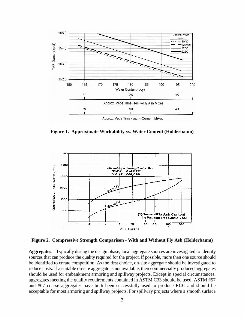
3
Figure 1. Approximate Workability vs. Water Content (Holderbaum)
Figure 2. Compressive Strength Comparison - With and Without Fly Ash (Holderbaum)
Aggregates: Typically during the design phase, local aggregate sources are investigated to identifysources that can produce the quality required for the project. If possible, more than one source shouldbe identified to create competition. As the first choice, on-site aggregate should be investigated toreduce costs. If a suitable on-site aggregate is not available, then commercially produced aggregatesshould be used for embankment armoring and spillway projects. Except in special circumstances,aggregates meeting the quality requirements contained in ASTM C33 should be used. ASTM #57and #67 coarse aggregates have both been successfully used to produce RCC and should beacceptable for most armoring and spillway projects. For spillway projects where a smooth surface
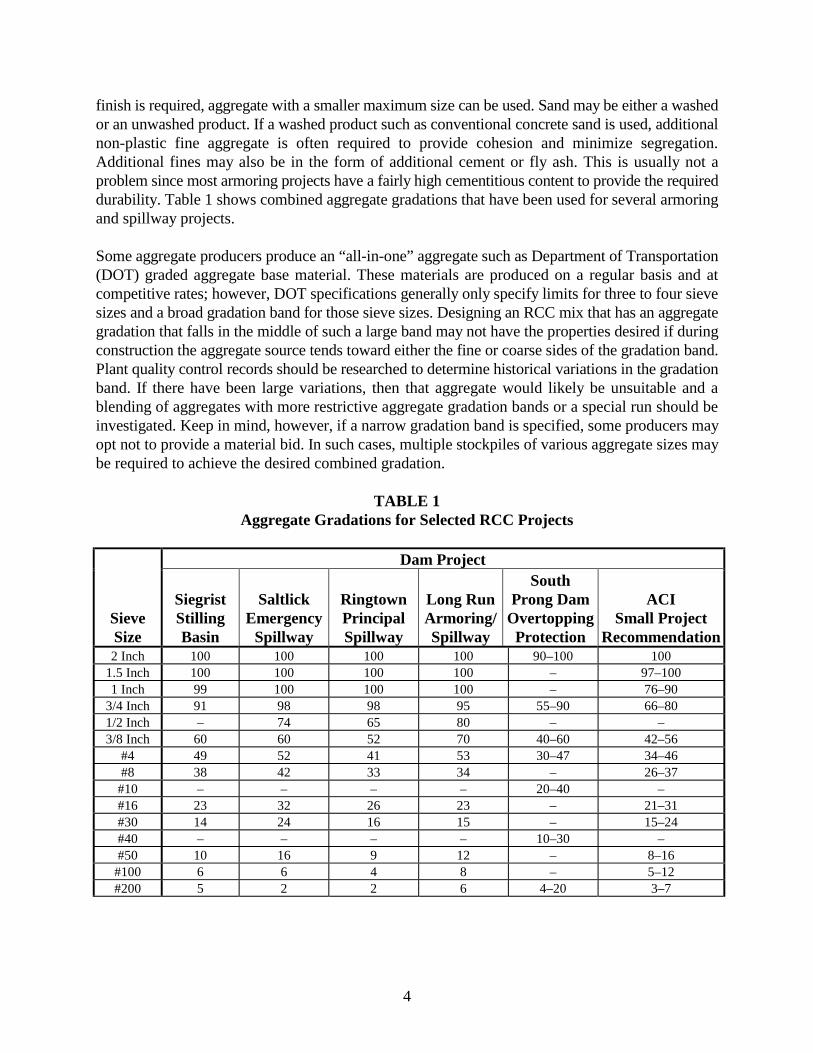
4
finish is required, aggregate with a smaller maximum size can be used. Sand may be either a washedor an unwashed product. If a washed product such as conventional concrete sand is used, additionalnon-plastic fine aggregate is often required to provide cohesion and minimize segregation.Additional fines may also be in the form of additional cement or fly ash. This is usually not aproblem since most armoring projects have a fairly high cementitious content to provide the requireddurability. Table 1 shows combined aggregate gradations that have been used for several armoringand spillway projects.
Some aggregate producers produce an “all-in-one” aggregate such as Department of Transportation(DOT) graded aggregate base material. These materials are produced on a regular basis and atcompetitive rates; however, DOT specifications generally only specify limits for three to four sievesizes and a broad gradation band for those sieve sizes. Designing an RCC mix that has an aggregategradation that falls in the middle of such a large band may not have the properties desired if duringconstruction the aggregate source tends toward either the fine or coarse sides of the gradation band.Plant quality control records should be researched to determine historical variations in the gradationband. If there have been large variations, then that aggregate would likely be unsuitable and ablending of aggregates with more restrictive aggregate gradation bands or a special run should beinvestigated. Keep in mind, however, if a narrow gradation band is specified, some producers mayopt not to provide a material bid. In such cases, multiple stockpiles of various aggregate sizes maybe required to achieve the desired combined gradation.
TABLE 1Aggregate Gradations for Selected RCC Projects
Dam Project
SieveSize
SiegristStillingBasin
SaltlickEmergency
Spillway
RingtownPrincipalSpillway
Long RunArmoring/Spillway
SouthProng Dam
OvertoppingProtection
ACISmall Project
Recommendation2 Inch 100 100 100 100 90–100 100
1.5 Inch 100 100 100 100 – 97–1001 Inch 99 100 100 100 – 76–90
3/4 Inch 91 98 98 95 55–90 66–801/2 Inch – 74 65 80 – –3/8 Inch 60 60 52 70 40–60 42–56
#4 49 52 41 53 30–47 34–46#8 38 42 33 34 – 26–37
#10 – – – – 20–40 –#16 23 32 26 23 – 21–31#30 14 24 16 15 – 15–24#40 – – – – 10–30 –#50 10 16 9 12 – 8–16
#100 6 6 4 8 – 5–12#200 5 2 2 6 4–20 3–7
5
Water: In general, water should meet the same requirements as for production of conventionalconcrete. If an on-site source of water is used it should be tested to determine its impact on strengthand set time of the concrete. At Big Haynes Dam in Georgia, on-site well water increased the initialset time by 15% over water from other sources. If an on-site source of water is available, it shouldbe tested and approved or rejected prior to bid.
Chemical Admixtures: Sufficient testing and evaluation have been completed to show thatadmixtures can be effective in RCC. Water-reducing, set-retarding, and air-entraining admixtureshave all been effectively used; however, they should be used only when absolutely necessary andafter full evaluation in the laboratory. High dosage rates are usually required for admixtures to beeffective. In addition, the RCC should have a measurable Vebe time. In ACI Committee Report207.5R it is reported that admixtures have been used successfully in RCC mixes with Vebe timesin the range of 10 to 30 seconds and that water-reducing and set-retarding admixtures wereeffectively used at Elk Creek Dam. The effectiveness of air entrainment can be tested with an airmeter identical to that used to test conventional concrete (ASTM C231). The effect of retardingadmixtures should be evaluated by set time testing of the mortar fraction of the RCC (ASTM C403).
MIX DESIGN(S)(Specification Paragraph 2.02)
Design Responsibility: Although it is probably best for the design engineer to design and proportionRCC mix(es) for the project, it is also acceptable for the designer to provide a performancespecification and require the contractor to design the RCC mix(es). In these cases, the designer needsto completely identify all required in-place concrete properties and define the battery of tests that arerequired to demonstrate that the contractor’s proposed mix(es) meet the specification requirements.All but the most sophisticated contractors will have to hire a consultant and/or testing laboratory toperform this work. At a minimum, if the contractor has the responsibility for mix design, he shouldbe given minimum requirements such as design strength, MSA, minimum cement content, etc.
Technical Approach: The technical approach selected for RCC mix design will depend on thedesigner’s preference and prior experience. There is currently a lack of agreement within the industryon design approach. As a result, several techniques for RCC mix design have evolved and any ofthese techniques can provide satisfactory results if they are correctly applied. A general descriptionof various design approaches can be found in ACI Committee Report 207.5R, “Roller-CompactedMass Concrete.” Specific details of each approach, however, are not provided in this document.
Design Guidelines and References: Numerous reference documents that provide information onRCC mix design are available to the design engineer. Several documents that provide specific RCCmix design procedures are listed below:
(1) U.S. Army Corps of Engineers, EM 1110-2-2006, Roller-Compacted Concrete,February, 1992.
6
(2) U.S. Department of the Interior, Bureau of Reclamation, ACER Technical MemorandumNo. 8, “Guidelines for Designing and Constructing Roller-Compacted Concrete Dams,”June 1987.
(3) Tatro, S. B., and J. K. Hinds, “Roller-Compacted Concrete Mix Design,” SymposiumVolume of the American Society of Civil Engineers, February 1992.
(4) Dolen, T. P., “Mixture Proportioning – The Concrete Approach,” Proceedings of theInternational RCC Dams Seminar & Study Tour, September 1998.
(5) Choi, K., “RCC Mix Design – Soils Approach,” Proceedings of the International RCCDams Seminar & Study Tour, September 1998.
(6) Schrader, E. K., “Roller-Compacted Concrete for Dams – State-of-the-Art,” InvitedPaper for International Conference on Advances in Concrete Technology, Athens,Greece, May 1992.
(7) McDonald, J. E., and N. F. Curtis, “Applications of Roller-Compacted Concrete inRehabilitation and Replacement of Hydraulic Structures,” U.S. Army Corps ofEngineers, Technical Report REMR-CS-53, April 1997.
(8) Holderbaum, R. E., and R. A. Kline, “Roller-Compacted Concrete Mix Design andTesting,” Association of State Dam Safety Officials Annual Conference, Pittsburgh, PA,1997.
(9) American Concrete Institute, Committee 207, ACI 2.07.5, Roller-Compacted MassConcrete
(10) McLean, F.G. and Hansen, K.D., “Roller-Compacted Concrete for EmbankmentOvertopping Protection,” Geotechnical Practice, Dam Rehabilitation, Raleigh, NC,ASCE, New York, April 1993
Criteria: The criteria for design of RCC mixes should be:
(1) Provide adequate strength to meet structural design loads with normal factors of safety.(2) Minimize internal heat rise from hydration and subsequently developed stress or crack
potential.(3) Provide a constructable mix.(4) Provide a durable wearing surface.(5) Provide economy.
Testing and Procedures: Laboratory tests are necessary to develop mix properties for the designof the structure and set density targets for use in the field. Although roller-compacted concrete hasbeen in use for over 20 years, very few standards currently exist that have been specificallydeveloped for testing RCC. Test methods, procedures, and equipment to some extent are dependent
7
on the method selected for the RCC mix design and the desired properties of the RCC mix. Generaltest procedures are described in the references included in the paragraph titled “Design Guidelinesand References.” ASTM standards that are currently adopted specifically for RCC include:
ASTM C1170 – Determining Consistency and Density of Roller-Compacted Concrete Using aVibrating Table
ASTM C1176 – Making Roller-Compacted Concrete in Cylinder Molds Using a Vibrating Table
ASTM C1435 –Standard Practice for Molding Roller-Compacted Concrete in Cylinder Molds Usinga Vibrating Hammer
In addition, ASTM standards developed for conventional concrete are often applicable for RCC orcan be adapted to RCC with suitable modifications. An experienced engineer or lab technicianshould be consulted if there is any question regarding the applicability of a particular test orprocedure.
Molding RCC Cylinders: There are two primary approaches for preparing RCC cylinders in thefield for the drier mixes (Vebe times greater than about 30 seconds) often used in RCC overtoppingprotection and emergency spillways. They are the vibrating hammer and the pneumatic pole tamper.The vibrating hammer method has been in use for a number of years and is approved as an ASTMtest procedure (ASTM C1435). This method works well on moderately dry mixes but may notproduce enough compactive effort for the very dry mixes. For the drier mixes the pneumatic poletamper has been used successfully to compact RCC in cylinder molds. Special cylinder collars arerequired to keep the tamping head from striking the edges of the mold due to the large amplitude ofthe tamping head.
For wetter mixes with Vebe times of less than about 30 seconds, either the vibrating hammer orVebe apparatus (ASTM C1176) can be successfully used to mold cylinders. RCC may not be fullyconsolidated by the Vebe apparatus for Vebe times greater than about 30 seconds.
Soil compaction rammers have also been used to mold RCC cylinders. A concern with this methodis the potential for aggregate breakdown during compaction, particularly with drier mixes. In onestudy conducted, a test in which the gradation of the RCC aggregate was determined before and aftercompaction by this method found that significant aggregate fracturing can occur, especially withlower quality aggregate. If aggregate fracturing is significant, the compressive strength determinedin the laboratory may not be representative of what can be achieved during construction.
Mix Adjustment During Construction: Mix adjustments during construction are often necessaryand can be easily accommodated. The need for cement and/or pozzolan adjustments in most caseswill be determined from test results that show both the anticipated in-place properties and variabilityof the RCC. Adjustment to aggregate gradations or proportions can be necessitated by observingsegregation during handling or by a requirement for a better surface finish on spillway slabs.Addition of admixtures may be desired as a result of a delay of placement in warmer climaticconditions. For example, a set retarder could be used to extend the working time during warm

8
weather placing conditions. In all cases, except for water content adjustments, mix adjustmentsshould be made by the design engineer, and only when sufficient test data are available to supportthe change. Water content adjustments can be assigned to the contractor, provided that an upper limitis provided by the specifications.
EQUIPMENT SELECTION(Specification Paragraph 2.03)
Plant Type
General Background: Many kinds of mixing plants have been used successfully for production ofRCC. Continuous-mix and batch-type mixers have both been employed for a wide range of RCCmixes. For small volume projects, volumetric proportioning pugmill mixers have been used the mostbecause of their availability and simple setup. Although batch-type drum mixers are capable ofmixing RCC, bulking in the mixer reportedly reduces mixer capacity as much as 15%. Continuous-mix plants can have difficulty in monitoring cement and pozzolan contents, although when properlycalibrated have been found to provide adequate accuracy. Continuous-mix plants typically havegreater production capacity compared to a comparable batch-type drum mixer; however, they alsohave greater power requirements. Although weight controls are not normally necessary with the typeof mixes to be used, the contractor may submit for approval a mixing plant that uses weight controls.
Specification Considerations: Pugmill mixing plants are generally accepted as being more efficientfor mixing RCC and should be given first consideration if the designer is specifying the plant type.Drum mixers may be permitted by the specifications, but precautions concerning their use andpotential additional costs associated with bulking and segregation should be addressed in thespecifications. Transit truck mixers have been found to cause significant segregation for mixes withaggregate larger than one inch. For very low volume projects, transit truck mixers may be the mosteconomical choice. Care must be taken to avoid segregation and wide swings in moisture. Toadequately discharge the RCC, the front of the truck must be higher than the back of the truck.
Mixing Plant Capacity: Mixing plant capacity is a function of the required RCC placementquantity; hourly, daily, or seasonal time limitations; lift variability; and other concurrent activities.It is not uncommon for mixing plant capacity to be 30% higher than the designed sustainableproduction capacity and 100% higher than the project average placement rate. For large volumeprojects with extremely critical schedules, the designer may want to specify the minimum numberand capacity of concrete plants. Otherwise, selection can be left to the contractor. For small volumeprojects, a plant capacity of 100 cubic yards per hour is usually sufficient to meet the contractor’splanned placement rate.
Mixing Plant Operation: Continuous mix pugmills are designed to operate most efficiently on acontinuous basis with few stops and starts. For most overtopping protection and spillway projects,the placement production rates will be low, with only a few hauling vehicles required to maintainan adequate supply of RCC from the mixing plant to the lift surface. This typically results in thecontinuous plants stopping and starting on a frequent basis. One way to minimize the number ofinterruptions is to have a large capacity gob hopper that serves as a temporary storage device so the
9
plant can continue to operate even though a hauling vehicle is not available. Requiring a large gobhopper may be an unnecessary expense for smaller volume projects.
The issue in question is what is the quality of the RCC during the first seconds of plant operationafter the plant has been stopped. If the pugmill has previously discharged the entire contents of themixing chamber, the RCC produced when the plant restarts, except for a nominal amount, will beproperly proportioned and uniformly mixed. Many RCC specifications require that the first 1-2 cubicyards of material produced after a plant shutdown be wasted. In most instances this is unnecessarywaste. The specifications should allow for the engineer to reject any RCC not mixed in the properproportions or consistency, but stipulating an arbitrary amount of material to be wasted is overlyrestrictive. The engineer should monitor the plant operations during startup and then decide if anymaterial should be wasted. It may be prudent that at the start of each day, or if the mixing plant hasbeen inoperable for over 30 minutes, that the first 10–20 seconds of material produced be wasted.Prolonged plant shutdowns can sometimes cause initial material feed problems. During the testsection construction, the engineer should observe the operations of the plant and the consistency ofthe mix during all phases of the plant’s operation.
Mixing Time: Many of the earlier RCC specifications were written requiring continuous pugmillsto have minimum mixing times of 20–30 seconds and have the ability to increase the mixing time.The majority of the continuous pugmills in the United States do not have the ability to modify theamount of time the material is in the mixing chamber. Specifications have suggested inclining themixing chamber or reversing the paddles as ways of increasing mixing time. These options havebeen found to have negligible effect. Historically, the performance of the continuous pugmills inproducing a uniform RCC mix has been excellent and these types of pugmills have been used on themajority of the over 150 RCC projects completed.
If the contractor proposes to use a pugmill that has mixed RCC of similar proportions and has anoperator experienced with the plant and RCC, his plant should be acceptable. As always, theselection of the equipment for RCC mixing is the contractor’s responsibility, and if duringproduction his plant proves unacceptable in producing a uniform RCC mix, he must either makecorrections to his plant or replace it with a different one.
Delivery Equipment: RCC has been delivered with end-dump trucks, bottom-dump off-roadhaulers, front-end loaders, and conveyors. For most projects, except where access is difficult,conveyor delivery is probably not practical. Although not the best choice from a quality standpoint,armoring projects are well suited for truck delivery due to their size and general layout. If the RCCmix is well proportioned, has a small maximum size aggregate, a high sand content, and a moderateto high water content, dumping from an end-dump truck can usually be tolerated. If trucks are usedto deliver RCC, restrictions should be incorporated in the specifications to minimize segregationsuch as not allowing discharging RCC directly against any formwork.
Spreading Equipment: Spreading equipment should be limited to a D-4 or comparable size dozerfor small projects and a D-6 for large projects. ABG pavers have also been used. A front-end loaderis often required for placing material in confined areas.
10
SCHEDULE CONSIDERATIONS(Specification Paragraph 3.01)
Thermal Stress Considerations: In general, a thermal stress analysis is probably not required formost armoring and spillway projects if cracking can be tolerated. The need to perform a thermalstress analysis will depend on the size and complexity of the project. Several general guidelinesshould be considered, however, if specifying the placement time and schedule:
(1) Thermal stresses and cracking can be minimized by placing during cool weather inthe spring of the year. Placement during the fall season may subject “young” RCCto thermal shock if proper insulating precautions are not taken.
(2) If possible, RCC should be placed when the daily average temperature is below themean annual temperature of the site.
(3) Advance stockpiling of aggregates during cold weather will probably not bebeneficial unless the project and the stockpiles are large.
(4) Night placement during hot weather in combination with daytime shutdown and aneffective curing system can significantly reduce peak RCC temperatures.
(5) A highly effective moist cure during warm weather is essential.
Special Restrictions: Meeting the specified placement dates is necessary to obtain the desired in-place properties of the RCC and to minimize the potential for cracking. If the contractor fails to meetthe required schedule, the engineer should perform a re-analysis of the placement schedule andadvise the contractor of any special requirements or restrictions that must be taken to obtain similarin-place material properties. The analysis will require a minimum of 7 days to complete. During thattime, the contractor should not be permitted to place RCC without prior approval from the engineer.Special restrictions or requirements that might be necessitated include, but are not limited to, reducedor accelerated placement rates, installation of surface insulation following placement each day or atcompletion of all RCC, pre- or post-cooling of materials, and placing during specified hours eachday.
Lift Joint Quality: While often an important issue for most RCC dams, the concern for lift jointquality is greatly reduced for most embankment armoring projects. That is not to say that jointquality can be totally ignored. However, very little cohesion is probably needed to satisfy mostdesigns. Therefore, schedule requirements do not necessarily need to be driven by lift joint qualityrequirements, and specifications should be prepared accordingly. For spillways with high velocities,however, the design may require development of tensile strength across lift joints to preventdelamination of lift layers during high flows. In these cases, lift joint quality requirements maynecessitate placement quickly and during cool weather to achieve the required bond strength. If thiscannot be accommodated, bedding mix may be needed for joint treatment.
A Lift Joint Quality Index score card has been developed which assigns both positive and negativepoints to factors such as surface segregation, lift maturity, type of delivery systems used, curing,etc.(1) On small projects, such a score card is cumbersome to use in the field; however, these factorsprovide guidelines that should be in the minds of everyone working on the lift surface. Because many
(1) Schrader, E.K., “Shear Strength and Lift Joint Quality of RCC,” Hydropower & Dams, Vol.VI, Issue One, 1999.
11
of the factors used to evaluate the condition of a lift surface are somewhat subjective, it is importantto develop a clear understanding of lift joint treatment requirements with the prospective contractorsduring the bid period. Small isolated areas of contamination, such as an oil leak or dirt from a dozertrack, do not generally require special attention but should serve as a reminder to the contractor toremedy the situation before it affects production.
Cost Considerations: The lowest project cost will be achieved when the least schedule restrictionsare placed on the contractor. Unless the owner requires completion by a certain time, or technicalreasons require placement during a particular time of the year or at a particular rate, the workschedule should be left to the contractor.
FOUNDATION PREPARATION(Specification Paragraph 3.02)
Placement on Rock Foundations: If placement on a rock foundation is required by the design,cleanup and preparation of the rock surface should be comparable to that performed for conventionalconcrete placement on rock surfaces. All loose rock, soil, debris, mud, ice, and snow must beremoved, and the rock surface must be absolutely free of any flowing water prior to placing RCC.If a high degree of shearing resistance is to be provided by the foundation, bedding mix should beplaced on the rock surface immediately prior to placing RCC.
Placement on Earth Foundations: The compactability of the first two or three lifts of RCC on anearth foundation depends in part on the density of the earth subgrade. It is essential that all loose orwet material be removed and replaced with suitable earth backfill. The entire subgrade should bemoisture conditioned and compacted with compactive effort equal to or greater than that used forthe RCC. The designer should include a separate specification in the bid documents that describesrequirements for subgrade treatment, fill placement, and compaction.
Foundation Dewatering: Achieving a suitably dewatered foundation is a common problem forplacement areas located below local groundwater. Most RCC mixes are adversely impacted byadditional water; therefore, dewatering the placement area to dry or slightly damp conditions isessential. Any of the common methods for dewatering deep foundations can be used for RCCembankment armoring and spillway projects. However, the specifications should clearly statewhether dewatering facilities will be permitted within the placement area and, if so, the maximumnumber and minimum spacing of dewatering points. Closely spaced obstacles within the placementarea will seriously affect the placement speed and quality of the RCC. Earth materials that aresaturated are a common problem encountered in embankment armoring projects. The subsurfaceexploration program should identify such potential problem areas. Project specifications and biddocuments should advise the contractor of potential problems and allow time in the schedule fordrying of materials.
Use and Design of Bedding Mix: Bedding mix is often used between rock foundations and the firstRCC lift and between RCC layers to increase the lift joint shear strength and decrease jointpermeability. For most embankment armoring and spillway projects, the need for bedding mix isminimal. If required by the design, bedding mix that can be easily handled and placed should be

12
specified. Two types of bedding mix have been used. The first type of bedding mix, often referredto as bedding mortar, contains only fine aggregate and can be spread to a thickness of ½ inch to 1inch. It is easier to handle and spread than bedding mix containing coarse aggregate. The second typeusually contains aggregate with a maximum size of ¾ inch or 1 inch and is placed at a thickness ofone to one-and-a-half times the maximum aggregate size. This type of bedding requires additionalcost to produce and is more difficult to transport and place. If the slump is too high, the coarseaggregate will segregate from the mix if not handled properly. Except in cold weather, bedding mixshould contain a water reducing/retarding admixture to prevent rapid set and loss of workability.
For overtopping protection and spillway projects, bedding mortar is typically specified for the top2 to 3 lifts in the stilling basin or run-out apron, and at the crest of the structure. These locations havevery little confining weight in which to mobilize the shear friction, so cohesion between liftsbecomes important.
PLANT CALIBRATION AND TESTING(Specification Paragraph 3.03)
Procedures for concrete plant calibration vary depending on the type and manufacturer of the plant.This Commentary is not intended to provide a definitive guide to plant calibration; however, severalpertinent observations are offered for consideration.
Although plant types vary considerably, one of the most common plants for mixing RCC is thecontinuous mix pugmill plant. For this type of plant, the final test of calibration should include directmeasurement of weights of each individual material metered through the plant over a set time period.With this information, the actual feed rates can be computed and then compared with the theoreticalplant setting to determine if material feed rates are within specified tolerances. Plant manufacturersshould be consulted if there is any question regarding acceptable calibration procedures.
During construction, the plant should be re-calibrated any time a plant setting that controls cement,pozzolan, or aggregate feeds is modified. Even minor changes to plant settings have been discoveredto result in significant changes to material feed rates resulting in RCC that does not meetspecifications.
13
AGGREGATE PRODUCTION, DELIVERY AND HANDLING(Specification Paragraph 3.04)
Aggregate Stockpiling: When a narrow gradation band is specified, there are several locationswhere the material may fall out of specification after it leaves the producer. Proper construction ofthe on-site stockpile is essential to prevent segregation. Both the engineer and the contractor mustmonitor the delivery of the aggregate and instruct equipment operators on proper stockpilingprocedures to minimize segregation. Before RCC production, the loader operator feeding the mixingplant must be instructed on proper loading methods from the face of the stockpile to prevent deliveryof “out of specification” aggregates to the mixing plant. Pre-placement training of the equipmentoperators can help alleviate most of the problems associated with aggregate segregation.
One acceptable method of stockpiling is delivery by truck onto the top of the stockpile, dumping theloads in adjacent piles, spreading the piles with a bulldozer, and repeating the process in spreadlayers to raise the pile. Care must be used to avoid substantial spilling of material over the edge ofthe piles, causing a segregated outside shell of unsuitable material. Care must also be taken not toexcessively track portions of the stockpile with the bulldozer. Excessively tracking the stockpile canbreak down the aggregate and significantly alter the gradation of the stockpiled aggregate.
In general, temperature monitoring of stockpile temperatures is not necessary for embankmentarmoring and spillway projects. For projects that do require monitoring, specifications for thethermocouples and installation should be provided in this section or in a separate instrumentationsection. The number of thermocouples required, the frequency of reading, and the frequency forsubmission of readings to the engineer should be specified as appropriate. If temperature is asignificant concern, the design engineer should consider inclusion of a detailed delivery schedule.
TRIAL PLACEMENT(Specification Paragraph 3.05)
The test section is intended as a practice, training, and orientation area; to help evaluate the practicaleffectiveness of various construction methods and pieces of equipment; to practice quality controlrequirements; to make final mix adjustments; and to determine the optimum compaction densityvalue. The trial placement will also serve as a practice area for inspection.
General: A trial placement that is outside of the permanent work or incorporated into a non-criticalstructure is usually required to visually verify mix properties, confirm achievable in-place density,and provide a practice area for the contractor.
Specification Details: The specifications should describe the requirements and anticipated outcomesof the trial placement in as much detail as possible. It should be clearly stated that if the goals arenot achieved, the scope of the trial placement will be increased. The measurement and paymentsection of the bid documents should address payment for the Trial Placement, including increasedscope caused by either the contractor or engineer.
14
CONVEYING AND TRANSPORTING(Specification Paragraph 3.07)
System Coordination: Delivery equipment must be compatible with the plant capacity and thecapacity of spreading and compaction equipment on the lift surface. The specification need notprovide detail on this issue, but it should require contractor submittals to include rates for allactivities.
Haul Vehicles: As previously stated, RCC has been hauled in end-dump trucks, off-road bottom-dump haulers, and front-end loaders. All three types of vehicles have been used successfully withproper precautions and placing procedures. Although end-dump trucks are probably the mostcommon haul vehicles used for small projects, their use will result in some segregation with mostRCC mixes. However, many of these projects can tolerate a small amount of segregation. Further,additional measures can be employed on the lift surface to remove and/or reblend segregatedmaterial.
Conveyor Systems: Belt conveyors typically are not required to successfully construct embankmentarmoring or spillway projects. If the project is located in a very wet environment or if a high degreeof lift quality is required for technical reasons, the design engineer may specify a conveyor deliverysystem. Otherwise, the choice of delivery should be left to the contractor. In some cases a partialconveyor system might be appropriate; for example, conveyor delivery from the mixing plant to atransfer point on the lift surface.
If conveyors are used, careful attention should be given to matching the capacity of plant andspreading equipment on the lift surface. This information should be requested as part of the submittalprocess.
Portable conveyors that are used for transport of conventional concrete, aggregate, and coal have allbeen used successfully for transport of RCC. Conveyor transfer points, however, can often be asource of problems and can result in significant down time.
PLACING AND SPREADING(Specification Paragraph 3.08)
Selection of Temperature Restrictions: The specifications should set a lower and upper limit onthe allowable temperature of fresh RCC delivered to the lift surface. The lower limit is to preventfrozen RCC from being placed, while the upper limit is to minimize the potential for developmentof high thermal stresses. Thermal stresses may produce strains that exceed the capacity of the RCC,resulting in uncontrolled cracking. For overtopping protection and spillways with infrequent flows,cracking is generally not a problem, but if the structure will experience frequent flows, minimizinguncontrolled cracking is a consideration.
15
Most RCC embankment overtopping protection and emergency spillway projects do not includetransverse contraction joints. The maximum allowable RCC temperature is a function of the averageambient temperature in the geographical area of the project, daily and seasonal temperaturefluctuations, and the expected rise in temperature of the RCC mix as the cement hydrates. Thedifference between the temperature of the RCC mass and the outside ambient temperature can createthermal stresses. To minimize the potential for a large differential between the two temperatures, anRCC placement schedule “window” is often defined in the specifications. Some designers will allowthe RCC to be 15 °F greater than the annual average temperature at the site if RCC placement isduring the day and possibly more if RCC is placed at night. Several projects have used a dailyweighted-average maximum temperature that provides some relief to the contractor. While recordkeeping can be tedious, this concept allows the contractor to increase total placement hours, becauseplacing during the cooler night-time temperatures usually offsets higher RCC temperatures that resultduring warmer daytime conditions.
During the development of the preliminary design of the project, the RCC mix design, thermalanalysis (if performed), and project schedule will all play a part in determining the temperaturerestrictions and time of year when the RCC must be placed. The project schedule must allow enoughtime for all of the required front-end work to be completed in preparation for the RCC placement,with some contingency time built into the schedule to accommodate items such as inclement weatherand unforeseen subsurface conditions. Without flexibility in the mix design or schedule, missing anyspecified placement windows may result in the owner and/or the contractor incurring expensesassociated with cooling the various mix components and/or the RCC mix. Adequate planning duringthe design process and developing contingency plans for alternative RCC placement schedules willhelp prevent excessive delays and additional costs during construction.
Placing During Precipitation: Experience has shown that placing RCC during a temporary lightmist can usually be accomplished with care, but if hauling vehicles rather than conveyors are usedfor delivery, it is relatively easy to contaminate or damage the surface and subsequently have to cleanit. If rain alters the mixture proportions beyond acceptable limits, the RCC will need to be removed.The contractor should have provisions to cover the lift during periods of heavy rains.
Selection of Lift Thickness: For most projects a lift thickness of 12 inches should be specified bythe design engineer. Although thicker lifts have been used in some instances, complications arisingfrom use of thicker lifts are not usually justified for most armoring and spillway projects. Thickerlifts require additional compaction trials and testing to confirm that the desired in-place density canbe achieved. Placement of thicker lifts may also complicate grade control and nuclear density testing.By contrast, 12-inch lifts have been used for many projects and can be adequately compacted withcommon compaction equipment. The specifications can require RCC to be placed in 6-inch liftsagainst formwork to achieve better compaction for the full depth of the lift or in other areas wherea large vibratory roller cannot operate properly.
16
Equipment Selection: Ultimately, the contractor has the responsibility for selecting equipment thatis suitable for placing and spreading RCC. However, the engineer is often required to reviewcontractor equipment submittals. As a general guide for spreading equipment, a D-3 can be expectedto spread a 12-inch lift at a maximum rate of about 100 cubic yards per hour. A D-5 has a spreadingcapacity of nearly 200 cubic yards per hour. The capacity of the spreading equipment, however, ishighly dependent on the method of RCC placement, the care taken in grade control, and operatorability.
COMPACTION(Specification Paragraph 3.09)
Determination of Required Density: The density of the RCC has a direct role in the strength of theRCC. Two factors that can produce changes in the density during construction, assuming compactioneffort is unchanged, are the moisture content and changes in the aggregate gradation, includingsegregation. Moisture content can be easily adjusted at the mix plant, but segregation and/or changesin the gradation of the aggregate may be more difficult to manage because of the number of differenthandlers of the material.
Numerous projects were studied by observing the maximum density achieved versus the compressivestrengths of RCC samples (Figure 3). The data indicates that for compacted densities between 97%and 100% of theoretical air-free density, the compressive strength of the RCC showed little variation.However, as the air-free density drops below 96%, strength loss occurs. The Bureau of Reclamationrequires 99% of the average maximum density (AMD) achieved during lab compaction trials. Theyconsider this requirement, along with a highly workable mix, essential to achieve full compactionof the RCC lift. There are some concerns that settling for a minimum density of 97% will not ensureadequate density at the bottom of the lift. The concern of the Bureau may be justified if a largeaggregate is used in combination with a mix with a low degree of workability. (Note: The readershould be aware that 99% of the AMD is not equivalent to 99% of air-free density because there aresome voids—usually 0% to 2 %—in the AMD.)
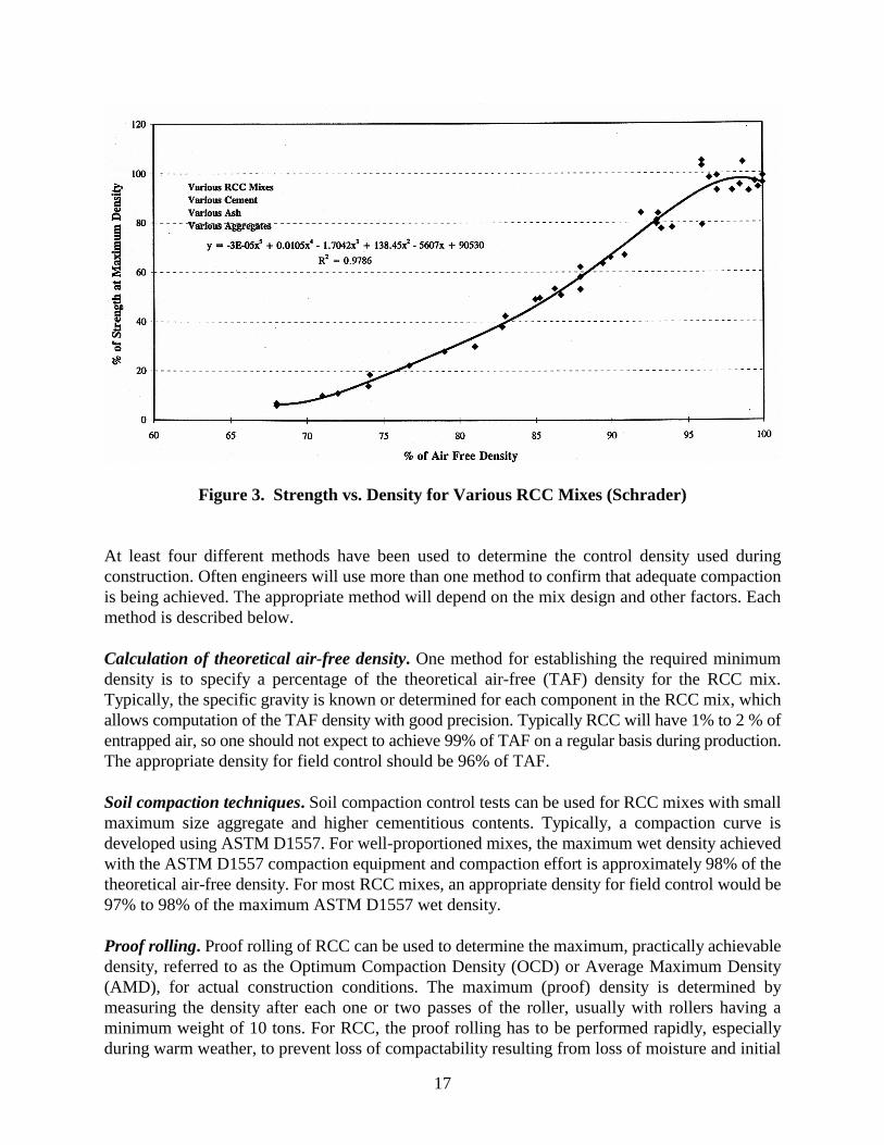
17
Figure 3. Strength vs. Density for Various RCC Mixes (Schrader)
At least four different methods have been used to determine the control density used duringconstruction. Often engineers will use more than one method to confirm that adequate compactionis being achieved. The appropriate method will depend on the mix design and other factors. Eachmethod is described below.
Calculation of theoretical air-free density. One method for establishing the required minimumdensity is to specify a percentage of the theoretical air-free (TAF) density for the RCC mix.Typically, the specific gravity is known or determined for each component in the RCC mix, whichallows computation of the TAF density with good precision. Typically RCC will have 1% to 2 % ofentrapped air, so one should not expect to achieve 99% of TAF on a regular basis during production.The appropriate density for field control should be 96% of TAF.
Soil compaction techniques. Soil compaction control tests can be used for RCC mixes with smallmaximum size aggregate and higher cementitious contents. Typically, a compaction curve isdeveloped using ASTM D1557. For well-proportioned mixes, the maximum wet density achievedwith the ASTM D1557 compaction equipment and compaction effort is approximately 98% of thetheoretical air-free density. For most RCC mixes, an appropriate density for field control would be97% to 98% of the maximum ASTM D1557 wet density.
Proof rolling. Proof rolling of RCC can be used to determine the maximum, practically achievabledensity, referred to as the Optimum Compaction Density (OCD) or Average Maximum Density(AMD), for actual construction conditions. The maximum (proof) density is determined bymeasuring the density after each one or two passes of the roller, usually with rollers having aminimum weight of 10 tons. For RCC, the proof rolling has to be performed rapidly, especiallyduring warm weather, to prevent loss of compactability resulting from loss of moisture and initial
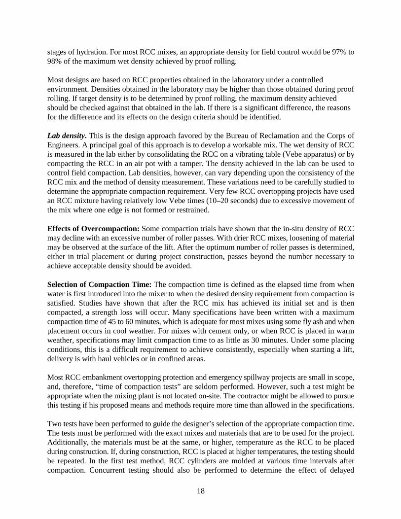
18
stages of hydration. For most RCC mixes, an appropriate density for field control would be 97% to98% of the maximum wet density achieved by proof rolling.
Most designs are based on RCC properties obtained in the laboratory under a controlledenvironment. Densities obtained in the laboratory may be higher than those obtained during proofrolling. If target density is to be determined by proof rolling, the maximum density achievedshould be checked against that obtained in the lab. If there is a significant difference, the reasonsfor the difference and its effects on the design criteria should be identified.
Lab density. This is the design approach favored by the Bureau of Reclamation and the Corps ofEngineers. A principal goal of this approach is to develop a workable mix. The wet density of RCCis measured in the lab either by consolidating the RCC on a vibrating table (Vebe apparatus) or bycompacting the RCC in an air pot with a tamper. The density achieved in the lab can be used tocontrol field compaction. Lab densities, however, can vary depending upon the consistency of theRCC mix and the method of density measurement. These variations need to be carefully studied todetermine the appropriate compaction requirement. Very few RCC overtopping projects have usedan RCC mixture having relatively low Vebe times (10–20 seconds) due to excessive movement ofthe mix where one edge is not formed or restrained.
Effects of Overcompaction: Some compaction trials have shown that the in-situ density of RCCmay decline with an excessive number of roller passes. With drier RCC mixes, loosening of materialmay be observed at the surface of the lift. After the optimum number of roller passes is determined,either in trial placement or during project construction, passes beyond the number necessary toachieve acceptable density should be avoided.
Selection of Compaction Time: The compaction time is defined as the elapsed time from whenwater is first introduced into the mixer to when the desired density requirement from compaction issatisfied. Studies have shown that after the RCC mix has achieved its initial set and is thencompacted, a strength loss will occur. Many specifications have been written with a maximumcompaction time of 45 to 60 minutes, which is adequate for most mixes using some fly ash and whenplacement occurs in cool weather. For mixes with cement only, or when RCC is placed in warmweather, specifications may limit compaction time to as little as 30 minutes. Under some placingconditions, this is a difficult requirement to achieve consistently, especially when starting a lift,delivery is with haul vehicles or in confined areas.
Most RCC embankment overtopping protection and emergency spillway projects are small in scope,and, therefore, “time of compaction tests” are seldom performed. However, such a test might beappropriate when the mixing plant is not located on-site. The contractor might be allowed to pursuethis testing if his proposed means and methods require more time than allowed in the specifications.
Two tests have been performed to guide the designer’s selection of the appropriate compaction time.The tests must be performed with the exact mixes and materials that are to be used for the project.Additionally, the materials must be at the same, or higher, temperature as the RCC to be placedduring construction. If, during construction, RCC is placed at higher temperatures, the testing shouldbe repeated. In the first test method, RCC cylinders are molded at various time intervals aftercompaction. Concurrent testing should also be performed to determine the effect of delayed
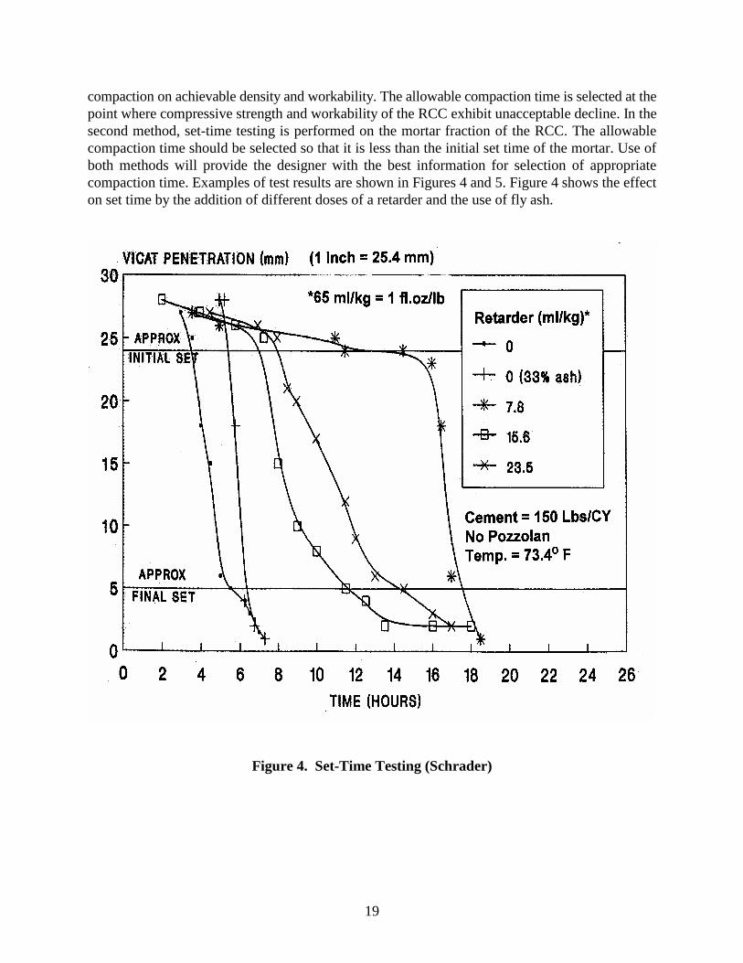
19
compaction on achievable density and workability. The allowable compaction time is selected at thepoint where compressive strength and workability of the RCC exhibit unacceptable decline. In thesecond method, set-time testing is performed on the mortar fraction of the RCC. The allowablecompaction time should be selected so that it is less than the initial set time of the mortar. Use ofboth methods will provide the designer with the best information for selection of appropriatecompaction time. Examples of test results are shown in Figures 4 and 5. Figure 4 shows the effecton set time by the addition of different doses of a retarder and the use of fly ash.
Figure 4. Set-Time Testing (Schrader)
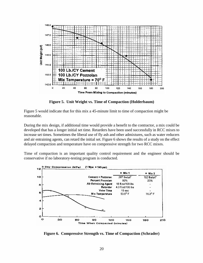
20
Figure 5. Unit Weight vs. Time of Compaction (Holderbaum)
Figure 5 would indicate that for this mix a 45-minute limit to time of compaction might bereasonable.
During the mix design, if additional time would provide a benefit to the contractor, a mix could bedeveloped that has a longer initial set time. Retarders have been used successfully in RCC mixes toincrease set times. Sometimes the liberal use of fly ash and other admixtures, such as water reducersand air entraining agents, can retard the initial set. Figure 6 shows the results of a study on the effectdelayed compaction and temperature have on compressive strength for two RCC mixes.
Time of compaction is an important quality control requirement and the engineer should beconservative if no laboratory-testing program is conducted.
Figure 6. Compressive Strength vs. Time of Compaction (Schrader)
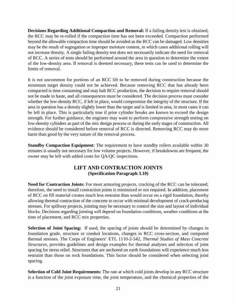
21
Decisions Regarding Additional Compaction and Removal: If a failing density test is obtained,the RCC may be re-rolled if the compaction time has not been exceeded. Compaction performedbeyond the allowable compaction time should be avoided as the RCC can be damaged. Low densitiesmay be the result of segregation or improper moisture content, in which cases additional rolling willnot increase density. A single failing density test does not necessarily indicate the need for removalof RCC. A series of tests should be performed around the area in question to determine the extentof the low-density area. If removal is deemed necessary, these tests can be used to determine thelimits of removal.
It is not uncommon for portions of an RCC lift to be removed during construction because theminimum target density could not be achieved. Because removing RCC that has already beencompacted is time consuming and may halt RCC production, the decision to require removal shouldnot be made in haste, and all consequences must be considered. The decision process must considerwhether the low-density RCC, if left in place, would compromise the integrity of the structure. If thearea in question has a density slightly lower than the target and is limited in area, in most cases it canbe left in place. This is particularly true if prior cylinder breaks are known to exceed the designstrength. For further guidance, the engineer may want to perform compressive strength testing onlow-density cylinders as part of the mix design process or during the early stages of construction. Allevidence should be considered before removal of RCC is directed. Removing RCC may do moreharm than good by the very nature of the removal process.
Standby Compaction Equipment: The requirement to have standby rollers available within 30minutes is usually not necessary for low volume projects. However, if breakdowns are frequent, theowner may be left with added costs for QA/QC inspections.
LIFT AND CONTRACTION JOINTS(Specification Paragraph 3.10)
Need for Contraction Joints: For most armoring projects, cracking of the RCC can be tolerated;therefore, the need to install contraction joints is minimized or not required. In addition, placementof RCC on fill material creates much less restraint than would occur on a rigid foundation, therebyallowing thermal contraction of the concrete to occur with minimal development of crack-producingstresses. For spillway projects, jointing may be necessary to control the size and layout of individualblocks. Decisions regarding jointing will depend on foundation conditions, weather conditions at thetime of placement, and RCC mix properties.
Selection of Joint Spacing: If used, the spacing of joints should be determined by changes infoundation grade, structure or conduit locations, changes in RCC cross-section, and computedthermal stresses. The Corps of Engineers’ ETL 1110-2-542, Thermal Studies of Mass ConcreteStructures, provides guidelines and design examples for thermal analyses and selection of jointspacing for stress relief. Structures that are anchored on earth foundations will experience much lessrestraint than those on rock foundations. This factor should be considered when selecting jointspacing.
Selection of Cold Joint Requirements: The rate at which cold joints develop in any RCC structureis a function of the joint exposure time, the joint temperature, and the chemical properties of the
22
cement and fly ash. The first two factors can be combined in a term called “lift joint maturity,”usually expressed in degree-hours. A cold joint is determined to exist when a specified degree-hourlimit is exceeded. Cold joint limits in specifications have typically ranged from 500 to 2000 degree-hours (F). Selection of the appropriate value should be based on the joint properties required tosatisfy the design. In general, shear strength can be expected to decrease with increased lift jointmaturity and permeability can be expected to increase. The lift joint maturity degree-hours have littleeffect on the friction component of the shear properties at the lift joint, but as the degree-hoursincrease, the cohesion between the two lift surfaces decreases. If substantial cohesion is requiredbetween the two lifts to satisfy design criteria then one should tend towards the 500 degree-hourslimit. If little cohesion is required, then the upper limit might be acceptable. Although theseproperties are not as critical as they are for design of a gravity dam, they should be considered whenpreparing the specifications. Published values of shear strength and permeability for selected mixescan be found in ACI Committee Report 207.5R.
On small projects or where occurrence of colds joints is not a significant problem, basing cold jointcriteria on a set number of hours, as opposed to degree-hours, may be acceptable. This practice hasbeen implemented on some projects and has simplified the process for both contractor personnel andthe inspection staff. This procedure allows the contractor to better plan and schedule his labor andmaterials because he knows exactly when he has to be prepared to treat a cold joint.
REINFORCING STEEL AND ANCHOR BARS(Specification Paragraph 3.11)
Reinforcing Steel: Reinforcing steel is seldom incorporated into small RCC overtopping protectionand spillway projects. In some cases, reinforcing steel has been incorporated in RCC to increasecrack resistance at abrupt changes in grade, above conduits, and at other locations. While reinforcingcan be accommodated in the placement, it should be avoided whenever possible. Placement ofreinforcement, even when well planned, significantly slows RCC placement and may impact the in-place RCC properties to the point that the benefits of the reinforcing are completely negated. Ifreinforcing is absolutely necessary, the specifications should clearly describe the sequence ofreinforcing and RCC placement. It is important that RCC be carefully placed around any steel toassure proper bond to the reinforcing is achieved. This is especially important when a lean dry RCCmix is used.
Anchor Bars: Steel anchor bars are commonly used to anchor precast concrete panels or cast-in-place concrete walls to RCC. Anchor bar installation can usually be accommodated with onlyminimal impact on the RCC placement operations. Threaded steel inserts should be installed ineither the RCC or conventional concrete to facilitate installation of the anchor bars.
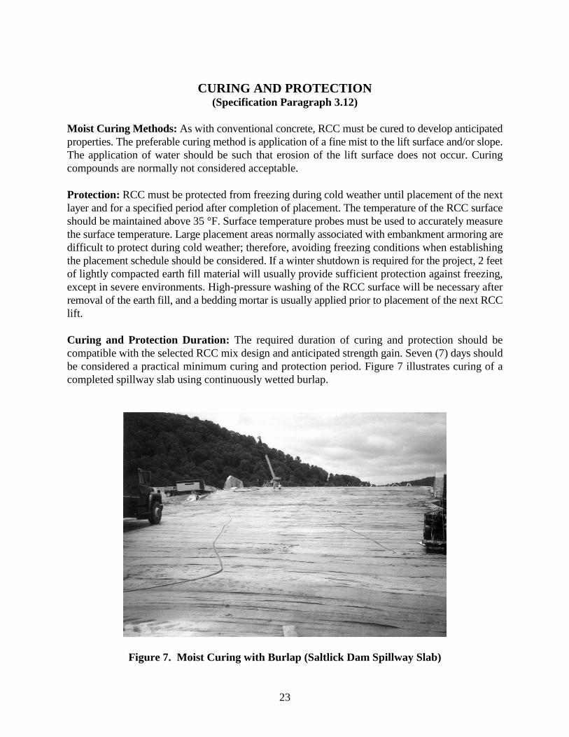
23
CURING AND PROTECTION(Specification Paragraph 3.12)
Moist Curing Methods: As with conventional concrete, RCC must be cured to develop anticipatedproperties. The preferable curing method is application of a fine mist to the lift surface and/or slope.The application of water should be such that erosion of the lift surface does not occur. Curingcompounds are normally not considered acceptable.
Protection: RCC must be protected from freezing during cold weather until placement of the nextlayer and for a specified period after completion of placement. The temperature of the RCC surfaceshould be maintained above 35 °F. Surface temperature probes must be used to accurately measurethe surface temperature. Large placement areas normally associated with embankment armoring aredifficult to protect during cold weather; therefore, avoiding freezing conditions when establishingthe placement schedule should be considered. If a winter shutdown is required for the project, 2 feetof lightly compacted earth fill material will usually provide sufficient protection against freezing,except in severe environments. High-pressure washing of the RCC surface will be necessary afterremoval of the earth fill, and a bedding mortar is usually applied prior to placement of the next RCClift.
Curing and Protection Duration: The required duration of curing and protection should becompatible with the selected RCC mix design and anticipated strength gain. Seven (7) days shouldbe considered a practical minimum curing and protection period. Figure 7 illustrates curing of acompleted spillway slab using continuously wetted burlap.
Figure 7. Moist Curing with Burlap (Saltlick Dam Spillway Slab)
24
FACING FINISH TREATMENT(Specification Paragraph 3.13)
General: Exposed RCC has been generally used for the face of overtopping protection or spillwayprojects. The RCC mix must be designed to have sufficient durability and strength to withstandclimatic and hydraulic forces to which it will be subjected. If it is determined that no exposed RCCmix can withstand these forces or may need to be more esthetically appealing, it may be faced withconventional concrete, precast concrete, or a combination of both. Another method of treating thedownstream face that has gained considerable acceptance lately is to cover the RCC with earth andplanted grass.
Expectations: Very few owners of RCC structures own more than one RCC project. The typicalRCC project is sold to an owner as a concrete structure, but, because of construction methods, willbe more economical than conventional concrete. Many owners envision their projects having fairlysmooth textures and the straight lines of conventional concrete, only to be disappointed when theysee the unfinished look of an RCC surface. Prospective owners should be shown examples ofunfaced RCC surfaces and the different methods that have been used to face RCC to increasedurability and to improve appearance. If the owner’s expectations are known at the beginning of thedesign process, certain steps can be taken to improve the finished appearance of unfaced RCC, ifrequired. Mixes with a high paste volume and finer aggregate gradation can be used to fill surfacevoids, minimize segregation, and reduce the occurrence of rock pockets.
Selection Criteria: Facing system selection is site specific and should consider the intended purposeof the facility, local climatic conditions, materials availability, dam size, and owner preferences. Anoverview of the various facings systems that have been used, including assessments of performanceof each type of system, is presented herein. Guidelines are also provided for selection of theappropriate systems with consideration for constructibility, durability, appearance, and cost.Although the type of facing system selected is site specific and is based on a number of criteria, allsuccessful facing systems for RCC have one feature in common—they should not impede the highproduction rates of RCC placement. This should always be a consideration in selecting a facingsystem for an RCC project.
Available Facing Options: The selection of the downstream RCC facing system is primarilyconcerned with constructibility, aesthetics, and sometimes energy dissipation of overtopping flows.Here again the designer must consider the intended purpose of the facility, local climatic conditions,materials availability, dam size and shape, and owner preferences. Typical sections of the five mostcommon downstream facing systems used in the construction of RCC dams are presented in Figure8. Each of these facing systems is discussed below.
Unformed RCC. An unformed RCC face generally can be constructed on RCC dams where thedownstream slope is flatter than 0.8H:1.0V. To improve constructibility, or when natural roundedaggregates are used, a slope of 0.85H:1.0V, or flatter, should be considered. Steeper slopes requiredownstream forms to maintain the slope as the natural angle of repose of the RCC mix is exceeded.The angle of repose of an RCC mix mainly depends on the shape and grading of the aggregates, and
25
mix workability. When using an unformed RCC face, the face is normally overbuilt 1 to 2 feet forlong-term loss of RCC due to weathering. This allowance accounts for the fact that it is difficult toachieve a high degree of compaction on the exposed RCC slope, resulting in lower density and lowerstrength at the face. As weathering progresses and the weaker, less dense RCC is removed, thestronger, more dense RCC is exposed. Attempts to compact the exposed slope have includedmotorized hand compactors, running the wheels of heavy equipment along the outer edge, and usingspecially designed compaction equipment mounted on hydraulic tractors.
During construction, spillage over the downstream face is expected to occur, which will result in anaccumulation of loose uncompacted RCC at the face and along the toe. It will probably have littleor no cemented value.
A common feature of RCC faces that have been constructed with an unformed downstream face isthe emergence of vegetation on the face after several years. The vegetation can be especially prolificand dense where the face is kept wet from seepage or surface runoff.
Public and owner perception of the exposed RCC face must also be considered when using thisfacing system. Even though the RCC section is designed to accept loss of some of the downstreamface through weathering, public and/or owner perception of the rough concrete surface may drawunnecessary criticism and alarm.
Formed RCC. Use of forms to construct the downstream face has primarily been employed wherethe downstream RCC slope is steeper than 0.8H:1.0V, and/or where a stepped surface is desired forenergy dissipation of overtopping flows or for appearance. To improve the density and surfaceappearance at the formed RCC face, a wedge of bedding mix can be placed against the downstreamform prior to placing the RCC. The dozer operator can spread the RCC against the form in a mannerthat causes the bedding mix to ride up the face of the form. If the RCC is then carefully compacted,the texture of the finished face can approach that of conventional concrete.
Unreinforced concrete placed concurrently with RCC. This facing system is very similar to theformed RCC facing system, except that a strip of unreinforced conventional concrete 2 to 3 feet wideis placed against the downstream form prior to placing and compacting the RCC. The RCC is spreadand compacted into the conventional concrete. The conventional concrete face is generally moredurable and attractive than a formed RCC face. If the formed steps are left exposed afterconstruction, the tread of the step can be sloped to prevent water from ponding on the steps. Adisadvantage of this system is that it can be difficult to coordinate delivery and placement of the twodifferent concrete materials.
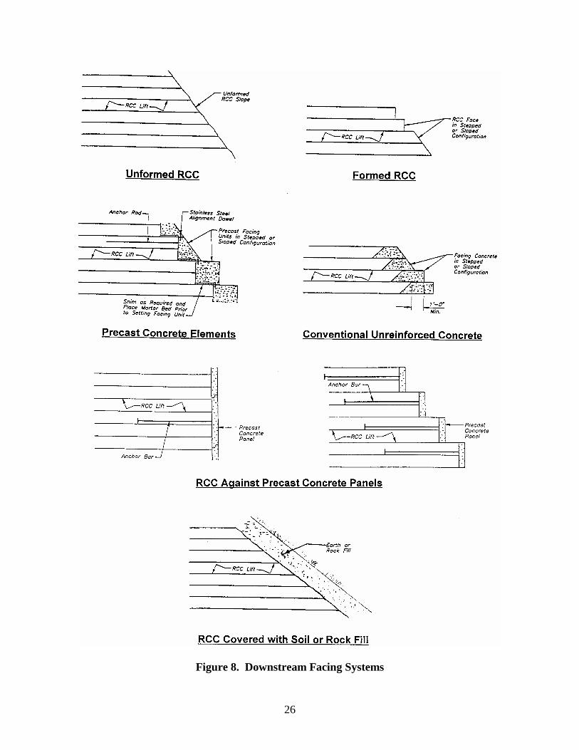
26
Figure 8. Downstream Facing Systems
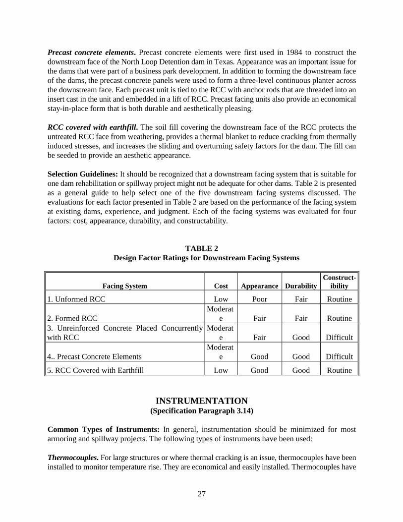
27
Precast concrete elements. Precast concrete elements were first used in 1984 to construct thedownstream face of the North Loop Detention dam in Texas. Appearance was an important issue forthe dams that were part of a business park development. In addition to forming the downstream faceof the dams, the precast concrete panels were used to form a three-level continuous planter acrossthe downstream face. Each precast unit is tied to the RCC with anchor rods that are threaded into aninsert cast in the unit and embedded in a lift of RCC. Precast facing units also provide an economicalstay-in-place form that is both durable and aesthetically pleasing.
RCC covered with earthfill. The soil fill covering the downstream face of the RCC protects theuntreated RCC face from weathering, provides a thermal blanket to reduce cracking from thermallyinduced stresses, and increases the sliding and overturning safety factors for the dam. The fill canbe seeded to provide an aesthetic appearance.
Selection Guidelines: It should be recognized that a downstream facing system that is suitable forone dam rehabilitation or spillway project might not be adequate for other dams. Table 2 is presentedas a general guide to help select one of the five downstream facing systems discussed. Theevaluations for each factor presented in Table 2 are based on the performance of the facing systemat existing dams, experience, and judgment. Each of the facing systems was evaluated for fourfactors: cost, appearance, durability, and constructability.
TABLE 2Design Factor Ratings for Downstream Facing Systems
Facing System Cost Appearance DurabilityConstruct-
ibility
1. Unformed RCC Low Poor Fair Routine
2. Formed RCCModerat
e Fair Fair Routine3. Unreinforced Concrete Placed Concurrentlywith RCC
Moderate Fair Good Difficult
4.. Precast Concrete ElementsModerat
e Good Good Difficult
5. RCC Covered with Earthfill Low Good Good Routine
INSTRUMENTATION(Specification Paragraph 3.14)
Common Types of Instruments: In general, instrumentation should be minimized for mostarmoring and spillway projects. The following types of instruments have been used:
Thermocouples. For large structures or where thermal cracking is an issue, thermocouples have beeninstalled to monitor temperature rise. They are economical and easily installed. Thermocouples have
28
been placed in the aggregate stockpiles to help better manage the withdrawal of the aggregate forRCC mix temperature control.
Piezometers. Piezometers have been installed beneath spillway slabs to measure uplift pressures. Ifthe structure is designed for “full uplift,” the data is primarily of academic interest and theinstruments could be eliminated, thereby avoiding additional project costs. If the structure isdesigned for less than “full uplift,” piezometers may be required to verify that the project isperforming as intended.
Monuments and measuring pins. Monuments and measuring pins have been installed to monitorstructure movement and to determine long-term material loss resulting from either freeze-thawdeterioration or erosion. These provide information for performance evaluation and for schedulingfuture maintenance.
Conflicts with RCC Placement: All of the instruments previously described can be installed withminimal or no impact on RCC placement if proper instruments are selected and an acceptableconstruction sequence is adopted.
STRUCTURAL TOLERANCES(Specification Paragraph 3.15)
Line and grade tolerances for completed RCC surfaces need to be realistic considering the meansand methods used in RCC construction. Tight survey controls will minimize major defects, butstraight lines and grades should not be expected. The specifications should be written to require asturdy forming system that will prevent bulges in steps and other exposed faces due to the dynamiccompaction adjacent to the forms.
QUALITY CONTROL AND TESTING(Specification Paragraph 3.16)
General: Although quality control responsibility for many small projects is often assignedcompletely to the contractor, the engineer and contractor should work together to develop anacceptable and project specific Quality Control Program. The contractor’s daily costs during RCCplacement are relatively high compared to other project activities; therefore, the program should bewell defined in advance of the start of placement, including required action(s) when failing testsoccur. The party responsible for performing each test or activity should be defined in thespecifications. The responsibility may depend on the party responsible for developing the RCC mixdesign(s). See Section titled “MIX DESIGNS” for more discussion on this issue.
Contractor Responsibility: Certain activities such as concrete plant calibration, concrete plantcontrol, scale calibration, and testing of compaction equipment should always be the responsibilityof the contractor. Additional quality control responsibility beyond these “core activities” may alsobe assigned to the contractor. However, where available contractors are unfamiliar with RCC,
29
particularly on small projects, it may be beneficial for the owner or design engineer to perform someof the tests and inspections that would normally be assigned to the contractor on a larger project.
Owner Responsibility: The owner, or the owner’s designated representative, is typically responsiblefor performing some of the quality control testing and all quality assurance activities. This work istypically assigned to the design engineer or a construction manager engaged by the owner.
Engineer Responsibility: Design engineers are responsible for the design and performance of theproject regardless of their responsibility for quality control and testing during construction.Accordingly, it is often in the designer’s interest to be actively involved through all phases ofconstruction. (Note: It is the authors’ opinion that it is also in the owner’s interest to have the designengineer actively involved with quality control and assurance during construction. The designerunderstands the intent of the design and is better suited to assist the owner with critical decisions,particularly when problems arise.) If the design engineer develops the RCC mix design(s) it maybe in his best interest to also perform testing during construction to confirm that project designcriteria have been met, rather than leaving the testing to someone who, when working for thecontractor, may be influenced by production goals.
QC Program Modification: The quality control program should be developed with flexibility topermit modification of the program in response to observed conditions or changes in schedule.
LABORATORY AND TESTING FACILITIES
Laboratory and testing equipment requirements will vary depending on the size and complexity ofthe project. As a minimum, equipment and facilities should be provided on-site for in-place densitytesting and moisture content testing, as well as preparing and molding and curing of cylinders forcompressive strength testing. Equipment for determining gradation of aggregates is also desirablebut not essential if aggregates are provided by a reliable commercial producer and if tests areperformed on the material by an independent laboratory.
MEASUREMENT AND PAYMENT(Specification Part 4)
General: Measurement and payment for RCC placed in embankment armoring or spillway projectsmay be on either a lump sum or unit price basis. In most projects, unit price basis is the preferredmethod because it allows more flexibility to make changes to the design mix.
Unit Price Contracts: If variation in quantities is anticipated, a unit price contract provides thegreatest flexibility. Many contracts are written with provisions for unit price adjustments if quantitieschange more than 15% or 20%, while other contracts do not permit such change under anycircumstances. The engineer should assess the potential for quantity changes and determine if suchprovisions are appropriate. When unit price contracts are used, the need for individual payment itemsfor aggregates; cement; pozzolan (if used); mixing, conveying, and placing RCC; trial placement;

30
bedding mix; contraction joints; and winter protection (if required) should be assessed and includedin the bid documents as appropriate.
Lump Sum Contracts: Lump sum contracts are best used where little or no variation in quantitiesis anticipated. However, lump sum contracts can also be used in cases where quantities may vary,provided that supplemental or contingent payment items are included in the contract for those itemsthat are expected to vary in quantity. Descriptions of contingent or supplemental pay items shouldbe provided in the bid documents.