Embed Size (px)
Citation preview

IntroductionUnifrax’s FyreWrap® Elite® 1.5 Duct Insulation is a two-layerflexible enclosure for both one- and two-hour rated commercialkitchen grease ducts. FyreWrap Elite 1.5 Duct Insulation istested per CAN/ULC-S144 and is acceptable as an alternateto a traditional fire-rated shaft. Installed as a two-layersystem, FyreWrap Elite 1.5 complies with NFPA 96 and the2005 and 2010 National Building Code of Canada. FyreWrapElite 1.5 Duct Insulation offers the following product features:• 2-hour fire-resistance rating• Alternate to shaft enclosure• Complies with NFPA 96 and the 2005 and 2010 National
Building Code of Canada• Meets CAN/ULC-S144• Two-layer system; inner layer utilizes butt joint • High-temperature, biosoluble insulation• Zero clearance to combustibles, at any location • GREENGUARD listed for Microbial Resistance
FyreWrap® Elite® 1.5Duct Insulation – Grease Duct Canadian System
Typical Product PropertiesNFPA 96 ................................................................................CompliesIntertek Laboratories (WH) ....................................................Listed, File 14870ASTM E2336 ..........................................................................Duct System: Design No. UNI/BI 120-02, UNI/WA 120-01CAN/ULC-S144 ......................................................................Duct System: Design No. UNI/BI 120-03
........................................................................................Stability – 2 hour
........................................................................................Integrity – 2 hour
........................................................................................Insulation – 2 hourASTM E84, UL 723, ULC S102.2 – UL File No. R14514 Unfaced Blanket Encapsulated
Flame Spread/Smoke Developed Rating........................Zero/Zero <25/<50ASTM E814 Firestop Test ......................................................Firestop System: UNI/FRD 120-19, UNI/BI 120-02,
F-Rating = 2 Hrs., T-Rating = 2 Hrs., H-Rating = 2 Hrs. UNI/BI 120-03ASTM E136 Non-Combustibility Test ......................................PassesASTM C518 Durability Test ....................................................Passes; R-Value = 4.8 per inch at 75°FASTM C518 Thermal Resistance ..........................................R-Value of Elite 38mm (11⁄2") = 7.2ASTM D6329-03 Microbial Resistance ..................................Highly Resistant to Mold Growth
Complies with: NFPA 96 (all editions), 2005 and 2010 National Building Code of Canada, NFPA 90 A (2002).
FyreWrap® Elite® 1.5 Duct Insulation
Product ComponentsCore Material: FyreWrap Elite 1.5 incorporates Insulfrax®
Thermal Insulation as its core material. Insulfrax is a high-temperature insulation made from a calcia, magnesia, silicachemistry designed to enhance biosolubility. It providesexcellent insulation in a noncombustible blanket product form.
Encapsulating Material: The core insulation blanket iscompletely encapsulated in an aluminum foil fiberglassreinforced scrim covering. This scrim provides additionalhandling strength as well as protection from moistureabsorption and tearing.
Complieswith:
Product Information Sheet

Typical Product ParametersThickness 38mm (11⁄2")Nominal Density 96kg/m3 (6 pcf)Standard Product Form Scrim EncapsulatedProduct Availability 610mm x 7.6m (24"w x 25LF)
1219mm x 7.6m (48"w x 25LF)
InstallationThe FyreWrap Elite 1.5 Duct Insulation Canadian Systemconsists of a fully encapsulated, two-layer system applieddirectly to the duct surface. The insulation system may beinstalled at zero clearance to combustibles at any point. Tominimize waste, FyreWrap Elite 1.5 should be rolled out tautlybefore measuring and making any material cuts.
Butt Joint Both Layers Wrap Option (For ducts 610mm (24") x 610mm (24") or less)For ducts 610mm (24") x 610mm (24") or less, both layers of wrap can be installed with transverse (perimeter) jointsbutted and minimum 76mm (3") longitudinal overlaps locatedon the topside of horizontal ducts. Stagger transverse buttjoints by 305mm (12") between the first and second layers of wrap. Both layers of wrap can be temporarily secured with25mm (1") wide filament tape. After the second layer of wrap
is installed, place carbon or stainless steel bands (min. 13mm (1⁄2") wide, 0.4mm (.015") thick) on both sides of alltransverse butt joints 64mm (21⁄2") from the joint and in thefield area between the butt joints, 229mm (9") on center.Tighten banding to firmly hold the wrap system in place butnot so tight as to cut or damage the blanket and secure withminimum 25mm (1") long steel crimp clips. Seal all secondlayer transverse butt joints and exposed blanket edges withminimum 76mm (3") wide aluminum foil tape. Pins are NOTrequired when utilizing this installation method.
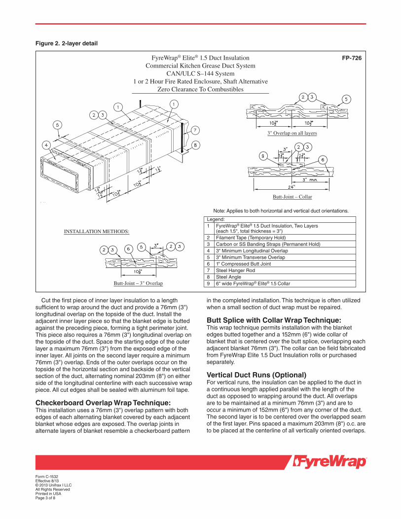
Overlap TechniquesThe first layer can be installed with transverse (perimeter)joints butted and minimum 76mm (3") longitudinal overlapson the topside of horizontal ducts. All overlaps for thesecond, or outer layer, are required to be a minimum of76mm (3"). For the second layer, transverse (perimeter)overlaps of adjacent blankets may be installed using one ofthe following three methods and as shown in Figure 2.
Telescoping Overlap Wrap Technique:This wrap technique is the most common method of installingFyreWrap Elite 1.5 where each adjacent blanket has oneedge exposed and one edge covered by the next blanket, to form a 76mm (3") overlap.
Form C-1532Effective 8/13© 2013 Unifrax I LLCAll Rights ReservedPrinted in USAPage 2 of 8
Figure 1. Butt Joint Wrap Option
Legend:1 FyreWrap® Elite® 1.5 Duct Insulation, Two Layers
(each 1.5", total thickness = 3")2 Filament Tape (Temporary Hold)3 1⁄2" Carbon or SS Banding Straps (Permanent Hold)4 3" Minimum Longitudinal Overlap5 1" Compressed Butt Joint6 3" Wide Aluminum Foil Tape at Transverse Butt Joints
FyreWrap® Elite® 1.5 Duct InsulationCommercial Kitchen Grease Duct System
1 and 2 Hour Fire-Rated Enclosure, Shaft Alternative Zero Clearance To Combustibles
Intertek Design No. UNI/BI 120-02Butt Joint System (Both Layers, Max 24"x24" Duct)
FP-736
Note: Applies to both horizontal and vertical duct orientations.
INSTALLATION METHOD:
Butt-JointAdjacent Blanket Pieces
Form C-1532Effective 8/13© 2013 Unifrax I LLCAll Rights ReservedPrinted in USAPage 3 of 8
Figure 2. 2-layer detail
Cut the first piece of inner layer insulation to a lengthsufficient to wrap around the duct and provide a 76mm (3")longi tu dinal overlap on the topside of the duct. Install theadjacent inner layer piece so that the blanket edge is buttedagainst the preceding piece, forming a tight perimeter joint.This piece also requires a 76mm (3") longitudinal overlap onthe topside of the duct. Space the starting edge of the outerlayer a maximum 76mm (3") from the exposed edge of theinner layer. All joints on the second layer require a minimum76mm (3") overlap. Ends of the outer overlaps occur on thetopside of the horizontal section and backside of the verticalsection of the duct, alternating nominal 203mm (8") on eitherside of the longitudinal centerline with each successive wrappiece. All cut edges shall be sealed with aluminum foil tape.
Checkerboard Overlap Wrap Technique:This installation uses a 76mm (3") overlap pattern with bothedges of each alternating blanket covered by each adjacentblanket whose edges are exposed. The overlap joints inalternate layers of blanket resemble a checkerboard pattern
in the completed installation. This technique is often utilizedwhen a small section of duct wrap must be repaired.
Butt Splice with Collar Wrap Technique:This wrap technique permits installation with the blanketedges butted together and a 152mm (6") wide collar ofblanket that is centered over the butt splice, overlapping eachadjacent blanket 76mm (3"). The collar can be field fabricatedfrom FyreWrap Elite 1.5 Duct Insulation rolls or purchasedseparately.
Vertical Duct Runs (Optional)For vertical runs, the insulation can be applied to the duct ina continuous length applied parallel with the length of theduct as opposed to wrapping around the duct. All overlapsare to be maintained at a minimum 76mm (3") and are tooccur a minimum of 152mm (6") from any corner of the duct.The second layer is to be centered over the overlapped seamof the first layer. Pins spaced a maximum 203mm (8") o.c. areto be placed at the centerline of all vertically oriented overlaps.
Legend:1 FyreWrap® Elite® 1.5 Duct Insulation, Two Layers
(each 1.5", total thickness = 3")2 Filament Tape (Temporary Hold)3 Carbon or SS Banding Straps (Permanent Hold)4 3" Minimum Longitudinal Overlap5 3" Minimum Transverse Overlap6 1" Compressed Butt Joint7 Steel Hanger Rod8 Steel Angle9 6" wide FyreWrap® Elite® 1.5 Collar
FyreWrap® Elite® 1.5 Duct InsulationCommercial Kitchen Grease Duct System
CAN/ULC S–144 System1 or 2 Hour Fire Rated Enclosure, Shaft Alternative
Zero Clearance To Combustibles
3" Overlap on all layers
FP-726
Note: Applies to both horizontal and vertical duct orientations.
INSTALLATION METHODS:
Butt-Joint – 3" Overlap
Butt-Joint – Collar
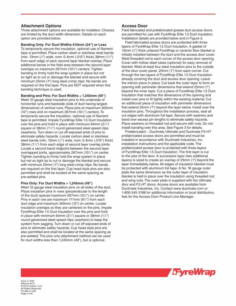
Attachment OptionsThree attachment options are available for installers. Choicesare limited by the duct width dimension. Details on eachoption are provided below.
Banding Only: For Duct Widths 610mm (24") or Less To temporarily secure the insulation, optional use of filamenttape is permitted. Place carbon steel or stainless steel bands(min. 13mm (1⁄2") wide, nom. 0.4mm (.015") thick) 38mm (11⁄2")from each edge of each second layer blanket overlap. Placeadditional bands in the field area between the second layeroverlaps on maximum 267mm (101⁄2") centers. Tightenbanding to firmly hold the wrap system in place but not so tight as to cut or damage the blanket and secure withminimum 25mm (1") long steel crimp clips. No bands arerequired on the first layer. Pins are NOT required when thisbanding technique is used.
Banding and Pins: For Duct Widths ≤ 1,245mm (49")Weld 12-gauge steel insulation pins to the underside ofhorizontal runs and backside (side of duct having largestdimensions) of vertical runs. Place pins at maximum 305mm(12") rows and on maximum 267mm (101⁄2") centers. Totemporarily secure the insulation, optional use of filamenttape is permitted. Impale FyreWrap Elite 1.5 Duct Insulationover the pins and hold in place with minimum 64mm (21⁄2")square or 38mm (11⁄2") round galvanized steel speed clips(washers). Turn down or cut off exposed ends of pins toeliminate safety hazards. Locate carbon steel or stainlesssteel bands (min. 13mm (1⁄2") wide, nom. 0.4mm (.015") thick)38mm (11⁄2") from each edge of second layer overlap joints.Locate a second band midpoint between the second layerover lapped joints, approximately 267mm (101⁄2") on center.Tighten banding to firmly hold the wrap system in place but not so tight as to cut or damage the blanket and securewith minimum 25mm (1") long steel crimp clips. No bands are required on the first layer. Cup head style pins are alsopermitted and shall be located at the same spacing as pre-welded pins.
Pins Only: For Duct Widths > 1,245mm (49")Weld 12-gauge steel insulation pins on all sides of the duct.Place insulation pins in rows (perpendicular to the length of the duct) spaced maximum 267mm (101⁄2") on center. Pins in each row are maximum 171mm (63⁄4") from each duct edge and maximum 305mm (12") on center. Locateinsulation overlaps so they are centered on the pins. ImpaleFyreWrap Elite 1.5 Duct Insulation over the pins and hold in place with minimum 64mm (21⁄2") square or 38mm (11⁄2")round galvanized steel speed clips (washers) to keep thesystem from sagging. Turn down or cut off exposed ends ofpins to eliminate safety hazards. Cup head style pins are also permitted and shall be located at the same spacing aspre-welded. The pins only attachment method can be usedfor duct widths less than 1,245mm (49"), but is optional.
Access DoorField fabricated and prefabricated grease duct access doorsare permitted for use with FyreWrap Elite 1.5 Duct Insulation.Installation details are provided below and in Figure 3.
Field fabricated access doors are protected with threelayers of FyreWrap Elite 1.5 Duct Insulation. A gasket of13mm (1⁄2") thick unfaced FyreWrap or ceramic fiber blanket isinitially installed between the duct and the access door cover.Weld threaded rod to each corner of the access door opening.Cover with hollow steel tubes (optional) for easy removal ofblanket. Weld at least four steel insulation pins to the outsideof the door cover panel, 25mm (1") from each corner. Cutthrough the two layers of FyreWrap Elite 1.5 Duct Insulationalready covering the duct and access door opening. Leavethe interior piece in place. Cut back the outer layer to form anopening with perimeter dimensions that extend 25mm (1")beyond the inner layer. Cut a piece of FyreWrap Elite 1.5 DuctInsulation that matches the dimensions of the opening andinstall over pins to fit tightly within the existing material. Cutan additional piece of insulation with perimeter dimensionsthat extend 25mm (1") beyond the layer below. Install over theinsulation pins. Throughout the installation process, seal allcut edges with aluminum foil tape. Secure with washers andbend over excess pin lengths to eliminate safety hazards.Place washers on threaded rod and secure with nuts. Do notinstall banding over this area. See Figure 3 for details.
Prefabricated – Ductmate Ultimate and Ductmate F2-HTprefabricated access doors are permitted and must beinstalled in accordance with Ductmate Industries, Inc.installation instructions and the applicable code. Theprefabricated access door is protected with three layers of FyreWrap Elite 1.5 Duct Insulation. The first layer is cut to the size of the door. A successive layer (two additionallayers) is sized to create an overlap of 25mm (1") beyond thelayer immediately below. All edges of insulation blanket mustbe protected with aluminum foil tape. A No. 16 gauge outerplate the same dimension as the outer layer of insulationblanket is held in place over the insulation using threaded rodand wing nuts. The outer plate is supplied with the Ultimate door and F2-HT doors. Access doors are available fromDuctmate Industries, Inc. Contact www.ductmate.com or 1-800-245-3188 for additional information or local distributors.Ask for the Access Door Product Line Manager.
Form C-1532Effective 8/13© 2013 Unifrax I LLCAll Rights ReservedPrinted in USAPage 4 of 8

Duct SupportHorizontal duct support systems do not require FyreWrapinsulation when constructed using a minimum 10mm (3⁄8")diameter uninsulated all-thread steel rod and 38mm x 38mmx 3mm (11⁄2" x 11⁄2" x 1⁄8") uninsulated steel angle spaced amaximum 1524mm (60") on center along the length of theduct. A minimum clearance of 25mm (1") is required betweenthe protected duct and the steel rod. To increase hangerspacing to 1829mm (72") on center, 13mm (1⁄2") all-thread steel rod and 51mm x 51mm x 6mm (2" x 2" x 1⁄4") steel angleare required. Vertical duct support systems do not requireFyreWrap insulation when constructed using minimum 38mmx 38mm x 6mm (11⁄2" x 11⁄2" x 1⁄4") steel angle brackets locatedon opposite sides of the duct, on the top and bottom of eachfloor-ceiling assembly. The supports are attached to the ductwith welds. Maximum spacing between vertical supports shall be established by structural calculations in accordancewith the applicable code, that are submitted to the buildingofficial for approval. See Figure 4 for details. For all other
Form C-1532Effective 8/13© 2013 Unifrax I LLCAll Rights ReservedPrinted in USAPage 5 of 8
duct sup port configurations, please contact Unifrax at 1-800-635-4464 and ask for Fire Protection ApplicationEngineering.
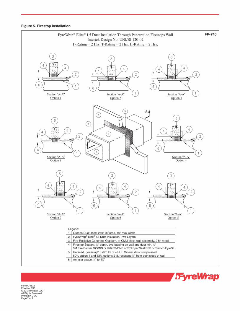
Firestop SystemsWhere ducts insulated with FyreWrap Elite 1.5 DuctInsulation pass through fire-rated walls and floors, thepenetration opening shall be firestopped to maintain the fire rating of the assembly. Firestop Systems acceptable for use with FyreWrap Elite 1.5 Duct Insulation ASTM E2336 System at the time of printing are detailed below. See Figures 5-7 for details. Additional firestop systems may be developed and available for use. Contact Unifrax at 1-800-635-4464 and ask for Fire Protection ApplicationEngineering for additional details and assistance or visit the test lab web site for the latest documentation.
Figure 3. Access Door
FyreWrap® Elite® 1.5 Duct InsulationCommercial Kitchen Grease Duct System
Access Door Systems
Legend:1 Access Door Opening2 All Thread Rods3 Access Door Cover Panel 16 Gauge (field fab. only)4 Insulation Pins – Welded to Cover5 First Layer FyreWrap® Elite® 1.5 6 Second Layer FyreWrap® Elite® 1.5, 1" Overlap7 Third Layer FyreWrap® Elite® 1.5, 1" Overlap8 Speed Clips/Washers9 Cut Edges Sealed With Aluminum Foil Tape
10 Spool pieces for threaded rods (optional field fab. only)11 Wing Nuts12 Washers13 Insulation plate14 Ceramic fiber gasket, 1⁄2" thick15 Pre-fabricated access door
Ductmate F2-HTDoor System
Field FabricatedDoor System
Ductmate UltimateDoor System
FP-738

Form C-1532Effective 8/13© 2013 Unifrax I LLCAll Rights ReservedPrinted in USAPage 6 of 8
FyreWrap® Elite® 1.5 Duct Insulation Typical Duct Support Details
TYPICAL HORIZONTAL DUCT SUPPORT DETAILS
TYPICAL VERTICAL DUCT SUPPORT DETAILS
Legend:1 FyreWrap® Elite® 1.5 Duct Insulation, Two Layers2 Duct Support Mechanism 3 Mechanical Fasteners & Washers4 Grease Duct5 Fire Resistive Concrete Floor/Ceiling Assembly6 Firestop System7 Steel Banding and Clips
Figure 4. Firestop Installation
Legend:
1 Max. Duct Size (HxW) 49" x 49" 49" x 49"2 Steel Threaded Rod 3⁄8" diameter 3⁄8" diameter3 Steel Angle 11⁄2" x 11⁄2" x 1⁄8" 2" x 2" x 1⁄4"4 Support System Spacing (L) 60" 72"
FP-739
For additional information about product performance or to identify the recommended product for your fire protectionapplication, please contact Unifrax at 1-800-635-4464 andask for Fire Protection Application Engineering.
Refer to the product Material Safety Data Sheet (MSDS) for recommended work practices and other product safetyinformation.
Form C-1532Effective 8/13© 2013 Unifrax I LLCAll Rights ReservedPrinted in USAPage 7 of 8
FyreWrap® Elite® 1.5 Duct Insulation Through Penetration Firestops Wall Intertek Design No. UNI/BI 120-02
F-Rating = 2 Hrs. T-Rating = 2 Hrs. H-Rating = 2 Hrs.
Legend:1 Grease Duct, max. 2401 in2 area, 49" max width2 FyreWrap® Elite® 1.5 Duct Insulation, Two Layers3 Fire-Resistive Concrete, Gypsum, or CMU block wall assembly, 2 hr. rated4 Firestop Sealant, 5⁄8" depth, overlapping on wall and duct min. 1⁄2"
3M Fire Barrier 1000NS or Hilti FS-ONE or STI SpecSeal SSS or Tremco FyreSil5 Unfaced FyreWrap® Elite® 1.5 or 4 PCF Mineral Wool compressed
50% option 1 and 33% options 2-8, recessed 5⁄8" from both sides of wall6 Annular space, 1⁄2" to 41⁄2"
Figure 5. Firestop Installation
FP-740
Section “A-A”Option 1
Section “A-A”Option 2
Section “A-A”Option 3
Section “A-A”Option 8
Section “A-A”Option 4
Section “A-A”Option 7
Section “A-A”Option 6
Section “A-A”Option 5

FyreWrap® Elite® 1.5 Duct Insulation Through Penetration Firestops Floor/Ceiling Intertek Design No. UNI/BI 120-02
F-Rating = 2 Hrs. T-Rating = 2 Hrs. H-Rating = 2 Hrs.
Legend:1 Grease Duct, max. 2401 in2 area, 49" max width2 FyreWrap® Elite® 1.5 Duct Insulation, Two Layers3 Fire-Resistive Concrete Floor/Ceiling assembly, 2 hr. rated4 Firestop Sealant, 5⁄8" depth, overlapping on floor and duct min. 1⁄2"
3M Fire Barrier 1000NS or Hilti FS-ONE or STI SpecSeal SSS or Tremco FyreSil5 Unfaced FyreWrap® Elite® 1.5 or 4 PCF Mineral Wool compressed
50% option 1 and 33% options 2-8, recessed 5⁄8" from both sides of wall6 Annular space, 1⁄2" to 41⁄2"
Figure 6. Firestop Installation
FP-741
Section “A-A”Option 1
Section “A-A”Option 2
Section “A-A”Option 3
Section “A-A”Option 8
Section “A-A”Option 4
Section “A-A”Option 7
Section “A-A”Option 6
Section “A-A”Option 5
Form C-1532Effective 8/13© 2013 Unifrax I LLCAll Rights ReservedPrinted in USAPage 8 of 8
The following are registered trademarks of Unifrax: FyreWrap, Elite and Insulfrax.
The test data shown are average results of tests conducted under standard procedures and are subject to variation. Results should not be usedfor specification purposes.
Product Information Sheets are periodically updated by Unifrax. Before relying on any data or other information in this Product Information Sheet, you should confirm that it is still current and has not been superseded. A Product Information Sheet that has been superseded may contain incorrect, obsolete and/or irrelevant data and other information.
Unifrax I LLCCorporate Headquarters600 Riverwalk ParkwaySuite 120Tonawanda, NY 14150Telephone: 716-768-6500Canada: 1-800-635-4464Internet: www.unifrax.comEmail: [email protected]