Embed Size (px)
Citation preview

FY'98 Trade Study from Code YGSFC Earth Science Technology Office
Using COTS Components forReal-Time Processing of
SAR Systems
by
Charles Le and Scott Hensley
Final Report
Interferometric Algorithms and System Analysis GroupRadar Science and Engineering Section
Jet Propulsion Laboratory

2
Summary of Research Activities
The research activities are divided into three stages, with each stage lastingapproximately one month. In the first stage 1, we discussed the design trade-off for real-time SAR processing. The objectives are to maximize the processing density(MFLOPS/volume, MFLOPS/weight, MFLOPS/watt), to minimize the hardware cost(MFLOPS/dollar), to minimize the software development cost, and to maximize softwaregenerality. As an example, we briefly described the Mercury's RACEwaymulticomputer as a low cost, high-performance, embedded heterogeneous message-passing multicomputer system.
In the second stage 2, we presented a procedure to divide the SAR signal processinginto pipelined parallel steps that can be performed on a parallel computer. We alsoestimated the throughput, memory, and I/O bandwidth requirements using the NASA/JPLGeoSAR system. Using again the Mercury's RACEway multicomputer as an example,we showed how to configure the hardware for SAR signal processing.
Parallel programming was the topic in this final stage 3. First, we gave an overviewof the standard multicomputing platforms and parallel programming models. We thencompared and contrasted "scientific" versus "real-time" processing/programming. Next,we showed the hardware/software co-design approach for SAR signal processing. Then,we discussed the current issues in parallel programming. Finally, we described a typicalsoftware architecture for parallel programming of SAR signal processing.

3
Part I: The Design Trade-Off for Real-Time SAR Processing
1. Introduction to Parallel Processing
Multiprocessing is necessary to meet the real-time demands, and/or high I/O data rate,and/or computationally intensive algorithms, typically found in radar/sonar systems.The four key issues in large multiprocessor systems are architecture, communicationefficiency, reliability, and ease of use 4. Usually, parallel architectures are characterizedby two general classes: shared-memory multiprocessors and message-passingmulticomputers 5. The main differences lie in the implementation of memory sharingand interprocessor communication. In a shared-memory multiprocessor configuration,all processors within the system have equal access to a shared-memory address space.The interprocessor communication is achieved by modifying data in the shared-memoryaddress space. On the other hand, in the message-passing multicomputer architecture,each compute node (CN) consists of a processor and its own local memory, unsharedwith all other CN's. CN's are connected with each other via a common high-speed datacommunication fabric or interconnection network. Processors communicate with eachother by passing messages through this interconnection network.
2. A Typical Example: The Mercury's RACEway Multicomputer
In recent years, Mercury Computer Systems, Inc. (MCSI) has emerged as one of theleaders in the development and manufacturing of lower cost, high-performance,embedded heterogeneous message-passing multicomputer systems. These parallelsystems address complex real-time applications requiring tremendous computationalthroughputs (such as radar/sonar processing, medical imaging, etc.). Its maincompetitors include, but not limited to, Alacron, CSPI, and Sky Computers 6. However,MCSI's hardware systems dominate the radar/sonar market in both military 7 8 9 andcommercial 10 11 12 sectors. MCSI's RACE multicomputer provides a foundation forparallel systems and offers a set of building blocks that provide upward scalability 13 14.An example of high-level heterogeneous RACE multicomputer is shown in Fig. 1. Thesystem consists of programmable digital signal processors (DSPs), such as the AnalogDevices' SHARC chips; general-purpose reduced-instruction-set-computing (RISC)microprocessors, such as the Intel's i860, Motorola/IBM's PowerPC; application-specific-integrated-circuit devices, such as Xilinx's field-programmable-gated-array(FPGA) XC4000 series; I/O ports; and a network interface all connected via theRACEway interconnection network. The RACEway interconnection network is theframework used to provide high-performance communications among the interconnectedprocessors and devices. Each node in the multicomputer interfaces the network throughthe RACE network chip (see Fig. 2). The network chip is the key to the highperformance and low cost of the RACE system. The network chip is a crossbar with 6I/O channels consisting of 32 bit datapaths, and 8 bits of control and clocking. Eachchannel is bi-directional. This device can handle three simultaneous transfers of 160MB/s for a total of 489 MB/s, and can broadcast to 5 ports at 640 MB/s. The RACE

4
RACEway Chip
Po P1
Co C1 C2 C3
Parent Ports
Child Ports
RACEway Interconnection Network
RISC Memory NetworkInterface
I/ODSP
VME Bus
PCI Bus
network can be configured into a wide variety of network topologies; however, the mostcommon configuration is a fat-tree architecture 13.
Figure 1: The RACE Multicomputer 13
Figure 2: The RACE network chip 13
5
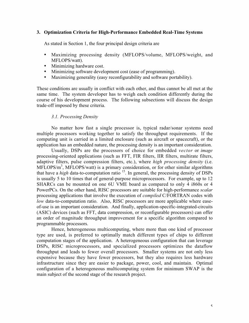
3. Optimization Criteria for High-Performance Embedded Real-Time Systems
As stated in Section 1, the four principal design criteria are
• Maximizing processing density (MFLOPS/volume, MFLOPS/weight, andMFLOPS/watt).
• Minimizing hardware cost.• Minimizing software development cost (ease of programming).• Maximizing generality (easy reconfigurability and software portability).
These conditions are usually in conflict with each other, and thus cannot be all met at thesame time. The system developer has to weigh each condition differently during thecourse of his development process. The following subsections will discuss the designtrade-off imposed by these criteria.
3.1. Processing Density
No matter how fast a single processor is, typical radar/sonar systems needmultiple processors working together to satisfy the throughput requirements. If thecomputing unit is carried in a limited enclosure (such as aircraft or spacecraft), or theapplication has an embedded nature, the processing density is an important consideration.
Usually, DSPs are the processors of choice for embedded vector or imageprocessing-oriented applications (such as FFT, FIR filters, IIR filters, multirate filters,adaptive filters, pulse compression filters, etc.), where high processing density (i.e.MFLOPS/m3, MFLOPS/watt) is a primary consideration, or for other similar algorithmsthat have a high data-to-computation ratio 15. In general, the processing density of DSPsis usually 5 to 10 times that of general-purpose microprocessors. For example, up to 12SHARCs can be mounted on one 6U VME board as compared to only 4 i860s or 4PowerPCs. On the other hand, RISC processors are suitable for high-performance scalarprocessing applications that involve the execution of compiled C/FORTRAN codes withlow data-to-computation ratio. Also, RISC processors are more applicable where ease-of-use is an important consideration. And finally, application-specific-integrated-circuits(ASIC) devices (such as FFT, data compression, or reconfigurable processors) can offeran order of magnitude throughput improvement for a specific algorithm compared toprogrammable processors.
Hence, heterogeneous multicomputing, where more than one kind of processortype are used, is preferred to optimally match different types of chips to differentcomputation stages of the application. A heterogeneous configuration that can leverageDSPs, RISC microprocessors, and specialized processors optimizes the dataflowthroughput and leads to fewer overall processors. Smaller systems are not only lessexpensive because they have fewer processors, but they also requires less hardwareinfrastructure since they are easier to package, power, cool, and maintain. Optimalconfiguration of a heterogeneous multicomputing system for minimum SWAP is themain subject of the second stage of the research project.

6
3.2. Hardware Cost
Driven by profit, business decision places strong emphasis on this criterion.However, it is less important during the development stage or in situation where largeproduction volume is not an issue. In a typical research establishment, system reliabilitymay be more relevant. Thus, the optimal system with respect to hardware cost dependsonly on the budget for a specific project. Fortunately, use of COTS-based components(almost) always ensure parts availability in a competitive market. Also, with aheterogeneous system, system cost can be substantially reduced by matching theprocessor type to the processing requirement.
3.3. Software Cost
This is the most important design criterion when developing a prototype or proof-of-concept system. In these situations, the applications require only one workingprototype and a spare copy of such system. Most of the time will be spent on softwaredeveloping. Minimizing software cost leads to choosing the processors that are easy toprogram, or have strong third-party support 16, or benefited from academia and federallyfunded research 17.
In the past, general-purpose microprocessors were the easiest to program due totheir available high-level language (such as FORTRAN or C) compiler. ProgrammingDSPs, on the other hand, was much harder, primarily through libraries and excruciatinglytailored hand code. However, progress in the compiler and architecture has made itpossible for the DSP's applications to be written in a high-level language, and to allowthe compiler to do the fine-grain scheduling necessary to achieve available instructionlevel parallelism 18 19. All of the currently popular DSPs possess at least a C compilerprovided by their manufacturer. And most of DSP board vendors often include third-party high-level language compiler and real-time-operating-system (RTOS) for theirboards.
If the application calls for a heterogeneous architecture, then interprocessorcommunication becomes important. Here, an open software infrastructure is necessary toenable seamless integration of different processor types, operating systems, andapplication programming interfaces, allowing rapid response to new technologies andapplication-specific software requirements. Development tools such as debuggers andapplication building tools are also of importance.
3.4. System Generality
System generality refers to the openness of the hardware architecture, and theease with which different applications can be implemented on a given multicomputer.Open hardware architecture reduces life-cycle costs by providing a standard platform forfuture upgrades. Open and standard interfaces permit third-parties and end-users to addtheir new and unique I/O and specialized processing elements for a wide range ofapplication requirements. COTS-based open-architecture multicomper systems can
7
rapidly adapt and evolve to new technology and requirements. The marketplace willprovide the best technology available on an open (and standard) system, thus extendingthe useful life cycle of the systems for many years.
As already discussed in Section 4.3, an open software architecture is alsopreferred so that software modifications or upgrades can be easily ported to a givenhardware system.
4. Summary
In this first part, we have presented and discussed the design trade-off one must facewhen designing a real-time computing platform for SAR signal processing. Pastapproach centered on choosing "the right processor". Advanced technology made itpossible for open heterogeneous COTS-based multicomputing systems that allow severaltypes of processors to work in parallel. The main idea is to optimally match each type ofprocessors to the computation stages where it can provide the best throughput. Coupledwith an open software infrastructure, these systems offer significant advantages andreduce overall system cost.

8
Part II: Pipelined Parallel Architecture for SAR Processor
1. Introduction
In this part, we present a procedure to divide the SAR signal processing into pipelinedparallel steps that can be performed on a parallel computer. We also estimate thethroughput, memory, and I/O bandwidth requirements using the NASA/JPL GeoSARsystem 20 21 22. Using again the Mercury's RACEway multicomputer 14 as an example,we show how to configure the hardware for SAR signal processing.
SAR is a radar imaging technique aiming at providing two-dimensional high-qualityhigh-resolution images for terrain mapping at target imaging. Applications of SAR in themilitary consist of intelligent gathering, battle field reconnaissance, land mine detection,and weapon guidance. Civilian applications include topographic mapping, surfacedeformation monitoring and analysis, oil spill monitoring, ocean and sea icecharacterization and tracking, agriculture and urban classification and assessment, landuse monitoring, planetary exploration, etc.
One of the many challenges in SAR is the huge amount of computations required inseveral SAR correlation algorithms, such as the range-Doppler algorithm, step-transformprocessing, deramp compression processing, polar processing, w-k algorithm, etc. 23.This reference also gives an overview of many SAR correlation architectures that havebeen considered or implemented in the past. One should however note that thesehardware platforms have been designed in the mid- or late eighties. Since then, dramaticadvances in VLSI technology have made possible the stringent requirements that seemedinsurmountable only ten years ago. Also, substantial investment in advancedreconnaissance technology from the Department of Defense (DoD) and the DefenseAdvanced Research Projects Agency (DARPA) through such programs as COTS 24, 25
and RASSP 17, have led to many radar processing systems 7, 11, 12, 26, 27 that provide high-performance, while offering small size, light weight, and low cost for expendable aircraftmission 9, 28. It is our intention, in this research project, to benefit from these previousinvestments and to consider the resulting advanced technology for civilian use, such as inthe GeoSAR program
2. General Description of SAR Signal Processing
GeoSAR 21 is a congressionally-mandated DARPA-funded project to develop a dualfrequency airborne interferometric mapping radar. The overall goals of the project are to
• develop precision foliage penetration mapping technology based upon dualfrequency interferometric radar
• provide military and civilian users with significant increase in mappingtechnology
• produce true ground surface digital elevation models suitable for military andcivilian applications

9
The project duration is 3 years, starting November 1, 1996. The system is expected to beoperational in November 1999. Table 1 gives the definitions and values of the radarparameters and Table 2 shows the processor parameters.
Symbol Description P-Band X-Bandl Radar wavelength at bandwidth
center.86 m .031 m
Bd Radar bandwidth 160 MHz 160 MHzfs Complex sampling frequency 180 MHz 180 MHzt Pulse length 40 usec 40 usec
Twin length of data collection window 110 usec 110 usecV Platform velociyy 215 m/s 215 m/sLa Antenna length 1.5 m 1.5 mfp Pulse repetition frequency 315 MHz 315 MHz
Table 1: Radar parameters
Symbol Description P-Band X-BandNs = Twin fs Number of complex samples
per range line19800 19800
Nrv = Ns - Mr Number of valid rangesamples
12600 12600
Mr = t fs Length of chirp referencefunction
7200 7200
Pr Range FFT section length Softwareparameter
Softwareparameter
Nr = Pr + Mr Range FFT lengthIl Interpolator length 8 8Ma Length of azimuth reference
function16384 1024
Pa = Ma Azimuth FFT section length 16384 1024Na = Pa + Ma Azimuth FFT length 32768 2048Qs = Ns fp Data rate 6.3 Msamps 6.3 Msamps
Table 2: Processor parameters
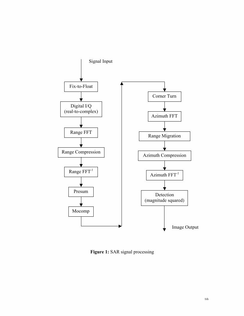
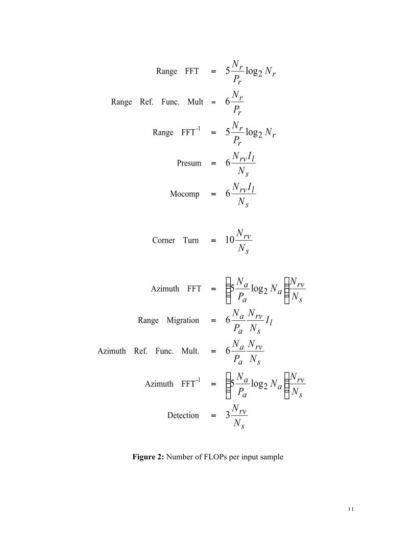
Figure 1 shows the block diagram of the GeoSAR range-Doppler signal processing andFigure 2 gives the numbers of floating-point operations per input sample at eachprocessing stage
10
Corner Turn
Azimuth FFT
Range Migration
Azimuth Compression
Azimuth FFT-1
Detection(magnitude squared)
Signal Input
Fix-to-Float
Digital I/Q(real-to-complex)
Range FFT
Range Compression
Range FFT-1
Presum
Mocomp
Image Output
Figure 1: SAR signal processing
11
s
rv
s
rva
a
a
s
rv
a
a
ls
rv
a
a
s
rva
a
a
s
rv
s
lrv
s
lrv
rr
r
r
r
rr
r
N
N
N
NN
P
N
N
N
P
N
IN
N
P
N
N
NN
P
N
N
N
N
IN
N
IN
NP
N
P
N
NP
N
3
log5
6
6
log5
10
6
6
log5
6
log5
Detection
2FFTAzimuth
Mult.Func.Ref.Azimuth
MigrationRange
2FFTAzimuth
TurnCorner
Mocomp
Presum
2FFTRange
MultFunc.Ref.Range
2FFTRange
1-
1-
=
˜̃¯
ˆÁÁË
Ê=
=
=
˜̃¯
ˆÁÁË
Ê=
=
=
=
=
=
=
Figure 2: Number of FLOPs per input sample

12
1
Ma
1
range samples
Ns
DistributedCorner-Turn
P r
P 2P 1
1
pulse number
Ma
1
Ns
P1
P2
Paz
Range Processing Azimuth Processing
Figure 3: Parallelization of SAR Processing
3. Parallel of SAR Signal Processing
As shown in Figs. 1 and 2, the range-Doppler SAR algorithm can be separated intosequential stages. Hence, the processing can be pipelined to improve the throughput. Inaddition, multiprocessors can be employed in each stage to obtain a further throughputincrease. Fig. 3 shows a possible parallel mechanism for SAR processing.
The range compression can be performed independently of the pulse number. In this firststage of the pipeline chain, multiple processors (P1, P2, … , Pr) can work in parallel toperform the range compression, with each processor responsible for a set of pulse returns.Similarly, the azimuth compression of different range samples can be performedindependently of the range cells. Hence, another set of multiple processors (P1, P2, …,Paz), distributed across the range samples, could be assigned to work in parallel. Betweenthe two compressions in the range and cross-range directions, data needs to be "corner-turned". In this intermediate step, data are transferred from range buffer memory toazimuth buffer memory, and then (matrix) transposed.
13
4. Processing Requirement
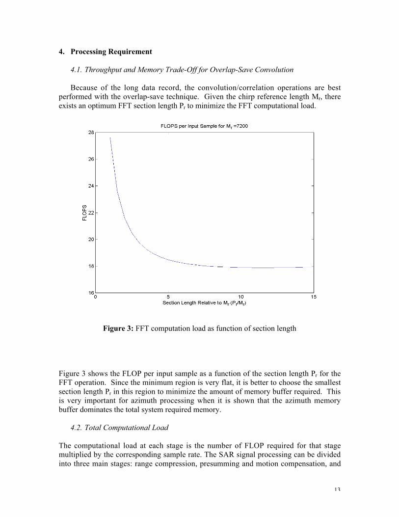
4.1. Throughput and Memory Trade-Off for Overlap-Save Convolution
Because of the long data record, the convolution/correlation operations are bestperformed with the overlap-save technique. Given the chirp reference length Mr, thereexists an optimum FFT section length Pr to minimize the FFT computational load.
Figure 3: FFT computation load as function of section length
Figure 3 shows the FLOP per input sample as a function of the section length Pr for theFFT operation. Since the minimum region is very flat, it is better to choose the smallestsection length Pr in this region to minimize the amount of memory buffer required. Thisis very important for azimuth processing when it is shown that the azimuth memorybuffer dominates the total system required memory.
4.2. Total Computational Load
The computational load at each stage is the number of FLOP required for that stagemultiplied by the corresponding sample rate. The SAR signal processing can be dividedinto three main stages: range compression, presumming and motion compensation, and
14
corner turn and azimuth compression. The sample rate during the range compression stepis given by
After pulse compression, there are only Nrv good samples. Hence, the sample rate for thesubsequent computations is
The computational loads for the three stages are
We recall from Tabs. 1 and 2 that, except for Pr which is the software parameter all theremaining parameters in the above equations are actual radar parameters, fixed at theradar system design level. As discussed in the previous section, Pr is the parameter thatcontrols the trade-off between throughput and memory requirements. Since the lengthsof the range and azimuth reference functions are long for GeoSAR system (in the order of8K to 16K), a 50% overlap in the overlap-save convolution operation (corresponding toPr = Mr and Pa = Ma) is chosen to minimize the amount of memory required.
The number of samples per pulse Ns and the radar PRF fp are inversely proportional to therange resolution dxr and the azimuth resolution dxa, respectively
where gr and ga are the range and azimuth oversampling factors, respectively. Hence, theprocessing load, in general, increases inversely with the square of the image resolution.
aa
aadap
rrrswins
xV
gLV
gBgf
xR
gBcR
gfTN
d
d
===
D=
D==
2
2
prvrv fNQ =
˙˚
˘ÍÎ
È+++=
=
+=
13)66log10(
12
)6log10(
2
2
laa
a
s
rvrvaz
ls
rvrvmc
rr
rrr
INP
N
N
NQC
IN
NQC
NP
NQC
psr fNQ =

15
4.3. Memory Requirements
Each range compression processing element (PE) requires both an input and outputdouble buffer, each of length 2Ns complex samples. If there are Pr range processors, thenthe total range memory required is 4PrNs complex samples. Azimuth processing requiresa corner-turning double buffer in addition to the output image buffer for a total of(2+1)NrvMa = 3 NrvMa. Since the azimuth reference length Ma is on the order of 1,000(X-band) to 20,000 (P-band), and the number of range processors is much smaller (in theorder of 10 to 100), the total memory requirement are dominated by the azimuthprocessing. Assuming 8 bytes per complex sample, the total memory required is
Since
the total memory required is inversely proportional to the cube of the resolution.
5. Mapping SAR Signal Processing into a COTS-Based Parallel Computer: AnExample with GeoSAR using Mercury's SHARC DSP Daughter Cards
Mapping a signal processing application into a COTS-based computer consists ofdetermining the total throughput (GFLOPS), the number of processors, the amount ofmemory (MB), and inter-processor data communication bandwidth (MB).
6.1. Total Throughput and Number of Processors Required
For the GeoSAR radar and processor parameters given in Figures 1 and 2, thethroughputs measured in GFLOPS (number of giga floating-point operations per second)are shown in Table 3
RangeCompression
Presum/Mocomp
AzimuthCompression
TotalThroughput
X-band 1.8 0.25 0.86 2.91P-band 1.8 0.25 1.07 3.12
Table 3: GeoSAR signal processing throughput
( ) arvarvrs MNMNPNM 24348 ª+=
aapa
rrsrv
xVLR
fM
xMNN
dl
d
1
1
µ=
µ-=

16
The total throughput gives only an estimate of the total computations required forthe application. However, not all FLOPS are created equal. This means that a givenprocessor performs some operations faster than other operations. For example, Table 4shows the throughput of a DSP board consisting of Analog Devices' SHARC chips, forthe operations relevant to SAR signal processing 28
Operation Throughput (MFLOPS)Magnitude Squared 26Complex Multiplication 27FIR Filter 45Fixed-to-Float / Float-to-Fixed 80Corner Turn 80Fast Convolution 94
Table 4: Equivalent FLOPS for SHARC-based DSP
To determine the number of PEs required, we need to1. determine the equivalent throughput of the selected PE type (SHARC,
TMS320Cx, PowerPC, i860, …) for each operation, i.e. the processor'sbenchmark.
2. determine the FLOPs required for each operation in the pipelined processing.3. divide step 2. by step 1. to get the number of PE required for each operation.4. add the results of step 3. to get the total number of PE required.
Tables 5 and 6 show the procedure highlighted above for the GeoSAR X-band and P-band radars, respectively. The main difference between the two systems, for processingpurposes, lies in the different azimuth reference lengths due to different radar centerfrequencies. A processing margin of 30% has been assumed for other unaccountedcalculations. We note from these two tables that the range compression requires moreprocessing elements than the azimuth compression, which also includes the corner-turnoperation.
6.2. Memory Requirement
The memory requirements for the range and azimuth processors are shown in Table 7.The required memory for range compression is quite modest compared to the azimuthcompression. A 50% saving in azimuth memory can be obtained if one stores the rangecompressed data in a fixed-point format at the expenses of dynamic range29 andthroughput, since data needs to be converted back to floating-point format after corner-turned for subsequent azimuth processing.
6.3. I/O Bandwidth Requirement
Assuming 8 bytes per complex sample, the total I/O bandwidth rate in the pipeline chain(range compression, corner turn, and azimuth compression) is just 8Q. The I/O

17
Operations FLOPS required(GFLOPS)
SHARC throughput(MFLOPS)
Number ofPEs
Range ProcessingFast Convolution 1.8 94 19.15Presum+Mocomp 0.24 27 8.99Add 2.04 28.14+ 30% overhead 8.44Total PEr required 37
Azimuth ProcessingCorner Turn 0.025 80 0.32Range Migration 0.24 27 8.99Fast Convolution 0.59 94 6.24Magnitude 0.008 26 0.29Add 0.86 15.84+ 30 % overhead 4.75Total PEaz required 21
Table 5: Number of processing elements (PEs) for X-band GeoSAR
Operations FLOPS required(GFLOPS)
SHARC throughput(MFLOPS)
Number ofPEs
Range ProcessingFast Convolution 1.8 94 19.15Presum+Mocomp 0.24 27 8.99Add 2.04 28.14+ 30% overhead 8.44Total PEr required 37
Azimuth ProcessingCorner Turn 0.025 80 0.32Range Migration 0.24 27 8.99Fast Convolution 0.79 94 8.39Magnitude 0.008 26 0.29Add 0.86 17.99+ 30 % overhead 5.40Total PEaz required 24
Table 6: Number of processing elements (PEs) for P-band GeoSAR
18
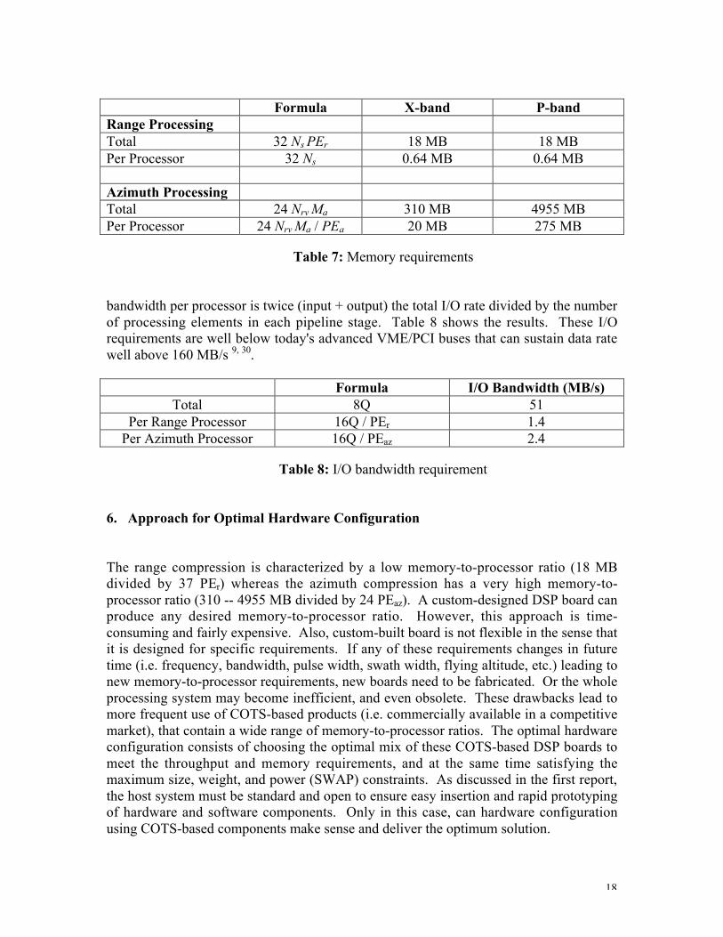
Formula X-band P-bandRange ProcessingTotal 32 Ns PEr 18 MB 18 MBPer Processor 32 Ns 0.64 MB 0.64 MB
Azimuth ProcessingTotal 24 Nrv Ma 310 MB 4955 MBPer Processor 24 Nrv Ma / PEa 20 MB 275 MB
Table 7: Memory requirements
bandwidth per processor is twice (input + output) the total I/O rate divided by the numberof processing elements in each pipeline stage. Table 8 shows the results. These I/Orequirements are well below today's advanced VME/PCI buses that can sustain data ratewell above 160 MB/s 9, 30.
Formula I/O Bandwidth (MB/s)Total 8Q 51
Per Range Processor 16Q / PEr 1.4Per Azimuth Processor 16Q / PEaz 2.4
Table 8: I/O bandwidth requirement
6. Approach for Optimal Hardware Configuration
The range compression is characterized by a low memory-to-processor ratio (18 MBdivided by 37 PEr) whereas the azimuth compression has a very high memory-to-processor ratio (310 -- 4955 MB divided by 24 PEaz). A custom-designed DSP board canproduce any desired memory-to-processor ratio. However, this approach is time-consuming and fairly expensive. Also, custom-built board is not flexible in the sense thatit is designed for specific requirements. If any of these requirements changes in futuretime (i.e. frequency, bandwidth, pulse width, swath width, flying altitude, etc.) leading tonew memory-to-processor requirements, new boards need to be fabricated. Or the wholeprocessing system may become inefficient, and even obsolete. These drawbacks lead tomore frequent use of COTS-based products (i.e. commercially available in a competitivemarket), that contain a wide range of memory-to-processor ratios. The optimal hardwareconfiguration consists of choosing the optimal mix of these COTS-based DSP boards tomeet the throughput and memory requirements, and at the same time satisfying themaximum size, weight, and power (SWAP) constraints. As discussed in the first report,the host system must be standard and open to ensure easy insertion and rapid prototypingof hardware and software components. Only in this case, can hardware configurationusing COTS-based components make sense and deliver the optimum solution.
19
6.1. Choice of Objective Function
In airborne and spaceborn missions, all SWAP constraints are important. Forcomputation processing purposes, the power requirement is the most importantparameter. The weight of a computer system is determined by the custom-built chassis.The size of the system depends on the processing density of the processing elements andon the geometry by which they are arranged. However, power consumption is by far thefundamental variable to be minimized.
6.2. Mercury's COTS -Based Daughter Cards
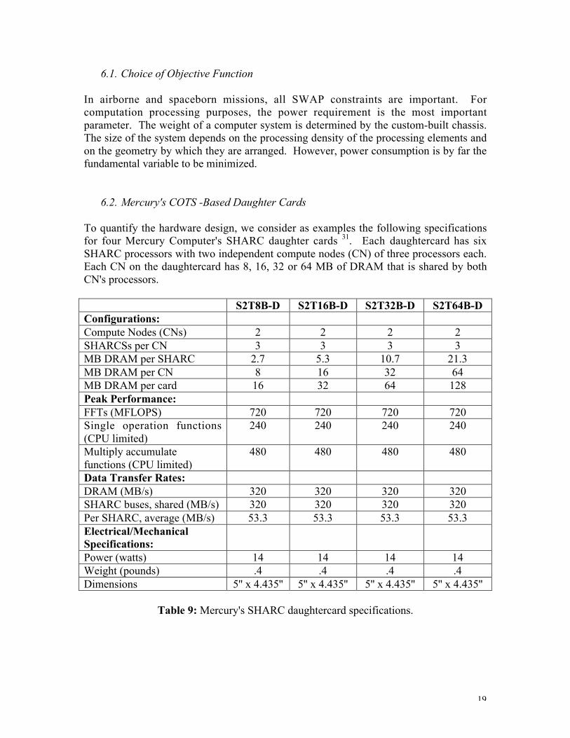
To quantify the hardware design, we consider as examples the following specificationsfor four Mercury Computer's SHARC daughter cards 31. Each daughtercard has sixSHARC processors with two independent compute nodes (CN) of three processors each.Each CN on the daughtercard has 8, 16, 32 or 64 MB of DRAM that is shared by bothCN's processors.
S2T8B-D S2T16B-D S2T32B-D S2T64B-DConfigurations:Compute Nodes (CNs) 2 2 2 2SHARCSs per CN 3 3 3 3MB DRAM per SHARC 2.7 5.3 10.7 21.3MB DRAM per CN 8 16 32 64MB DRAM per card 16 32 64 128Peak Performance:FFTs (MFLOPS) 720 720 720 720Single operation functions(CPU limited)
240 240 240 240
Multiply accumulatefunctions (CPU limited)
480 480 480 480
Data Transfer Rates:DRAM (MB/s) 320 320 320 320SHARC buses, shared (MB/s) 320 320 320 320Per SHARC, average (MB/s) 53.3 53.3 53.3 53.3Electrical/MechanicalSpecifications:Power (watts) 14 14 14 14Weight (pounds) .4 .4 .4 .4Dimensions 5'' x 4.435'' 5'' x 4.435'' 5'' x 4.435'' 5'' x 4.435''
Table 9: Mercury's SHARC daughtercard specifications.
20
6.3. Choices of Hardware Configuration
There are three possible hardware configurations. In the first choice, only one type ofdaughtercards is chosen so that the available processors and memory are shared by bothrange and azimuth processing. From Tables 5 and 6, the number of range processors isabout twice that of azimuth processors. Since each CN has three SHARCs, one SHARCcan be assigned to the range processing while the remaining two perform the azimuthprocessing. For the X-band system, the 64 MB of memory on the S2T64B-D (21.3 MBper SHARC) satisfy the total memory required for these three range and azimuthprocessors. However, none of these cards meets the very high memory-to-processorrequirement (85 MB per processor) for the P-band radar. In this case, some remotememory access is required, thus raising the throughput and power consumption.
Since the memory-to-processor requirements are different for the range andazimuth processors, it is possible to assign two different card types to each of the rangeand azimuth processing. The range (or azimuth) processing will have all the availableSHARC processors (3) and memory on each CN for its own use.
Lastly, in situation where there is a large disproportion between the numbers ofrange and azimuth processors, we can combine the two previous approaches. The firstset of CNs is shared between the range and azimuth processing. The remaining set isexclusively devoted to the processing stage that requires more processors.
The last step is to find the total power consumption as a function of the type andnumber of daughtercards used in the configuration. This power consumption is also afunction of any software parameter in the SAR signal processing (for example, the FFTsection lengths). The objective is to minimize this power consumption subject to thenumber of processors and memory required.
In summary, the time-consuming and expensive problem of custom-designed board isreduced to simple optimization calculation. The availability of different DSP boards in acompetitive market leads to great system flexibility. Use of COTS-based componentswould ensure that these objectives could be met successfully.
7. Summary
In this second we have shown the steps in designing a COTS-based parallel computer forreal-time SAR signal processing. Using the NASA/JPL-developed GeoSAR system as anexample and the Mercury Computer System's SHARC daughtercards as a typicalhardware platform, we have provided the calculations of the resource requirements(number of processors and memory), and different choices of hardware configuration forminimum power.
21
Part III: Parallel Programming Issues
1. Introduction
Parallel programming is the topic in this third and final part. First, we give anoverview of the standard multicomputing platforms and parallel programming models.Then, we compare and contrast "scientific" versus "real-time" processing/programming.Next, we show the hardware/software co-design approach for SAR signal processing.Then, we discuss the current issues in parallel programming. Finally, we describe atypical software architecture for parallel programming of SAR signal processing.
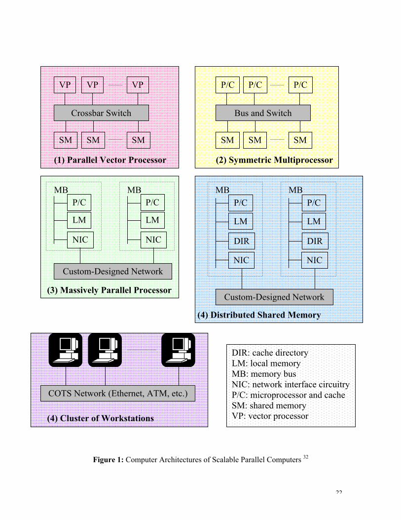
2. Review of Standard Multicomputing Platforms
Scalable parallel computer systems are classified into five general models 32 as shown inFigure 1: the parallel vector processors (PVPs), the symmetric multiprocessors (SMPs),the massively parallel processors (MPPs), the distributed shared-memorymultiprocessors (DSMs), and the cluster of workstations (COWs). The importantcharacteristics of these systems consist of:• Commodity components: using commercial-off-the-shelf (COTS) microprocessors,
memory, disks, and software.• Multiple-instruction-multiple-data (MIMD) architecture: the application program is
divided into processes, each running a possibly different subprogram on differentprocessor.
• Asynchrony: each process executes at its own pace. Synchronization is maintainedthrough the use of semaphores, barriers, sockets, threads, blocking-modecommunications, etc.
• Distributed memory: memory is physically distributed among different computenodes (CNS), either shared or unshared. Memory access is carried out using uniform-memory-access (UMA) or non-uniform-memory-access (NUMA) models. Becauseof its centralized shared memory, the UMA model may limit scalability once built.
Table 1 compares the architectural attributes and performance of these five parallelarchitectures.
22
Crossbar Switch
VP VP VP
SM SM SM
(1) Parallel Vector Processor
Bus and Switch
P/C P/C P/C
SM SM SM
(2) Symmetric Multiprocessor
Custom-Designed Network
NIC
LM
P/CMB
NIC
LM
P/CMB
(3) Massively Parallel ProcessorCustom-Designed Network
DIR
LM
P/CMB
DIR
LM
P/CMB
(4) Distributed Shared MemoryMachine
NIC NIC
COTS Network (Ethernet, ATM, etc.)
(4) Cluster of Workstations
DIR: cache directoryLM: local memoryMB: memory busNIC: network interface circuitryP/C: microprocessor and cacheSM: shared memoryVP: vector processor
Figure 1: Computer Architectures of Scalable Parallel Computers 32
23
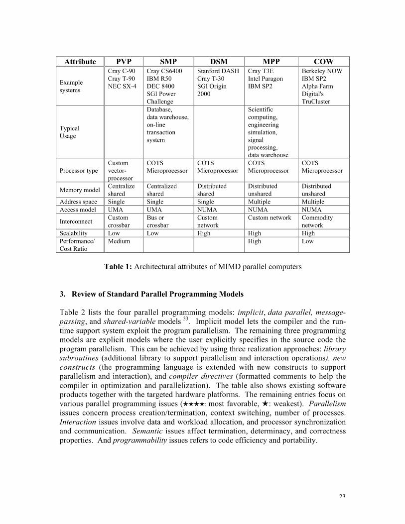
Attribute PVP SMP DSM MPP COW
Examplesystems
Cray C-90Cray T-90NEC SX-4
Cray CS6400IBM R50DEC 8400SGI PowerChallenge
Stanford DASHCray T-30SGI Origin2000
Cray T3EIntel ParagonIBM SP2
Berkeley NOWIBM SP2Alpha FarmDigital'sTruCluster
TypicalUsage
Database,data warehouse,on-linetransactionsystem
Scientificcomputing,engineeringsimulation,signalprocessing,data warehouse
Processor typeCustomvector-processor
COTSMicroprocessor
COTSMicroprocessor
COTSMicroprocessor
COTSMicroprocessor
Memory modelCentralizeshared
Centralizedshared
Distributedshared
Distributedunshared
Distributedunshared
Address space Single Single Single Multiple MultipleAccess model UMA UMA NUMA NUMA NUMA
InterconnectCustomcrossbar
Bus orcrossbar
Customnetwork
Custom network Commoditynetwork
Scalability Low Low High High HighPerformance/Cost Ratio
Medium High Low
Table 1: Architectural attributes of MIMD parallel computers
3. Review of Standard Parallel Programming Models
Table 2 lists the four parallel programming models: implicit, data parallel, message-passing, and shared-variable models 33. Implicit model lets the compiler and the run-time support system exploit the program parallelism. The remaining three programmingmodels are explicit models where the user explicitly specifies in the source code theprogram parallelism. This can be achieved by using three realization approaches: librarysubroutines (additional library to support parallelism and interaction operations), newconstructs (the programming language is extended with new constructs to supportparallelism and interaction), and compiler directives (formatted comments to help thecompiler in optimization and parallelization). The table also shows existing softwareproducts together with the targeted hardware platforms. The remaining entries focus onvarious parallel programming issues (HHHH: most favorable, H: weakest). Parallelismissues concern process creation/termination, context switching, number of processes.Interaction issues involve data and workload allocation, and processor synchronizationand communication. Semantic issues affect termination, determinacy, and correctnessproperties. And programmability issues refers to code efficiency and portability.

24
Issues Implicit Data Parallel Message Passing Shared Variable
Platform Independent Examples
Kap,Forge
Fortran 90/95Fortran 2001HPF, HPF-2PC++, Nesl
PVM,MPI, MPI-2
X3H5POSIX ThreadsOpenMPC//
Platform Dependent ExamplesConvexExemplar
CM C* IBM SP2,Intel Paragon
Cray MPP,SGI Power C
Parallel Hardware PlatformsPVP, SMP,MPP, DSM,COW
MPP, COW PVP, SMP,MPP, DSM,COW
Realization ApproachNewconstruct,directives
Library Library
Parallelism issues HHHH HHH HH HH
Data Allocation HHHH HH H HHHComputationAllocation
HHHH HHHH HH HHH
Communication HHHH HHH H HHHInteraction Issues
Synchronization HHHH HHHH HH HTermination HHHH HHHH H HDeterminacy HHHH HHHH HH HSemantic IssuesCorrectness HHHH HHH H HEfficiency H HH HHHH HHHHProgrammability
Issues Portability HHHH HHH HHH H
Table 2: Comparison of four parallel programming models 33.
Table 3 further classifies the explicit programming models based on their architecturesand working principles. Further information can be found in the references 32, 33.
Feature Data Parallel Message Passing Shared VariableControl Flow(threading)
Single Multiple Multiple
SynchronyLooselysynchronous
Asynchronous Asynchronous
Address Space Single Multiple MultipleInteraction Implicit Explicit Explicit
Data AllocationImplicit orSemi-explicit Explicit
Implicit orSemi-explicit
Table 3: Main features of explicit parallel programming models 33.
4. Comparison between "Scientific" and Real-Time" Computing
Traditional supercomputers (PVP, SMP, MPP) with general-purpose computing designphilosophy have served well the scientific and business computing markets 34, 35. Incontrast, embedded systems are often found in real-time, sensor-based, signal and imageprocessing applications. The fundamental characteristics separating the two applications

25
are: application flow, deterministic requirements, support for heterogeneity, and hardwareutilization requirements 34.
In scientific applications data are given just once as an initial value problem andevolve according to a scientific model. Each evolution step involves different andcomplicate operations and is subjective to change with respect to the previous steps,depending on the data runtime value.
In real-time, sensor-based applications, the execution process is divided into twophases: SETUP and GO phases. During the SETUP phase, the software performsfunctions with high level of latency and low level of determinism, such as sharedmemory creation, processors hiring, task partitioning and scheduling, initialization ofparallel libraries, and establishing of processor communication/synchronization. Thanksto the regularity of the processing during the GO phase, this SETUP procedure isperformed only once and the entire subsequent processing can be completely plannedahead. That is, the processing regularity permits static task mapping and scheduling (i.e.task mapping and scheduling are determined at compile time). This is in contrast toscientific programming where dynamic task profiling and scheduling are required.
The software then gives way in the GO phase where the hardware takes over andmanages the data movement and transformation. During this time, the sensorcontinuously delivers data, probably at a high rate, to be processed. However, theprocessing is relatively simple (FFT, filtering, etc.), repetitive, and predictable. That is,data value do not dictate what the application should do, as with scientific applicationthat decides which conditional branch to process based on data values in the previoussteps. Thus real-time sensor-based applications require quick and deterministicperformance. What separate real-time programming from scientific programming arehigh data refreshing rate, its passive nature, and the processing regularity.
As mentioned previously, real-time applications require uninterrupted data collectionand continuously concurrent processing of data. These requirements lead to high demandfor deterministic control, high-speed processing, and efficient communication andsynchronization mechanism. In addition, real-time embedded systems require extremelyhigh hardware utilization (optimal use of resource) in terms of performance (MFLOPS)per cubic foot, per pound, per watt, and per dollar. This implies maximal hardware finetuning and minimal software overhead. Thus, both hardware and software latencies mustnot only be low, but also deterministic in order to keep up with the continuous datastream.
To meet the high hardware utilization, embedded real-time applications are bestserved by a heterogeneous mix of processors 36. For example, custom processors can beused for low latency I/O interfaces and FFT calculations. DSP chips are ideal for vectortasks, such as digital filtering, image formation, data reconstruction and resampling, andsignal classification. And RISC can be employed to perform scalar task, such as featureextraction, inverse problem, parameter retrieval, image classification and interpretation,

26
large scale (global) surveying and understanding, target detection, and decision makingprocesses.
In general, there are three types of heterogeneous computing (HC) models: mixed-machine model, mixed-mode model, and mixed-component model 37. In a mixed-machine system, a heterogeneous mix of independent machines of different types areinterconnected by a high-speed network (e.g. crossbar switch, SCI, HiPPI, Myrinet, fiberchannel, gigabit Ethernet, etc. 33). A mixed-mode system has a single parallel machinewhose processors are capable of operating in either the synchronous SIMD orasynchronous MIMD mode, and can dynamically switch between these two modes. Amixed-component system consists of a machine with different components where eachrepresents one mode of parallelism.
5. Heterogeneous Multicomputing for SAR Real-time Processing
SAR signal processing (filtering, image formation, detection, classification, etc.) usuallyinvolves different types of computation (vector and scalar processing) 2. Consequentlythe corresponding signal processing architecture is best served with a mix of computingtechnologies 36, 38. Homogeneous machines, where only one type of microprocessor isemployed, cannot achieve their peak performance during the entire process. This is duethe fact that different algorithms within the SAR signal processing have differentcomputational requirements. And currently there is no single microprocessor architecturethat can serve all computational requirements equally well 36. To meet the highthroughput and low latency requirements, real-time SAR signal processing calls forheterogeneous platform where each processor is tailored to match with the type ofcomputation for which it was designed 38, 39, 40, 41.
Figure 2 shows the software domain (computational model) and hardware domain(hardware realization) for real-time SAR signal processing using a heterogeneousmulticomputing platform. The actual parallel implementation is a parallel pipelinedsystem where each pipeline is a collection of tasks and each task itself is parallelized.This helps in improving throughput and latency, whose definition and discussion will begiven in the subsequent sections.
In the first stage, the sensors deliver analog data to be digitized by the I/O device (e.g.A/D converter). The digital data are then compressed (filtered, convolved, etc.) to formimage. While this stage is highly computationally intensive, the processing can beseparated (pipelined) into well-defined vector subtasks (range compression, cornerturning, azimuth compression, etc.) where multiple processors can be employed inparallel. Also, these filtering operations are very regular, repetitive, and requireminimum software conditional branches. Hence, DSP chips are best suited for thissecond stage. The third stage consists of image segmentation and feature extraction.This stage is characterized by mixed vector and scalar operations, which can beeffectively performed with multiple microprocessor units running in parallel. The nextstage involves data interpretation and decision making. The processing is highly scalar in

27
Sensor FilteringSegmentExtract Display
Detection Decision
High-Speed Buses or Switches
SHARCsTMS320x
i860PowerPC PowerPC
A. ProgrammingA. Programming
ModelModel
C. HardwareC. Hardware
ModelModel
Pulsecompression
AzimuthcompressionCorner-turn
B. B. Parallelizing and Parallelizing and Pipelining thePipelining the
Filtering StageFiltering Stage
Figure 2: SAR signal processing on heterogeneous multicomputing platform.
nature, requiring complex software programming, and utilizing mostly conditionals, tablelook-ups, jumps, for which RISC processors present better fits than DSP chips. Finally,the processed data are stored on high-speed tapes or sent out to a display device. An I/Odevice is responsible for this bulk data movement.
6. Parallel Programming Issues
As described in the first two parts 1, 2, COTS components offer many advantages interms of system scalability, programmability, flexibility, performance with respect to

28
size, weight, power, and cost. However, COTS components are not originally designedto guarantee optimal performance for a particular application. Hardware integrationalone is not sufficient to meet the performance requirements.
To fully exploit the use of a heterogeneous mix of COTS components, softwareprogramming tools such as high-level language, efficient parallel library, task profilingand analytical benchmarking, task mapping and scheduling, supporting compiler andoperating system mechanisms, should be available to the programmers. Currently,parallel programming technique is not advanced enough to permit automation of taskmapping and scheduling 33, 37. The user must explicitly decompose the application intoappropriate subtasks, decide on which machine to execute each subtask, code eachsubtask specifically for its targeted machine, and determine the relative executionschedule for the subtasks. However, full automation is an active research topic both inacademia and industry.
7.1. Communication time
In an integrated system which implements several tasks that feed data to each other,each tasks takes some amount of time that equals to the sum of 42
• Time required to transfer the input data from the previous task.• Time required to process the data.• Time required transfer the output data to the next task.
Therefore, in addition to the processing time, communication time (between theprocessing units, between the processing unit and its on-chip memory, between theprocessing unit and the bulk memory storage) is also needed among the tasks.Experience over the years has shown that processor speed is increasing at a faster ratethan the speed increase of memory and interconnect network 33 . In fact, communicationtime is the major overhead that can adversely impact scalability when mapping anembedded signal processing application onto a high-performance computing platform 39.
There are two types of data dependencies that can affect the communication time:spatial and temporal data dependency. Spatial data dependency is classified into intra-task and inter-task dependencies. Intra-task dependency occurs when subtasks areexchanging intermediate results (i.e. overlap-add and overlap-save convolution). Inter-task dependency results from data movement between parallel tasks (i.e. pulsecompression followed by azimuth compression). Temporal dependency arises whenprevious data set is needed for the current process. Good understanding of the data flowand efficient data re-distribution and task scheduling is required in order to meet theperformance requirement.
7.2. Throughput and Latency
While other parameters such as size, weight, power, and cost impose constraints onthe hardware/software architecture, two of the most important parameters that need to be

29
optimized are throughput and latency 39, 43. Throughput is the average rate at whichoutput sample leaves the system. The system throughput must keep pace with the inputdata rate. Latency is the worst-case time between the transform of an input sample andthe delivery of the processed output sample. The system latency is such that all theprocessing must be done within an assigned time. The throughput/latency optimizationproblem consists of minimizing the number of processors needed to satisfy thethroughput requirement subject to the latency constraint. Numerous research studieshave been conducted and several models have been proposed to help minimize latencyand maximize throughput, for a given number of processors 37, 39, 43.
7. Typical Software Architecture for SAR Real-Time Signal Processing
In this section, we provide an example of a typical parallel software structure. Theexample shown below represents the architecture designed for Mercury's RACEwaymulticomputer 42. The process breaks down into SETUP code and GO code
SETUP Phase• Allocate local memory• Boot compute elements• Spawn processes• Create endpoints• Create transfer requests• Set up synchronization objects• Set up look-up tables
GO Phase (inner-loop functions)while (is_data_coming?)
• Get data in• Process data• Send data out
end while
The descriptions of the activities are given below.
7.1. SETUP Code
• Allocating local memory: to allocate memory for function calls, to provide alignedmemory for special library calls, and to allocate on-chip memory on certain DSPchips (such as the SHARCs).
• Booting compute elements (CE): to load an executive into the targeted CE'smemory and to provide the physical address of the targeted CE in a interprocesscommunication database.
• Spawning processes: to load an executable image into the targeted CE's memory.

30
• Creating endpoints: to create endpoints which include shared memory buffer (SMB,associated with random-access memory) and stream endpoints (associated withdevices).
• Creating transfer requests: to define the source endpoint, the transfer engine, andthe destination endpoint for a particular transfer. Endpoints can be SMB or devices.Transfer engine include direct memory access controller (DMA engine) and the DMAengine for external devices.
• Setting up synchronization objects: Standard synchronization objects include:sockets, semaphores, and signals. Sockets provide full-duplex message passingbetween processes. Semaphores are used for synchronization. And signals provideasynchronous notification to processes.
• Setting up look-up tables: to create look-up tables for frequent used functions andtransforms such as trigonometric functions and fast Fourier or discrete cosinetranforms.
7.2. GO Codes (inner-loop processing)
• Data transfer: data movement extensively used transfer requests previously createdin the SETUP phase. Data transfer can be between processes, between a process anda logical device, and between a process and a raw device.
• Processing data: inner-loop processing is usually performed with parallel libraryfunctions that have been optimized for a targeted processor. Input data should residein local memory to reduce the communication time from reading external memory.
8. Summary
In this final part, we reviewed the standard multicomputing platforms and parallelprogramming techniques. We then compared scientific programming and real-timesensor-based processing where a heterogeneous system offers many advantages. We alsopointed out that parallel programming is not a mature technique and presents manychallenges. The ultimate goal is to provide full automation of the hardware/software co-design. Until this automatic tool is available, the hardware designer and softwareprogrammer must explicitly specify the task partitioning and handle all the softwarecommunication/synchronization processes to ensure low latency and high throughput tomeet performance specifications.

31
REFERENCES: 1 C. Le and S. Hensley, "Using COTS components for real-time processing of SARsystems", First Report, Jet Propulsion Laboratory, Pasadena, CA, July 1998.
2 C. Le and S. Hensley, "Using COTS components for real-time processing of SARsystems", Second Report, Jet Propulsion Laboratory, Pasadena, CA, August 1998.
3 C. Le and S. Hensley, "Using COTS components for real-time processing of SARsystems", Third Report, Jet Propulsion Laboratory, Pasadena, CA, September 1998.
4 R. Jaenicke, "Multiprocessing issues in large systems", Computer Design, pp. 51-53,December 1996.
5 K. Hwang, Advance Computer Architecture: Parallelism, Scalability, Programmability,McGraw-Hill, Inc., New York, NY, 1993.
6 J. Child, "PCI, VME boards vie for image processing designs", Computer Design, pp.91-97, April 1998.
7 L. Happ, F. Le, M. Ressler, and K. Kappra, " Low-frequency ultra-wideband syntheticaperture radar: Frequency subbanding for targets obscured by the ground", in RadarSensor Technology, G. S. Ustach, Editor, Proc. SPIE, vol. 2747, pp. 194-201, 1996.
8 R. Dressler, D. Barnum, and M. Loiz, "COTS SAR processing software", IEEENational Radar Conference, pp. 136-141, 1996.
9 S. Ohr, "New-generation radar processing depends on fast A/D converters:, ComputerDesign, pp. 85-90, August 1996.
10 R. W. Bayma and E. Trujillo, "HISAR COTS-based synthetic aperture radar",Proceedings of the 15th IAA/IEEE Digital Avionics Systems Conference, pp. 319-325,1996.
11 P. G. Meisl, M. R. Ito, and I. G. Cumming, "Parallel processors for synthetic apertureradar imaging", Proceedings of the International Conference on Parallel Processing,1996.
12 TNO Physics and Electronics Laboratory, "RACEway Compatible Pulse CompressionBoard", http://www.tno.nl/instit/fel/div3/pulsbord.html.
13 B. C. Kuszmaul, "The RACE network architecture", Proceedings of the 9th
International Parallel Processing Symposium (IPPS'95), pp. 508-513, April 1995.
14 T. H. Einstein, "Mercury Computer Systems' modular heterogeneous RACEmulticomputer", Proceedings of the 6th Heterogeneous Computing Workshop (HCW '97),April 1997.

32
15 J. M. Rabaey, W. Gass, R. Broderson, T. Nishitani, and T. Chen, "VLSI design andimplementation fuels the signal-processing revolution", IEEE Signal ProcessingMagazine, vol. 15, no. 1, pp. 22-37, January 1998.
16 3L Limited, "Parallel C and Multiprocessor DSP RTOS Software Solutions".
17 J. Gadient, and G. A. Frank, Editors, Rapid Prototyping of Application Specific SignalProcessors, M. A. Richards, A., Kluwer Academic Publishers, January 1997.
18 K. Konstantinides, "VLIW architectures for media processing", IEEE SignalProcessing Magazine, vol. 15, no. 2, pp. 16-19, January 1998.
19 P. Faraboschi, G. Desoli, and J. A. Fisher, "The latest word in digital and mediaprocessing", ", IEEE Signal Processing Magazine, vol. 15, no. 2, pp. 59-85, January1998.
20 Van Zyl et. al., "GeoSAR P-band radar CDR", Jet Propulsion Laboratory, Pasadena,CA, May 1997.
21 S. Hensley et. al., "GeoSAR IFSAR processor PDR/CDR", Jet Propulsion Laboratory,Pasadena, CA, September 1997.
22 Van Zyl et. al., "GeoSAR X-band radar CDR", Jet Propulsion Laboratory, Pasadena,CA, November 1997.
23 J.C. Curlander and R.N. McDonough, Synthetic Aperture Radar: Systems and SignalProcessing, Wiley, 1991.
24 W. Owens, "Why COTS is vital to the modern military?", COTS' 95 Conference, 1995
25 R. Costello, "Commercial Products and Military Preparedness", COTS' 95 Conference,1995.
26 D. MacDonald, J. Isenman, and J. Roman, "Radar detection of hidden targets",NAECON 1997 Proceedings of the IEEE 1997 National Aerospace and ElectronicsConference, pp. 846-855, 1997.
27 R. W. Bayma and E. Trujillo, "HISAR COTS-based synthetic aperture radar",Proceedings of the 15th IAA/IEEE Digital Avionics Systems Conference, pp. 319-325,1996.
28 T. Einstein, "Realtime synthetic aperture radar processing on the RACEMulticomputer", Application Note 203.0, Mercury Computer Systems Inc., 1995.
29 P. Lapsley, J. Bier, A. Shoham, and E.A. Lee, DSP Processor Fundamentals:Architectures and Features, IEEE Press, 1997.

33
30 J. Child, "PCI, VME boards vie for image processing designs", Computer Design, pp.91-97, April 1998.
31 Race Series SHARC Daughtercards, Mercury Computer Systems Inc., 1998.
32 K. Hwang and Z. Xu, "Scalable parallel computers for real-time signal processing",IEEE Signal Processing Magazine, pp. 50-66, July 1996.
33 K. Hwang and Z. Xu, Scalable Parallel Computing: Technology, Architecture, andProgramming, McGraw-Hill, 1998.
34 "Embedded applications for high performance computing", Panel Session, URL:http://www.mc.com/backgrounder_folder/embedded_panel/panel.html
35 "Fitting architecture to application: Choosing between SMP and RACE",Multicomputing Technology Brief, 1996.
36 R.F. Freud and H.J. Siegel, "Heterogeneous processing", IEEE Computer, vol. 26, no.6, pp. 13-17, 1993.
37 H.J. Siegel, H.G. Dietz, and J.K. Antonio, "Software Support for HeterogeneousComputing", in The Computer Science and Engineering Handbook, Allen B. Tucker, Jr.editor, CRC Press, Inc., 1997.
38 H.J. Siegel, J.K. Antonio, R.C. Metzger, M. Tan, and Y.A. Li, "HeterogeneousComputing", in Parallel and Distributed Computing Handbook, A.Y.H. Zomaya editor,McGraw-Hill 1996.
39 W. Liu and V.K. Prasana, "Utilizing the power of high-performance computing", IEEESignal Processing Magazine, vol. 15, no. 5, pp. 85-100, September 1998.
40 S.C. Patterson, "Heterogeneous multicomputing", EDN Products Edition, July 18,1994
41 B. Isenstein, "VMEbus leads as fast processors stress system interconnect", EE TimesVITA Insert Supplement page, vol. 9, April, 1996.
42 Developer's Guide, Mercury Computer Systems, Inc., 1997.
43 A. Choudhary, W. Liao, D. Weiner, P. Varshney, R. Linderman, and M. Linderman,"Design, implementation, and evaluation of parallel pipelined STAP on parallelcomputers", 1998 IPPS/SPDP, Proceedings of the 12th International Parallel ProcessingSymposium and 9th Symposium on Parallel and Distributed Processing, pp. 220-225,Orlando, Florida, 1998.