Embed Size (px)
Citation preview

2" Cover @
Open Joints
Begin or End Retaining Wall
and Precast or C-I-P Coping
3"
Field cut reinforcing as required
to maintain minimum cover (Typ.)
3 sp.@ 6"
3"
4 ~ Bars 5F
(Top of Slab)
(Required only
when Junction
Slab is skewed)
Bars 5B1 Coping
2" Cover @
Expansion Joints
Gutter Line
Expansion Joint (See
"Expansion Joint Detail"
this sheet and Detail "A")Sides (Typ.)
2" Cover
Ƃ " Open Joint
ƀ" V-Groove Spacing
Ƃ " Open Joint
in Precast Coping
1" Ø Dowel Load
Transfer DevicesTop of
Junction Slab
Approved metal
or fiber cap
1'-0"1'-0"
Bottom of
Junction Slab
1" Ø Dowel Load Transfer
Devices (See Typical Sections
for details)
Ƃ" Preformed Expansion
ƃ"
(Junction Slab expansion joints are to coincide
with Ƃ" open joints in Concrete Barrier)
CROSS REFERENCE: For Detail "A", see Sheet 2.
EXPANSION JOINT DETAIL
Bars 5B2
Bars 5A @
6" (Typ.)
Bars 5B1
2'-
2"
Min.
Lap S
plice
30'-0" Max. (See Note 7)
ƀ" V-Groove (See
Note 7 & Detail "A")
Approach Slab
(See Note 12)
Spacing Bars 4V1
� Ƃ" Open Joint in Precast
Coping and C-I-P Traffic
Railing to coincide with Ƃ"
Expansion Joint in Junction
Slab.
PARTIAL ELEVATION VIEW
(Precast Coping and Junction Slab Reinforcing not Shown for Clarity)
(Precast Coping Shown, C-I-P Coping Similar)* C-I-P End Section must
be ≥ 12'-0".
Bars 5C @ 6" sp.
(Typ.)
Optional
Shear Key
(See Note 5)
1ƀ"4ƀ"
4ƀ"
Min.
� Expansion Joint
Joint Filler**
are permitted to form joints.
** Stay-In-Place Plastic Preformed Bond Breakers
Min.
3"
SINGLE-SLOPE CONCRETE BARRIERS
Ƃ" Expansion Joint Spacing ~ 30'-0" Min. (36" Single-Slope), 60'-0" Min. (42" Single-Slope), 90'-0" Max. (See Note 4)
Bars 5L @ 12" sp.
(Typ.)
3"Spacing Bars 5V1
42" Single-Slope
36" Single-Slope
6" Spacing (Typ.) (See Note 9)
6" Spacing (Typ.) (See Note 9)
Bars 4V1 or
5V1 (Typ.)
Clearance
Varies
2"
Cover
Min.
Varie
s
Bottom of
Precast Coping
Top of Retaining
Wall Panel (Typ.)
Top of Precast Coping
Varie
s
(11"
Max.)
10'-0" Typical Precast Coping Only (5'-0" Min.)
Concrete Barrier
Retaining Wall (MSE Shown,
Other Types Similar) (Typ.)
� Ƃ" Open Joint in
Precast Coping and
Precast Concrete Barrier
Top of
Concrete
Barrier
3"
Mortar Plug
(See Note 4)
12'-0" Minimum Precast Concrete Barrier & Coping Sections *
2'-
5"
Top of C-I-P
Buildup Concrete
Dowels 4D (Typ.)
(See Note 10)
1'-
0"
2'-
3"
Transitio
n
Copin
g
Begin or End
Retaining Wall
and Precast or
C-I-P Coping
Typic
al
Copin
g
2"
Gutter
Line
Varie
s
PARTIAL PLAN VIEW FOR 36" SINGLE-SLOPE CONCRETE BARRIER
(Skewed Approach Slab Shown, Perpendicular Approach Slab Similar)
(Precast Coping Shown, C-I-P Coping Similar) (Concrete Barrier not Shown for Clarity)JUNCTION SLAB NOTES:
1. Construct the expansion joints, V-Grooves and face of coping plumb.
2. Provide Class II concrete for slightly aggressive environments or Class IV for moderate or extremely
aggressive environments.
3. Dowel Load Transfer Devices will be hot-dip galvanized ASTM A 36 smooth round bar, or GFRP smooth
round bars with a minimum shear strength of 22 ksi in accordance with ASTM D7617. Install Dowel Load
Transfer Devices in accordance with Specification Section 350.
4. Construct Ƃ" Expansion Joints in junction slabs and C-I-P copings plumb and perpendicular or radial to the
Gutter Line. Provide at 90'-0" maximum intervals as shown. Provide 3"x3" Mortar plugs in open joints at the
base of Concrete Barriers to contain runoff.
5. Shear Keys in Junction Slab are required when GFRP bars are used for Dowel Transfer Devices and are
horizontal.
6. Provide and install Preformed Expansion Joint Filler in accordance with Specification Section 932.
7. Construct ƀ" V-Grooves in junction slabs and C-I-P copings at 30'-0" maximum intervals as shown.
Space V-Grooves equally between Ƃ" Expansion Joints and/or Begin or End Junction Slab. V-Groove
locations are to coincide with V-Groove locations in the Concrete Barrier.
8. Shoulder or Roadway Pavement is required on top of the junction slab for its entire length on the traffic
side of the Concrete Barrier. See Typical Sections on Sheets 2 and 3 for details.
9. Spacing shown is along the Gutter Line.
10. For Precast Coping only, provide Dowel Bars 4D embedded 1'-0" and extended 9" above the top of MSE wall panels.
Field cut as necessary to maintain 2" minimum cover to the top of the buildup concrete. See Wall Company
Drawings for number and spacing of Dowel Bars 4D.
11. The following Indexes contain details of the intersection of the retaining wall at approach slabs:
Index 400-090 - Approach Slabs (Flexible Pavement Approaches)
Index 400-091 - Approach Slabs (Rigid Pavement Approaches)
10/30/2017
3:0
0:3
3 P
M
RE
VISIO
N DESCRIPTION:
REVISION
LAST
ofSTANDARD PLANS
FY 2018-19 SHEETINDEX CONCRETE BARRIER/JUNCTION SLAB
- WALL COPING
11/01/17 1521-610 3

Coping
Precast Coping
(Showing Locations of ƀ" V-Grooves and Ƃ" Preformed Expansion Joint Filler)
ƀ" V-Groove (Typ.) ƀ" V-Groove (Typ.)
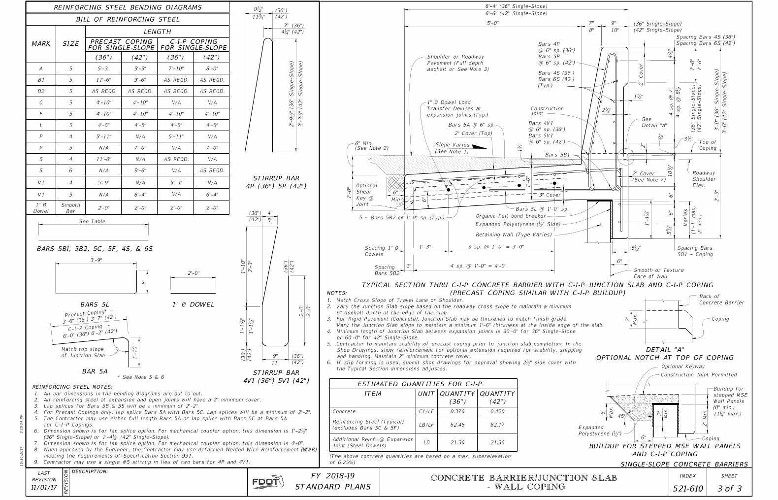
DETAIL "A"
PRECAST COPING
Concrete
Barrier
Ƃ" Preformed ExpansionJoint Filler
Ƃ" Preformed ExpansionJoint Filler
NOTES:
C-I-P COPING
SINGLE-SLOPE CONCRETE BARRIERS
TYPICAL SECTION THRU PRECAST 36" SINGLE-SLOPE
CONCRETE BARRIER AND COPING WITH C-I-P JUNCTION SLAB
Bars 5B1
Bars 5A @ 6" sp.
"4
3
"4
31
1'-
0"
1" Ø Dowel Load
Transfer Devices at
expansion joints (Typ.)
2" Cover (Top)
Spacing Bars 5B1
6"
2" Cover
(See Note 1)
Slope Varies
Shoulder or Roadway
Pavement (Full depth
asphalt or See Note 3)
(C-I-P Junction Slab)
(Precast Copin
g)
Ƃ"
3" CoverBars 5B2 @ 1'-0" sp. (Typ.)
6"
6"
3"
Retaining Wall (Type Varies)
Optional widening & extension for Precast Coping (See Note 6)
"4
11'-
1
Coping
Top of
3 sp. @ 1'-0" = 3'-0"Spacing 1" Ø
Dowels
1'-3"
Spacing
Bars 5B2
Face of Wall
Smooth or Textured
3"
"415
6"
5Ƃ"
2" Min. Cover
Dowel Bars 4D (MSE Walls only)
Utility Conduitpermitted
(MSE Walls only)
C-I-P Buildup Concrete
ƀ" Min. ~ 2ƀ" Max. Gap (See Note 7)
Slope Permitted (See Note 8)
1'-
0"
6ƀ" Min.
(See Note 2)
6"
Min
Optional
Shear
Key @
Joint
Organic Felt bond breaker
Min. Embed.
(36" Single-Slope)
(42" Single-Slope)
2'-
5"
Bars 4V1@ 6" sp.
Bars 4P
@ 6" sp.
3'-
0"
"2
14
Spacing Bars 4S
"212
"211
2"
Cover
9"7"5'-0"
6'-4"
4 sp. @ 1'-0" = 4'-0"
Bars 5C @ 6" sp.
Tied to Bars 5A
4"
1ƀ"
1'-1"
1'-3"
Bars 4V or
5V (Cut &
Field Bent)
Gutter Line
PARTIAL END VIEW OF CONCRETE BARRIER END
TRANSITION FOR GUARDRAIL ATTACHMENT
(Precast Coping Shown, C-I-P Coping Similar)
1. Match Cross Slope of Travel Lane or Shoulder.
2. Vary Junction Slab slope based on roadway cross slope to maintain a minimum 6" asphalt
depth at the edge of the slab as shown.
3. For Rigid Pavement (Concrete), Junction Slab may be thickened to match finished grade.
Vary the Junction Slab slope to maintain a minimum 1'-6" thickness at the edge of the slab.
4. Minimum length of Junction Slab between expansion joints is 30'-0".
5. At the Contractor's option, mechanical couplers may be used to splice reinforcing.
Complete details, including reinforcement lengths are required in the Shop Drawings.
Provide mechanical couplers in accordance with Specification Section 415. Mechanical
couplers shall develop 125% of the bar yield strength.
6. Contractor to maintain stability of precast coping/Concrete Barrier prior to junction slab
completion. In the Shop Drawings, show reinforcement for optional extension required
for stability, shipping and handling. Maintain 2" minimum concrete cover.
7. When the air gap between the precast coping extension and retaining wall exceeds 2ƀ",
fill gap with full depth Expanded Polystyrene to provide a maximum 2ƀ" air gap.
8. Angle varies ~ 0° min., 25° max.
"2
110
2"
ConstructionJoint
Roadway
Shoulder
Elev.
Bars 5L @ 1'-0" sp.
9"
3'-0"
3"
Coping
BA
B
B
DETAIL "A"
A
A
3'-0"
A
B
2'-0"
Connector Bolts
� Thrie-Beam Terminal
Approach Slab maintain cover
Field Bend to
Transition
4"
2'-0"
Connector Bolts
� Thrie-Beam Terminal
"212
(Max.)
Bars P @ 6" sp.
@ 6" sp. (Max.)
End Bars P
Coping
Transition
4"
3"
(2" min.)
Varies
Top of
Precast
Coping
PLAN - RAILING END TRANSITION
(Showing Bars P and S)
Bars 5B1
(Field Bent)
36"
42"
36"
42"
1'-
6"
1'-
4"
3"
36"
42"
1'-
3"
1'-
1"
3"
36"
42"
(Typ.)
Bars P
Bars S (Top)
(Bottom)
Bars S
(Typ.)
Bars V
PLAN - RAILING END TRANSITION
(Showing Bars V and S)
1'-
6"
1'-
4"
1'-
3"
1'-
1"
3"
36" ~ Bars 4V @ 6" sp. (Max.)
42" ~ Bars 5V @ 6" sp. (Max.)
4 sp.
@ 7"
"2
13
1'-4"
See Detail
"A" Sheet 3
12'-
0"
Min.
Length)
(Precast Concrete Barrier
10/30/2017
3:0
0:3
4 P
M
RE
VISIO
N DESCRIPTION:
REVISION
LAST
ofSTANDARD PLANS
FY 2018-19 SHEETINDEX CONCRETE BARRIER/JUNCTION SLAB
- WALL COPING
11/01/17 2 3 521-610
10/30/2017
3:0
0:3
4 P
M
RE
VISIO
N DESCRIPTION:
REVISION
LAST
ofSTANDARD PLANS
FY 2018-19 SHEETINDEX
3"
2'-0"
2'-0"2'-0"
5
5
5F
C
A
BAR 5A
1" Ø DOWEL
REINFORCING STEEL BENDING DIAGRAMS
3'-9"
8"
BARS 5L
1'-
10"
8'-0"5'-3"5
4'-10"
4'-10" 4'-10"
L 5 4'-5"
5
4
4 11'-6"
7'-0"
4 5'-9"
5'-5"
4'-10"
4'-5"
7'-0"
2'-0"
4'-10"
5'-11"
Smooth
Bar
B1
SIZEMARK
LENGTH
BILL OF REINFORCING STEEL
REINFORCING STEEL NOTES:
4'-5"
UNITITEM
21.36
62.45
B2 5 AS REQD.AS REQD.
11'-6" 9'-6"
AS REQD.
4Ɓ"
6
0.376
LB/LF
CY/LF 6"
45°
6" Coping
Construction Joint Permitted
Min.
2"
Polystyrene (ƀ")
Expanded
NOTES:
Max.
BUILDUP FOR STEPPED MSE WALL PANELS
AND C-I-P COPING
Optional Keyway
2"
Min.
11Ɓ" max.)
(0" min.,
Wall Panels
stepped MSE
Buildup for
6"
"2
110
Bars 5B1
"4
3
1" Ø Dowel Load
Transfer Devices at
expansion joints (Typ.)
"211
Bars 5A @ 6" sp.
2'-
5"
1'-
0"
"4
31
6"
2" Cover (Top)
(See Note 1)
Slope Varies
Shoulder or Roadway
Pavement (Full depth
asphalt or See Note 3)
3" Cover
1'-
0"
6"
6"
3 sp. @ 1'-0" = 3'-0"
Coping
Top of
4 sp. @ 1'-0" = 4'-0"3"
Spacing 1" Ø
Dowels
Spacing
Bars 5B2
1'-3"
Face of Wall
Smooth or Texture
1'-
1Ɓ"
5Ƃ" V
arie
s
Retaining Wall (Type Varies)
(See Note 7)
2" Cover
(1'-
1"
max,
2"
min.)
6" Min.(See Note 2)
6"
Min
Optional
Shear
Key @
Joint
Organic Felt bond breaker
5'-0"
"212
2"
Cover
3'-
0" (3
6"
Sin
gle-Slo
pe)
8"
7"
10"
9" (36" Single-Slope)
(42" Single-Slope)
"2
14
SINGLE-SLOPE CONCRETE BARRIERS
(36")
(42")
(36")
(42")
9ƀ"
11Ƃ"
(36")
(42")
2'-
9ƀ" (3
6"
Sin
gle-Slo
pe)
3'-
3ƀ" (4
2"
Sin
gle-Slo
pe)
5ƀ"
Expanded Polystyrene (ƀ" Side)
6'-6" (42" Single-Slope)
6'-4" (36" Single-Slope)
Bars 4P
@ 6" sp. (36")
Bars 5P
@ 6" sp. (42")
Bars 4V1
@ 6" sp. (36")
Bars 5V1
@ 6" sp. (42")
(36")
(42")
(The above concrete quantities are based on a max. superelevation
of 6.25%)
LB
0.420
82.17
21.36
Concrete
ESTIMATED QUANTITIES FOR C-I-P
Additional Reinf. @ Expansion
Joint (Steel Dowels)
QUANTITY
(36")
QUANTITY
(42")
Spacing Bars
5B1 ~ Coping
Bars 4S (36")
Bars 6S (42")
(Typ.)
5 ~ Bars 5B2 @ 1'-0" sp. (Typ.)(36")
(42")
AS REQD.
5 6'-4"
5"
4"
Reinforcing Steel (Typical)
(excludes Bars 5C & 5F)
1'-
6"
1'-
0"
(36"
Sin
gle-Slo
pe)
(42"
Sin
gle-Slo
pe)
6'-4"
(36")
(42")
1" Ø
Dowel
V1
V1
S
S
P
P
2'-0"
N/A
5'-9"
N/A
AS REQD.
N/A
4'-5"
5'-11"
4'-10"
N/A
7'-10"
AS REQD.
AS REQD.
N/A
N/A
N/A
N/A
N/A
N/A
N/A
9'-6"
N/A
N/A
N/A
AS REQD.
See Table
BARS 5B1, 5B2, 5C, 5F, 4S, & 6S
STIRRUP BAR
4P (36") 5P (42")
STIRRUP BAR
4V1 (36") 5V1 (42")
Spacing Bars 6S (42")
Spacing Bars 4S (36")
1. All bar dimensions in the bending diagrams are out to out.
2. All reinforcing steel at expansion and open joints will have a 2" minimum cover.
3. Lap splices for Bars 5B & 5S will be a minimum of 2'-2".
4. For Precast Copings only, lap splice Bars 5A with Bars 5C. Lap splices will be a minimum of 2'-2".
5. The Contractor may use either full length Bars 5A or lap splice with Bars 5C at Bars 5A
for C-I-P Copings.
6. Dimension shown is for lap splice option. For mechanical coupler option, this dimension is 1'-2ƀ"
(36" Single-Slope) or 1'-4ƀ" (42" Single-Slope).
7. Dimension shown is for lap splice option. For mechanical coupler option, this dimension is 4'-8".
8. When approved by the Engineer, the Contractor may use deformed Welded Wire Reinforcement (WWR)
meeting the requirements of Specification Section 931.
9. Contractor may use a single #5 stirrup in lieu of two bars for 4P and 4V1.
PRECAST COPINGFOR SINGLE-SLOPE
(36")
C-I-P COPING FOR SINGLE-SLOPE
(42") (36") (42")
Match top slope
of Junction Slab
Precast Coping*
~
3'-6" (36") 3'-7"
(42")
* See Note 5 & 6
C-I-P Coping ~
6'-0" (36") 6'-2"
(42")
3'-
6" (4
2"
Sin
gle-Slo
pe)
ConstructionJoint
Elev.
Shoulder
Roadway
2"
Bars 5L @ 1'-0" sp.
2'-
0"
2'-
0"
1. Match Cross Slope of Travel Lane or Shoulder.
2. Vary the Junction Slab slope based on the roadway cross slope to maintain a minimum
6" asphalt depth at the edge of the slab.
3. For Rigid Pavement (Concrete), Junction Slab may be thickened to match finish grade.
Vary the Junction Slab slope to maintain a minimum 1'-6" thickness at the inside edge of the slab.
4. Minimum length of Junction Slab between expansion joints is 30'-0" for 36" Single-Slope
or 60'-0" for 42" Single-Slope.
5. Contractor to maintain stability of precast coping prior to junction slab completion. In the
Shop Drawings, show reinforcement for optional extension required for stability, shipping
and handling. Maintain 2" minimum concrete cover.
6. If slip forming is used, submit shop drawings for approval showing 2ƀ" side cover with
the Typical Section dimensions adjusted.
"213
4 sp.
@ 8ƀ"
4 sp.
@ 7"
11"
9"
1'-
1ƀ""
21
1'-
1
2'-
3"
1'-
10"
Detail "A"
See
DETAIL "A"
OPTIONAL NOTCH AT TOP OF COPING
Max.
2" Coping
Concrete Barrier
Back of
TYPICAL SECTION THRU C-I-P CONCRETE BARRIER WITH C-I-P JUNCTION SLAB AND C-I-P COPING
(PRECAST COPING SIMILAR WITH C-I-P BUILDUP)
CONCRETE BARRIER/JUNCTION SLAB
- WALL COPING
11/01/17 3 3 521-610


![WIREMOLD - Graybar · Size Conduit (Sold Separately) Intumescent Material 3/4" Trade Size EMT Conduit Trim Flange for Carpet or Tile Concrete Slab Junction Box 24.5 cu in. [401ml]](https://img.pdfslide.us/doc/110x75/5e9132987f146c7259035feb/wiremold-graybar-size-conduit-sold-separately-intumescent-material-34.jpg)