Embed Size (px)
Citation preview

FX3U-ENET-ADP
USER'S MANUAL

Safety Precautions (Read these precautions before use.)
(1)
Before installation, operation, maintenance or inspection of this product, thoroughly read through andunderstand this manual and the associated manuals. Also, take care to handle the module properly andsafely.
This manual classifies the safety precautions into two categories: and .
Depending on the circumstances, procedures indicated by may also cause severe injury. In
any case, it is important to follow all usage directions. Store this manual in a safe place so that it can be takenout and read whenever necessary. Always forward it to the end user.
1. DESIGN PRECAUTIONS
2. INSTALLATION PRECAUTIONS
Indicates that incorrect handling may cause hazardous conditions, resulting in death or severe
injury.
Indicates that incorrect handling may cause hazardous conditions, resulting in medium or slight
personal injury or physical damage.
Reference
� Make sure to include the following safety circuits outside the PLC to ensure safe system operation even during
external power supply problems or PLC failure.
Otherwise, malfunctions may cause serious accidents.
1) Above all, the following components should be included: an emergency stop circuit, a protection circuit, an
interlock circuit for opposite movements (such as normal vs. reverse rotation), and an interlock circuit (to prevent
damage to the equipment at the upper and lower positioning limits).
2) Note that when the PLC main unit detects an error during self diagnosis, such as a watchdog timer error, all
outputs are turned off. Also, when an error that cannot be detected by the PLC main unit occurs in an input/
output control block, output control may be disabled.
External circuits and mechanisms should be designed to ensure safe machinery operation in such cases.
18
Reference
� Observe the following items. Failure to do so may cause incorrect data-writing through noise to the PLC and result
in PLC failure, machine damage or other accident.
1) Do not bundle the control line together with or lay it close to the main circuit or power line. As a guideline, lay the
control line at least 100mm (3.94") or more away from the main circuit or power line.
Noise may cause malfunctions.
2) Ground the shield wire or shield of a shielded cable. Do not use common grounding with heavy electrical
systems.
18
Reference
� Make sure to cut off all phases of the power supply externally before attempting installation work.
Failure to do so may cause electric shock.26
Safety Precautions (Read these precautions before use.)
(2)
3. WIRING PRECAUTIONS
4. STARTUP AND MAINTENANCE PRECAUTIONS
Reference
� Use the product within the generic environment specifications described in PLC main unit manual (Hardware
Edition).
Never use the product in areas with excessive dust, oily smoke, conductive dusts, corrosive gas (salt air, Cl2, H2S,
SO2, or NO2), flammable gas, vibration or impacts, or expose it to high temperature, condensation, or rain and
wind.
If the product is used in such conditions, electric shock, fire, malfunctions, deterioration or damage may occur.
� Do not touch the conductive parts of the product directly.
Doing so may cause device failures or malfunctions.
� Install the product securely using a DIN rail or mounting screws.
� Install the product on a flat surface.
If the mounting surface is rough, undue force will be applied to the PC board, thereby causing nonconformities.
� When drilling screw holes or wiring, make sure that cutting and wiring debris do not enter the ventilation slits.
Failure to do so may cause fire, equipment failures or malfunctions.
� Connect the FX3U-ENET-ADP securely to special adapter connector.
Loose connections may cause malfunctions.
26
Reference
� Make sure to cut off all phases of the power supply externally before attempting wiring work.
Failure to do so may cause electric shock or damage to the product.30
Reference
� Perform class D grounding (grounding resistance: 100 or less) to the grounding terminal on the FX3U-ENET-ADP
with a wire of cross-sectional area 0.5 to 1.5 mm2. Do not use common grounding with heavy electrical systems
(refer to the Section 5.1).
� When drilling screw holes or wiring, make sure that cutting and wiring debris do not enter the ventilation slits.
Failure to do so may cause fire, equipment failures or malfunctions.
� Make sure to properly wire to the terminal block (European type) in accordance with the following precautions.
Failure to do so may cause electric shock, equipment failures, a short-circuit, wire breakage, malfunctions, or
damage to the product.
- The disposal size of the cable end should follow the dimensions described in the manual.
- Tightening torque should follow the specifications in the manual.
- Twist the end of strand wire and make sure that there are no loose wires.
- Do not solder-plate the electric wire ends.
- Do not connect more than the specified number of wires or electric wires of unspecified size.
- Affix the electric wires so that neither the terminal block nor the connected parts are directly stressed.
� Make sure to observe the following precautions in order to prevent any damage to the machinery or accidents due
to abnormal data written to the PLC under the influence of noise:
1) Do not bundle the main circuit line together with or lay it close to the main circuit, high-voltage line or load line.
Otherwise, noise disturbance and/or surge induction are likely to take place. As a guideline, lay the control line
at least 100mm (3.94") or more away from the main circuit or high-voltage lines.
2) Ground the shield wire or shield of the shielded cable at one point on the PLC. However, do not use common
grounding with heavy electrical systems.
30
Reference
� Do not touch any terminals or connector while the PLC's power is on.
Doing so may cause electrical shock or malfunctions.
� Before cleaning or retightening screws, externally cut off all phases of the power supply.
Failure to do so may cause malfunction or failure of this adapter. When the screws are tightened insufficiently, they
may fall out and cause a shortcircuit or malfunction. When tightened too much, the screws or the adapter may be
damaged, resulting in short-circuit, or malfunction.
� When controlling the PLC (especially when changing data, the program or changing the operating conditions)
during operation, ensure that it is safe to do so.
18
Safety Precautions (Read these precautions before use.)
(3)
5. DISPOSAL PRECAUTIONS
6. TRANSPORTATION AND STORAGE PRECAUTIONS
Reference
� Do not disassemble or modify the adapter.
Doing so may cause fire, equipment failures, or malfunctions.
� The adapter case is made of resin. If dropped or subjected to strong impact, the adapter may be damaged.
� When this adapter is installed or removed from the panel, make sure to externally cut off all phases of the power
supply. Failure to do so may cause malfunction or failure of this adapter.
18
Reference
� Please contact a certified electronic waste disposal company for the environmentally safe recycling and disposal of
your device.18
Reference
� The product is a precision instrument. During transportation, avoid any impacts. Failure to do so may cause failures
in the product.
After transportation, verify the operations of the product.
18

(4)
Safety Precautions (Read these precautions before use.)
MEMO
1
FX3U-ENET-ADP User's Manual
FX3U-ENET-ADP
User's Manual
Foreword
This manual describes the FX3U-ENET-ADP Ethernet communication special adapter and should be read and understood before attempting to install or operate the hardware.Store this manual in a safe place so that you can take it out and read it whenever necessary. Always forward it to the end user.
© 2012 MITSUBISHI ELECTRIC CORPORATION
Manual number JY997D45801
Manual revision C
Date 9/2012
This manual confers no industrial property rights or any rights of any other kind, nor does it confer any patent licenses. Mitsubishi
Electric Corporation cannot be held responsible for any problems involving industrial property rights which may occur as a result of
using the contents noted in this manual.
2
FX3U-ENET-ADP User's Manual
Outline Precautions
� This manual provides information for the use of the FX3U-ENET-ADP Ethernet communication special adapter. The manual has been written to be used by trained and competent personnel. The definition of such a person or persons is as follows;
1) Any engineer who is responsible for the planning, design and construction of automatic equipment usingthe product associated with this manual should be of a competent nature, trained and qualified to thelocal and national standards required to fulfill that role. These engineers should be fully aware of allaspects of safety with aspects regarding to automated equipment.
2) Any commissioning or maintenance engineer must be of a competent nature, trained and qualified to thelocal and national standards required to fulfill the job. These engineers should also be trained in the useand maintenance of the completed product. This includes being familiar with all associated manuals anddocumentation for the product. All maintenance should be carried out in accordance with establishedsafety practices.
3) All operators of the completed equipment should be trained to use that product in a safe and coordinatedmanner in compliance with established safety practices. The operators should also be familiar withdocumentation that is connected with the actual operation of the completed equipment.
Note: the term 'completed equipment' refers to a third party constructed device that contains or uses the product associated with this manual.
� This product has been manufactured as a general-purpose part for general industries, and has not been designed or manufactured to be incorporated in a device or system used in purposes related to human life.
� Before using the product for special purposes such as nuclear power, electric power, aerospace, medicine or passenger movement vehicles, consult with Mitsubishi Electric.
� This product has been manufactured under strict quality control. However when installing the product where major accidents or losses could occur if the product fails, install appropriate backup or failsafe functions into the system.
� When combining this product with other products, please confirm the standards and codes of regulation to which the user should follow. Moreover, please confirm the compatibility of this product with the system, machines, and apparatuses to be used.
� If there is doubt at any stage during installation of the product, always consult a professional electrical engineer who is qualified and trained in the local and national standards. If there is doubt about the operation or use, please consult your local Mitsubishi Electric representative.
� Since the examples within this manual, technical bulletin, catalog, etc. are used as reference; please use it after confirming the function and safety of the equipment and system. Mitsubishi Electric will not accept responsibility for actual use of the product based on these illustrative examples.
� The content, specification etc. of this manual may be changed for improvement without notice.� The information in this manual has been carefully checked and is believed to be accurate; however, if you
notice any doubtful point, error, etc., please contact your local Mitsubishi Electric representative.
Registration
� Microsoft , Windows , Internet Explorer , Visual C++ and Visual Basic are either registered trademarks or trademarks of Microsoft Corporation in the United States and/or other countries.
� Ethernet is a trademark of Xerox Corporation.� The company name and the product name to be described in this manual are the registered trademarks or
trademarks of each company.
3
FX3U-ENET-ADP User's Manual Table of Contents
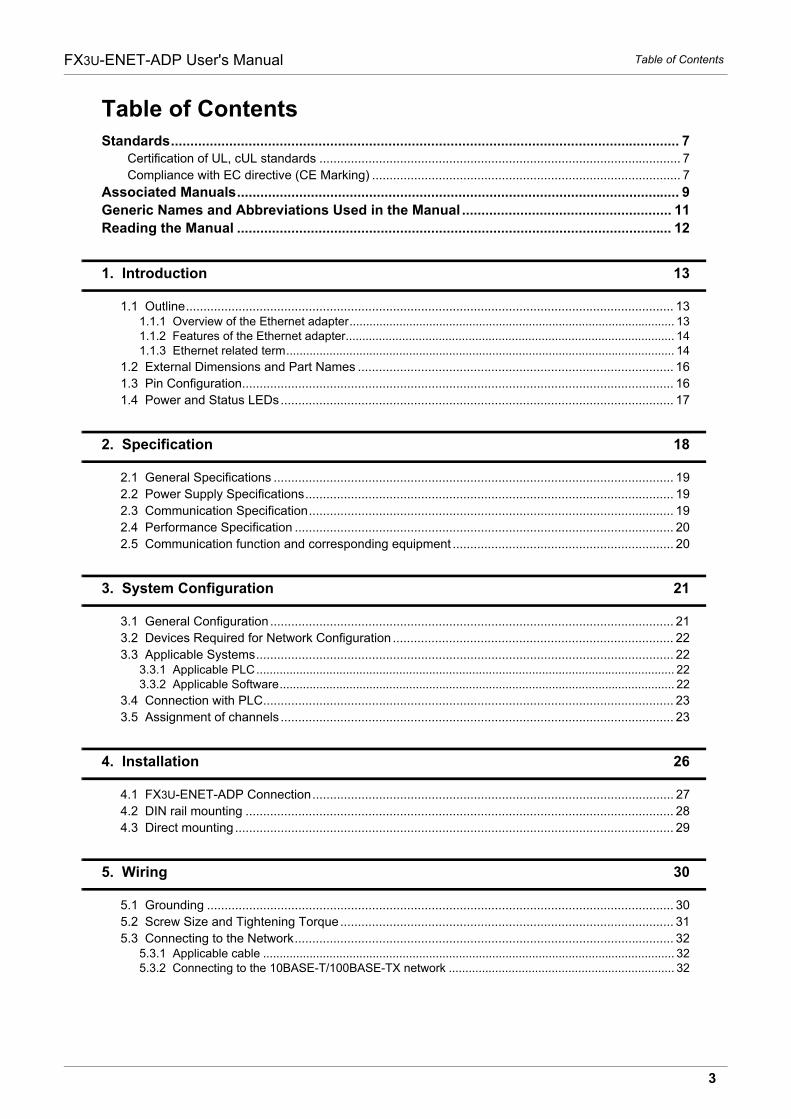
Table of Contents
Standards................................................................................................................................... 7 Certification of UL, cUL standards ....................................................................................................... 7
Compliance with EC directive (CE Marking) ........................................................................................ 7
Associated Manuals.................................................................................................................. 9
Generic Names and Abbreviations Used in the Manual ...................................................... 11
Reading the Manual ................................................................................................................ 12
1. Introduction 13
1.1 Outline........................................................................................................................................... 131.1.1 Overview of the Ethernet adapter.................................................................................................. 131.1.2 Features of the Ethernet adapter................................................................................................... 141.1.3 Ethernet related term..................................................................................................................... 14
1.2 External Dimensions and Part Names .......................................................................................... 16
1.3 Pin Configuration........................................................................................................................... 16
1.4 Power and Status LEDs................................................................................................................ 17
2. Specification 18
2.1 General Specifications .................................................................................................................. 19
2.2 Power Supply Specifications......................................................................................................... 19
2.3 Communication Specification........................................................................................................ 19
2.4 Performance Specification ............................................................................................................ 20
2.5 Communication function and corresponding equipment ............................................................... 20
3. System Configuration 21
3.1 General Configuration ................................................................................................................... 21
3.2 Devices Required for Network Configuration ................................................................................ 22
3.3 Applicable Systems....................................................................................................................... 223.3.1 Applicable PLC.............................................................................................................................. 223.3.2 Applicable Software....................................................................................................................... 22
3.4 Connection with PLC..................................................................................................................... 23
3.5 Assignment of channels ................................................................................................................ 23
4. Installation 26
4.1 FX3U-ENET-ADP Connection....................................................................................................... 27
4.2 DIN rail mounting .......................................................................................................................... 28
4.3 Direct mounting ............................................................................................................................. 29
5. Wiring 30
5.1 Grounding ..................................................................................................................................... 30
5.2 Screw Size and Tightening Torque............................................................................................... 31
5.3 Connecting to the Network............................................................................................................ 325.3.1 Applicable cable ............................................................................................................................ 325.3.2 Connecting to the 10BASE-T/100BASE-TX network .................................................................... 32
4
FX3U-ENET-ADP User's Manual Table of Contents
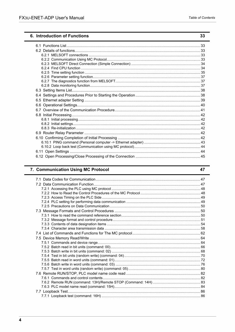
6. Introduction of Functions 33
6.1 Functions List ................................................................................................................................ 33
6.2 Details of functions........................................................................................................................ 336.2.1 MELSOFT connections ................................................................................................................. 336.2.2 Communication Using MC Protocol............................................................................................... 336.2.3 MELSOFT Direct Connection (Simple Connection) ...................................................................... 346.2.4 Find CPU function ......................................................................................................................... 346.2.5 Time setting function ..................................................................................................................... 356.2.6 Parameter setting function............................................................................................................. 376.2.7 The diagnostics function from MELSOFT...................................................................................... 376.2.8 Data monitoring function................................................................................................................ 37
6.3 Setting Items List........................................................................................................................... 38
6.4 Settings and Procedures Prior to Starting the Operation .............................................................. 38
6.5 Ethernet adapter Setting ............................................................................................................... 39
6.6 Operational Settings...................................................................................................................... 40
6.7 Overview of the Communication Procedure.................................................................................. 41
6.8 Initial Processing ........................................................................................................................... 426.8.1 Initial processing............................................................................................................................ 426.8.2 Initial settings................................................................................................................................. 426.8.3 Re-initialization .............................................................................................................................. 42
6.9 Router Relay Parameter ............................................................................................................... 42
6.10 Confirming Completion of Initial Processing ............................................................................... 426.10.1 PING command (Personal computer -> Ethernet adapter) ......................................................... 436.10.2 Loop back test (Communication using MC protocol)................................................................... 44
6.11 Open Settings ............................................................................................................................. 44
6.12 Open Processing/Close Processing of the Connection .............................................................. 45
7. Communication Using MC Protocol 47
7.1 Data Codes for Communication .................................................................................................... 47
7.2 Data Communication Function...................................................................................................... 477.2.1 Accessing the PLC using MC protocol .......................................................................................... 487.2.2 How to Read the Control Procedures of the MC Protocol ............................................................. 487.2.3 Access Timing on the PLC Side .................................................................................................... 497.2.4 PLC setting for performing data communication ........................................................................... 497.2.5 Precautions on Data Communication ............................................................................................ 50
7.3 Message Formats and Control Procedures .................................................................................. 507.3.1 How to read the command reference section................................................................................ 507.3.2 Message format and control procedure......................................................................................... 517.3.3 Contents of data designation items ............................................................................................... 547.3.4 Character area transmission data ................................................................................................. 58
7.4 List of Commands and Functions for The MC protocol................................................................. 62
7.5 Device Memory Read/Write .......................................................................................................... 647.5.1 Commands and device range........................................................................................................ 647.5.2 Batch read in bit units (command: 00)........................................................................................... 667.5.3 Batch write in bit units (command: 02) .......................................................................................... 687.5.4 Test in bit units (random write) (command: 04) ............................................................................. 707.5.5 Batch read in word units (command: 01)....................................................................................... 727.5.6 Batch write in word units (command: 03) ...................................................................................... 767.5.7 Test in word units (random write) (command: 05) ......................................................................... 80
7.6 Remote RUN/STOP, PLC model name code read ....................................................................... 827.6.1 Commands and control contents................................................................................................... 827.6.2 Remote RUN (command: 13H)/Remote STOP (Command: 14H) ................................................ 837.6.3 PLC model name read (command: 15H)....................................................................................... 84
7.7 Loopback Test............................................................................................................................... 867.7.1 Loopback test (command: 16H) .................................................................................................... 86
5
FX3U-ENET-ADP User's Manual Table of Contents
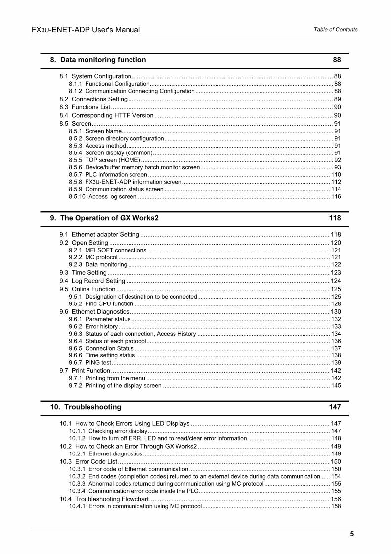
8. Data monitoring function 88
8.1 System Configuration.................................................................................................................... 888.1.1 Functional Configuration................................................................................................................ 888.1.2 Communication Connecting Configuration .................................................................................... 88
8.2 Connections Setting ...................................................................................................................... 89
8.3 Functions List ................................................................................................................................ 90
8.4 Corresponding HTTP Version ....................................................................................................... 90
8.5 Screen........................................................................................................................................... 918.5.1 Screen Name................................................................................................................................. 918.5.2 Screen directory configuration....................................................................................................... 918.5.3 Access method.............................................................................................................................. 918.5.4 Screen display (common).............................................................................................................. 918.5.5 TOP screen (HOME) ..................................................................................................................... 928.5.6 Device/buffer memory batch monitor screen................................................................................. 938.5.7 PLC information screen ............................................................................................................... 1108.5.8 FX3U-ENET-ADP information screen.......................................................................................... 1128.5.9 Communication status screen ..................................................................................................... 1148.5.10 Access log screen ..................................................................................................................... 116
9. The Operation of GX Works2 118
9.1 Ethernet adapter Setting ............................................................................................................. 118
9.2 Open Setting ............................................................................................................................... 1209.2.1 MELSOFT connections ............................................................................................................... 1219.2.2 MC protocol ................................................................................................................................. 1219.2.3 Data monitoring ........................................................................................................................... 122
9.3 Time Setting ................................................................................................................................ 123
9.4 Log Record Setting ..................................................................................................................... 124
9.5 Online Function ........................................................................................................................... 1259.5.1 Designation of destination to be connected................................................................................. 1259.5.2 Find CPU function ....................................................................................................................... 128
9.6 Ethernet Diagnostics ................................................................................................................... 1309.6.1 Parameter status ......................................................................................................................... 1329.6.2 Error history ................................................................................................................................. 1339.6.3 Status of each connection, Access History ................................................................................. 1349.6.4 Status of each protocol................................................................................................................ 1369.6.5 Connection Status ....................................................................................................................... 1379.6.6 Time setting status ...................................................................................................................... 1389.6.7 PING test ..................................................................................................................................... 139
9.7 Print Function .............................................................................................................................. 1429.7.1 Printing from the menu ................................................................................................................ 1429.7.2 Printing of the display screen ...................................................................................................... 145
10. Troubleshooting 147
10.1 How to Check Errors Using LED Displays ................................................................................ 14710.1.1 Checking error display............................................................................................................... 14710.1.2 How to turn off ERR. LED and to read/clear error information .................................................. 148
10.2 How to Check an Error Through GX Works2 ............................................................................ 14910.2.1 Ethernet diagnostics .................................................................................................................. 149
10.3 Error Code List .......................................................................................................................... 15010.3.1 Error code of Ethernet communication ...................................................................................... 15010.3.2 End codes (completion codes) returned to an external device during data communication ..... 15410.3.3 Abnormal codes returned during communication using MC protocol ........................................ 15510.3.4 Communication error code inside the PLC................................................................................ 155
10.4 Troubleshooting Flowchart........................................................................................................ 15610.4.1 Errors in communication using MC protocol.............................................................................. 158
6
FX3U-ENET-ADP User's Manual Table of Contents
Appendix A: List of the Special Devices 160
Appendix B: Version Information 162
Appendix B-1 Version check method........................................................................................ 162
Appendix B-2 Version upgrade history ..................................................................................... 162
Appendix C: Program Examples 164
Appendix C-1 Program example for communication using MC protocol -1 .............................. 165
Appendix C-2 Program example for communication using MC protocol -2 .............................. 171
Appendix D: Differences with FX3U-ENET 175
Appendix E: Document, others 177
Appendix E-1 Setting Value Recording Sheets ........................................................................ 177
Appendix E-2 Processing Time ................................................................................................ 181
Appendix E-3 ASCII Code List.................................................................................................. 182
Appendix E-4 References......................................................................................................... 183
Appendix E-5 Differences between Ethernet and IEEE802.3................................................... 183
Appendix E-6 ICMP Protocol Supported by Ethernet adapter .................................................. 183
Warranty................................................................................................................................. 185
Revised History ..................................................................................................................... 186

Standards
7
FX3U-ENET-ADP User's Manual
Standards
Certification of UL, cUL standards
FX3U-ENET-ADP units comply with the UL standards (UL, cUL).
UL, cUL File number :E95239
Regarding the standards that comply with the main unit, please refer to either the FX series product catalog orconsult with your nearest Mitsubishi product provider.
Compliance with EC directive (CE Marking)
This document does not guarantee that a mechanical system including this product will comply with thefollowing standards.Compliance to EMC directive and LVD directive for the entire mechanical module should be checked by theuser / manufacturer. For more information please consult with your nearest Mitsubishi product provider.Regarding the standards that comply with the main unit, please refer to either the FX series product catalog orconsult with your nearest Mitsubishi product provider.
Requirement for Compliance with EMC directive
The following products have shown compliance through direct testing (of the identified standards below) and design analysis (through the creation of a technical construction file) to the European Directive for Electromagnetic Compatibility (2004/108/EC) when used as directed by the appropriate documentation.
Attention
� This product is designed for use in industrial applications.
Note
� Manufactured by:Mitsubishi Electric Corporation2-7-3 Marunouchi, Chiyoda-ku, Tokyo, 100-8310 Japan
� Manufactured at:Mitsubishi Electric Corporation Himeji Works840 Chiyoda-machi, Himeji, Hyogo, 670-8677 Japan
� Authorized Representative in the European Community:Mitsubishi Electric Europe B.V.Gothaer Str. 8, 40880 Ratingen, Germany
Type: Programmable Controller (Open Type Equipment)Models: MELSEC FX3U series manufactured from February 1st, 2012 FX3U-ENET-ADP
Standard Remark
EN61131-2:2007
Programmable controllers
- Equipment requirements and tests
Compliance with all relevant aspects of the standard.
EMI
� Radiated Emission
� Conducted Emission
EMS
� Radiated electromagnetic field
� Fast transient burst
� Electrostatic discharge
� High-energy surge
� Voltage drops and interruptions
� Conducted RF
� Power frequency magnetic field
Standards
8
FX3U-ENET-ADP User's Manual
Caution to conform with EC Directives
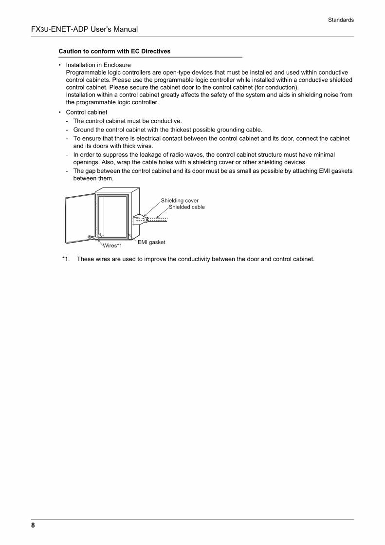
� Installation in EnclosureProgrammable logic controllers are open-type devices that must be installed and used within conductive control cabinets. Please use the programmable logic controller while installed within a conductive shielded control cabinet. Please secure the cabinet door to the control cabinet (for conduction).Installation within a control cabinet greatly affects the safety of the system and aids in shielding noise from the programmable logic controller.
� Control cabinet
- The control cabinet must be conductive.
- Ground the control cabinet with the thickest possible grounding cable.
- To ensure that there is electrical contact between the control cabinet and its door, connect the cabinet and its doors with thick wires.
- In order to suppress the leakage of radio waves, the control cabinet structure must have minimal openings. Also, wrap the cable holes with a shielding cover or other shielding devices.
- The gap between the control cabinet and its door must be as small as possible by attaching EMI gaskets between them.
*1. These wires are used to improve the conductivity between the door and control cabinet.
Shielding coverShielded cable
Wires*1EMI gasket
Associated Manuals
9
FX3U-ENET-ADP User's Manual
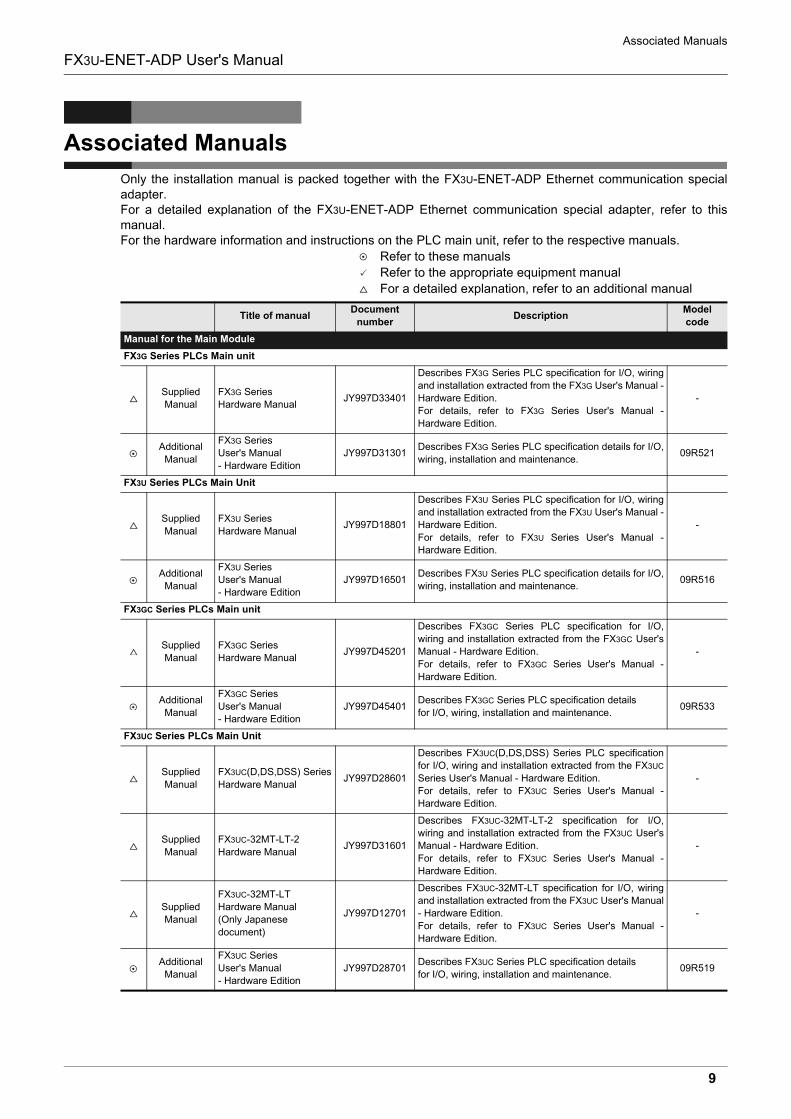
Associated Manuals
Only the installation manual is packed together with the FX3U-ENET-ADP Ethernet communication specialadapter.For a detailed explanation of the FX3U-ENET-ADP Ethernet communication special adapter, refer to thismanual.For the hardware information and instructions on the PLC main unit, refer to the respective manuals.
Refer to these manuals
Refer to the appropriate equipment manual
For a detailed explanation, refer to an additional manual
Title of manualDocument
numberDescription
Model
code
Manual for the Main Module
FX3G Series PLCs Main unit
Supplied
Manual
FX3G Series
Hardware ManualJY997D33401
Describes FX3G Series PLC specification for I/O, wiring
and installation extracted from the FX3G User's Manual -
Hardware Edition.
For details, refer to FX3G Series User's Manual -
Hardware Edition.
-
Additional
Manual
FX3G Series
User's Manual
- Hardware Edition
JY997D31301Describes FX3G Series PLC specification details for I/O,
wiring, installation and maintenance.09R521
FX3U Series PLCs Main Unit
Supplied
Manual
FX3U Series
Hardware ManualJY997D18801
Describes FX3U Series PLC specification for I/O, wiring
and installation extracted from the FX3U User's Manual -
Hardware Edition.
For details, refer to FX3U Series User's Manual -
Hardware Edition.
-
Additional
Manual
FX3U Series
User's Manual
- Hardware Edition
JY997D16501Describes FX3U Series PLC specification details for I/O,
wiring, installation and maintenance.09R516
FX3GC Series PLCs Main unit
Supplied
Manual
FX3GC Series
Hardware ManualJY997D45201
Describes FX3GC Series PLC specification for I/O,
wiring and installation extracted from the FX3GC User's
Manual - Hardware Edition.
For details, refer to FX3GC Series User's Manual -
Hardware Edition.
-
Additional
Manual
FX3GC Series
User's Manual
- Hardware Edition
JY997D45401Describes FX3GC Series PLC specification details
for I/O, wiring, installation and maintenance.09R533
FX3UC Series PLCs Main Unit
Supplied
Manual
FX3UC(D,DS,DSS) Series
Hardware ManualJY997D28601
Describes FX3UC(D,DS,DSS) Series PLC specification
for I/O, wiring and installation extracted from the FX3UC
Series User's Manual - Hardware Edition.
For details, refer to FX3UC Series User's Manual -
Hardware Edition.
-
Supplied
Manual
FX3UC-32MT-LT-2
Hardware ManualJY997D31601
Describes FX3UC-32MT-LT-2 specification for I/O,
wiring and installation extracted from the FX3UC User's
Manual - Hardware Edition.
For details, refer to FX3UC Series User's Manual -
Hardware Edition.
-
Supplied
Manual
FX3UC-32MT-LT
Hardware Manual
(Only Japanese
document)
JY997D12701
Describes FX3UC-32MT-LT specification for I/O, wiring
and installation extracted from the FX3UC User's Manual
- Hardware Edition.
For details, refer to FX3UC Series User's Manual -
Hardware Edition.
-
Additional
Manual
FX3UC Series
User's Manual
- Hardware Edition
JY997D28701Describes FX3UC Series PLC specification details
for I/O, wiring, installation and maintenance.09R519
Associated Manuals
10
FX3U-ENET-ADP User's Manual
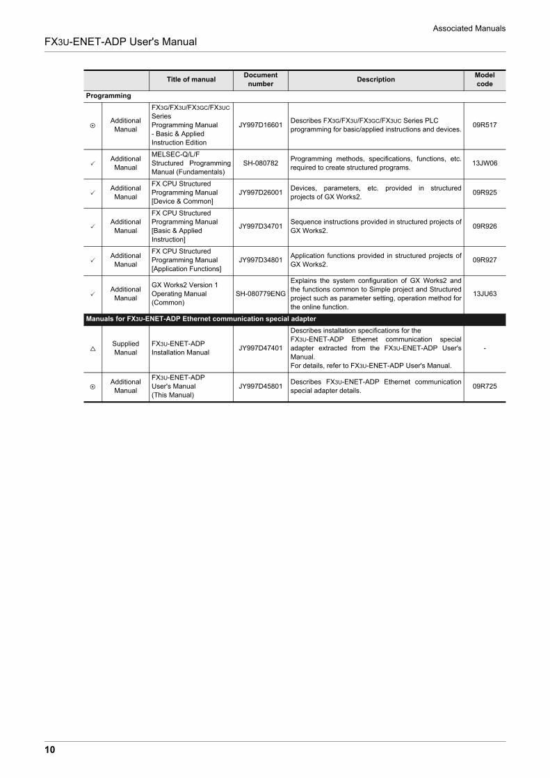
Programming
Additional
Manual
FX3G/FX3U/FX3GC/FX3UC
Series
Programming Manual
- Basic & Applied
Instruction Edition
JY997D16601Describes FX3G/FX3U/FX3GC/FX3UC Series PLC
programming for basic/applied instructions and devices.09R517
Additional
Manual
MELSEC-Q/L/F
Structured Programming
Manual (Fundamentals)
SH-080782Programming methods, specifications, functions, etc.
required to create structured programs.13JW06
Additional
Manual
FX CPU Structured
Programming Manual
[Device & Common]
JY997D26001Devices, parameters, etc. provided in structured
projects of GX Works2.09R925
Additional
Manual
FX CPU Structured
Programming Manual
[Basic & Applied
Instruction]
JY997D34701Sequence instructions provided in structured projects of
GX Works2.09R926
Additional
Manual
FX CPU Structured
Programming Manual
[Application Functions]
JY997D34801Application functions provided in structured projects of
GX Works2.09R927
Additional
Manual
GX Works2 Version 1
Operating Manual
(Common)
SH-080779ENG
Explains the system configuration of GX Works2 and
the functions common to Simple project and Structured
project such as parameter setting, operation method for
the online function.
13JU63
Manuals for FX3U-ENET-ADP Ethernet communication special adapter
Supplied
Manual
FX3U-ENET-ADP
Installation ManualJY997D47401
Describes installation specifications for the
FX3U-ENET-ADP Ethernet communication special
adapter extracted from the FX3U-ENET-ADP User's
Manual.
For details, refer to FX3U-ENET-ADP User's Manual.
-
Additional
Manual
FX3U-ENET-ADP
User's Manual
(This Manual)
JY997D45801Describes FX3U-ENET-ADP Ethernet communication
special adapter details.09R725
Title of manualDocument
numberDescription
Model
code
Generic Names and Abbreviations Used in the Manual
11
FX3U-ENET-ADP User's Manual
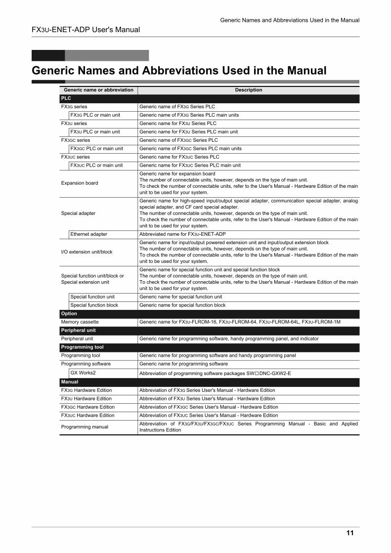
Generic Names and Abbreviations Used in the Manual
Generic name or abbreviation Description
PLC
FX3G series Generic name of FX3G Series PLC
FX3G PLC or main unit Generic name of FX3G Series PLC main units
FX3U series Generic name for FX3U Series PLC
FX3U PLC or main unit Generic name for FX3U Series PLC main unit
FX3GC series Generic name of FX3GC Series PLC
FX3GC PLC or main unit Generic name of FX3GC Series PLC main units
FX3UC series Generic name for FX3UC Series PLC
FX3UC PLC or main unit Generic name for FX3UC Series PLC main unit
Expansion board
Generic name for expansion board
The number of connectable units, however, depends on the type of main unit.
To check the number of connectable units, refer to the User's Manual - Hardware Edition of the main
unit to be used for your system.
Special adapter
Generic name for high-speed input/output special adapter, communication special adapter, analog
special adapter, and CF card special adapter.
The number of connectable units, however, depends on the type of main unit.
To check the number of connectable units, refer to the User's Manual - Hardware Edition of the main
unit to be used for your system.
Ethernet adapter Abbreviated name for FX3U-ENET-ADP
I/O extension unit/block
Generic name for input/output powered extension unit and input/output extension block
The number of connectable units, however, depends on the type of main unit.
To check the number of connectable units, refer to the User's Manual - Hardware Edition of the main
unit to be used for your system.
Special function unit/block or
Special extension unit
Generic name for special function unit and special function block
The number of connectable units, however, depends on the type of main unit.
To check the number of connectable units, refer to the User's Manual - Hardware Edition of the main
unit to be used for your system.
Special function unit Generic name for special function unit
Special function block Generic name for special function block
Option
Memory cassette Generic name for FX3U-FLROM-16, FX3U-FLROM-64, FX3U-FLROM-64L, FX3U-FLROM-1M
Peripheral unit
Peripheral unit Generic name for programming software, handy programming panel, and indicator
Programming tool
Programming tool Generic name for programming software and handy programming panel
Programming software Generic name for programming software
GX Works2 Abbreviation of programming software packages SW DNC-GXW2-E
Manual
FX3G Hardware Edition Abbreviation of FX3G Series User's Manual - Hardware Edition
FX3U Hardware Edition Abbreviation of FX3U Series User's Manual - Hardware Edition
FX3GC Hardware Edition Abbreviation of FX3GC Series User's Manual - Hardware Edition
FX3UC Hardware Edition Abbreviation of FX3UC Series User's Manual - Hardware Edition
Programming manualAbbreviation of FX3G/FX3U/FX3GC/FX3UC Series Programming Manual - Basic and Applied
Instructions Edition
Reading the Manual
12
FX3U-ENET-ADP User's Manual
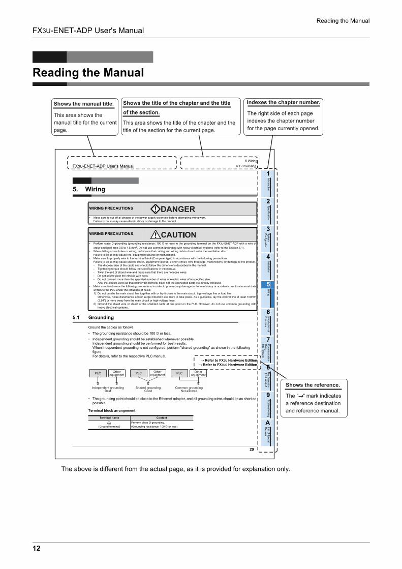
Reading the Manual
The above is different from the actual page, as it is provided for explanation only.
This area shows the title of the chapter and the
title of the section for the current page.
The right side of each page
indexes the chapter number
for the page currently opened.
This area shows the
manual title for the current
page.
The " " mark indicates
a reference destination
and reference manual.
Shows the reference.
Indexes the chapter number.Shows the title of the chapter and the title
of the section.
Shows the manual title.
1 Introduction
1.1 Outline
13
FX3U-ENET-ADP User's Manual
1
Introduction
2
Specification
3
System
C
onfiguration
4
Installation
5
Wiring
6
Introduction of F
unctions
7
Com
munication
Using
MC
Protocol
8
Data m
onitoring function
9
The O
peration of G
X W
orks2
10
Troubleshooting
1. Introduction
1.1 Outline
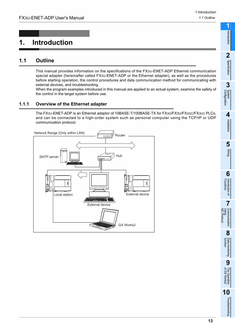
This manual provides information on the specifications of the FX3U-ENET-ADP Ethernet communicationspecial adapter (hereinafter called FX3U-ENET-ADP or the Ethernet adapter), as well as the proceduresbefore starting operation, the control procedures and data communication method for communicating withexternal devices, and troubleshooting.When the program examples introduced in this manual are applied to an actual system, examine the safety ofthe control in the target system before use.
1.1.1 Overview of the Ethernet adapter
The FX3U-ENET-ADP is an Ethernet adaptor of 10BASE-T/100BASE-TX for FX3G/FX3U/FX3GC/FX3UC PLCs,and can be connected to a high-order system such as personal computer using the TCP/IP or UDPcommunication protocol.
GX Works2
Network Range (Only within LAN)
SNTP server
Local station
External device
External device
Hub
Router
1 Introduction
1.1 Outline
14
FX3U-ENET-ADP User's Manual
1.1.2 Features of the Ethernet adapter
The Ethernet adapter has the following features.
1) Users can read and write data and programs from/to the PLC using MELSOFT products such as GXWorks2 within the company LAN, etc.
2) Users can develop custom software to communicate with the PLC by using MC (MELSECCommunication) protocol (A-compatible 1E frame subset, for details, refer to user's manual). (TCP/IP orUDP/IP)
3) The FX3U-ENET-ADP can be connected directly (simple connection) to GX Works2 with only oneEthernet cable without using the hub.
4) Users can search "FX3U-ENET-ADP + Main unit" connected in the network using the find CPU function ofGX Works2.
5) The FX3U-ENET-ADP can automatically set the time of the main unit using the time setting function.
6) The FX3U-ENET-ADP parameters can be set easily using GX Works2.
7) The diagnostic functions of GX Works2 enables easy diagnostics and troubleshooting of the FX3U-ENET-ADP.
8) Users can monitor the information and device values stored in the main unit and FX3U-ENET-ADP fromthe browser in the personal computer using the data monitoring function.
1.1.3 Ethernet related term
1) TCP (Transmission Control Protocol)This protocol guarantees data credibility and reliability in communication between a personal computer/work station and PLC that are connected via network, and provides the following functions:
- Creates a logical connection by establishing a connection (logical line) as if a dedicated line was created between external devices.
- Up to 4 connections can be established and used at the same time in the Ethernet adapter.
- Data reliability is maintained by sequence control using the sequence numbers, the data retransmission function and check sum.
- Communication data flow can be controlled by Windows operations.
2) UDP (User Datagram Protocol)This protocol may not guarantee data credibility or reliability in communication between a personalcomputer/work station and PLC that are connected via network. Thus, even if the data does not reach thetarget node, it will not be retransmitted.
- Because it is connectionless, communication efficiency is much improved than TCP/IP.
- A check sum is used to increase the reliability of the communication data. When greater reliability must be maintained, a user application or TCP should be used for the retrying operation.
3) IP (Internet Protocol)
- Communication data is sent and received in datagram format.
- Communication data can be divided and reassembled.
- Routing option is not supported.
4) ARP (Address Resolution Protocol)
- This protocol is used to get the Ethernet physical addresses from the IP addresses.
5) ICMP (Internet Control Message Protocol)
- This protocol is used to exchange errors which occur on an IP network and various information related to the network.
- Provides a function to transmit IP error messages.
- Refer to Appendix E-6 for information regarding the types of ICMP supported.
1 Introduction
1.1 Outline
15
FX3U-ENET-ADP User's Manual
1
Introduction
2
Specification
3
System
C
onfiguration
4
Installation
5
Wiring
6
Introduction of F
unctions
7
Com
munication
Using
MC
Protocol
8
Data m
onitoring function
9
The O
peration of G
X W
orks2
10
Troubleshooting
6) Flag bit of TCP/IP (SYN, ACK, PSH, FIN, RST, and URG)In communication using TCP, these flag bits indicate segments where connection/disconnection orresponse confirmation is executed or emergency data is included.
a) SYN (Synchronized Flag)When this bit is ON (1), it indicates that the initial sequence number value is set in the sequencenumber field. This bit is used when the connection is newly opened.
b) ACK (Acknowledgment Flag)When this bit is ON (1), it indicates that ACK (confirmation response number) field is valid. It also indicates that this segment includes the information on response confirmation. When this bit is OFF (0), it indicates that ACK (confirmation response number) field is invalid.
c) PSH (Push Flag)When this bit is ON (1), the host that has received this segment sends the data to the upperapplication with high priority.This bit is to be turned ON when the data should be sent to an external device as soon as possible. When this bit is OFF (0), the timing when the received data is sent to the upper application dependson the TCP layer of the receiving side.
d) FIN (Fin Flag)When this bit is ON (1), it indicates that there is no more data to be sent from the segment source andthat the send source wants to disconnect. However, data still can be received from the external device. The connection is on until the segment whose FIN bit is ON is received from the external device.
e) RST (Reset Flag)When this bit is ON (1), the host from which the segment has sent disconnects unilaterally (forcibly). Disconnection by this method is used when an unrecoverable error with the normal method hasoccurred or when the host has been restored after being down.
f) URG (Urgent Flag)When this bit is ON (1), it indicates that this data segment includes the emergency data flag.
1 Introduction
1.2 External Dimensions and Part Names
16
FX3U-ENET-ADP User's Manual
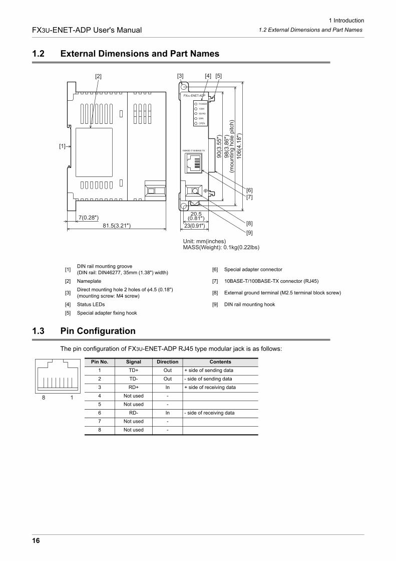
1.2 External Dimensions and Part Names
1.3 Pin Configuration
The pin configuration of FX3U-ENET-ADP RJ45 type modular jack is as follows:
[1]DIN rail mounting groove
(DIN rail: DIN46277, 35mm (1.38") width)[6] Special adapter connector
[2] Nameplate [7] 10BASE-T/100BASE-TX connector (RJ45)
[3]Direct mounting hole 2 holes of φ4.5 (0.18")
(mounting screw: M4 screw)[8] External ground terminal (M2.5 terminal block screw)
[4] Status LEDs [9] DIN rail mounting hook
[5] Special adapter fixing hook
Pin No. Signal Direction Contents
1 TD+ Out + side of sending data
2 TD- Out - side of sending data
3 RD+ In + side of receiving data
4 Not used -
5 Not used -
6 RD- In - side of receiving data
7 Not used -
8 Not used -
[2]
Unit: mm(inches)MASS(Weight): 0.1kg(0.22lbs)
[1]
90
(3.5
5″)
10
6(4
.18″)
23(0.91″)
20.5(0.81″)
[7][6]
[9]
[8]
[5][4]
7(0.28″)81.5(3.21″)
98
(3.8
6″)
(mo
un
tin
g h
ole
pitch
)
[3]
8 1
1 Introduction
1.4 Power and Status LEDs
17
FX3U-ENET-ADP User's Manual
1
Introduction
2
Specification
3
System
C
onfiguration
4
Installation
5
Wiring
6
Introduction of F
unctions
7
Com
munication
Using
MC
Protocol
8
Data m
onitoring function
9
The O
peration of G
X W
orks2
10
Troubleshooting
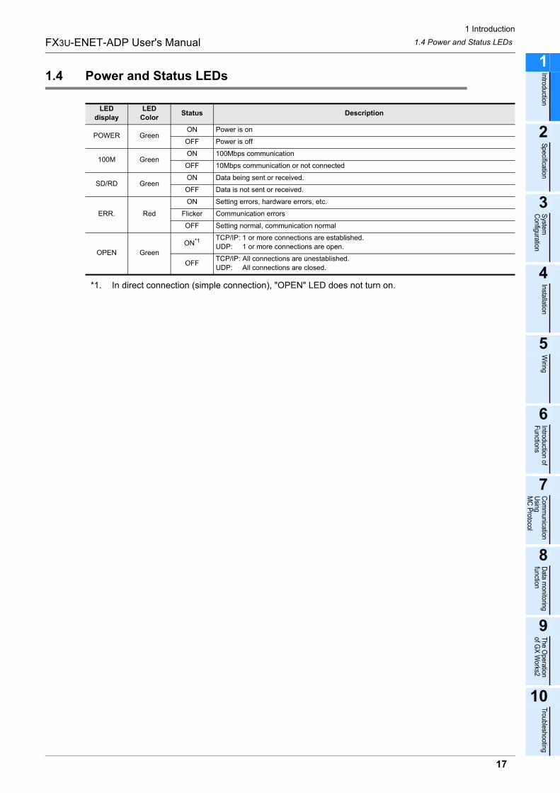
1.4 Power and Status LEDs
*1. In direct connection (simple connection), "OPEN" LED does not turn on.
LED
display
LED
ColorStatus Description
POWER GreenON Power is on
OFF Power is off
100M GreenON 100Mbps communication
OFF 10Mbps communication or not connected
SD/RD GreenON Data being sent or received.
OFF Data is not sent or received.
ERR. Red
ON Setting errors, hardware errors, etc.
Flicker Communication errors
OFF Setting normal, communication normal
OPEN Green
ON*1 TCP/IP: 1 or more connections are established.
UDP: 1 or more connections are open.
OFFTCP/IP: All connections are unestablished.
UDP: All connections are closed.
2 Specification
18
FX3U-ENET-ADP User's Manual
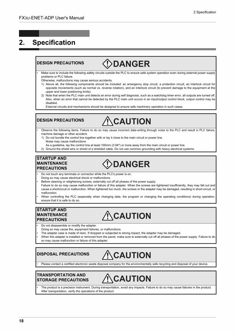
2. Specification
DESIGN PRECAUTIONS
� Make sure to include the following safety circuits outside the PLC to ensure safe system operation even during external power supply
problems or PLC failure.
Otherwise, malfunctions may cause serious accidents.
1) Above all, the following components should be included: an emergency stop circuit, a protection circuit, an interlock circuit for
opposite movements (such as normal vs. reverse rotation), and an interlock circuit (to prevent damage to the equipment at the
upper and lower positioning limits).
2) Note that when the PLC main unit detects an error during self diagnosis, such as a watchdog timer error, all outputs are turned off.
Also, when an error that cannot be detected by the PLC main unit occurs in an input/output control block, output control may be
disabled.
External circuits and mechanisms should be designed to ensure safe machinery operation in such cases.
DESIGN PRECAUTIONS
� Observe the following items. Failure to do so may cause incorrect data-writing through noise to the PLC and result in PLC failure,
machine damage or other accident.
1) Do not bundle the control line together with or lay it close to the main circuit or power line.
Noise may cause malfunctions.
As a guideline, lay the control line at least 100mm (3.94") or more away from the main circuit or power line.
2) Ground the shield wire or shield of a shielded cable. Do not use common grounding with heavy electrical systems.
STARTUP AND MAINTENANCE PRECAUTIONS
� Do not touch any terminals or connector while the PLC's power is on.
Doing so may cause electrical shock or malfunctions.
� Before cleaning or retightening screws, externally cut off all phases of the power supply.
Failure to do so may cause malfunction or failure of this adapter. When the screws are tightened insufficiently, they may fall out and
cause a shortcircuit or malfunction. When tightened too much, the screws or the adapter may be damaged, resulting in short-circuit, or
malfunction.
� When controlling the PLC (especially when changing data, the program or changing the operating conditions) during operation,
ensure that it is safe to do so.
STARTUP AND MAINTENANCE PRECAUTIONS
� Do not disassemble or modify the adapter.
Doing so may cause fire, equipment failures, or malfunctions.
� The adapter case is made of resin. If dropped or subjected to strong impact, the adapter may be damaged.
� When this adapter is installed or removed from the panel, make sure to externally cut off all phases of the power supply. Failure to do
so may cause malfunction or failure of this adapter.
DISPOSAL PRECAUTIONS
� Please contact a certified electronic waste disposal company for the environmentally safe recycling and disposal of your device.
TRANSPORTATION AND STORAGE PRECAUTIONS
� The product is a precision instrument. During transportation, avoid any impacts. Failure to do so may cause failures in the product.
After transportation, verify the operations of the product.
2 Specification
19
FX3U-ENET-ADP User's Manual
1
Introduction
2
Specification
3
System
C
onfiguration
4
Installation
5
Wiring
6
Introduction of F
unctions
7
Com
munication
Using
MC
Protocol
8
Data m
onitoring function
9
The O
peration of G
X W
orks2
10
Troubleshooting
2.1 General Specifications
2.1 General Specifications
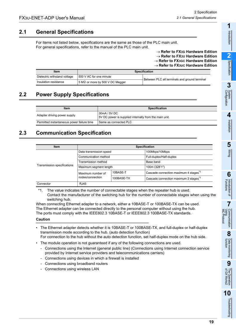
For items not listed below, specifications are the same as those of the PLC main unit.For general specifications, refer to the manual of the PLC main unit.
→ Refer to FX3G Hardware Edition→ Refer to FX3U Hardware Edition
→ Refer to FX3GC Hardware Edition→ Refer to FX3UC Hardware Edition
2.2 Power Supply Specifications
2.3 Communication Specification
*1. The value indicates the number of connectable stages when the repeater hub is used.Contact the manufacturer of the switching hub for the number of connectable stages when using theswitching hub.
When connecting Ethernet adapter to a network, either a 10BASE-T or 100BASE-TX can be used.The Ethernet adapter can be connected directly to the personal computer without using the hub.The ports must comply with the IEEE802.3 10BASE-T or IEEE802.3 100BASE-TX standards.
Caution
� The Ethernet adapter detects whether it is 10BASE-T or 100BASE-TX, and full-duplex or half-duplex transmission mode according to the hub. (auto detection function)For connection to the hub without the auto detection function, set half-duplex mode on the hub side.
� The module operation is not guaranteed if any of the following connections are used.
- Connections using the Internet (general public line) (Connections using Internet connection service provided by Internet service providers and telecommunications carriers)
- Connections using devices in which a firewall is installed
- Connections using broadband routers
- Connections using wireless LAN
Item Specification
Dielectric withstand voltage 500 V AC for one minuteBetween PLC all terminals and ground terminal
Insulation resistance 5 M or more by 500 V DC Megger
Item Specification
Adapter driving power supply30mA / 5V DC
5V DC power is supplied internally from the main unit.
Permitted instantaneous power failure time Same as connected PLC
Item Specification
Transmission specifications
Data transmission speed 100Mbps/10Mbps
Communication method Full-duplex/Half-duplex
Transmission method Base band
Maximum segment length 100m (328’1")
Maximum number of
nodes/connection
10BASE-T Cascade connection maximum 4 stages*1
100BASE-TX Cascade connection maximum 2 stages*1
Connector RJ45
2 Specification
20
FX3U-ENET-ADP User's Manual 2.4 Performance Specification
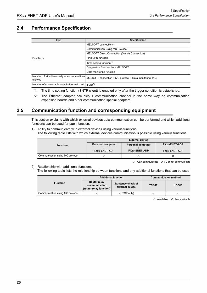
2.4 Performance Specification
*1. The time setting function (SNTP client) is enabled only after the trigger condition is established.
*2. The Ethernet adapter occupies 1 communication channel in the same way as communicationexpansion boards and other communication special adapters.
2.5 Communication function and corresponding equipment
This section explains with which external devices data communication can be performed and which additionalfunctions can be used for each function.
1) Ability to communicate with external devices using various functionsThe following table lists with which external devices communication is possible using various functions.
: Can communicate : Cannot communicate
2) Relationship with additional functionsThe following table lists the relationship between functions and any additional functions that can be used.
: Available : Not available
Item Specification
Functions
MELSOFT connections
Communication Using MC Protocol
MELSOFT Direct Connection (Simple Connection)
Find CPU function
Time setting function*1
Diagnostics function from MELSOFT
Data monitoring function
Number of simultaneously open connections
allowedMELSOFT connection + MC protocol + Data monitoring <= 4
Number of connectable units to the main unit 1 unit*2
Function
External device
Personal computer
FX3U-ENET-ADP
Personal computer
FX3U-ENET-ADP
FX3U-ENET-ADP
FX3U-ENET-ADP
Communication using MC protocol
Function
Additional function Communication method
Router relay
communication
(router relay function)
Existence check of
external deviceTCP/IP UDP/IP
Communication using MC protocol (TCP only)
3 System Configuration
3.1 General Configuration
21
FX3U-ENET-ADP User's Manual
1
Introduction
2
Specification
3
System
C
onfiguration
4
Installation
5
Wiring
6
Introduction of F
unctions
7
Com
munication
Using
MC
Protocol
8
Data m
onitoring function
9
The O
peration of G
X W
orks2
10
Troubleshooting
3. System Configuration
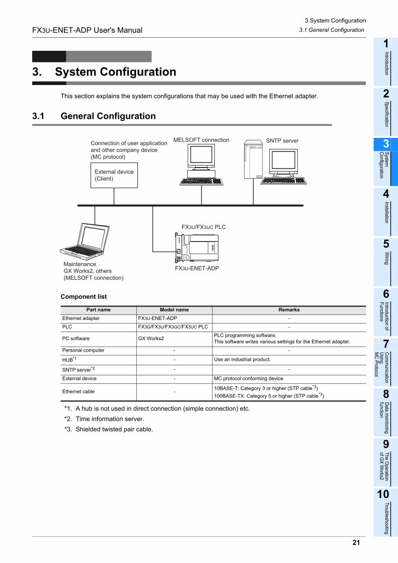
This section explains the system configurations that may be used with the Ethernet adapter.
3.1 General Configuration
Component list
*1. A hub is not used in direct connection (simple connection) etc.
*2. Time information server.
*3. Shielded twisted pair cable.
Part name Model name Remarks
Ethernet adapter FX3U-ENET-ADP -
PLC FX3G/FX3U/FX3GC/FX3UC PLC -
PC software GX Works2PLC programming software.
This software writes various settings for the Ethernet adapter.
Personal computer - -
HUB*1 - Use an industrial product.
SNTP server*2 - -
External device - MC protocol conforming device
Ethernet cable -10BASE-T: Category 3 or higher (STP cable*3)
100BASE-TX: Category 5 or higher (STP cable*3)
FX3U/FX3UC PLC
MELSOFT connection SNTP server
FX3U-ENET-ADP
Connection of user application and other company device(MC protocol)
External device(Client)
MaintenanceGX Works2, others (MELSOFT connection)
3 System Configuration
3.2 Devices Required for Network Configuration
22
FX3U-ENET-ADP User's Manual
3.2 Devices Required for Network Configuration
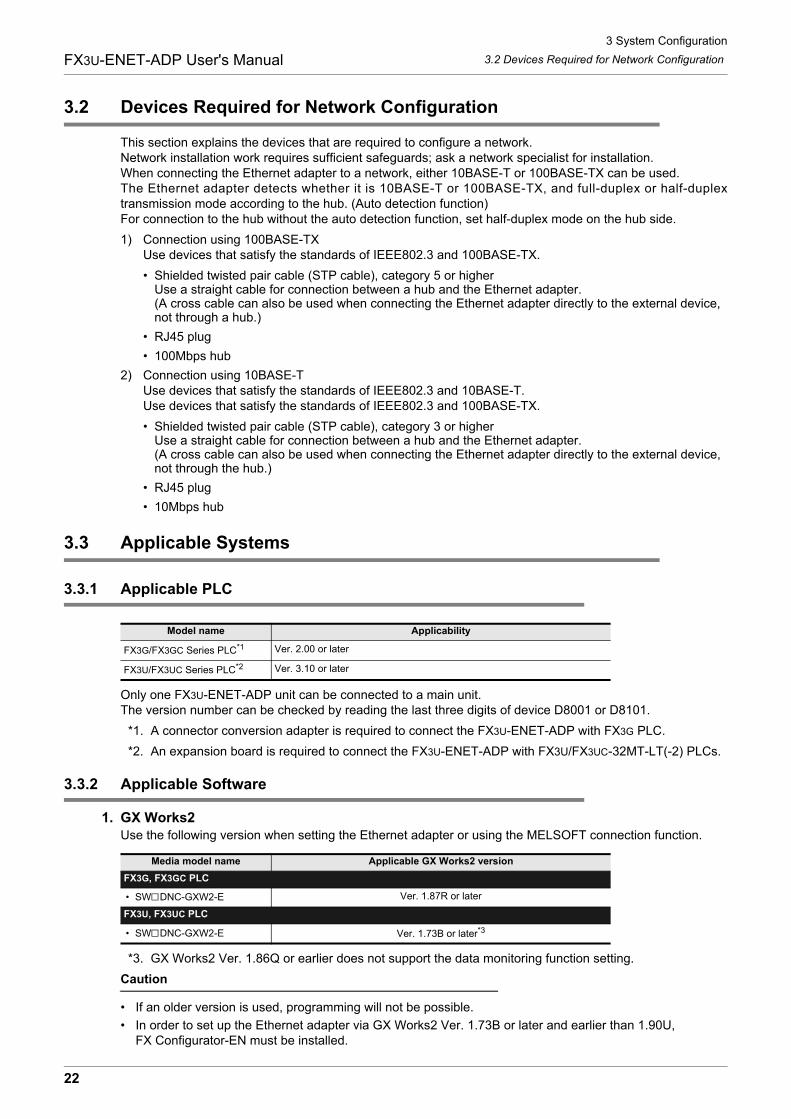
This section explains the devices that are required to configure a network.Network installation work requires sufficient safeguards; ask a network specialist for installation.When connecting the Ethernet adapter to a network, either 10BASE-T or 100BASE-TX can be used.The Ethernet adapter detects whether it is 10BASE-T or 100BASE-TX, and full-duplex or half-duplextransmission mode according to the hub. (Auto detection function)For connection to the hub without the auto detection function, set half-duplex mode on the hub side.
1) Connection using 100BASE-TXUse devices that satisfy the standards of IEEE802.3 and 100BASE-TX.
� Shielded twisted pair cable (STP cable), category 5 or higherUse a straight cable for connection between a hub and the Ethernet adapter.(A cross cable can also be used when connecting the Ethernet adapter directly to the external device, not through a hub.)
� RJ45 plug
� 100Mbps hub
2) Connection using 10BASE-TUse devices that satisfy the standards of IEEE802.3 and 10BASE-T.Use devices that satisfy the standards of IEEE802.3 and 100BASE-TX.
� Shielded twisted pair cable (STP cable), category 3 or higherUse a straight cable for connection between a hub and the Ethernet adapter.(A cross cable can also be used when connecting the Ethernet adapter directly to the external device, not through the hub.)
� RJ45 plug
� 10Mbps hub
3.3 Applicable Systems
3.3.1 Applicable PLC
Only one FX3U-ENET-ADP unit can be connected to a main unit.The version number can be checked by reading the last three digits of device D8001 or D8101.
*1. A connector conversion adapter is required to connect the FX3U-ENET-ADP with FX3G PLC.
*2. An expansion board is required to connect the FX3U-ENET-ADP with FX3U/FX3UC-32MT-LT(-2) PLCs.
3.3.2 Applicable Software
1. GX Works2Use the following version when setting the Ethernet adapter or using the MELSOFT connection function.
*3. GX Works2 Ver. 1.86Q or earlier does not support the data monitoring function setting.
Caution
� If an older version is used, programming will not be possible.
� In order to set up the Ethernet adapter via GX Works2 Ver. 1.73B or later and earlier than 1.90U, FX Configurator-EN must be installed.
Model name Applicability
FX3G/FX3GC Series PLC*1 Ver. 2.00 or later
FX3U/FX3UC Series PLC*2 Ver. 3.10 or later
Media model name Applicable GX Works2 version
FX3G, FX3GC PLC
� SW DNC-GXW2-E Ver. 1.87R or later
FX3U, FX3UC PLC
� SW DNC-GXW2-E Ver. 1.73B or later*3
3 System Configuration
3.4 Connection with PLC
23
FX3U-ENET-ADP User's Manual
1
Introduction
2
Specification
3
System
C
onfiguration
4
Installation
5
Wiring
6
Introduction of F
unctions
7
Com
munication
Using
MC
Protocol
8
Data m
onitoring function
9
The O
peration of G
X W
orks2
10
Troubleshooting
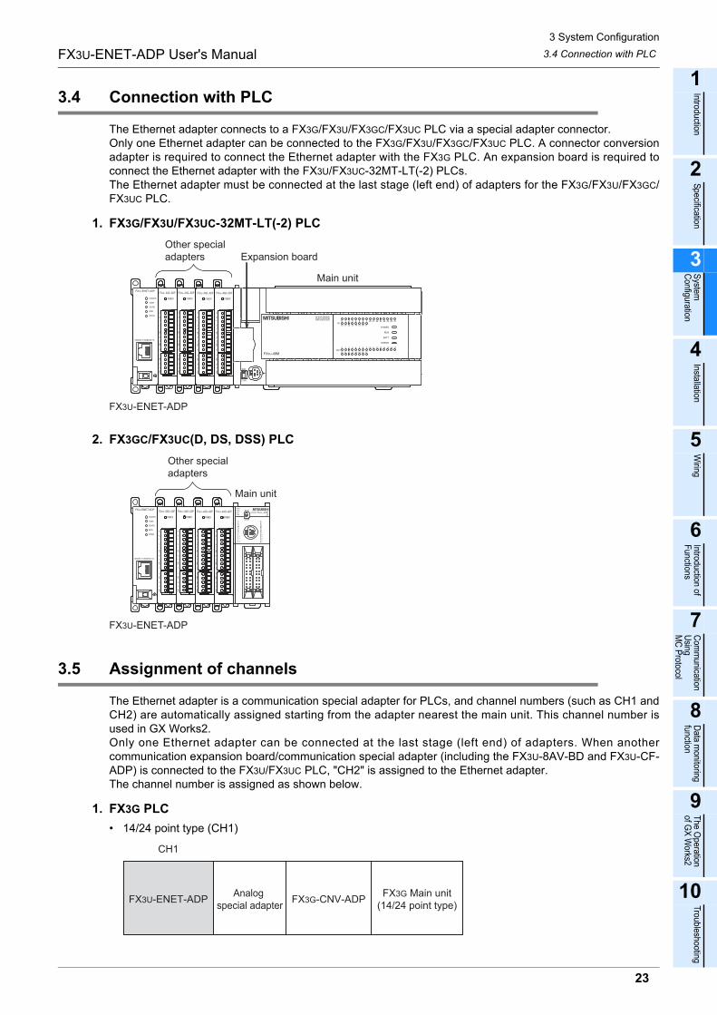
3.4 Connection with PLC
The Ethernet adapter connects to a FX3G/FX3U/FX3GC/FX3UC PLC via a special adapter connector.Only one Ethernet adapter can be connected to the FX3G/FX3U/FX3GC/FX3UC PLC. A connector conversionadapter is required to connect the Ethernet adapter with the FX3G PLC. An expansion board is required toconnect the Ethernet adapter with the FX3U/FX3UC-32MT-LT(-2) PLCs.The Ethernet adapter must be connected at the last stage (left end) of adapters for the FX3G/FX3U/FX3GC/FX3UC PLC.
1. FX3G/FX3U/FX3UC-32MT-LT(-2) PLC
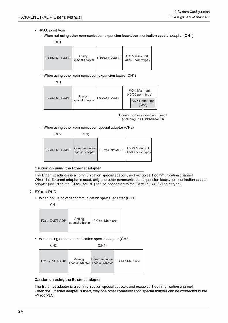
2. FX3GC/FX3UC(D, DS, DSS) PLC
3.5 Assignment of channels
The Ethernet adapter is a communication special adapter for PLCs, and channel numbers (such as CH1 andCH2) are automatically assigned starting from the adapter nearest the main unit. This channel number isused in GX Works2.Only one Ethernet adapter can be connected at the last stage (left end) of adapters. When anothercommunication expansion board/communication special adapter (including the FX3U-8AV-BD and FX3U-CF-ADP) is connected to the FX3U/FX3UC PLC, "CH2" is assigned to the Ethernet adapter.The channel number is assigned as shown below.
1. FX3G PLC
� 14/24 point type (CH1)
FX3U-ENET-ADP
Other special adapters Expansion board
Main unit
FX3U-ENET-ADP
Other special adapters
Main unit
FX3G Main unit(14/24 point type)
CH1
FX3U-ENET-ADPAnalog
special adapterFX3G-CNV-ADP
3 System Configuration
3.5 Assignment of channels
24
FX3U-ENET-ADP User's Manual
� 40/60 point type
- When not using other communication expansion board/communication special adapter (CH1)
- When using other communication expansion board (CH1)
- When using other communication special adapter (CH2)
Caution on using the Ethernet adapter
The Ethernet adapter is a communication special adapter, and occupies 1 communication channel.When the Ethernet adapter is used, only one other communication expansion board/communication special adapter (including the FX3G-8AV-BD) can be connected to the FX3G PLC(40/60 point type).
2. FX3GC PLC
� When not using other communication special adapter (CH1)
� When using other communication special adapter (CH2)
Caution on using the Ethernet adapter
The Ethernet adapter is a communication special adapter, and occupies 1 communication channel.When the Ethernet adapter is used, only one other communication special adapter can be connected to the FX3GC PLC.
FX3G Main unit(40/60 point type)
CH1
FX3U-ENET-ADPAnalog
special adapterFX3G-CNV-ADP
FX3G Main unit(40/60 point type)
Communication expansion board(including the FX3G-8AV-BD)
CH1
FX3U-ENET-ADPAnalog
special adapterFX3G-CNV-ADP
BD2 Connector(CH2)
FX3G Main unit(40/60 point type)
CH2 (CH1)
FX3U-ENET-ADPCommunicationspecial adapter
FX3G-CNV-ADP
FX3GC Main unit
CH1
FX3U-ENET-ADPAnalog
special adapter
FX3GC Main unit
CH2 (CH1)
FX3U-ENET-ADPAnalog
special adapterCommunication special adapter

3 System Configuration
3.5 Assignment of channels
25
FX3U-ENET-ADP User's Manual
1
Introduction
2
Specification
3
System
C
onfiguration
4
Installation
5
Wiring
6
Introduction of F
unctions
7
Com
munication
Using
MC
Protocol
8
Data m
onitoring function
9
The O
peration of G
X W
orks2
10
Troubleshooting
3. FX3U/FX3UC-32MT-LT(-2) PLC
� When not using other communication expansion board/communication special adapter (CH1)
� When using other communication expansion board/communication special adapter (CH2)
Caution on using the Ethernet adapter
The Ethernet adapter is a communication special adapter, and occupies 1 communication channel.When the Ethernet adapter is used, only one other communication expansion board/communication special adapter (including the FX3U-8AV-BD and FX3U-CF-ADP) can be connected to the FX3U/FX3UC-32MT-LT(-2) PLC.
4. FX3UC(D, DS, DSS) PLC
� When not using other communication special adapter (CH1)
� When using other communication special adapter (CH2)
Caution on using the Ethernet adapter
The Ethernet adapter is a communication special adapter, and occupies 1 communication channel.When the Ethernet adapter is used, only one other communication special adapter (including the FX3U-CF-ADP) can be connected to the FX3UC(D, DS, DSS) PLC.
FX3U, FX3UC-32MT-LT(-2)Main unit
CH1
FX3U-ENET-ADPAnalog
special adapterAnalog
special adapterFX3U-CNV-BD
FX3U, FX3UC-32MT-LT(-2)Main unit
CH2 (CH1)
FX3U-ENET-ADPAnalog
special adapter
Communication expansion
board
FX3UC(D, DS, DSS) Main unit
CH1
FX3U-ENET-ADPAnalog
special adapter
FX3UC(D, DS, DSS) Main unit
CH2 (CH1)
FX3U-ENET-ADPAnalog
special adapterAnalog
special adapterCommunication special adapter
4 Installation
26
FX3U-ENET-ADP User's Manual
4. Installation
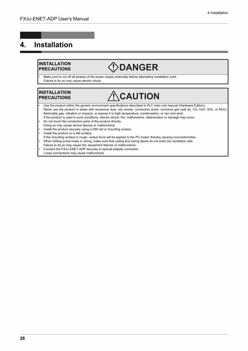
INSTALLATION PRECAUTIONS
� Make sure to cut off all phases of the power supply externally before attempting installation work.
Failure to do so may cause electric shock.
INSTALLATION PRECAUTIONS
� Use the product within the generic environment specifications described in PLC main unit manual (Hardware Edition).
Never use the product in areas with excessive dust, oily smoke, conductive dusts, corrosive gas (salt air, Cl2, H2S, SO2, or NO2),
flammable gas, vibration or impacts, or expose it to high temperature, condensation, or rain and wind.
If the product is used in such conditions, electric shock, fire, malfunctions, deterioration or damage may occur.
� Do not touch the conductive parts of the product directly.
Doing so may cause device failures or malfunctions.
� Install the product securely using a DIN rail or mounting screws.
� Install the product on a flat surface.
If the mounting surface is rough, undue force will be applied to the PC board, thereby causing nonconformities.
� When drilling screw holes or wiring, make sure that cutting and wiring debris do not enter the ventilation slits.
Failure to do so may cause fire, equipment failures or malfunctions.
� Connect the FX3U-ENET-ADP securely to special adapter connector.
Loose connections may cause malfunctions.
4 Installation
4.1 FX3U-ENET-ADP Connection
27
FX3U-ENET-ADP User's Manual
1
Introduction
2
Specification
3
System
C
onfiguration
4
Installation
5
Wiring
6
Introduction of F
unctions
7
Com
munication
Using
MC
Protocol
8
Data m
onitoring function
9
The O
peration of G
X W
orks2
10
Troubleshooting
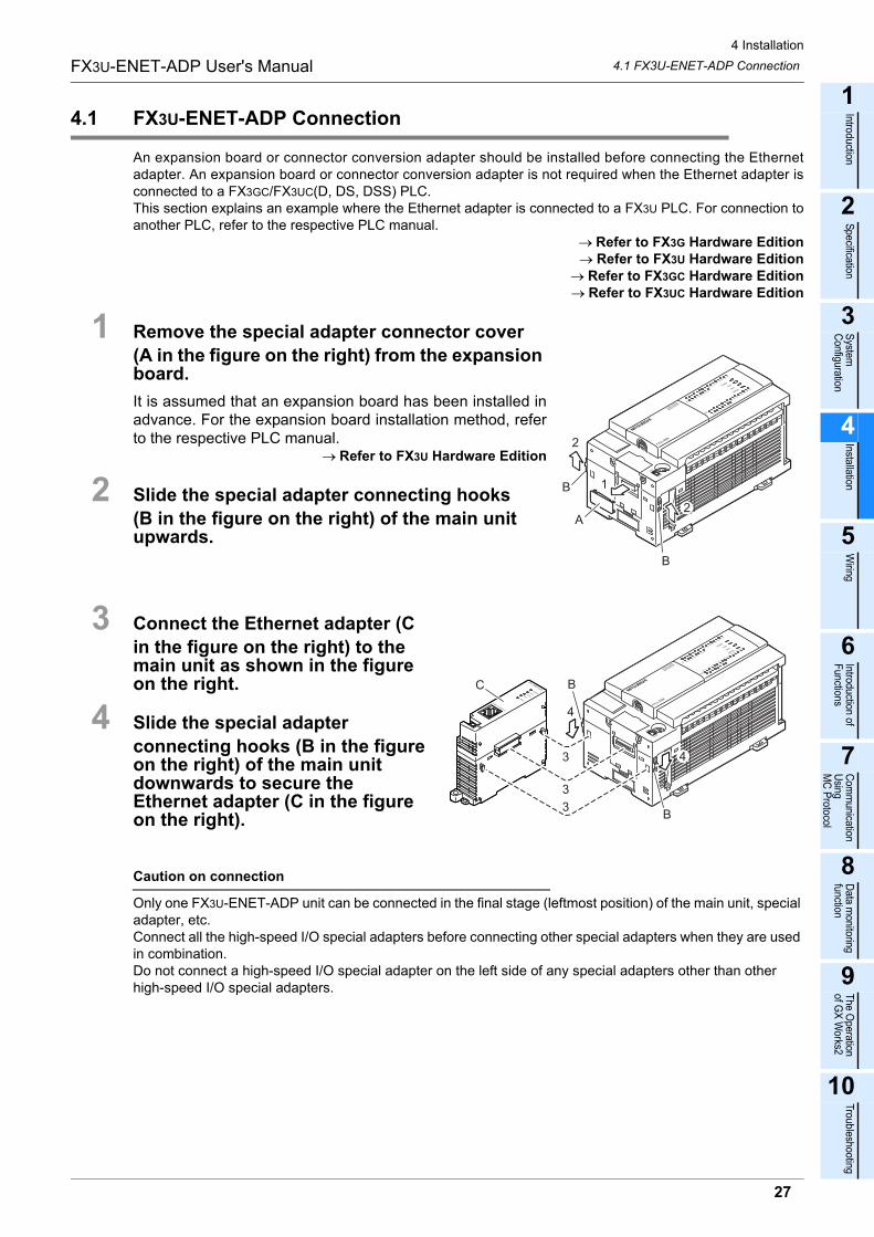
4.1 FX3U-ENET-ADP Connection
An expansion board or connector conversion adapter should be installed before connecting the Ethernetadapter. An expansion board or connector conversion adapter is not required when the Ethernet adapter isconnected to a FX3GC/FX3UC(D, DS, DSS) PLC.This section explains an example where the Ethernet adapter is connected to a FX3U PLC. For connection toanother PLC, refer to the respective PLC manual.
→ Refer to FX3G Hardware Edition→ Refer to FX3U Hardware Edition
→ Refer to FX3GC Hardware Edition→ Refer to FX3UC Hardware Edition
1 Remove the special adapter connector cover
(A in the figure on the right) from the expansion board.
It is assumed that an expansion board has been installed inadvance. For the expansion board installation method, referto the respective PLC manual.
→ Refer to FX3U Hardware Edition
2 Slide the special adapter connecting hooks
(B in the figure on the right) of the main unit upwards.
3 Connect the Ethernet adapter (C
in the figure on the right) to the main unit as shown in the figure on the right.
4 Slide the special adapter
connecting hooks (B in the figure on the right) of the main unit downwards to secure the Ethernet adapter (C in the figure on the right).
Caution on connection
Only one FX3U-ENET-ADP unit can be connected in the final stage (leftmost position) of the main unit, special adapter, etc. Connect all the high-speed I/O special adapters before connecting other special adapters when they are used in combination. Do not connect a high-speed I/O special adapter on the left side of any special adapters other than other high-speed I/O special adapters.
2
2
B
A
B 1
4
4
B
B
3
3
3
C
4 Installation
4.2 DIN rail mounting
28
FX3U-ENET-ADP User's Manual
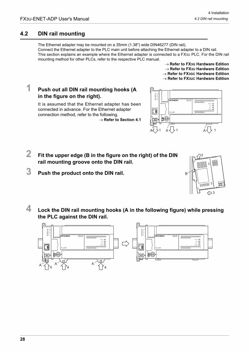
4.2 DIN rail mounting
The Ethernet adapter may be mounted on a 35mm (1.38") wide DIN46277 (DIN rail).Connect the Ethernet adapter to the PLC main unit before attaching the Ethernet adapter to a DIN rail.This section explains an example where the Ethernet adapter is connected to a FX3U PLC. For the DIN railmounting method for other PLCs, refer to the respective PLC manual.
→ Refer to FX3G Hardware Edition→ Refer to FX3U Hardware Edition
→ Refer to FX3GC Hardware Edition→ Refer to FX3UC Hardware Edition
1 Push out all DIN rail mounting hooks (A
in the figure on the right).
It is assumed that the Ethernet adapter has beenconnected in advance. For the Ethernet adapter connection method, refer to the following.
→ Refer to Section 4.1
2 Fit the upper edge (B in the figure on the right) of the DIN
rail mounting groove onto the DIN rail.
3 Push the product onto the DIN rail.
4 Lock the DIN rail mounting hooks (A in the following figure) while pressing
the PLC against the DIN rail.
111A A A
2
B
3
A44 4
AA
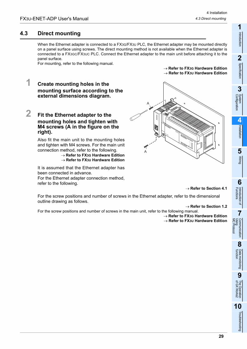
4 Installation
4.3 Direct mounting
29
FX3U-ENET-ADP User's Manual
1
Introduction
2
Specification
3
System
C
onfiguration
4
Installation
5
Wiring
6
Introduction of F
unctions
7
Com
munication
Using
MC
Protocol
8
Data m
onitoring function
9
The O
peration of G
X W
orks2
10
Troubleshooting
4.3 Direct mounting
When the Ethernet adapter is connected to a FX3G/FX3U PLC, the Ethernet adapter may be mounted directlyon a panel surface using screws. The direct mounting method is not available when the Ethernet adapter isconnected to a FX3GC/FX3UC PLC. Connect the Ethernet adapter to the main unit before attaching it to thepanel surface.For mounting, refer to the following manual.
→ Refer to FX3G Hardware Edition→ Refer to FX3U Hardware Edition
1 Create mounting holes in the
mounting surface according to the external dimensions diagram.
2 Fit the Ethernet adapter to the
mounting holes and tighten with M4 screws (A in the figure on the right).
Also fit the main unit to the mounting holesand tighten with M4 screws. For the main unitconnection method, refer to the following.
→ Refer to FX3G Hardware Edition→ Refer to FX3U Hardware Edition
It is assumed that the Ethernet adapter hasbeen connected in advance. For the Ethernet adapter connection method,refer to the following.
→ Refer to Section 4.1
For the screw positions and number of screws in the Ethernet adapter, refer to the dimensional outline drawing as follows.
→ Refer to Section 1.2For the screw positions and number of screws in the main unit, refer to the following manual.
→ Refer to FX3G Hardware Edition→ Refer to FX3U Hardware Edition
A
A
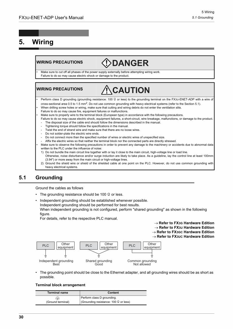
5 Wiring
5.1 Grounding
30
FX3U-ENET-ADP User's Manual
5. Wiring
5.1 Grounding
Ground the cables as follows
� The grounding resistance should be 100 or less.
� Independent grounding should be established whenever possible.Independent grounding should be performed for best results.When independent grounding is not configured, perform "shared grounding" as shown in the following figure.For details, refer to the respective PLC manual.
→ Refer to FX3G Hardware Edition→ Refer to FX3U Hardware Edition
→ Refer to FX3GC Hardware Edition→ Refer to FX3UC Hardware Edition
� The grounding point should be close to the Ethernet adapter, and all grounding wires should be as short as possible.
Terminal block arrangement
WIRING PRECAUTIONS
� Make sure to cut off all phases of the power supply externally before attempting wiring work.
Failure to do so may cause electric shock or damage to the product.
WIRING PRECAUTIONS
� Perform class D grounding (grounding resistance: 100 or less) to the grounding terminal on the FX3U-ENET-ADP with a wire of
cross-sectional area 0.5 to 1.5 mm2. Do not use common grounding with heavy electrical systems (refer to the Section 5.1).
� When drilling screw holes or wiring, make sure that cutting and wiring debris do not enter the ventilation slits.
Failure to do so may cause fire, equipment failures or malfunctions.
� Make sure to properly wire to the terminal block (European type) in accordance with the following precautions.
Failure to do so may cause electric shock, equipment failures, a short-circuit, wire breakage, malfunctions, or damage to the product.
- The disposal size of the cable end should follow the dimensions described in the manual.
- Tightening torque should follow the specifications in the manual.
- Twist the end of strand wire and make sure that there are no loose wires.
- Do not solder-plate the electric wire ends.
- Do not connect more than the specified number of wires or electric wires of unspecified size.
- Affix the electric wires so that neither the terminal block nor the connected parts are directly stressed.
� Make sure to observe the following precautions in order to prevent any damage to the machinery or accidents due to abnormal data
written to the PLC under the influence of noise:
1) Do not bundle the main circuit line together with or lay it close to the main circuit, high-voltage line or load line.
Otherwise, noise disturbance and/or surge induction are likely to take place. As a guideline, lay the control line at least 100mm
(3.94") or more away from the main circuit or high-voltage lines.
2) Ground the shield wire or shield of the shielded cable at one point on the PLC. However, do not use common grounding with
heavy electrical systems.
Terminal name Content
(Ground terminal)
Perform class D grounding.
(Grounding resistance: 100 or less)
PLC Otherequipment
Shared groundingGood
Common groundingNot allowed
Independent groundingBest
PLC Otherequipment
PLC Otherequipment
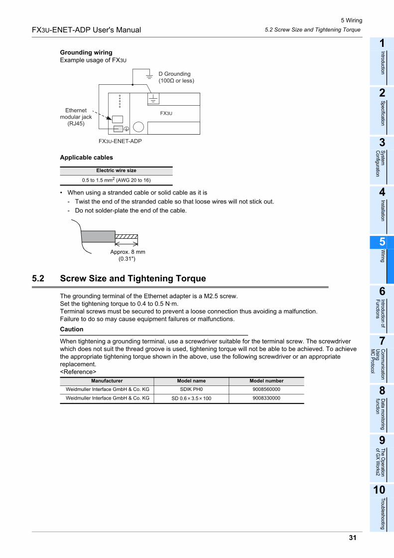
5 Wiring
5.2 Screw Size and Tightening Torque
31
FX3U-ENET-ADP User's Manual
1
Introduction
2
Specification
3
System
C
onfiguration
4
Installation
5
Wiring
6
Introduction of F
unctions
7
Com
munication
Using
MC
Protocol
8
Data m
onitoring function
9
The O
peration of G
X W
orks2
10
Troubleshooting
Grounding wiringExample usage of FX3U
Applicable cables
� When using a stranded cable or solid cable as it is
- Twist the end of the stranded cable so that loose wires will not stick out.
- Do not solder-plate the end of the cable.
5.2 Screw Size and Tightening Torque
The grounding terminal of the Ethernet adapter is a M2.5 screw.Set the tightening torque to 0.4 to 0.5 N·m.Terminal screws must be secured to prevent a loose connection thus avoiding a malfunction.Failure to do so may cause equipment failures or malfunctions.
Caution
When tightening a grounding terminal, use a screwdriver suitable for the terminal screw. The screwdriver which does not suit the thread groove is used, tightening torque will not be able to be achieved. To achieve the appropriate tightening torque shown in the above, use the following screwdriver or an appropriate replacement.<Reference>
Electric wire size
0.5 to 1.5 mm2 (AWG 20 to 16)
Manufacturer Model name Model number
Weidmuller Interface GmbH & Co. KG SDIK PH0 9008560000
Weidmuller Interface GmbH & Co. KG SD 0.6 3.5 100 9008330000
FX3U-ENET-ADP
D Grounding(100Ω or less)
FX3UEthernet
modular jack(RJ45)
Approx. 8 mm(0.31")
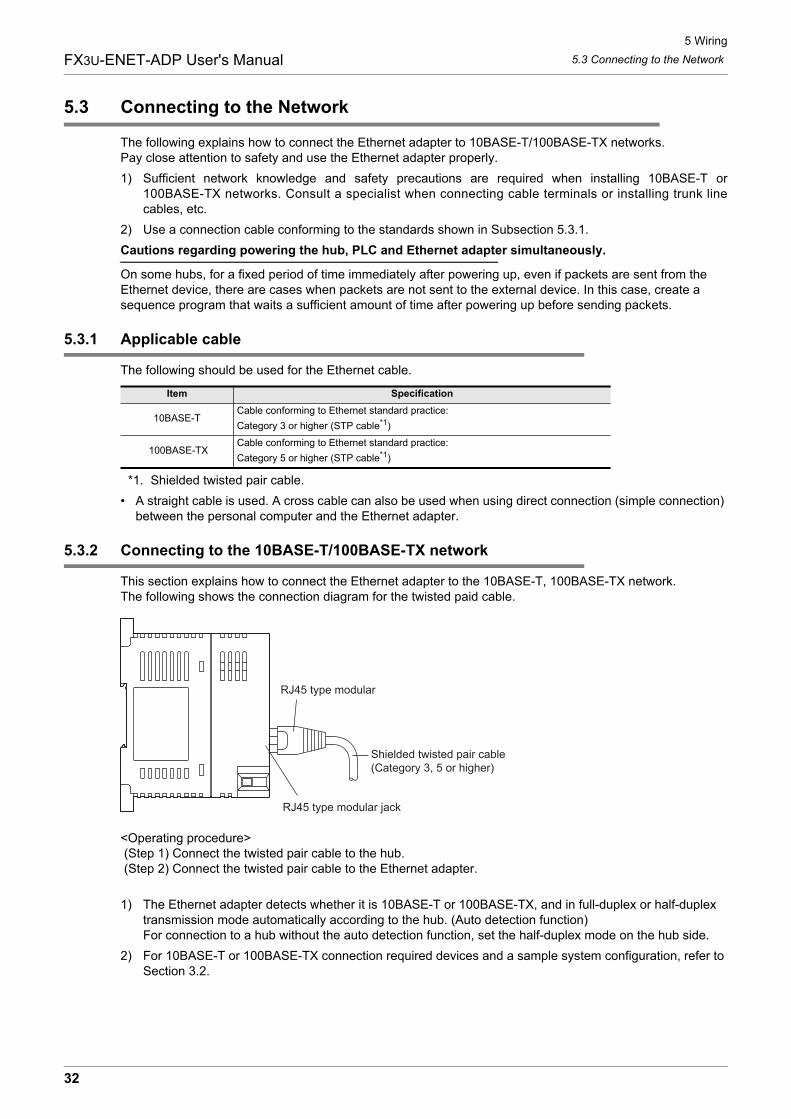
5 Wiring
5.3 Connecting to the Network
32
FX3U-ENET-ADP User's Manual
5.3 Connecting to the Network
The following explains how to connect the Ethernet adapter to 10BASE-T/100BASE-TX networks.Pay close attention to safety and use the Ethernet adapter properly.
1) Sufficient network knowledge and safety precautions are required when installing 10BASE-T or100BASE-TX networks. Consult a specialist when connecting cable terminals or installing trunk linecables, etc.
2) Use a connection cable conforming to the standards shown in Subsection 5.3.1.
Cautions regarding powering the hub, PLC and Ethernet adapter simultaneously.
On some hubs, for a fixed period of time immediately after powering up, even if packets are sent from the Ethernet device, there are cases when packets are not sent to the external device. In this case, create a sequence program that waits a sufficient amount of time after powering up before sending packets.
5.3.1 Applicable cable
The following should be used for the Ethernet cable.
*1. Shielded twisted pair cable.
� A straight cable is used. A cross cable can also be used when using direct connection (simple connection) between the personal computer and the Ethernet adapter.
5.3.2 Connecting to the 10BASE-T/100BASE-TX network
This section explains how to connect the Ethernet adapter to the 10BASE-T, 100BASE-TX network.The following shows the connection diagram for the twisted paid cable.
<Operating procedure> (Step 1) Connect the twisted pair cable to the hub. (Step 2) Connect the twisted pair cable to the Ethernet adapter.
1) The Ethernet adapter detects whether it is 10BASE-T or 100BASE-TX, and in full-duplex or half-duplex transmission mode automatically according to the hub. (Auto detection function) For connection to a hub without the auto detection function, set the half-duplex mode on the hub side.
2) For 10BASE-T or 100BASE-TX connection required devices and a sample system configuration, refer to Section 3.2.
Item Specification
10BASE-TCable conforming to Ethernet standard practice:
Category 3 or higher (STP cable*1)
100BASE-TXCable conforming to Ethernet standard practice:
Category 5 or higher (STP cable*1)
RJ45 type modular
RJ45 type modular jack
Shielded twisted pair cable (Category 3, 5 or higher)
6 Introduction of Functions
33
FX3U-ENET-ADP User's Manual
1
Introduction
2
Specification
3
System
C
onfiguration
4
Installation
5
Wiring
6
Introduction of F
unctions
7
Com
munication
Using
MC
Protocol
8
Data m
onitoring function
9
The O
peration of G
X W
orks2
10
Troubleshooting
6.1 Functions List
6. Introduction of Functions
6.1 Functions List
This section shows a list of Ethernet adapter functions.
6.2 Details of functions
6.2.1 MELSOFT connections
This function allows communication with a MELSOFT product (such as GX Work2) in the LAN (such ascompany LAN).This function is equivalent to the communication function supported on the RS-422 port in the PLC main unit,and provides the following:
� Reading, writing (including writing during RUN) and verification of programs
� Reading and test of devices in the PLC main unit (including buffer memories in special function blocks)
This function is activated when the open method of the connection No. used for the open setting is set to"MELSOFT connections".For operation of GX Works2, refer to Section 9.2.
6.2.2 Communication Using MC Protocol
For details of MC Protocol, refer to Chapter 7.
Functions Description Reference section
MELSOFT connectionsThis function allows communication with a MELSOFT product (such as GX Work2)
on a LAN (such as company LAN).Subsection 6.2.1
Communication Using MC
Protocol
This function reads/writes the PLC data from/to an external device, and supports
subsets of the A-compatible 1E frame.Chapter 7
MELSOFT Direct Connection
(Simple Connection)
This function connects the Ethernet adapter attached to the main unit to a MELSOFT
product (such as GX Works2) with one Ethernet cable without using a hub, and
enables communication when only the connection destination is specified. It is not
necessary to set the IP address.
Subsection 6.2.3
Find CPU function
This function searches (PLC CPUs connected to) Ethernet adapters connected to
the same hub as the personal computer using GX Works2, and enables selection of
a desired CPU from the list of found CPUs and acquisition of the IP address.
Subsection 6.2.4
Time setting functionThis function accesses the time information server (SNTP server) connected to the
LAN, collects the time information, and automatically sets the time to the main unit.Subsection 6.2.5
Parameter setting functionThis function sets parameters of the Ethernet adapter from GX Works2 via the main
unit.Subsection 6.2.6
Diagnostics function from
MELSOFT
This function diagnoses the Ethernet adapter from GX Works2 via the main unit.
(Ethernet Diagnostics)Subsection 6.2.7
Data monitoring functionThis function monitors the information on the PLC main unit, device values and
Ethernet adapter from the browser in the personal computer.Chapter 8
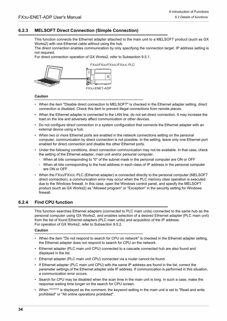
6 Introduction of Functions
34
FX3U-ENET-ADP User's Manual 6.2 Details of functions
6.2.3 MELSOFT Direct Connection (Simple Connection)
This function connects the Ethernet adapter attached to the main unit to a MELSOFT product (such as GXWorks2) with one Ethernet cable without using the hub.The direct connection enables communication by only specifying the connection target. IP address setting isnot required.For direct connection operation of GX Works2, refer to Subsection 9.5.1.
Caution
� When the item "Disable direct connection to MELSOFT" is checked in the Ethernet adapter setting, direct connection is disabled. Check this item to prevent illegal connections from remote places.
� When the Ethernet adapter is connected to the LAN line, do not set direct connection. It may increase the load on the line and adversely affect communication or other devices.
� Do not configure direct connection in a system configuration that connects the Ethernet adapter with an external device using a hub.
� When two or more Ethernet ports are enabled in the network connections setting on the personal computer, communication by direct connection is not possible. In the setting, leave only one Ethernet port enabled for direct connection and disable the other Ethernet ports.
� Under the following conditions, direct connection communication may not be available. In that case, check the setting of the Ethernet adapter, main unit and/or personal computer.
- When all bits corresponding to "0" of the subnet mask in the personal computer are ON or OFF
- When all bits corresponding to the host address in each class of IP address in the personal computer are ON or OFF
� When the FX3G/FX3GC PLC (Ethernet adapter) is connected directly to the personal computer (MELSOFT direct connection), a communication error may occur when the PLC memory clear operation is executed due to the Windows firewall. In this case, open the Windows control panel, and specify the MELSOFT product (such as GX Works2) as "Allowed program" or "Exception" in the security setting for Windows firewall.
6.2.4 Find CPU function
This function searches Ethernet adapters (connected to PLC main units) connected to the same hub as thepersonal computer using GX Works2, and enables selection of a desired Ethernet adapter (PLC main unit)from the list of found Ethernet adapters (PLC main units) and acquisition of the IP address.For operation of GX Works2, refer to Subsection 9.5.2.
Caution
� When the item "Do not respond to search for CPU on network" is checked in the Ethernet adapter setting, the Ethernet adapter does not respond to search for CPU on the network.
� Ethernet adapter (PLC main unit CPU) connected to a cascade connected hub are also found and displayed in the list.
� Ethernet adapter (PLC main unit CPU) connected via a router cannot be found.
� If Ethernet adapter (PLC main unit CPU) with the same IP address are found in the list, correct the parameter settings of the Ethernet adapter side IP address. If communication is performed in this situation, a communication error occurs.
� Search for CPU may be disabled when the scan time in the main unit is long. In such a case, make the response waiting time longer on the search for CPU screen.
� When "*****" is displayed as the comment, the keyword setting in the main unit is set to "Read and write prohibited" or "All online operations prohibited".
FX3G/FX3U/FX3GC/FX3UC PLC
FX3U-ENET-ADP
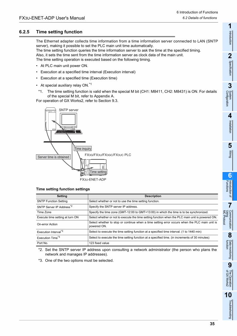
6 Introduction of Functions
35
FX3U-ENET-ADP User's Manual
1
Introduction
2
Specification
3
System
C
onfiguration
4
Installation
5
Wiring
6
Introduction of F
unctions
7
Com
munication
Using
MC
Protocol
8
Data m
onitoring function
9
The O
peration of G
X W
orks2
10
Troubleshooting
6.2 Details of functions
6.2.5 Time setting function
The Ethernet adapter collects time information from a time information server connected to LAN (SNTPserver), making it possible to set the PLC main unit time automatically.The time setting function queries the time information server to ask the time at the specified timing.Also, it sets the time sent from the time information server as clock data of the main unit.The time setting operation is executed based on the following timing.
� At PLC main unit power ON.
� Execution at a specified time interval (Execution interval)
� Execution at a specified time (Execution time)
� At special auxiliary relay ON.*1
*1. The time setting function is valid when the special M bit (CH1: M8411, CH2: M8431) is ON. For detailsof the special M bit, refer to Appendix A.
For operation of GX Works2, refer to Section 9.3.
Time setting function settings
*2. Set the SNTP server IP address upon consulting a network administrator (the person who plans thenetwork and manages IP addresses).
*3. One of the two options must be selected.
Setting Description
SNTP Function Setting Select whether or not to use the time setting function.
SNTP Server IP Address*2 Specify the SNTP server IP address.
Time Zone Specify the time zone (GMT-12:00 to GMT+13:00) in which the time is to be synchronized.
Execute time setting at turn ON Select whether or not to execute the time setting function when the PLC main unit is powered ON.
On-error ActionSelect whether to stop or continue when a time setting error occurs when the PLC main unit is
powered ON.
Execution Interval*3 Select to execute the time setting function at a specified time interval. (1 to 1440 min)
Execution Time*3 Select to execute the time setting function at a specified time. (in increments of 30 minutes)
Port No. 123 fixed value
FX3G/FX3U/FX3GC/FX3UC PLC
FX3U-ENET-ADP
SNTP server
Server time is obtained
Time inquiry
Time setting
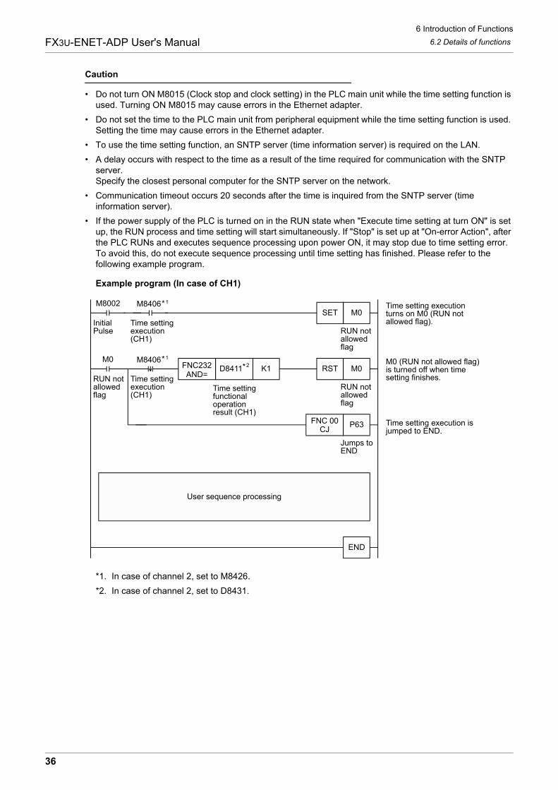
6 Introduction of Functions
36
FX3U-ENET-ADP User's Manual 6.2 Details of functions
Caution
� Do not turn ON M8015 (Clock stop and clock setting) in the PLC main unit while the time setting function is used. Turning ON M8015 may cause errors in the Ethernet adapter.
� Do not set the time to the PLC main unit from peripheral equipment while the time setting function is used. Setting the time may cause errors in the Ethernet adapter.
� To use the time setting function, an SNTP server (time information server) is required on the LAN.
� A delay occurs with respect to the time as a result of the time required for communication with the SNTP server.Specify the closest personal computer for the SNTP server on the network.
� Communication timeout occurs 20 seconds after the time is inquired from the SNTP server (time information server).
� If the power supply of the PLC is turned on in the RUN state when "Execute time setting at turn ON" is set up, the RUN process and time setting will start simultaneously. If "Stop" is set up at "On-error Action", after the PLC RUNs and executes sequence processing upon power ON, it may stop due to time setting error. To avoid this, do not execute sequence processing until time setting has finished. Please refer to the following example program.
Example program (In case of CH1)
*1. In case of channel 2, set to M8426.
*2. In case of channel 2, set to D8431.
M8002 Time setting executionturns on M0 (RUN notallowed flag).
M8406*1
*1
InitialPulse
Time settingexecution(CH1)
M0SET
FNC232AND=
D8411 K1M0
RUN notallowedflag
M8406RST M0
FNC 00CJ
P63
Jumps toEND
Time settingfunctionaloperationresult (CH1)
M0 (RUN not allowed flag)is turned off when time setting finishes.
Time setting execution isjumped to END.
User sequence processing
END
Time settingexecution(CH1)
RUN notallowedflag
RUN notallowedflag
*2
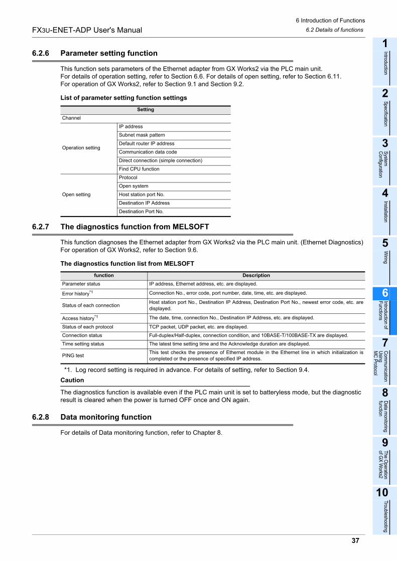
6 Introduction of Functions
37
FX3U-ENET-ADP User's Manual
1
Introduction
2
Specification
3
System
C
onfiguration
4
Installation
5
Wiring
6
Introduction of F
unctions
7
Com
munication
Using
MC
Protocol
8
Data m
onitoring function
9
The O
peration of G
X W
orks2
10
Troubleshooting
6.2 Details of functions
6.2.6 Parameter setting function
This function sets parameters of the Ethernet adapter from GX Works2 via the PLC main unit.For details of operation setting, refer to Section 6.6. For details of open setting, refer to Section 6.11.For operation of GX Works2, refer to Section 9.1 and Section 9.2.
List of parameter setting function settings
6.2.7 The diagnostics function from MELSOFT
This function diagnoses the Ethernet adapter from GX Works2 via the PLC main unit. (Ethernet Diagnostics)For operation of GX Works2, refer to Section 9.6.
The diagnostics function list from MELSOFT
*1. Log record setting is required in advance. For details of setting, refer to Section 9.4.
Caution
The diagnostics function is available even if the PLC main unit is set to batteryless mode, but the diagnostic result is cleared when the power is turned OFF once and ON again.
6.2.8 Data monitoring function
For details of Data monitoring function, refer to Chapter 8.
Setting
Channel
Operation setting
IP address
Subnet mask pattern
Default router IP address
Communication data code
Direct connection (simple connection)
Find CPU function
Open setting
Protocol
Open system
Host station port No.
Destination IP Address
Destination Port No.
function Description
Parameter status IP address, Ethernet address, etc. are displayed.
Error history*1 Connection No., error code, port number, date, time, etc. are displayed.
Status of each connectionHost station port No., Destination IP Address, Destination Port No., newest error code, etc. are
displayed.
Access history*1 The date, time, connection No., Destination IP Address, etc. are displayed.
Status of each protocol TCP packet, UDP packet, etc. are displayed.
Connection status Full-duplex/Half-duplex, connection condition, and 10BASE-T/100BASE-TX are displayed.
Time setting status The latest time setting time and the Acknowledge duration are displayed.
PING testThis test checks the presence of Ethernet module in the Ethernet line in which initialization is
completed or the presence of specified IP address.
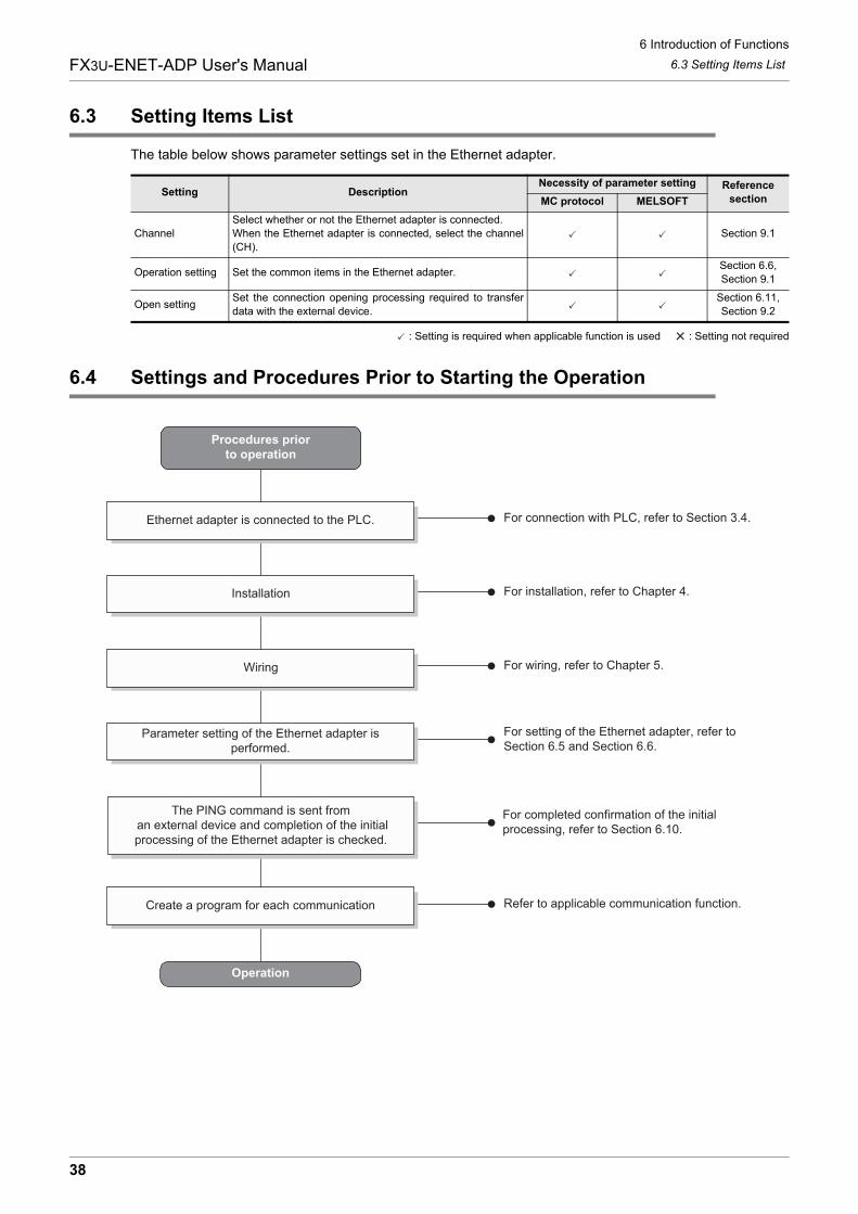
6 Introduction of Functions
38
FX3U-ENET-ADP User's Manual 6.3 Setting Items List
6.3 Setting Items List
The table below shows parameter settings set in the Ethernet adapter.
: Setting is required when applicable function is used : Setting not required
6.4 Settings and Procedures Prior to Starting the Operation
Setting DescriptionNecessity of parameter setting Reference
sectionMC protocol MELSOFT
Channel
Select whether or not the Ethernet adapter is connected.
When the Ethernet adapter is connected, select the channel
(CH).
Section 9.1
Operation setting Set the common items in the Ethernet adapter.Section 6.6,
Section 9.1
Open settingSet the connection opening processing required to transfer
data with the external device.
Section 6.11,
Section 9.2
Procedures priorto operation
Operation
Parameter setting of the Ethernet adapter isperformed.
For setting of the Ethernet adapter, refer toSection 6.5 and Section 6.6.
Wiring For wiring, refer to Chapter 5.
For installation, refer to Chapter 4.Installation
For connection with PLC, refer to Section 3.4.Ethernet adapter is connected to the PLC.
The PING command is sent from an external device and completion of the initialprocessing of the Ethernet adapter is checked.
For completed confirmation of the initialprocessing, refer to Section 6.10.
Create a program for each communication Refer to applicable communication function.
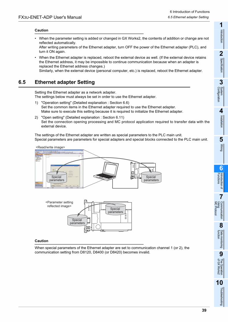
6 Introduction of Functions
39
FX3U-ENET-ADP User's Manual
1
Introduction
2
Specification
3
System
C
onfiguration
4
Installation
5
Wiring
6
Introduction of F
unctions
7
Com
munication
Using
MC
Protocol
8
Data m
onitoring function
9
The O
peration of G
X W
orks2
10
Troubleshooting
6.5 Ethernet adapter Setting
Caution
� When the parameter setting is added or changed in GX Works2, the contents of addition or change are not reflected automatically. After writing parameters of the Ethernet adapter, turn OFF the power of the Ethernet adapter (PLC), and turn it ON again.
� When the Ethernet adapter is replaced, reboot the external device as well. (If the external device retains the Ethernet address, it may be impossible to continue communication because when an adapter is replaced the Ethernet address changes.)Similarly, when the external device (personal computer, etc.) is replaced, reboot the Ethernet adapter.
6.5 Ethernet adapter Setting
Setting the Ethernet adapter as a network adapter.The settings below must always be set in order to use the Ethernet adapter.
1) "Operation setting" (Detailed explanation : Section 6.6)Set the common items in the Ethernet adapter required to use the Ethernet adapter.Make sure to execute this setting because it is required to initialize the Ethernet adapter.
2) "Open setting" (Detailed explanation : Section 6.11)Set the connection opening processing and MC protocol application required to transfer data with theexternal device.
The settings of the Ethernet adapter are written as special parameters to the PLC main unit.Special parameters are parameters for special adapters and special blocks connected to the PLC main unit.
Caution
When special parameters of the Ethernet adapter are set to communication channel 1 (or 2), the communication setting from D8120, D8400 (or D8420) becomes invalid.
Special parameters
<Read/write image>
<Parameter setting reflected image>
Special parameters
Special parameters
Special parameters
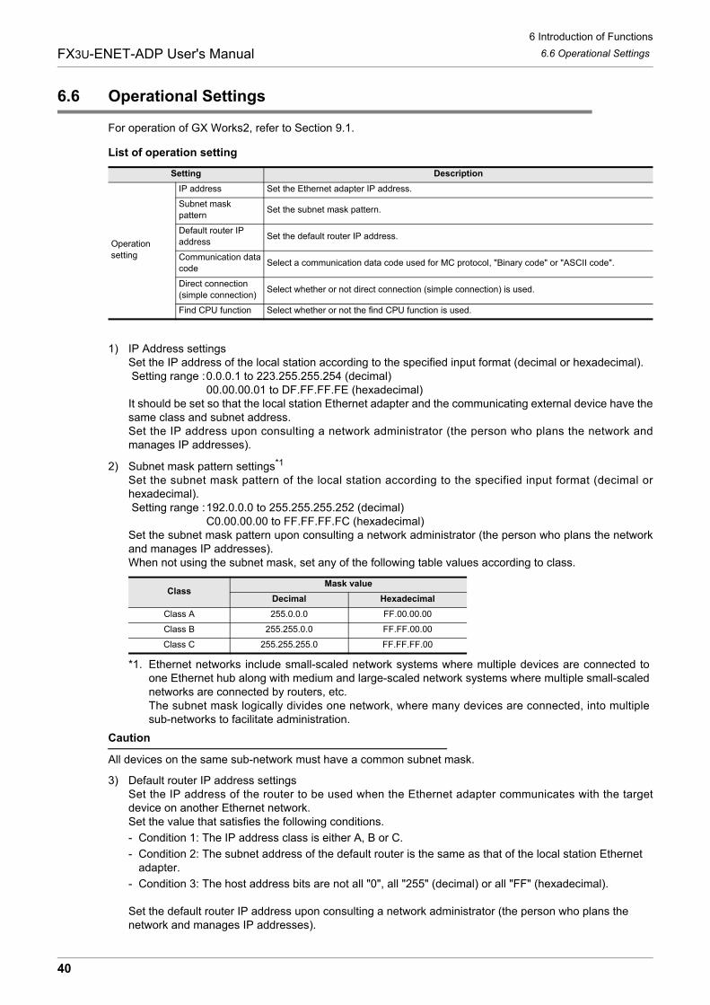
6 Introduction of Functions
40
FX3U-ENET-ADP User's Manual 6.6 Operational Settings
6.6 Operational Settings
For operation of GX Works2, refer to Section 9.1.
List of operation setting
1) IP Address settingsSet the IP address of the local station according to the specified input format (decimal or hexadecimal). Setting range :0.0.0.1 to 223.255.255.254 (decimal)
00.00.00.01 to DF.FF.FF.FE (hexadecimal)It should be set so that the local station Ethernet adapter and the communicating external device have thesame class and subnet address.Set the IP address upon consulting a network administrator (the person who plans the network andmanages IP addresses).
2) Subnet mask pattern settings*1
Set the subnet mask pattern of the local station according to the specified input format (decimal orhexadecimal). Setting range :192.0.0.0 to 255.255.255.252 (decimal)
C0.00.00.00 to FF.FF.FF.FC (hexadecimal)Set the subnet mask pattern upon consulting a network administrator (the person who plans the networkand manages IP addresses).When not using the subnet mask, set any of the following table values according to class.
*1. Ethernet networks include small-scaled network systems where multiple devices are connected toone Ethernet hub along with medium and large-scaled network systems where multiple small-scalednetworks are connected by routers, etc. The subnet mask logically divides one network, where many devices are connected, into multiplesub-networks to facilitate administration.
Caution
All devices on the same sub-network must have a common subnet mask.
3) Default router IP address settingsSet the IP address of the router to be used when the Ethernet adapter communicates with the targetdevice on another Ethernet network.Set the value that satisfies the following conditions.
- Condition 1: The IP address class is either A, B or C.
- Condition 2: The subnet address of the default router is the same as that of the local station Ethernet adapter.
- Condition 3: The host address bits are not all "0", all "255" (decimal) or all "FF" (hexadecimal).
Set the default router IP address upon consulting a network administrator (the person who plans the network and manages IP addresses).
Setting Description
Operation
setting
IP address Set the Ethernet adapter IP address.
Subnet mask
patternSet the subnet mask pattern.
Default router IP
addressSet the default router IP address.
Communication data
codeSelect a communication data code used for MC protocol, "Binary code" or "ASCII code".
Direct connection
(simple connection)Select whether or not direct connection (simple connection) is used.
Find CPU function Select whether or not the find CPU function is used.
ClassMask value
Decimal Hexadecimal
Class A 255.0.0.0 FF.00.00.00
Class B 255.255.0.0 FF.FF.00.00
Class C 255.255.255.0 FF.FF.FF.00
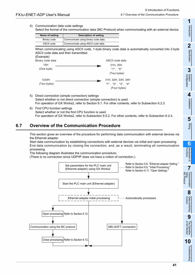
6 Introduction of Functions
41
FX3U-ENET-ADP User's Manual
1
Introduction
2
Specification
3
System
C
onfiguration
4
Installation
5
Wiring
6
Introduction of F
unctions
7
Com
munication
Using
MC
Protocol
8
Data m
onitoring function
9
The O
peration of G
X W
orks2
10
Troubleshooting
6.7 Overview of the Communication Procedure
4) Communication data code settingsSelect the format of the communication data (MC Protocol) when communicating with an external device.
When communicating using ASCII code, 1-byte binary code data is automatically converted into 2-byteASCII code data and then transmitted.(Example)
5) Direct connection (simple connection) settingsSelect whether or not direct connection (simple connection) is used.For operation of GX Works2, refer to Section 9.1. For other contents, refer to Subsection 6.2.3.
6) Find CPU function settingsSelect whether or not the find CPU function is used.For operation of GX Works2, refer to Subsection 9.5.2. For other contents, refer to Subsection 6.2.4.
6.7 Overview of the Communication Procedure
This section gives an overview of the procedure for performing data communication with external devices viathe Ethernet adapter.Start data communication by establishing connections with external devices via initial and open processing.End data communication by closing the connection, and, as a result, terminating all communicationprocessing.The following diagram illustrates the communication procedure:(There is no connection since UDP/IP does not have a notion of connection.)
Name of setting Description of setting
Binary code Communicate using binary code data.
ASCII code Communicate using ASCII code data.
Binary code data
15H
(One byte)
ASCII code data
31H, 35H
(Two bytes)
(Four bytes)
"1" , "5"
1234H
(Two bytes) "4""3" ,"2" ,"1" ,
31H, 32H, 33H, 34H
Set parameters for the PLC main unit (Ethernet adapter) using GX Works2
Start the PLC main unit (Ethernet adapter)
Ethernet adapter initial processing
Open processing
Communication using the MC protocol
Close processing
MELSOFT connection
Automatically processed.
Refer to Section 6.6, "Ethernet adapter Setting."Refer to Section 6.8, "Initial Processing."Refer to Section 6.11, "Open Settings."
Refer to Section 6.12.
Refer to Section 6.12.
6 Introduction of Functions
42
FX3U-ENET-ADP User's Manual 6.8 Initial Processing
6.8 Initial Processing
This section explains the initial processing of the Ethernet adapter.
6.8.1 Initial processing
Initial processing enables data communication with an external device by setting the parameters required fordata communication via the Ethernet adapter.The Ethernet adapter automatically executes initial processing based on parameters set in GX Works2.When parameters are set in GX Works2 and then the power of the Ethernet adapter (PLC) is turned OFF andON, initial processing is executed.
6.8.2 Initial settings
The Ethernet adapter automatically executes initial processing based on parameters set in GX Works2.You do not have to write the initial settings.
6.8.3 Re-initialization
Re-initialization (which sets the Ethernet adapter to the status at startup without turning OFF and ON thepower of the PLC) is not available in the Ethernet adapter.After setting parameters in GX Works2, turn OFF and ON the power of the Ethernet adapter (PLC).
6.9 Router Relay Parameter
Ethernet adapter access from the company LAN, etc. via a router are enabled when the subnet mask patternand default router IP address are set in the operation setting.
6.10 Confirming Completion of Initial Processing
The initial processing of the Ethernet adapter is completed when the power of the PLC main unit is turnedOFF and ON after parameters are written to the PLC main unit.This section explains how to check for completion of initial processing.
Caution
Ethernet adapter communication is enabled when initial processing is completed normally. See reference sections for each communication function to work.When initial processing has not been completed normally, do the following: check the error contents, take corrective actions, then execute the initial processing again.
� Check the error code using the "Parameter status" of Ethernet diagnostics. (Refer to Section 9.6 and Subsection 10.2.1.)
� Check the contents of the error corresponding to the error code, then take corrective actions. (Refer to Subsection 10.3.1.)
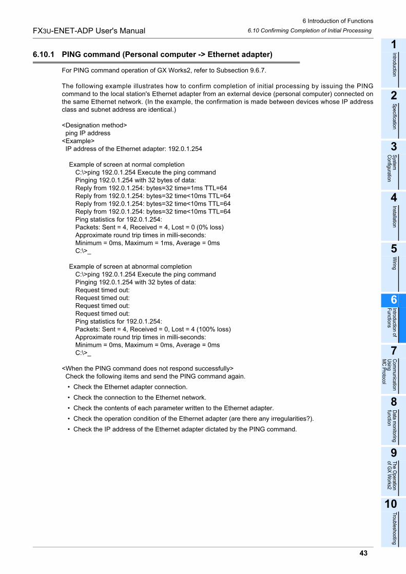
6 Introduction of Functions
43
FX3U-ENET-ADP User's Manual
1
Introduction
2
Specification
3
System
C
onfiguration
4
Installation
5
Wiring
6
Introduction of F
unctions
7
Com
munication
Using
MC
Protocol
8
Data m
onitoring function
9
The O
peration of G
X W
orks2
10
Troubleshooting
6.10 Confirming Completion of Initial Processing
6.10.1 PING command (Personal computer -> Ethernet adapter)
For PING command operation of GX Works2, refer to Subsection 9.6.7.
The following example illustrates how to confirm completion of initial processing by issuing the PINGcommand to the local station's Ethernet adapter from an external device (personal computer) connected onthe same Ethernet network. (In the example, the confirmation is made between devices whose IP addressclass and subnet address are identical.)
<Designation method> ping IP address<Example> IP address of the Ethernet adapter: 192.0.1.254
Example of screen at normal completionC:\>ping 192.0.1.254 Execute the ping commandPinging 192.0.1.254 with 32 bytes of data:Reply from 192.0.1.254: bytes=32 time=1ms TTL=64Reply from 192.0.1.254: bytes=32 time<10ms TTL=64Reply from 192.0.1.254: bytes=32 time<10ms TTL=64Reply from 192.0.1.254: bytes=32 time<10ms TTL=64Ping statistics for 192.0.1.254:Packets: Sent = 4, Received = 4, Lost = 0 (0% loss)Approximate round trip times in milli-seconds:Minimum = 0ms, Maximum = 1ms, Average = 0msC:\>_
Example of screen at abnormal completionC:\>ping 192.0.1.254 Execute the ping commandPinging 192.0.1.254 with 32 bytes of data:Request timed out:Request timed out:Request timed out:Request timed out:Ping statistics for 192.0.1.254:Packets: Sent = 4, Received = 0, Lost = 4 (100% loss)Approximate round trip times in milli-seconds:Minimum = 0ms, Maximum = 0ms, Average = 0msC:\>_
<When the PING command does not respond successfully> Check the following items and send the PING command again.
� Check the Ethernet adapter connection.
� Check the connection to the Ethernet network.
� Check the contents of each parameter written to the Ethernet adapter.
� Check the operation condition of the Ethernet adapter (are there any irregularities?).
� Check the IP address of the Ethernet adapter dictated by the PING command.
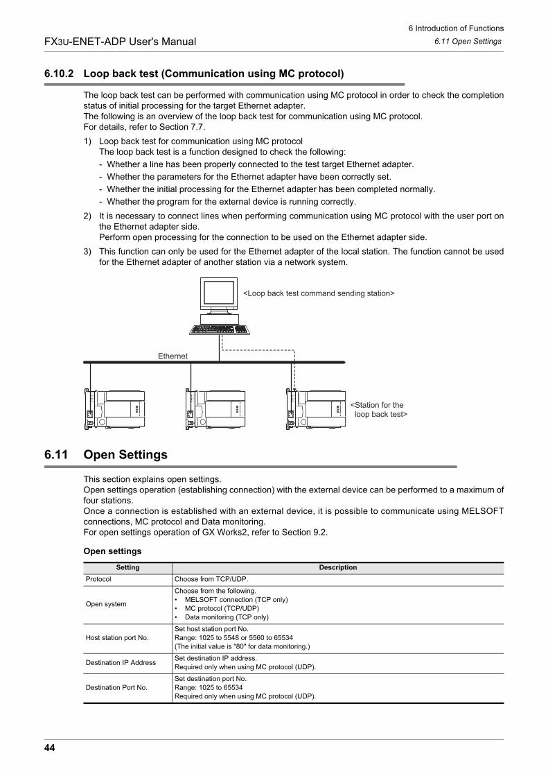
6 Introduction of Functions
44
FX3U-ENET-ADP User's Manual 6.11 Open Settings
6.10.2 Loop back test (Communication using MC protocol)
The loop back test can be performed with communication using MC protocol in order to check the completionstatus of initial processing for the target Ethernet adapter. The following is an overview of the loop back test for communication using MC protocol. For details, refer to Section 7.7.
1) Loop back test for communication using MC protocolThe loop back test is a function designed to check the following:
- Whether a line has been properly connected to the test target Ethernet adapter.
- Whether the parameters for the Ethernet adapter have been correctly set.
- Whether the initial processing for the Ethernet adapter has been completed normally.
- Whether the program for the external device is running correctly.
2) It is necessary to connect lines when performing communication using MC protocol with the user port onthe Ethernet adapter side. Perform open processing for the connection to be used on the Ethernet adapter side.
3) This function can only be used for the Ethernet adapter of the local station. The function cannot be usedfor the Ethernet adapter of another station via a network system.
6.11 Open Settings
This section explains open settings.Open settings operation (establishing connection) with the external device can be performed to a maximum offour stations.Once a connection is established with an external device, it is possible to communicate using MELSOFTconnections, MC protocol and Data monitoring.For open settings operation of GX Works2, refer to Section 9.2.
Open settings
Setting Description
Protocol Choose from TCP/UDP.
Open system
Choose from the following.
� MELSOFT connection (TCP only)
� MC protocol (TCP/UDP)
� Data monitoring (TCP only)
Host station port No.
Set host station port No.
Range: 1025 to 5548 or 5560 to 65534
(The initial value is "80" for data monitoring.)
Destination IP AddressSet destination IP address.
Required only when using MC protocol (UDP).
Destination Port No.
Set destination port No.
Range: 1025 to 65534
Required only when using MC protocol (UDP).
Ethernet
<Loop back test command sending station>
<Station for the loop back test>
6 Introduction of Functions
45
FX3U-ENET-ADP User's Manual
1
Introduction
2
Specification
3
System
C
onfiguration
4
Installation
5
Wiring
6
Introduction of F
unctions
7
Com
munication
Using
MC
Protocol
8
Data m
onitoring function
9
The O
peration of G
X W
orks2
10
Troubleshooting
6.12 Open Processing/Close Processing of the Connection
1) ProtocolSelect the protocol (communication method) for each connection between "TCP" and "UDP" inaccordance with the external device.Select "TCP" when placing importance on the reliability of communication.
For explanation of TCP/UDP, refer to Subsection 1.1.3.
2) Open systemSelect the connection open system for each connection for which "TCP" is selected in "1) Protocol". If "UDP" is selected, this specification is not required. (MC protocol)
3) Host station port No.In this item the port number of each connection for the Ethernet adapter is set. Required only when using MC protocol (TCP/UDP) and data monitoring. Setting range MC protocol : 1025 to 5548, 5552 to 65534 Data monitoring : 80 (Default), 1025 to 5548, 5560 to 65534Set port numbers that are not already used by other ports.When data monitoring is set to several connections in the open setting, the same port number should beset to all connections.Set the port numbers for the Ethernet adapter upon consulting a network administrator.
4) Destination IP AddressSet the IP address of the communication counterpart (external device) for each connection of theEthernet adapter (2 words).Required only when using MC protocol (UDP).The IP addresses of external devices must be given values other than 0.0.0.0 (00.00.00.00H), 255.255.255.255 (FF.FF.FF.FFH).Set the IP addresses of external devices upon consulting a network administrator.
5) Destination Port No.Set the port number of the communication counterpart (external device) for each connection of theEthernet adapter.Required only when using MC protocol (UDP).The port numbers of the external devices are set in the range from 1025 to 65534.Set the port numbers for the external device upon consulting a network administrator.
6.12 Open Processing/Close Processing of the Connection
This section explains the open processing/close processing of a connection.For open settings operation of GX Works2, refer to Section 9.2.
1) Open processingThe purpose of open processing is to establish a connection with an external device in order to performthe following forms of data communication. (They can be performed with an external device opened bythe user.)
- MELSOFT connection (TCP only)
- MC protocol (TCP/UDP)
- Data monitoring (TCP only)
Name of setting Description of setting
TCP Communicate using TCP/IP.
UDP Communicate using UDP/IP.
Name of setting Description of setting
MELSOFT connections Connection is opened by MELSOFT connection.
MC Protocol Connection is opened by MC Protocol.
Data monitoring Connection is opened by Data monitoring.
6 Introduction of Functions
46
FX3U-ENET-ADP User's Manual 6.12 Open Processing/Close Processing of the Connection
2) Close processingThe purpose of close processing is to disconnect (close) the connection with the external deviceestablished by open processing.Close processing is used when terminating a connection with an external device, changing an externaldevice of a connection, changing communication conditions, etc.Perform close processing for connections established by open processing using sequence programs.Determine the timing of close processing with the external device.
The Ethernet automatically closes the connection in the following cases even if a request for closing is notgiven.
� When the existence confirmation (Keep-Alive) function times out.When the protocol is set to "TCP", the Ethernet adapter executes confirmation using the existence confirmation (Keep-Alive) function.The Ethernet adapter sends a message for existence confirmation 5 seconds after receiving the last message from an external device, and checks whether or not the external device has given a response.When the external device has not given a response, the Ethernet adapter repeatedly sends a message for existence confirmation at 5-second intervals. When the Ethernet adapter cannot confirm a response for 45 seconds, it closes the connection under judgment that the external device does not exist.
� When a close or RST command is received from an external device.
� When an active open request is received again from an external device in the open completion status of TCP. After returning ACK to the external device, the Ethernet adapter disconnect (close) the connection when the RST command is received from the external device. However, when receiving an active open request again from an external device with a different IP address or port No., the Ethernet adapter only sends the RST command. (It does not close the connection.)
� When the protocol is set to "TCP" and an external device does not return ACK for 30 seconds.In the TCP connection, the Ethernet adapter executes retransmission when an external device does not return ACK in response to a transmission.The Ethernet adapter starts retransmission processing 1 second after the initial transmission, and executes retransmission 3, 7, and 15 seconds after the initial transmission (4 times in total).When the Ethernet adapter does not receive ACK from the external device for 15 seconds after the last retransmission, it closes the connection under judgment that the external device is abnormal.
Caution
� When the protocol is set to "TCP" and the external device does not support the existence confirmation (Keep-Alive) function, the Ethernet adapter may close the connection.
� Do not connect external devices beyond the number of connections available in the open setting. If TCP connections beyond the available number of connections are set from external devices, the following phenomena may occur depending on the application:
- The time after which a timeout error occurs is extended.
- A timeout error suddenly occurs in either external device under communication.
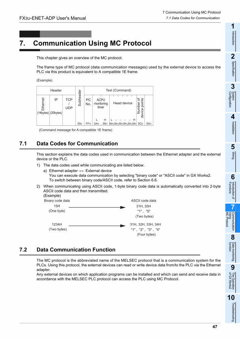
7 Communication Using MC Protocol
47
FX3U-ENET-ADP User's Manual
1
Introduction
2
Specification
3
System
C
onfiguration
4
Installation
5
Wiring
6
Introduction of F
unctions
7
Com
munication
Using
MC
Protocol
8
Data m
onitoring function
9
The O
peration of G
X W
orks2
10
Troubleshooting
7.1 Data Codes for Communication
7. Communication Using MC Protocol
This chapter gives an overview of the MC protocol.
The frame type of MC protocol (data communication messages) used by the external device to access thePLC via this product is equivalent to A compatible 1E frame.
7.1 Data Codes for Communication
This section explains the data codes used in communication between the Ethernet adapter and the externaldevice or the PLC.
1) The data codes used while communicating are listed below.
a) Ethernet adapter External deviceYou can execute data communication by selecting "binary code" or "ASCII code" in GX Works2.To switch between binary code/ASCII code, refer to Section 6.6.
2) When communicating using ASCII code, 1-byte binary code data is automatically converted into 2-byteASCII code data and then transmitted.(Example)
7.2 Data Communication Function
The MC protocol is the abbreviated name of the MELSEC protocol that is a communication system for thePLCs. Using this protocol, the external devices can read or write device data from/to the PLC via the Ethernetadapter.Any external devices on which application programs can be installed and which can send and receive data inaccordance with the MELSEC PLC protocol can access the PLC using MC Protocol.
L H H
Head device
Text (Command)
ACPUmonitoring
timer
PCNo.S
ub
he
ad
erHeader
Eth
ern
et
(14bytes)
IP
(20bytes)
TCP/
UDP
L
(Command message for A compatible 1E frame)
Nu
mb
er
of
de
vic
e p
oin
ts
00H 0AH 00H 00H 00H 00H 20H 40H 0CH 00HFFH 64H
(Example)
Binary code data
15H
(One byte)
ASCII code data
31H, 35H
(Two bytes)
(Four bytes)
"1" , "5"
1234H
(Two bytes) "4""3" ,"2" ,"1" ,
31H, 32H, 33H, 34H
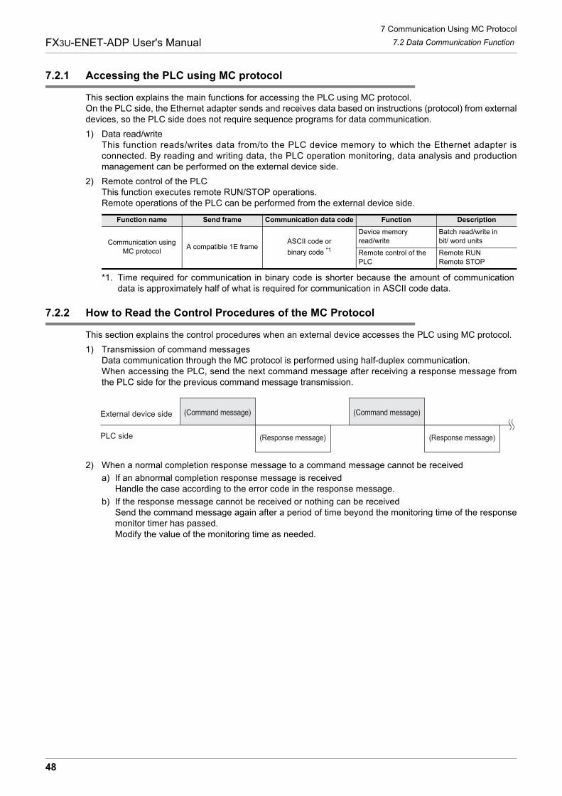
7 Communication Using MC Protocol
48
FX3U-ENET-ADP User's Manual 7.2 Data Communication Function
7.2.1 Accessing the PLC using MC protocol
This section explains the main functions for accessing the PLC using MC protocol.On the PLC side, the Ethernet adapter sends and receives data based on instructions (protocol) from externaldevices, so the PLC side does not require sequence programs for data communication.
1) Data read/writeThis function reads/writes data from/to the PLC device memory to which the Ethernet adapter isconnected. By reading and writing data, the PLC operation monitoring, data analysis and productionmanagement can be performed on the external device side.
2) Remote control of the PLCThis function executes remote RUN/STOP operations. Remote operations of the PLC can be performed from the external device side.
*1. Time required for communication in binary code is shorter because the amount of communicationdata is approximately half of what is required for communication in ASCII code data.
7.2.2 How to Read the Control Procedures of the MC Protocol
This section explains the control procedures when an external device accesses the PLC using MC protocol.
1) Transmission of command messagesData communication through the MC protocol is performed using half-duplex communication.When accessing the PLC, send the next command message after receiving a response message fromthe PLC side for the previous command message transmission.
2) When a normal completion response message to a command message cannot be received
a) If an abnormal completion response message is receivedHandle the case according to the error code in the response message.
b) If the response message cannot be received or nothing can be receivedSend the command message again after a period of time beyond the monitoring time of the responsemonitor timer has passed.Modify the value of the monitoring time as needed.
Function name Send frame Communication data code Function Description
Communication using
MC protocolA compatible 1E frame
ASCII code or
binary code *1
Device memory
read/write
Batch read/write in
bit/ word units
Remote control of the
PLC
Remote RUN
Remote STOP
External device side
PLC side
(Command message) (Command message)
(Response message) (Response message)
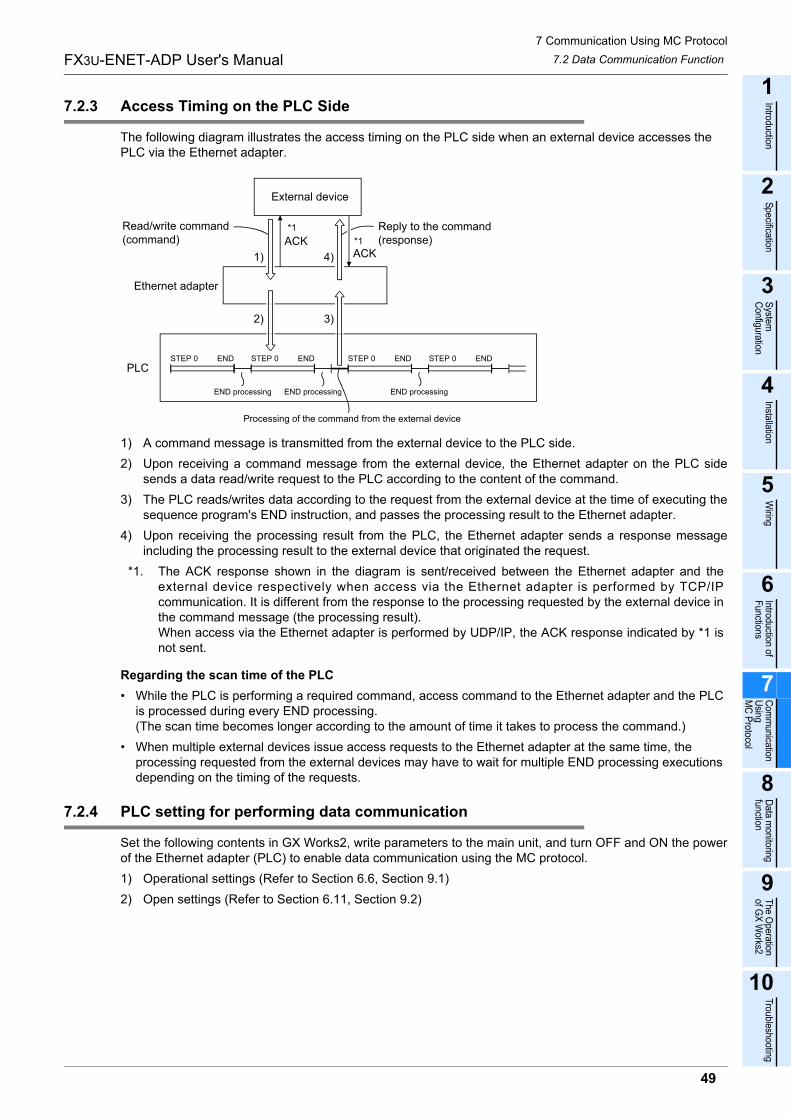
7 Communication Using MC Protocol
49
FX3U-ENET-ADP User's Manual
1
Introduction
2
Specification
3
System
C
onfiguration
4
Installation
5
Wiring
6
Introduction of F
unctions
7
Com
munication
Using
MC
Protocol
8
Data m
onitoring function
9
The O
peration of G
X W
orks2
10
Troubleshooting
7.2 Data Communication Function
7.2.3 Access Timing on the PLC Side
The following diagram illustrates the access timing on the PLC side when an external device accesses the PLC via the Ethernet adapter.
1) A command message is transmitted from the external device to the PLC side.
2) Upon receiving a command message from the external device, the Ethernet adapter on the PLC sidesends a data read/write request to the PLC according to the content of the command.
3) The PLC reads/writes data according to the request from the external device at the time of executing thesequence program's END instruction, and passes the processing result to the Ethernet adapter.
4) Upon receiving the processing result from the PLC, the Ethernet adapter sends a response messageincluding the processing result to the external device that originated the request.
*1. The ACK response shown in the diagram is sent/received between the Ethernet adapter and theexternal device respectively when access via the Ethernet adapter is performed by TCP/IPcommunication. It is different from the response to the processing requested by the external device inthe command message (the processing result). When access via the Ethernet adapter is performed by UDP/IP, the ACK response indicated by *1 isnot sent.
Regarding the scan time of the PLC
� While the PLC is performing a required command, access command to the Ethernet adapter and the PLC is processed during every END processing. (The scan time becomes longer according to the amount of time it takes to process the command.)
� When multiple external devices issue access requests to the Ethernet adapter at the same time, the processing requested from the external devices may have to wait for multiple END processing executions depending on the timing of the requests.
7.2.4 PLC setting for performing data communication
Set the following contents in GX Works2, write parameters to the main unit, and turn OFF and ON the powerof the Ethernet adapter (PLC) to enable data communication using the MC protocol.
1) Operational settings (Refer to Section 6.6, Section 9.1)
2) Open settings (Refer to Section 6.11, Section 9.2)
*1
*1
STEP 0 END STEP 0 END STEP 0 END STEP 0 END
External device
Read/write command(command)
Ethernet adapter
ACKACK
Reply to the command (response)
4)1)
3)2)
PLC
END processing END processing END processing
Processing of the command from the external device
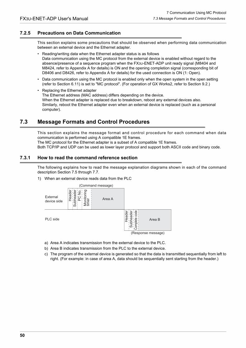
7 Communication Using MC Protocol
50
FX3U-ENET-ADP User's Manual 7.3 Message Formats and Control Procedures
7.2.5 Precautions on Data Communication
This section explains some precautions that should be observed when performing data communicationbetween an external device and the Ethernet adapter.
� Reading/writing data when the Ethernet adapter status is as followsData communication using the MC protocol from the external device is enabled without regard to the absence/presence of a sequence program when the FX3U-ENET-ADP unit ready signal (M8404 and M8424, refer to Appendix A for details) is ON and the opening completion signal (corresponding bit of D8406 and D8426, refer to Appendix A for details) for the used connection is ON (1: Open).
� Data communication using the MC protocol is enabled only when the open system in the open setting (refer to Section 6.11) is set to "MC protocol". (For operation of GX Works2, refer to Section 9.2.)
� Replacing the Ethernet adapterThe Ethernet address (MAC address) differs depending on the device.When the Ethernet adapter is replaced due to breakdown, reboot any external devices also.Similarly, reboot the Ethernet adapter even when an external device is replaced (such as a personal computer).
7.3 Message Formats and Control Procedures
This section explains the message format and control procedure for each command when datacommunication is performed using A compatible 1E frames.The MC protocol for the Ethernet adapter is a subset of A compatible 1E frames.Both TCP/IP and UDP can be used as lower layer protocol and support both ASCII code and binary code.
7.3.1 How to read the command reference section
The following explains how to read the message explanation diagrams shown in each of the commanddescription Section 7.5 through 7.7.
1) When an external device reads data from the PLC
a) Area A indicates transmission from the external device to the PLC.
b) Area B indicates transmission from the PLC to the external device.
c) The program of the external device is generated so that the data is transmitted sequentially from left toright. (For example: in case of area A, data should be sequentially sent starting from the header.)
(Command message)
External device side H
ea
de
r
Su
bh
ea
de
r
PC
No
.
Mo
nito
rin
gtim
er
PLC side He
ad
er
Su
bh
ea
de
r
Com
plet
e co
de
Area B
(Response message)
Area A
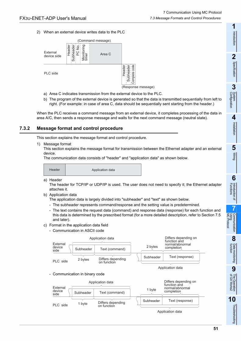
7 Communication Using MC Protocol
51
FX3U-ENET-ADP User's Manual
1
Introduction
2
Specification
3
System
C
onfiguration
4
Installation
5
Wiring
6
Introduction of F
unctions
7
Com
munication
Using
MC
Protocol
8
Data m
onitoring function
9
The O
peration of G
X W
orks2
10
Troubleshooting
7.3 Message Formats and Control Procedures
2) When an external device writes data to the PLC
a) Area C indicates transmission from the external device to the PLC.
b) The program of the external device is generated so that the data is transmitted sequentially from left toright. (For example: in case of area C, data should be sequentially sent starting from the header.)
When the PLC receives a command message from an external device, it completes processing of the data inarea A/C, then sends a response message and waits for the next command message (neutral state).
7.3.2 Message format and control procedure
This section explains the message format and control procedure.
1) Message formatThis section explains the message format for transmission between the Ethernet adapter and an externaldevice.The communication data consists of "header" and "application data" as shown below.
a) HeaderThe header for TCP/IP or UDP/IP is used. The user does not need to specify it; the Ethernet adapterattaches it.
b) Application dataThe application data is largely divided into "subheader" and "text" as shown below.
- The subheader represents command/response and the setting value is predetermined.
- The text contains the request data (command) and response data (response) for each function and this data is determined by the prescribed format (for a more detailed description, refer to Section 7.5 and later).
c) Format in the application data field
- Communication in ASCII code
- Communication in binary code
External device side
(Command message)
PLC side
He
ad
er
Su
bh
ea
de
r
PC
No
.
Mo
nito
rin
gtim
er Area C
He
ad
er
Su
bh
ea
de
r
Com
plet
e co
de
(Response message)
Header Application data
Application data
External device side
PLC side
Subheader Text (command)
2 bytes Differs depending on function
2 bytes
Differs depending on function and normal/abnormal completion
Subheader Text (response)
Application data
Application data
External deviceside Subheader Text (command)
1 byte Differs depending on functionPLC side
1 byte
Differs depending on function andnormal/abnormal completion
Subheader Text (response)
Application data
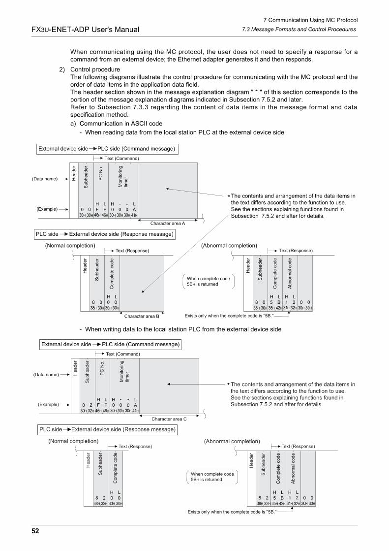
7 Communication Using MC Protocol
52
FX3U-ENET-ADP User's Manual 7.3 Message Formats and Control Procedures
When communicating using the MC protocol, the user does not need to specify a response for acommand from an external device; the Ethernet adapter generates it and then responds.
2) Control procedureThe following diagrams illustrate the control procedure for communicating with the MC protocol and theorder of data items in the application data field.The header section shown in the message explanation diagram " * " of this section corresponds to theportion of the message explanation diagrams indicated in Subsection 7.5.2 and later.Refer to Subsection 7.3.3 regarding the content of data items in the message format and dataspecification method.
a) Communication in ASCII code
- When reading data from the local station PLC at the external device side
- When writing data to the local station PLC from the external device side
External device side PLC side (Command message)
PLC side External device side (Response message)
30H 30H 30H46H 46H 41H
30H 30H 30H 30H 30H 30H35H 42H 31H 32H
(Data name)
(Example)
He
ad
er
0 0 F F-
A
Su
bh
ea
de
r
PC
No
.
Mo
nito
rin
gtim
er
Character area A
The contents and arrangement of the data items in the text differs according to the function to use.See the sections explaining functions found in Subsection 7.5.2 and after for details.
Text (Command)
(Normal completion)Text (Response)
He
ad
er
Su
bh
ea
de
r
Co
mp
lete
co
de
(Abnormal completion)Text (Response)
He
ad
er
Su
bh
ea
de
r
Co
mp
lete
co
de
Ab
no
rma
l co
de
When complete code 5BH is returned
30H
Exists only when the complete code is "5B."
38H
8 0H L5 B
H L1 2 0 0
30H
H L H L0 0 0
-
Character area B
38H
8 0H L0 0
*
External device side PLC side (Command message)
PLC side External device side (Response message)
Text (Command)
(Data name) He
ad
er
Su
bh
ea
de
r
PC
No
.
Mo
nito
rin
gtim
er
Character area C
(Normal completion)
He
ad
er
Su
bh
ea
de
r
Co
mp
lete
co
de
Text (Response)
The contents and arrangement of the data items inthe text differs according to the function to use.See the sections explaining functions found in Subsection 7.5.2 and after for details.
(Abnormal completion)Text (Response)
He
ad
er
Su
bh
ea
de
r
Co
mp
lete
co
de
Ab
no
rma
l co
de
When complete code5BH is returned
Exists only when the complete code is "5B."
(Example)H HL L- -
F F A0 0 0 0230H 30H 30H 30H32H 46H 46H 41H
H L8 2 0 0
30H30H32H38H 32H32H38H 30H30H31H35H 42H
H HL L8 52 1 2 0 0B
*
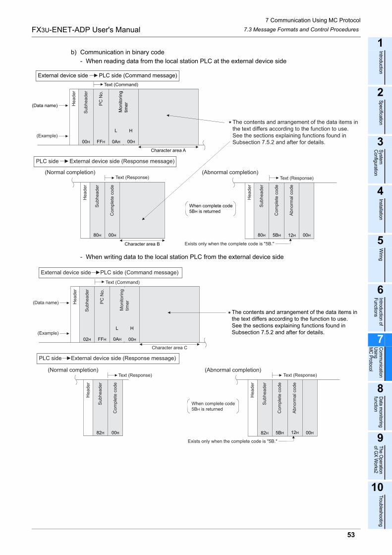
7 Communication Using MC Protocol
53
FX3U-ENET-ADP User's Manual
1
Introduction
2
Specification
3
System
C
onfiguration
4
Installation
5
Wiring
6
Introduction of F
unctions
7
Com
munication
Using
MC
Protocol
8
Data m
onitoring function
9
The O
peration of G
X W
orks2
10
Troubleshooting
7.3 Message Formats and Control Procedures
b) Communication in binary code
- When reading data from the local station PLC at the external device side
- When writing data to the local station PLC from the external device side
External device side PLC side (Command message)
PLC side External device side (Response message)
(Data name)
(Example)
He
ad
er
Su
bh
ea
de
r
PC
No
.
Mo
nito
rin
gtim
er
Text (Command)
Character area A
The contents and arrangement of the data items in the text differs according to the function to use.See the sections explaining functions found in Subsection 7.5.2 and after for details.
L H
00H FFH 0AH 00H
(Normal completion) (Abnormal completion)Text (Response)
He
ad
er
Su
bh
ea
de
r
Co
mp
lete
co
de
00H80H
Character area B
When complete code 5BH is returned
Exists only when the complete code is "5B."
Text (Response)
He
ad
er
Su
bh
ea
de
r
Co
mp
lete
co
de
80H 00H12H5BH
Ab
no
rma
l co
de
*
External device side PLC side (Command message)
PLC side External device side (Response message)
(Normal completion) (Abnormal completion)
Text (Command)
(Data name)
(Example)
He
ad
er
Su
bh
ea
de
r
PC
No
.
Mo
nito
rin
gtim
er
L H
02H FFH 0AH 00H
The contents and arrangement of the data items in the text differs according to the function to use.See the sections explaining functions found in Subsection 7.5.2 and after for details.
Text (Response)
He
ad
er
Su
bh
ea
de
r
Co
mp
lete
co
de
When complete code5BH is returned
Text (Response)
He
ad
er
Su
bh
ea
de
r
Co
mp
lete
co
de
Ab
no
rma
l co
de
Character area C
00H82H
Exists only when the complete code is "5B."
00H82H 5BH 12H
*
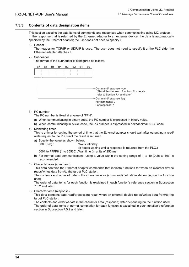
7 Communication Using MC Protocol
54
FX3U-ENET-ADP User's Manual 7.3 Message Formats and Control Procedures
7.3.3 Contents of data designation items
This section explains the data items of commands and responses when communicating using MC protocol.In the response that is returned by the Ethernet adapter to an external device, the data is automaticallyspecified by the Ethernet adapter; the user does not need to specify it.
1) HeaderThe header for TCP/IP or UDP/IP is used. The user does not need to specify it at the PLC side; theEthernet adapter attaches it.
2) SubheaderThe format of the subheader is configured as follows.
3) PC numberThe PC number is fixed at a value of "FFH".
a) When communicating in binary code, the PC number is expressed in binary value.
b) When communicating in ASCII code, the PC number is expressed in hexadecimal ASCII code.
4) Monitoring timerThis is a timer for setting the period of time that the Ethernet adapter should wait after outputting a read/write request to the PLC until the result is returned.
a) Specify the value as shown below.0000H (0) : Waits infinitely
(It keeps waiting until a response is returned from the PLC.)0001 to FFFFH (1 to 65535) :Wait time (in units of 250 ms)
b) For normal data communications, using a value within the setting range of 1 to 40 (0.25 to 10s) isrecommended.
5) Character area (command)This data contains the Ethernet adapter commands that indicate functions for when an external devicereads/writes data from/to the target PLC station.The contents and order of data in the character area (command) field differ depending on the functionused.The order of data items for each function is explained in each function's reference section in Subsection7.5.2 and later.
6) Character area (response)This data contains data read/processing result when an external device reads/writes data from/to thetarget PLC station.The contents and order of data in the character area (response) differ depending on the function used.The order of data items at normal completion for each function is explained in each function's referencesection in Subsection 7.5.2 and later.
Command/response type(This differs for each function. For details, refer to Section 7.4 and later.)
Command/response flagFor command: 0For response: 1
B7 B6 B5 B4 B3 B2 B1 B0
7 Communication Using MC Protocol
55
FX3U-ENET-ADP User's Manual
1
Introduction
2
Specification
3
System
C
onfiguration
4
Installation
5
Wiring
6
Introduction of F
unctions
7
Com
munication
Using
MC
Protocol
8
Data m
onitoring function
9
The O
peration of G
X W
orks2
10
Troubleshooting
7.3 Message Formats and Control Procedures
7) Complete codeThe result of processing when an external device reads/writes data from/to the target PLC station isindicated by the following values.00H : Normal completionOther than 00H :Abnormal completion (50 to 60H)
a) When communicating in binary code, the complete code is expressed in binary values.
b) When communicating in ASCII code, the complete code is expressed in hexadecimal ASCII code.
c) When the complete code indicates abnormal completion, check the content and take action accordingto the troubleshooting section of Chapter 10. When the complete code is 5BH/"5B," the abnormal code data (10 to 18H) and 00H/"00" are includedimmediately after.
8) Abnormal codeThis value indicates the nature of the error when the processing result of reading/writing data from/to thetarget PLC station by an external device is faulty and the complete code is 5BH/"5B." (Abnormal code: 10to 18H)
a) When communicating in binary code, the abnormal code is expressed in binary values.
b) When communicating in ASCII code, the abnormal code is expressed in hexadecimal ASCII code.
c) Check the content and take action according to the troubleshooting section of Chapter 10.
Caution
The data code (ASCII/binary) when sending/receiving commands and responses between the Ethernetadapter and an external device is determined in the operation settings in GX Works2.The external device communicating with Ethernet adapter should send the values specified in each data itemin the commands and responses in the above setting using the code shown below. Also, it should receive thecorresponding values in the code shown below.In the explanation hereafter in this section, the values specified in each item in a command and response areshown in binary values.
1) Communication in binary codeUnless specifically stated, the value shown in each explanation is sent/received in the designated order(L to H) since it is in binary.
2) Communication in ASCII codeUnless specifically stated, the value shown in each explanation is converted to hexadecimal ASCII codeand sent/received in the designated order (H to L).
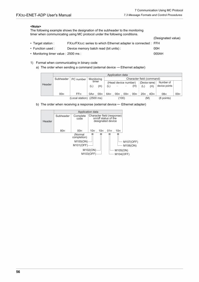
7 Communication Using MC Protocol
56
FX3U-ENET-ADP User's Manual 7.3 Message Formats and Control Procedures
<Note>The following example shows the designation of the subheader to the monitoringtimer when communicating using MC protocol under the following conditions.
(Designated value)
� Target station : FX3U/FX3UC series to which Ethernet adapter is connected : FFH
� Function used : Device memory batch read (bit units) : 00H
� Monitoring timer value : 2500 ms : 000AH
1) Format when communicating in binary code
a) The order when sending a command (external device Ethernet adapter)
b) The order when receiving a response (external device Ethernet adapter)
Application data
00H FFH 0AH 00H 64H 00H 00H 00H 20H 4DH 08H 00H
Header
(M)
(H) (L) (H) (L) (H)(L)
Subheader PC number Monitoring timer
Character field (command)
(Head device number) (Device name) Number ofdevice points
(Local station) (2500 ms) (8 points)(100)
80H 00H 10H 10H 01H 10H
M100(ON) M107(OFF)M101(OFF) M106(ON)
M102(ON) M105(ON)M103(OFF) M104(OFF)
Application data
Header
Subheader Completecode
Character field (response)on/off status of the designated device
(Normal completion)
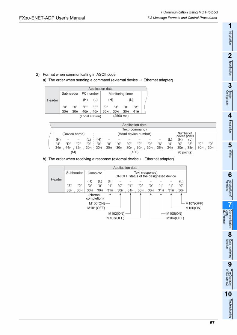
7 Communication Using MC Protocol
57
FX3U-ENET-ADP User's Manual
1
Introduction
2
Specification
3
System
C
onfiguration
4
Installation
5
Wiring
6
Introduction of F
unctions
7
Com
munication
Using
MC
Protocol
8
Data m
onitoring function
9
The O
peration of G
X W
orks2
10
Troubleshooting
7.3 Message Formats and Control Procedures
2) Format when communicating in ASCII code
a) The order when sending a command (external device Ethernet adapter)
b) The order when receiving a response (external device Ethernet adapter)
30H 30H 46H 46H 30H 30H 30H 41H
"0" "0" "F" "F" "0" "0" "0" "A"
(L)(H)(L)(H)
30H30H38H30H34H36H30H30H30H30H30H30H30H32H44H34H
"0""0""8""0""4""0""0""0""0""0""0""0""2""D""4" "6"
(H) (L) (H) (L)(H) (L)
(100)
Header
Application data
Subheader PC number Monitoring timer
(Local station) (2500 ms)
Application data
Text (command)
(Device name) (Head device number) Number of device points
(M) (8 points)
31H 30H 31H 30H
M100(ON) M107(OFF)
M101(OFF)
M102(ON) M105(ON)
M103(OFF) M104(OFF)
30H30H30H38H 30H 31H 31H 30H
"8"
M106(ON)
"0" "0"
(H)
"0"
(L)
"1"
(H)
"0" "1" "0" "0" "1" "1" "0"
(L)Header
Subheader Complete
(Normal completion)
Application data
Text (response)ON/OFF status of the designated device
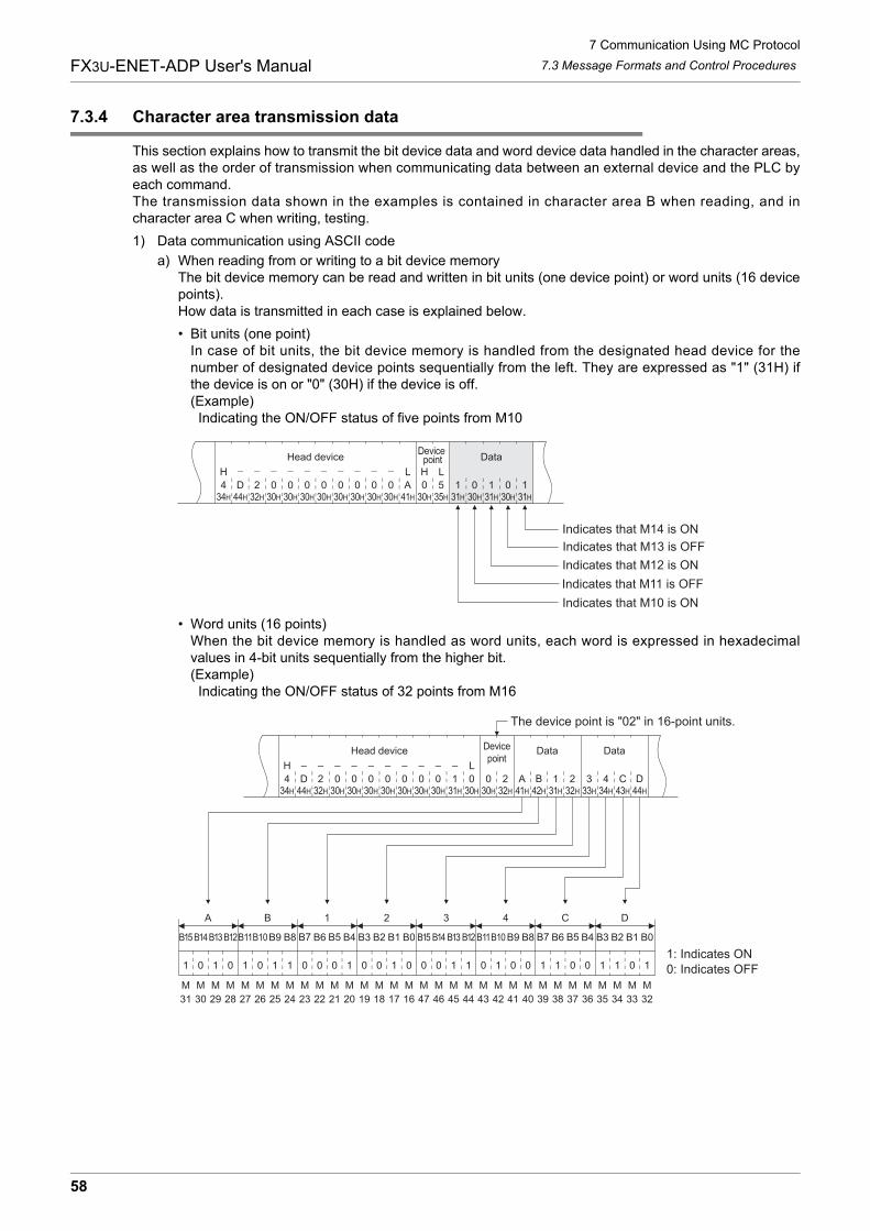
7 Communication Using MC Protocol
58
FX3U-ENET-ADP User's Manual 7.3 Message Formats and Control Procedures
7.3.4 Character area transmission data
This section explains how to transmit the bit device data and word device data handled in the character areas,as well as the order of transmission when communicating data between an external device and the PLC byeach command.The transmission data shown in the examples is contained in character area B when reading, and incharacter area C when writing, testing.
1) Data communication using ASCII code
a) When reading from or writing to a bit device memoryThe bit device memory can be read and written in bit units (one device point) or word units (16 devicepoints).How data is transmitted in each case is explained below.
� Bit units (one point)In case of bit units, the bit device memory is handled from the designated head device for thenumber of designated device points sequentially from the left. They are expressed as "1" (31H) ifthe device is on or "0" (30H) if the device is off.(Example) Indicating the ON/OFF status of five points from M10
� Word units (16 points)When the bit device memory is handled as word units, each word is expressed in hexadecimalvalues in 4-bit units sequentially from the higher bit.(Example) Indicating the ON/OFF status of 32 points from M16
Indicates that M14 is ON
Indicates that M13 is OFF
Indicates that M12 is ON
Indicates that M11 is OFF
Indicates that M10 is ON
030H
030H
A41H
030H
535H
131H
030H
131H
030H
131H
030H
030H
030H
030H44H
D34H
4
L LHH
232H
030H
030H
Head deviceDevice
point Data
030H
030H
A41H
B42H
131H
232H
333H
434H
C43H
D44H
131H
030H
030H
232H
B15
1 0 1 0 1 0 1 1 0 0 0 1 0 0 1 0 0 0 1 1
B14B13B12B11B10B9 B8 B7 B6 B5 B4 B3 B2 B1 B0
0 1 0 0 1 1 0 0 1 1 0 1
B15 B14 B13 B12 B11B10 B9 B8 B7 B6 B5 B4 B3 B2 B1 B0
A B 1 2 3 4 C D
31 30 29 28 27 26 25 24 23 22 21 20 19 18 17 16 47 46 45 44 43 42 41 40 39 38 37 36 35 34 33 32
30H
030H
032H
244H
D
– – – – – – – – – –
34H
4
LH
030H
030H
030H
Head device Devicepoint
Data Data
The device point is "02" in 16-point units.
1: Indicates ON0: Indicates OFF
M M M M M M M M M M M M M M M M M M M M M M M M M M M M M M M M
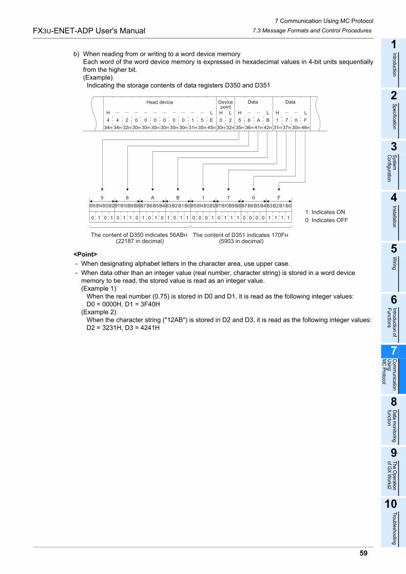
7 Communication Using MC Protocol
59
FX3U-ENET-ADP User's Manual
1
Introduction
2
Specification
3
System
C
onfiguration
4
Installation
5
Wiring
6
Introduction of F
unctions
7
Com
munication
Using
MC
Protocol
8
Data m
onitoring function
9
The O
peration of G
X W
orks2
10
Troubleshooting
7.3 Message Formats and Control Procedures
b) When reading from or writing to a word device memoryEach word of the word device memory is expressed in hexadecimal values in 4-bit units sequentiallyfrom the higher bit.(Example) Indicating the storage contents of data registers D350 and D351
<Point>
- When designating alphabet letters in the character area, use upper case.
- When data other than an integer value (real number, character string) is stored in a word device memory to be read, the stored value is read as an integer value.(Example 1) When the real number (0.75) is stored in D0 and D1, it is read as the following integer values: D0 = 0000H, D1 = 3F40H(Example 2) When the character string ("12AB") is stored in D2 and D3, it is read as the following integer values: D2 = 3231H, D3 = 4241H
30H
0 0
30H
0
30H
0
30H
1
31H
5
35H
6
36H
A
41H
B
42H
1
31H
7
37H
0
30H
F
46H
5
35H
E
45H
0
30H
2
32H32H
2
L H L H LH L
34H
4
34H
4
H
30H 30H
00
B15
0 1 0 1 0 1 1 0 1 0 1 0 1 0 1 1 0 0 0 1
B14B13B12B11B10B9B8B7B6B5B4B3B2B1B0
0 1 1 1 0 0 0 0 1 1 1 1
B15B14B13B12B11B10B9B8B7B6B5B4B3B2B1B0
5 6 A B 1 7 0 F
Head device Devicepoint
Data Data
1: Indicates ON
0: Indicates OFF
The content of D350 indicates 56ABH (22187 in decimal)
The content of D351 indicates 170FH (5903 in decimal)
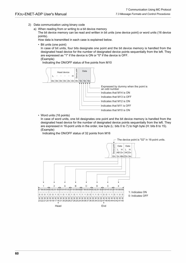
7 Communication Using MC Protocol
60
FX3U-ENET-ADP User's Manual 7.3 Message Formats and Control Procedures
2) Data communication using binary code
a) When reading from or writing to a bit device memoryThe bit device memory can be read and written in bit units (one device point) or word units (16 devicepoints).How data is transmitted in each case is explained below.
� Bit units (one point)In case of bit units, four bits designate one point and the bit device memory is handled from thedesignated head device for the number of designated device points sequentially from the left. Theyare expressed as "1" if the device is ON or "0" if the device is OFF.(Example) Indicating the ON/OFF status of five points from M10
� Word units (16 points)In case of word units, one bit designates one point and the bit device memory is handled from thedesignated head device for the number of designated device points sequentially from the left. Theyare expressed in 16-point units in the order, low byte (L: bits 0 to 7) to high byte (H: bits 8 to 15).(Example) Indicating the ON/OFF status of 32 points from M16
0AH
L
00H 00H
H
20H00H 40H 05H 10H 10H 10H
Head deviceData
Expressed by dummy when the point is an odd number
Indicates that M14 is ON
Indicates that M13 is OFF
Indicates that M12 is ON
Indicates that M11 is OFF
Indicates that M10 is ON
Dev
ice
poin
t
02H 12H ABH CDH 34H
B7
0 0 0 1 0 0 1 0 1 0 1 0 1 0 1 1 1 1 0 0
B6B5B4B3B2B1B0 B15 B14 B13 B12 B11B10B9B8
1 1 0 1 0 0 1 1 0 1 0 0
B7B6B5B4B3B2B1B0B15B14B13B12B11B10B9B8
1 2 A B C D 3 4
2322212019181716313029282726252439383736353433324746454443424140
L H
Data
The device point is "02" in 16-point units.
1: Indicates ON
0: Indicates OFFM M M M M M M M M M M M M M M M M M M M M M M M M M M M M M M M
34CDH
L H
Data
AB12HDev
ice
poin
t
Head End
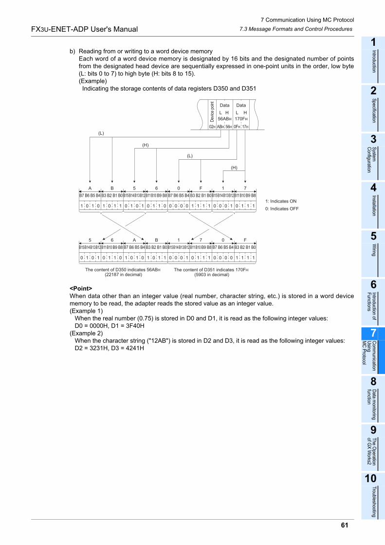
7 Communication Using MC Protocol
61
FX3U-ENET-ADP User's Manual
1
Introduction
2
Specification
3
System
C
onfiguration
4
Installation
5
Wiring
6
Introduction of F
unctions
7
Com
munication
Using
MC
Protocol
8
Data m
onitoring function
9
The O
peration of G
X W
orks2
10
Troubleshooting
7.3 Message Formats and Control Procedures
b) Reading from or writing to a word device memoryEach word of a word device memory is designated by 16 bits and the designated number of pointsfrom the designated head device are sequentially expressed in one-point units in the order, low byte(L: bits 0 to 7) to high byte (H: bits 8 to 15).(Example) Indicating the storage contents of data registers D350 and D351
<Point>When data other than an integer value (real number, character string, etc.) is stored in a word devicememory to be read, the adapter reads the stored value as an integer value.(Example 1) When the real number (0.75) is stored in D0 and D1, it is read as the following integer values: D0 = 0000H, D1 = 3F40H(Example 2) When the character string ("12AB") is stored in D2 and D3, it is read as the following integer values: D2 = 3231H, D3 = 4241H
02H ABH 56H 0FH 17H
B7
1 0 1 0 1 0 1 1 0 1 0 1 0 1 1 0 0 0 0 0
B6 B5 B4 B3 B2 B1 B0 B15B14B13B12B11B10 B9 B8
1 1 1 1 0 0 0 1 0 1 1 1
B7 B6 B5 B4 B3 B2 B1 B0 B15B14B13B12B11B10 B9 B8
A B 5 6 0 F 1 7
L H
B15
0 1 0 1 0 1 1 0 1 0 1 0 1 0 1 1 0 0 0 1
B14B13B12B11B10 B9 B8 B7 B6 B5 B4 B3 B2 B1 B0
0 1 1 1 0 0 0 0 1 1 1 1
B15B14B13B12B11B10 B9 B8 B7 B6 B5 B4 B3 B2 B1 B0
5 6 A B 1 7 0 F
Data
1: Indicates ON
0: Indicates OFF
170FH
L H
Data
56ABHDev
ice
poin
t
The content of D350 indicates 56ABH (22187 in decimal)
The content of D351 indicates 170FH (5903 in decimal)
(L)
(H)
(L)
(H)
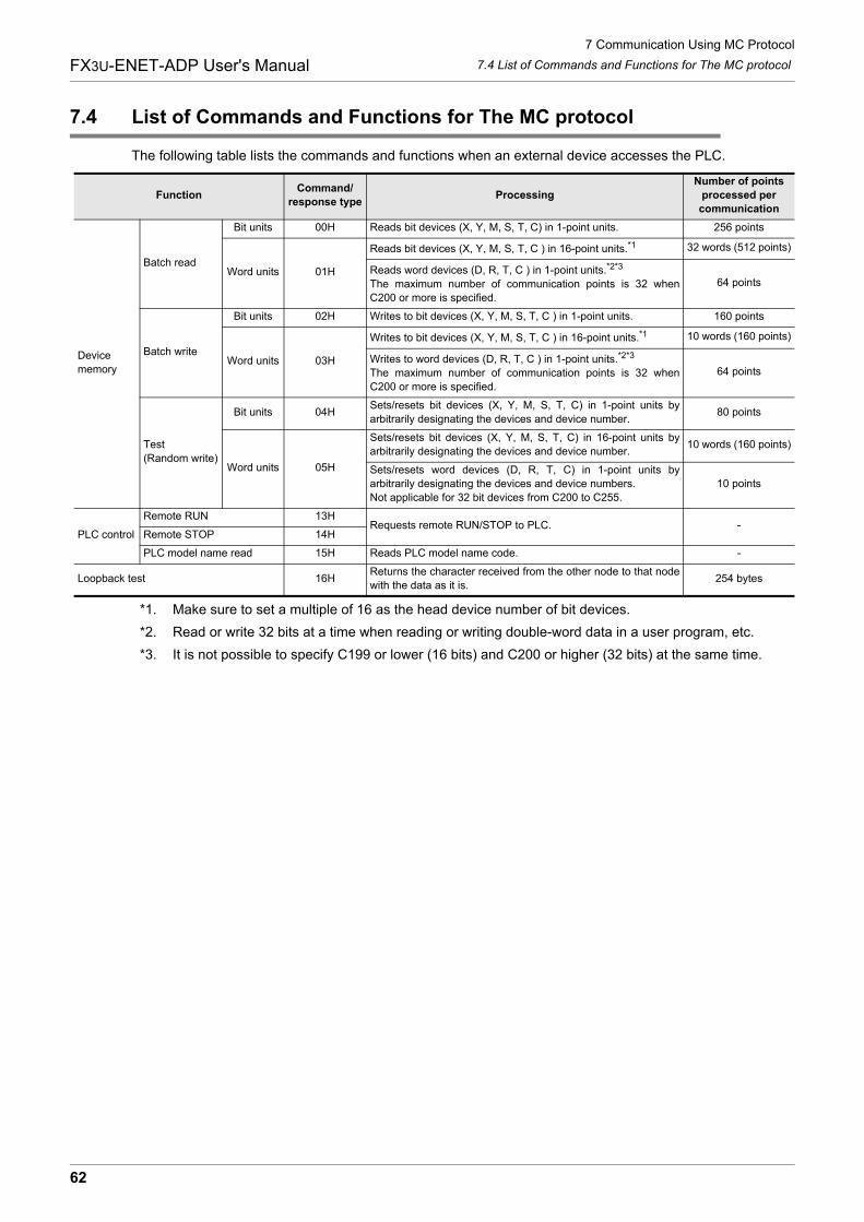
7 Communication Using MC Protocol
62
FX3U-ENET-ADP User's Manual 7.4 List of Commands and Functions for The MC protocol
7.4 List of Commands and Functions for The MC protocol
The following table lists the commands and functions when an external device accesses the PLC.
*1. Make sure to set a multiple of 16 as the head device number of bit devices.
*2. Read or write 32 bits at a time when reading or writing double-word data in a user program, etc.
*3. It is not possible to specify C199 or lower (16 bits) and C200 or higher (32 bits) at the same time.
FunctionCommand/
response typeProcessing
Number of points
processed per
communication
Device
memory
Batch read
Bit units 00H Reads bit devices (X, Y, M, S, T, C) in 1-point units. 256 points
Word units 01H
Reads bit devices (X, Y, M, S, T, C ) in 16-point units.*1 32 words (512 points)
Reads word devices (D, R, T, C ) in 1-point units.*2*3
The maximum number of communication points is 32 when
C200 or more is specified.
64 points
Batch write
Bit units 02H Writes to bit devices (X, Y, M, S, T, C ) in 1-point units. 160 points
Word units 03H
Writes to bit devices (X, Y, M, S, T, C ) in 16-point units.*1 10 words (160 points)
Writes to word devices (D, R, T, C ) in 1-point units.*2*3
The maximum number of communication points is 32 when
C200 or more is specified.
64 points
Test
(Random write)
Bit units 04HSets/resets bit devices (X, Y, M, S, T, C) in 1-point units by
arbitrarily designating the devices and device number.80 points
Word units 05H
Sets/resets bit devices (X, Y, M, S, T, C) in 16-point units by
arbitrarily designating the devices and device number.10 words (160 points)
Sets/resets word devices (D, R, T, C) in 1-point units by
arbitrarily designating the devices and device numbers.
Not applicable for 32 bit devices from C200 to C255.
10 points
PLC control
Remote RUN 13HRequests remote RUN/STOP to PLC. -
Remote STOP 14H
PLC model name read 15H Reads PLC model name code. -
Loopback test 16HReturns the character received from the other node to that node
with the data as it is.254 bytes

7 Communication Using MC Protocol
63
FX3U-ENET-ADP User's Manual
1
Introduction
2
Specification
3
System
C
onfiguration
4
Installation
5
Wiring
6
Introduction of F
unctions
7
Com
munication
Using
MC
Protocol
8
Data m
onitoring function
9
The O
peration of G
X W
orks2
10
Troubleshooting
7.4 List of Commands and Functions for The MC protocol
MEMO
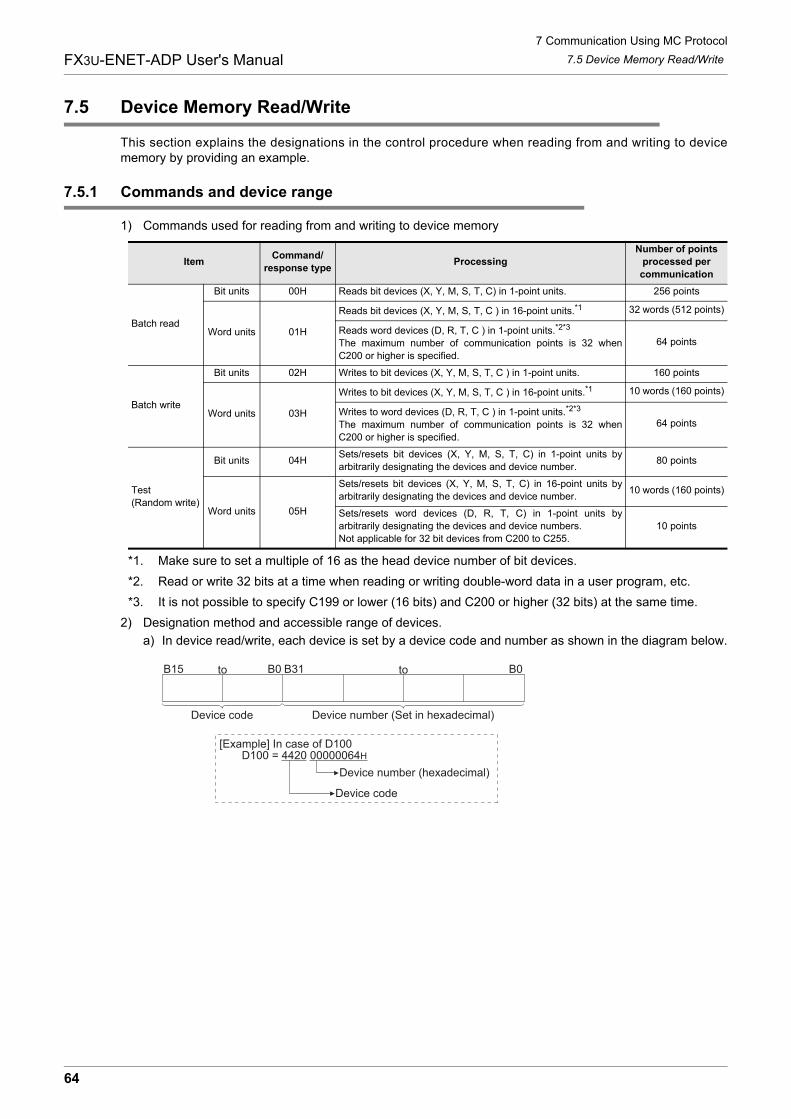
7 Communication Using MC Protocol
64
FX3U-ENET-ADP User's Manual 7.5 Device Memory Read/Write
7.5 Device Memory Read/Write
This section explains the designations in the control procedure when reading from and writing to devicememory by providing an example.
7.5.1 Commands and device range
1) Commands used for reading from and writing to device memory
*1. Make sure to set a multiple of 16 as the head device number of bit devices.
*2. Read or write 32 bits at a time when reading or writing double-word data in a user program, etc.
*3. It is not possible to specify C199 or lower (16 bits) and C200 or higher (32 bits) at the same time.
2) Designation method and accessible range of devices.
a) In device read/write, each device is set by a device code and number as shown in the diagram below.
ItemCommand/
response typeProcessing
Number of points
processed per
communication
Batch read
Bit units 00H Reads bit devices (X, Y, M, S, T, C) in 1-point units. 256 points
Word units 01H
Reads bit devices (X, Y, M, S, T, C ) in 16-point units.*1 32 words (512 points)
Reads word devices (D, R, T, C ) in 1-point units.*2*3
The maximum number of communication points is 32 when
C200 or higher is specified.
64 points
Batch write
Bit units 02H Writes to bit devices (X, Y, M, S, T, C ) in 1-point units. 160 points
Word units 03H
Writes to bit devices (X, Y, M, S, T, C ) in 16-point units.*1 10 words (160 points)
Writes to word devices (D, R, T, C ) in 1-point units.*2*3
The maximum number of communication points is 32 when
C200 or higher is specified.
64 points
Test
(Random write)
Bit units 04HSets/resets bit devices (X, Y, M, S, T, C) in 1-point units by
arbitrarily designating the devices and device number.80 points
Word units 05H
Sets/resets bit devices (X, Y, M, S, T, C) in 16-point units by
arbitrarily designating the devices and device number.10 words (160 points)
Sets/resets word devices (D, R, T, C) in 1-point units by
arbitrarily designating the devices and device numbers.
Not applicable for 32 bit devices from C200 to C255.
10 points
B15 B0 B31 B0to to
Device code Device number (Set in hexadecimal)
[Example] In case of D100D100 = 4420 00000064H
Device number (hexadecimal)
Device code
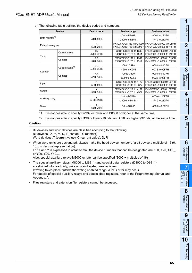
7 Communication Using MC Protocol
65
FX3U-ENET-ADP User's Manual
1
Introduction
2
Specification
3
System
C
onfiguration
4
Installation
5
Wiring
6
Introduction of F
unctions
7
Com
munication
Using
MC
Protocol
8
Data m
onitoring function
9
The O
peration of G
X W
orks2
10
Troubleshooting
7.5 Device Memory Read/Write
b) The following table outlines the device codes and numbers.
*1. It is not possible to specify D7999 or lower and D8000 or higher at the same time.
*2. It is not possible to specify C199 or lower (16 bits) and C200 or higher (32 bits) at the same time.
Caution
� Bit devices and word devices are classified according to the following.Bit devices : X, Y, M, S, T (contact), C (contact)Word devices :T (current value), C (current value), D, R
� When word units are designated, always make the head device number of a bit device a multiple of 16 (0, 16... in decimal representation).For X and Y is expressed in octadecimal, the device numbers that can be designated are X00, X20, X40,,, or Y00, Y20, Y40,,,.Also, special auxiliary relays M8000 or later can be specified (8000 + multiples of 16).
� The special auxiliary relays (M8000 to M8511) and special data registers (D8000 to D8511)are divided into read only, write only and system use registers.If writing takes place outside the writing enabled range, a PLC error may occur.For details of special auxiliary relays and special data registers, refer to the Programming Manual and Appendix A.
� Files registers and extension file registers cannot be accessed.
Device Device code Device range Device number
Data register*1D
(44H, 20H)
D0 to D7999 0000 to 1F3FH
D8000 to D8511 1F40 to 213FH
Extension registerR
(52H, 20H)
FX3G/FX3GC: R0 to R23999
FX3U/FX3UC: R0 to R32767
FX3G/FX3GC: 0000 to 5DBFH
FX3U/FX3UC: 0000 to 7FFFH
Timer
Current valueTN
(54H, 4EH)
FX3G/FX3GC: T0 to T319
FX3U/FX3UC: T0 to T511
FX3G/FX3GC: 0000 to 013FH
FX3U/FX3UC: 0000 to 01FFH
ContactTS
(54H, 53H)
FX3G/FX3GC: T0 to T319
FX3U/FX3UC: T0 to T511
FX3G/FX3GC: 0000 to 013FH
FX3U/FX3UC: 0000 to 01FFH
Counter
Current value*2 CN
(43H, 4EH)
C0 to C199 0000 to 00C7H
C200 to C255 00C8 to 00FFH
ContactCS
(43H, 53H)
C0 to C199 0000 to 00C7H
C200 to C255 00C8 to 00FFH
InputX
(58H, 20H)
FX3G/FX3GC: X0 to X177
FX3U/FX3UC: X0 to X377
FX3G/FX3GC: 0000 to 007FH
FX3U/FX3UC: 0000 to 00FFH
OutputY
(59H, 20H)
FX3G/FX3GC: Y0 to Y177
FX3U/FX3UC: Y0 to Y377
FX3G/FX3GC: 0000 to 007FH
FX3U/FX3UC: 0000 to 00FFH
Auxiliary relayM
(4DH, 20H)
M0 to M7679 0000 to 1DFFH
M8000 to M8511 1F40 to 213FH
StateS
(53H, 20H)S0 to S4095 0000 to 0FFFH
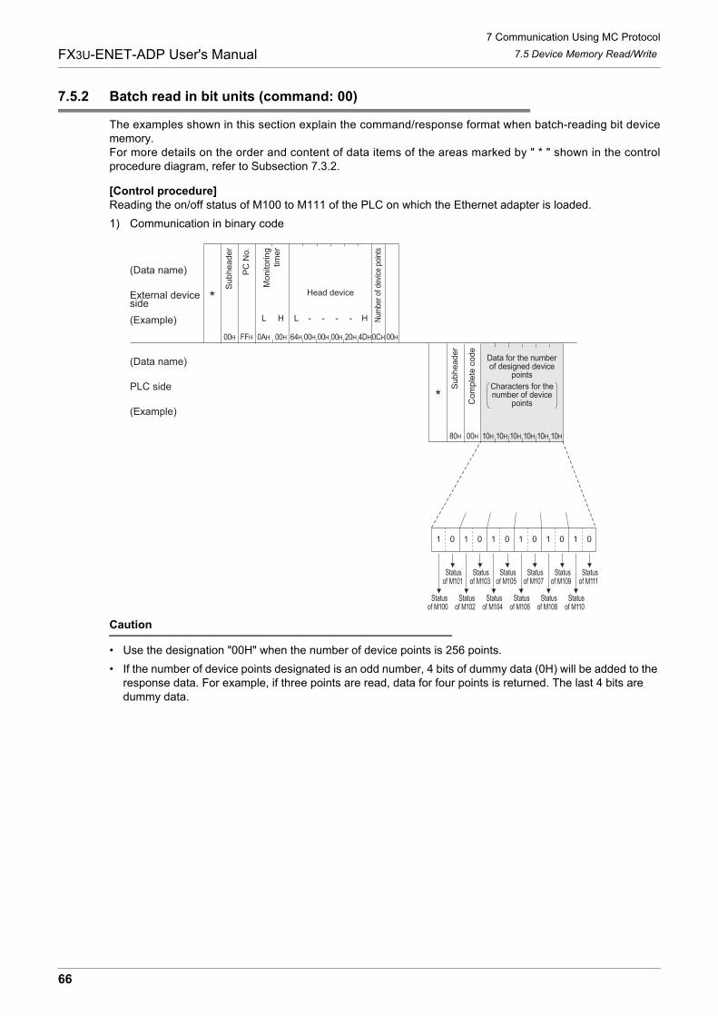
7 Communication Using MC Protocol
66
FX3U-ENET-ADP User's Manual 7.5 Device Memory Read/Write
7.5.2 Batch read in bit units (command: 00)
The examples shown in this section explain the command/response format when batch-reading bit devicememory.For more details on the order and content of data items of the areas marked by " * " shown in the controlprocedure diagram, refer to Subsection 7.3.2.
[Control procedure]Reading the on/off status of M100 to M111 of the PLC on which the Ethernet adapter is loaded.
1) Communication in binary code
Caution
� Use the designation "00H" when the number of device points is 256 points.
� If the number of device points designated is an odd number, 4 bits of dummy data (0H) will be added to the response data. For example, if three points are read, data for four points is returned. The last 4 bits are dummy data.
0AH 64H 00H
Su
bh
ea
de
r
PC
No
.
Num
ber
of d
evic
e po
ints
Head device
(Data name)
External deviceside
(Example)
(Data name)
PLC side
(Example)
00H FFH 00H 00H 00H 20H 4DH0CH 00H
80H
Su
bh
ea
de
r
Co
mp
lete
co
de
00H 10H 10H 10H 10H 10H 10H
Data for the numberof designed device
points
Characters for thenumber of device
points
01 01 01 01 01 01
Statusof M100
Statusof M101
Statusof M102
Statusof M103
Statusof M104
Statusof M105
Statusof M106
Statusof M107
Statusof M108
Statusof M109
Statusof M110
Statusof M111
Mo
nito
rin
gtim
er
HL L - - - - H
*
*
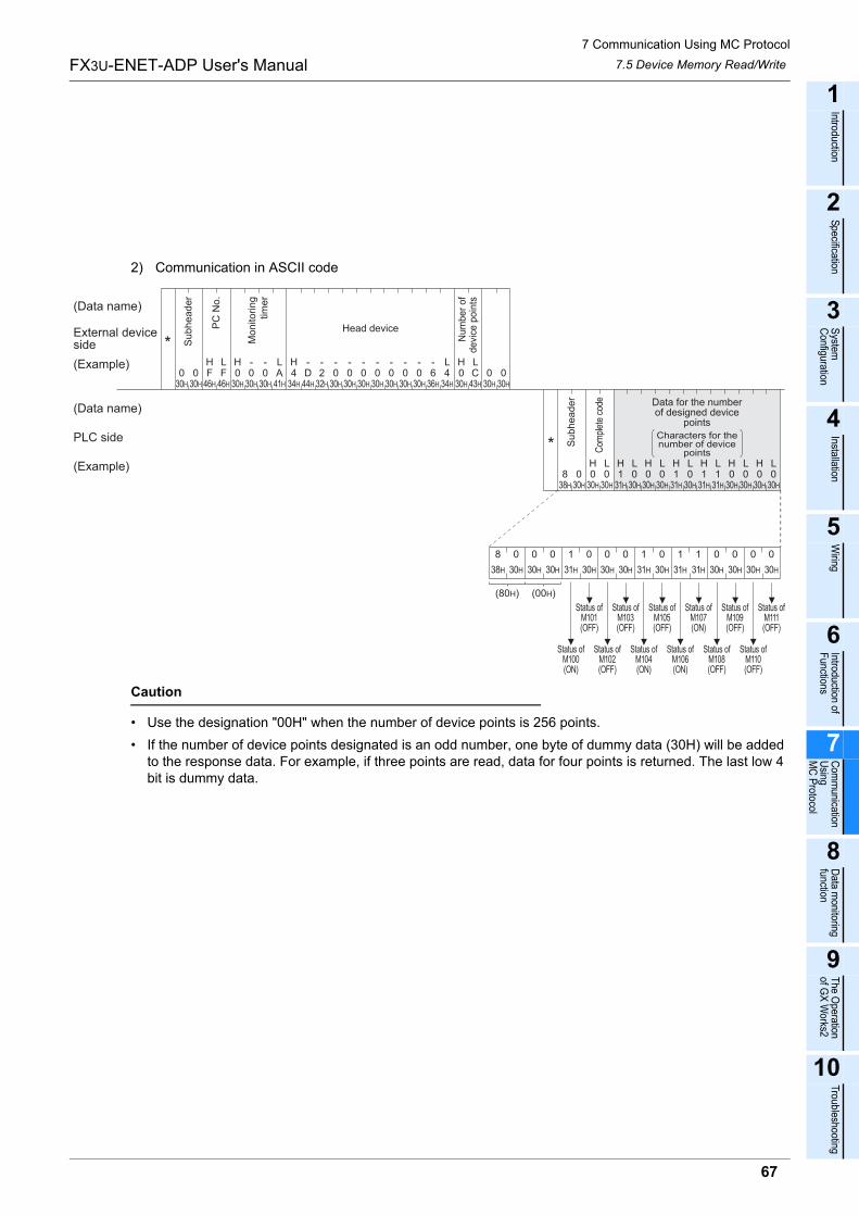
7 Communication Using MC Protocol
67
FX3U-ENET-ADP User's Manual
1
Introduction
2
Specification
3
System
C
onfiguration
4
Installation
5
Wiring
6
Introduction of F
unctions
7
Com
munication
Using
MC
Protocol
8
Data m
onitoring function
9
The O
peration of G
X W
orks2
10
Troubleshooting
7.5 Device Memory Read/Write
2) Communication in ASCII code
Caution
� Use the designation "00H" when the number of device points is 256 points.
� If the number of device points designated is an odd number, one byte of dummy data (30H) will be added to the response data. For example, if three points are read, data for four points is returned. The last low 4 bit is dummy data.
F46H 30H
030H
030H
041H
A30H
030H
030H
0F46H
H L H L H
030H
H L
34H
436H
630H
043H
C232H
D44H 30H
030H
030H
030H
0L H L
30H
030H
0
30H
0
30H
030H
034H
4
30H
038H
831H
1H L
30H
030H
030H
0L H H L
30H
030H
030H
030H
0HLH L
30H
031H
131H
131H
1HL
30H
0
30H
0
30H
0
38H
8
31H
1
30H
0
30H
0
30H
0
30H
0
30H
0
30H
0
30H
0
30H
0
31H
1
31H
1
31H
1
(80H) (00H)
Status ofM100(ON)
Status ofM101(OFF)
Status ofM102(OFF)
Status ofM103(OFF)
Status ofM104(ON)
Status ofM105(OFF)
Status ofM106(ON)
Status ofM107(ON)
Status ofM108(OFF)
Status ofM109(OFF)
Status ofM110(OFF)
Status ofM111(OFF)
- - - - - --- ----
Su
bh
ea
de
r
PC
No
.
Num
ber
of
devi
ce p
oin
ts
Head device
(Data name)
External deviceside
(Example)
(Data name)
PLC side
(Example)
Mo
nito
rin
gtim
er
Su
bh
ea
de
r
Com
plet
e co
de Data for the numberof designed device
points
Characters for thenumber of device
points*
*
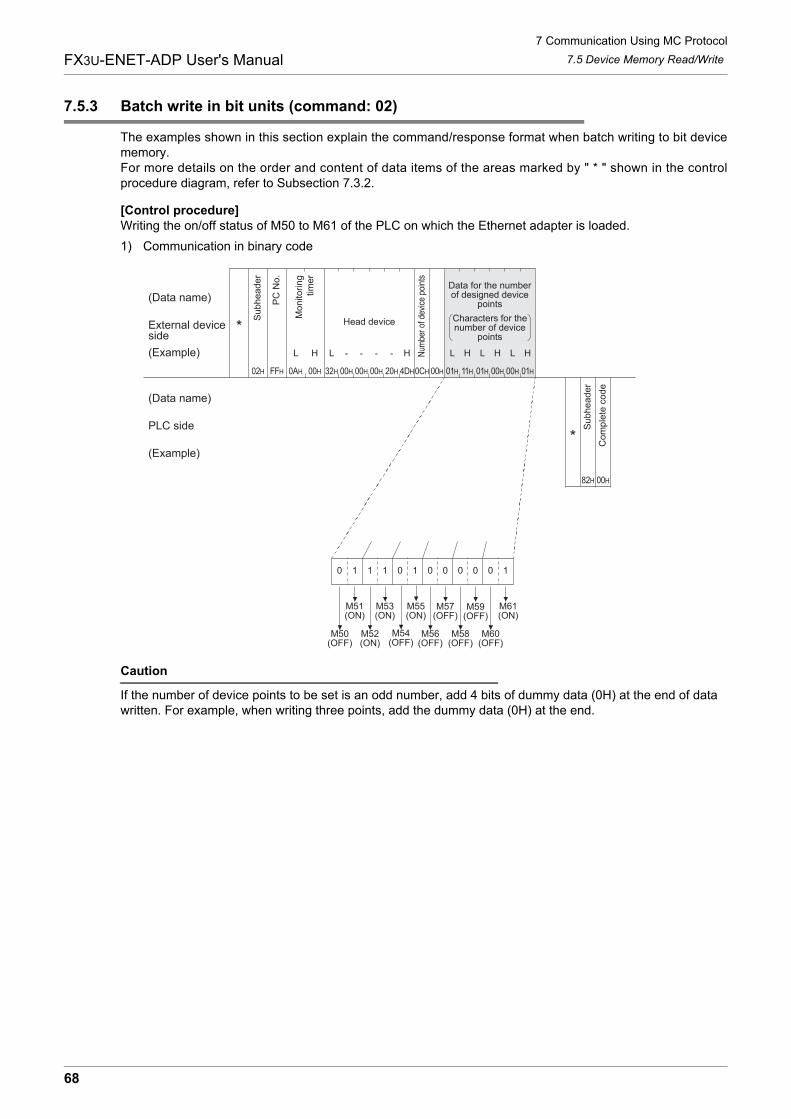
7 Communication Using MC Protocol
68
FX3U-ENET-ADP User's Manual 7.5 Device Memory Read/Write
7.5.3 Batch write in bit units (command: 02)
The examples shown in this section explain the command/response format when batch writing to bit devicememory.For more details on the order and content of data items of the areas marked by " * " shown in the controlprocedure diagram, refer to Subsection 7.3.2.
[Control procedure]Writing the on/off status of M50 to M61 of the PLC on which the Ethernet adapter is loaded.
1) Communication in binary code
Caution
If the number of device points to be set is an odd number, add 4 bits of dummy data (0H) at the end of data written. For example, when writing three points, add the dummy data (0H) at the end.
0AH 32H 00H
(Data name)
External deviceside
(Example)
(Data name)
PLC side
(Example)
02H FFH 00H 00H 00H 20H 0CH 00H
82H 00H
HL L
4DH 01H 11H 01H 00H 00H 01H
H L H L H L H
10 11 10 00 00 10
M50(OFF)
M51(ON)
M52(ON)
M53(ON)
M54(OFF)
M56(OFF)
M55(ON)
M58(OFF)
M59(OFF)
M60(OFF)
M61(ON)
M57(OFF)
- - - -
Su
bh
ea
de
r
PC
No
.
Num
ber
of d
evic
e po
ints
Head device
Mo
nito
rin
gtim
er
Data for the numberof designed device
points
Characters for thenumber of device
points
Su
bh
ea
de
r
Co
mp
lete
co
de
*
*

7 Communication Using MC Protocol
69
FX3U-ENET-ADP User's Manual
1
Introduction
2
Specification
3
System
C
onfiguration
4
Installation
5
Wiring
6
Introduction of F
unctions
7
Com
munication
Using
MC
Protocol
8
Data m
onitoring function
9
The O
peration of G
X W
orks2
10
Troubleshooting
7.5 Device Memory Read/Write
2) Communication in ASCII code
Caution
If the number of device points to be set is an odd number, add one byte of dummy data (30H) at the end of data written. For example, when writing three points, add the dummy data (30H) at the end.
(Data name)
External deviceside
(Example)
(Data name)
PLC side
(Example)
38H
830H
H
This designates to turn M50 ON
32H
230H
LThis designates to turn M51 ON
This designates to turn M60 OFF
This designates to turn M61 ON
30H
0H L0
30H
C43H
030H
131H
131H
131H
030H
030H
F46H 30H
030H
030H
041H
AF46H
H L H L
32H
2 232H
H
32H
244H
D34H
433H
330H
030H
030H
030H
030H
030H
030H
0L
00
- - -- -- - - - - - -- - - -
Su
bh
ea
de
r
Com
plet
e co
de
Su
bh
ea
de
r
PC
No
.
Nu
mb
er
of
de
vic
e p
oin
ts
Head deviceMonitoringtimer
Data for the numberof designed device points
Characters for thenumber of device points
*
*
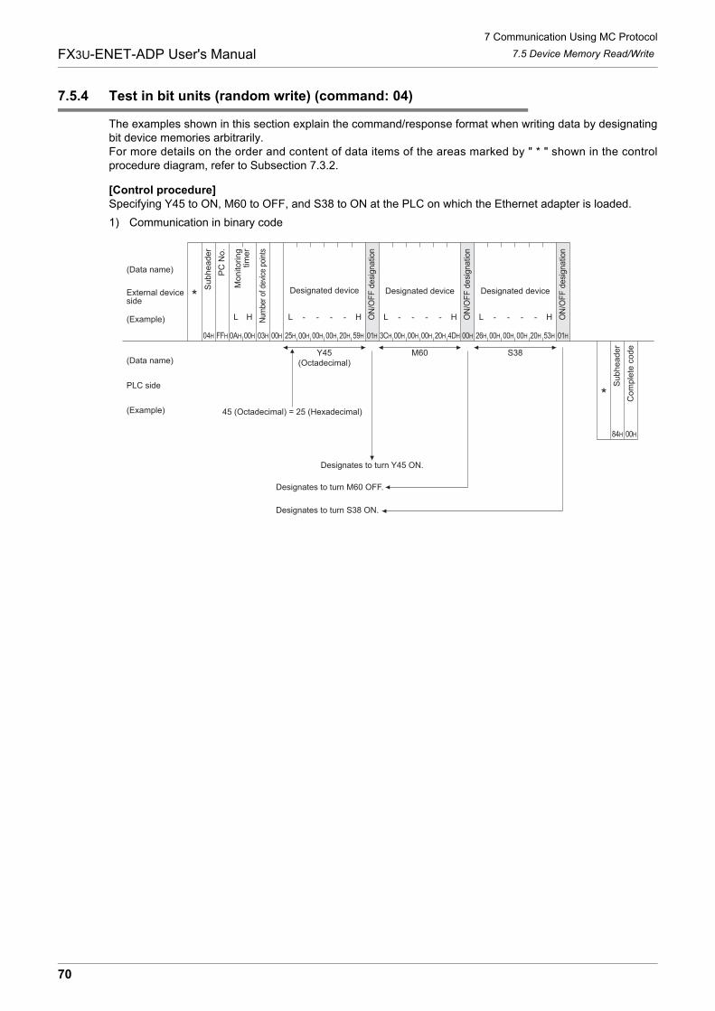
7 Communication Using MC Protocol
70
FX3U-ENET-ADP User's Manual 7.5 Device Memory Read/Write
7.5.4 Test in bit units (random write) (command: 04)
The examples shown in this section explain the command/response format when writing data by designatingbit device memories arbitrarily.For more details on the order and content of data items of the areas marked by " * " shown in the controlprocedure diagram, refer to Subsection 7.3.2.
[Control procedure]Specifying Y45 to ON, M60 to OFF, and S38 to ON at the PLC on which the Ethernet adapter is loaded.
1) Communication in binary code
H
FFH 0AH 00H 01H 3CH
(Data name)
External deviceside
(Example)
(Data name)
PLC side
(Example)
4DH04H
Designated deviceDesignated device
03H 00H 00H 00H 00H 20H 59H 00H 00H 00H 20H 00H 26H 00H 00H 20H 01H53H
ON
/OF
F d
esi
gnatio
n
L
00H25H
L H LH H
Designated device
84H 00H
Y45(Octadecimal)
M60 S38
Designates to turn Y45 ON.
Designates to turn M60 OFF.
Designates to turn S38 ON.
L- - - - - - - - - - --
Su
bh
ea
de
r
PC
No
.
Num
ber
of d
evic
e po
ints
Mo
nito
rin
gtim
er
ON
/OF
F d
esi
gnatio
n
ON
/OF
F d
esi
gnatio
n
Su
bh
ea
de
r
Co
mp
lete
co
de
45 (Octadecimal) = 25 (Hexadecimal)
*
*
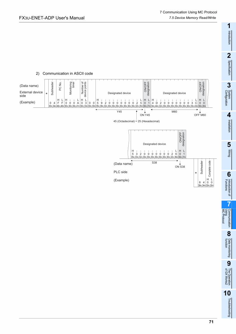
7 Communication Using MC Protocol
71
FX3U-ENET-ADP User's Manual
1
Introduction
2
Specification
3
System
C
onfiguration
4
Installation
5
Wiring
6
Introduction of F
unctions
7
Com
munication
Using
MC
Protocol
8
Data m
onitoring function
9
The O
peration of G
X W
orks2
10
Troubleshooting
7.5 Device Memory Read/Write
2) Communication in ASCII code
(Data name)
External deviceside
(Example)
Designated device
Y45
Designated device
M60
S38
ON Y45 OFF M60
ON S38
Designated device
939H
030H
434H
FH
46H
LF
46H
H0
30H
030H
030H
LA
41H
H0
30H
L3
33H
030H
030H
H5
35H
232H
030H
030H
030H
030H
030H
030H
030H
232H
L5
35H
H0
30H
L1
31H
H4
34H
D44H
232H
030H
030H
030H
030H
030H
030H
030H
333H
LC
43H
H0
30H
L0
30H
5H
35H
333H
232H
030H
030H
030H
030H
030H
030H
030H
232H
L6
36H
H0
30H
L1
31H
- - - - - - - - - -
434H
030H
030H38H
8LH
- - - - - - - - - - - - - - - - - - - - - -
Su
bh
ea
de
r
PC
No
.
Num
ber
of
devi
ce p
oin
ts
Mo
nito
rin
gtim
er
ON
/OF
Fd
esig
na
tio
n
ON
/OF
Fd
esig
na
tio
n
ON
/OF
Fd
esig
na
tio
n
(Data name)
PLC side
(Example)
Su
bh
ea
de
r
Com
plet
e co
de
45 (Octadecimal) = 25 (Hexadecimal)
*
*
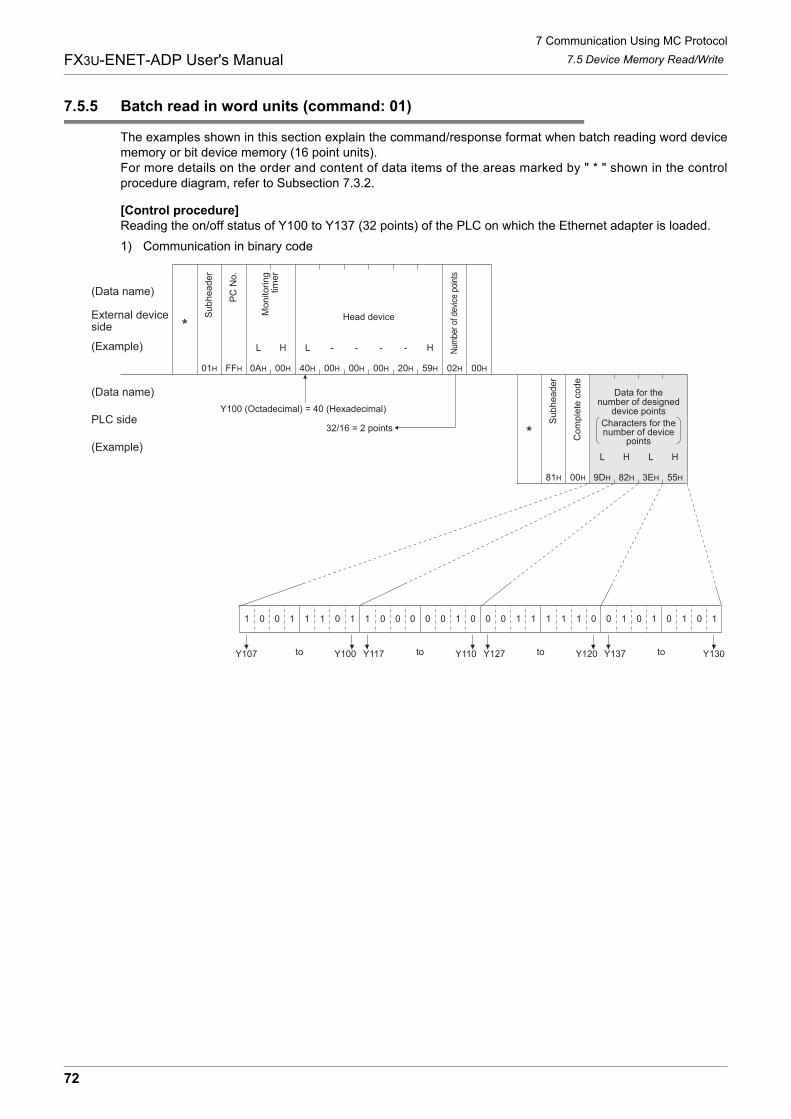
7 Communication Using MC Protocol
72
FX3U-ENET-ADP User's Manual 7.5 Device Memory Read/Write
7.5.5 Batch read in word units (command: 01)
The examples shown in this section explain the command/response format when batch reading word devicememory or bit device memory (16 point units).For more details on the order and content of data items of the areas marked by " * " shown in the controlprocedure diagram, refer to Subsection 7.3.2.
[Control procedure]Reading the on/off status of Y100 to Y137 (32 points) of the PLC on which the Ethernet adapter is loaded.
1) Communication in binary code
H
0AH 00H 00H40H 00H 00H 20H 59H 02H 00H
L L H
01 11 01 00 00 01 00 11 11 01 10 10 10 10
Y130Y137Y120Y127Y110Y117Y100
00H 9DH 82H 3EH 55H
L H L H
10 10
01H FFH
81H
Y107
- - - -
(Data name)
External deviceside
(Example)
(Data name)
PLC side
(Example)
Su
bh
ea
de
r
PC
No
.
Num
ber
of d
evic
e po
ints
Head deviceMo
nito
rin
gtim
er
Su
bh
ea
de
r
Co
mp
lete
co
de
Data for thenumber of designed
device points
Characters for thenumber of device
points
totototo
Y100 (Octadecimal) = 40 (Hexadecimal)
32/16 = 2 points *
*
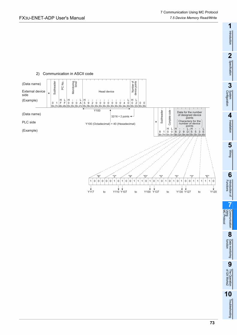
7 Communication Using MC Protocol
73
FX3U-ENET-ADP User's Manual
1
Introduction
2
Specification
3
System
C
onfiguration
4
Installation
5
Wiring
6
Introduction of F
unctions
7
Com
munication
Using
MC
Protocol
8
Data m
onitoring function
9
The O
peration of G
X W
orks2
10
Troubleshooting
7.5 Device Memory Read/Write
2) Communication in ASCII code
30H
38H
30H
0
31H
41H 35H
Y100
32/16 = 2 points
31H
146H
FH L
F46H
0H L
0 0 A 530H 30H 39H
932H
230H
030H
030H
030H
030H
030H
030H
0H L
34H
430H
0H
30H
0L
32H
230H
030H
0
8H
1 030H
L0
30H
H L8
38H
232H
939H
D44H
535H
333H
E45H
H L5
35H
"8" "2" "9" "D" "5" "5" "3" "E"
1 0 0 0 0 0 1 0 1 0 0 1 1 1 0 1 0 1 0 1 0 1 0 1 0 0 1 1 1 1 1 0
Y120Y127Y110Y117 Y130Y137Y100Y107
- - - - - - - - - - - -
- - - -
(Data name)
External deviceside
(Example)
(Data name)
PLC side
(Example)
Su
bh
ea
de
r
PC
No
.
Num
ber
ofde
vice
poi
nts
Head device
Mo
nito
rin
gtim
er
Su
bh
ea
de
r
Com
plet
e co
de Data for the numberof designed device
pointsCharacters for thenumber of device
points
to to to to
Y100 (Octadecimal) = 40 (Hexadecimal) *
*
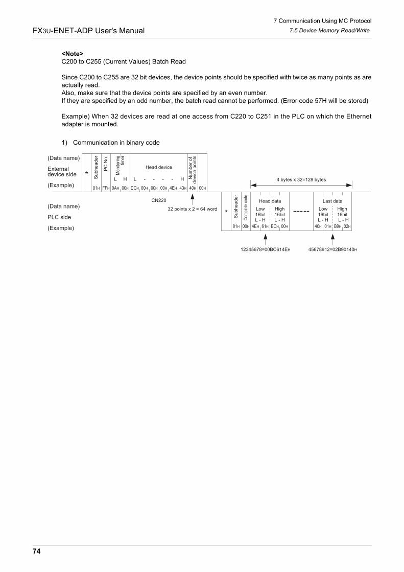
7 Communication Using MC Protocol
74
FX3U-ENET-ADP User's Manual 7.5 Device Memory Read/Write
<Note>C200 to C255 (Current Values) Batch Read
Since C200 to C255 are 32 bit devices, the device points should be specified with twice as many points as areactually read.Also, make sure that the device points are specified by an even number.If they are specified by an odd number, the batch read cannot be performed. (Error code 57H will be stored)
Example) When 32 devices are read at one access from C220 to C251 in the PLC on which the Ethernetadapter is mounted.
1) Communication in binary code
01H FFH
L
0AH
H
00H
81H 00H
43H4EHDCH 00H 00H 00H 40H 00H
4EH 61H BCH 00H 40H 01H B9H 02H
12345678=00BC614EH 45678912=02B90140H
CN220
Low16bit
High16bit
Low16bit
High16bit
L - H L - H L - HL - H
L - - - - H
(Data name)
External device side
(Example)
(Data name)
PLC side
(Example)
PC
No.
Subheader
4 bytes x 32=128 bytes
Mon
itorin
gtim
er
Head device
Num
ber
of
devic
e p
oin
ts
Head data
Subheader
Last data
Com
plet
e co
de
32 points x 2 = 64 word*
*
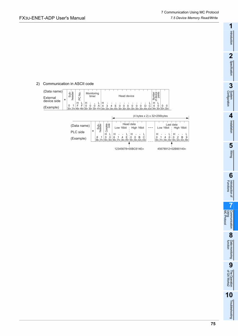
7 Communication Using MC Protocol
75
FX3U-ENET-ADP User's Manual
1
Introduction
2
Specification
3
System
C
onfiguration
4
Installation
5
Wiring
6
Introduction of F
unctions
7
Com
munication
Using
MC
Protocol
8
Data m
onitoring function
9
The O
peration of G
X W
orks2
10
Troubleshooting
7.5 Device Memory Read/Write
2) Communication in ASCII code
030H
HF
46H
131H
LF
46H
H0
30H
-0
30H
-0
30H
L LA
41H
838H
131H
L0
30H
H0
30H
34H 33H 34H 45H 30H 30H 30H 30H 30H 30H 44H 43H
12345678=00BC614EH 45678912=02B90140H
36H 31H 34H 45H 30H 30H 42H 43H 30H 31H 34H 30H 30H 32H 42H 39H
4 0 0 0H
34H 30H 30H 30H
4 3 4 E 0 0 0 0 0 0 D CH - - - - - - - - - - L
6 1 4 E 0 0 B CH - - L H - - L
0 1 4 0 0 2 B 9H - - L H - - L
(Data name)
Externaldevice side
(Example)
(Data name)
PLC side
(Example)
Last data
(4 bytes x 2) x 32=256bytes
MonitoringtimerS
ub
-h
ea
de
r
PC
No.
Head device
Num
ber
of d
evic
epo
ints
Sub-
header
Com
plet
eco
de Head data
Low 16bit High 16bit Low 16bit High 16bit
*
*
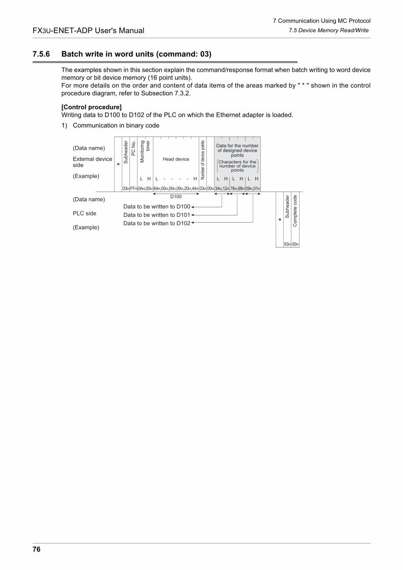
7 Communication Using MC Protocol
76
FX3U-ENET-ADP User's Manual 7.5 Device Memory Read/Write
7.5.6 Batch write in word units (command: 03)
The examples shown in this section explain the command/response format when batch writing to word devicememory or bit device memory (16 point units).For more details on the order and content of data items of the areas marked by " * " shown in the controlprocedure diagram, refer to Subsection 7.3.2.
[Control procedure]Writing data to D100 to D102 of the PLC on which the Ethernet adapter is loaded.
1) Communication in binary code
03H FFH 0AH
L
00H
H
64H 00H 20H 44H 03H 00H 34H 12H 76H 98H 09H 01H
L H
00H 00H
HL HL HL
83H 00H
Data to be written to D100
Data to be written to D101
Data to be written to D102
D100
- - - -
(Data name)
External deviceside
(Example)
(Data name)
PLC side
(Example)
Su
bh
ea
de
r
PC
No
.
Num
ber o
f dev
ice
poin
ts
Head deviceMo
nito
rin
gtim
er
Data for the numberof designed device
points
Characters for thenumber of device
points
Su
bh
ea
de
r
Co
mp
lete
co
de
*
*
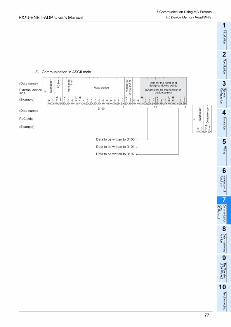
7 Communication Using MC Protocol
77
FX3U-ENET-ADP User's Manual
1
Introduction
2
Specification
3
System
C
onfiguration
4
Installation
5
Wiring
6
Introduction of F
unctions
7
Com
munication
Using
MC
Protocol
8
Data m
onitoring function
9
The O
peration of G
X W
orks2
10
Troubleshooting
7.5 Device Memory Read/Write
2) Communication in ASCII code
F30H
0
38H
D100
33H
346H 46H 30H
030H
030H
041H
A34H
434H
432H
230H
030H
030H
030H
030H
030H
030H
036H
634H
430H
033H
330H
030H
031H
132H
233H
334H
439H
938H
837H
736H
630H
031H
130H
039H
9FH L H L H L H L
833H
330H
030H
0
Data to be written to D100
Data to be written to D101
Data to be written to D102
- - - - - - - - - - - - H L- - H L- - H L- -
H L
(Data name)
External deviceside
(Example)
(Data name)
PLC side
(Example)
Su
bh
ea
de
r
PC
No
.
Nu
mb
er
of
de
vic
e p
oin
ts
Head device
Mo
nito
rin
gtim
er
Data for the number ofdesigned device points
(Characters for the number of device points)
Su
bh
ea
de
r
Com
plet
e co
de
*
*
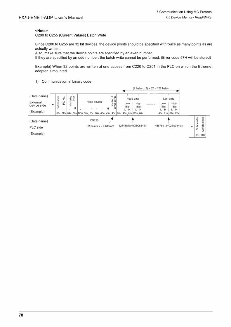
7 Communication Using MC Protocol
78
FX3U-ENET-ADP User's Manual 7.5 Device Memory Read/Write
<Note>C200 to C255 (Current Values) Batch Write
Since C200 to C255 are 32 bit devices, the device points should be specified with twice as many points as areactually written.Also, make sure that the device points are specified by an even number.If they are specified by an odd number, the batch write cannot be performed. (Error code 57H will be stored)
Example) When 32 points are written at one access from C220 to C251 in the PLC on which the Ethernetadapter is mounted.
1) Communication in binary code
03H FFH
L
0AH
H
00H
83H 00H
43H4EHDCH 00H 00H 00H 40H 00H 40H 01H B9H 02H
12345678=00BC614EH 45678912=02B90140H
CN220
4EH 61H BCH 00H
L - H L - HL - H L - HL - - - - H
(2 bytes x 2) x 32 = 128 bytes
(Data name)
Externaldevice side
(Example)
(Data name)
PLC side
(Example)
Com
plet
e co
de
Su
bh
ea
de
r
PC
No
.
Mon
itorin
gtim
er
Head device
Num
ber
ofde
vice
poi
nts
Su
bh
ea
de
r
Low16bit
High16bit
Low16bit
High16bit
Head data Last data
32 points x 2 = 64word
*
*
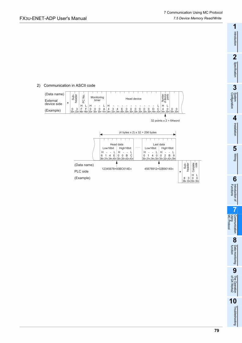
7 Communication Using MC Protocol
79
FX3U-ENET-ADP User's Manual
1
Introduction
2
Specification
3
System
C
onfiguration
4
Installation
5
Wiring
6
Introduction of F
unctions
7
Com
munication
Using
MC
Protocol
8
Data m
onitoring function
9
The O
peration of G
X W
orks2
10
Troubleshooting
7.5 Device Memory Read/Write
2) Communication in ASCII code
030H
HF
46H3
33H
LF
46H
H0
30H
-0
30H
-0
30H
LA
41H 34H 33H 34H 45H 30H 30H 30H 30H 30H 30H 44H 43H
H4
34H 30H00 0
30H 30H
H - - - - - - - - - - L4 3 4 E 0 0 0 0 0 0 D C
32 points x 2 = 64word
(Data name)
Externaldevice side
(Example)
(Data name)
PLC side
(Example)
Su
b-
he
ad
er
PC
No
.
Monitoringtimer
Head device
Num
ber
of d
evic
epo
ints
838H
333H
L0
30H
H0
30H
12345678=00BC614EH 45678912=02B90140H
36H 31H 34H 45H 30H 30H 42H 43H 30H 31H 34H 30H 30H 32H 42H 39H
6 1 4 E 0 0 B C 0 1 4 0 0 2 B 9H - - L H - - L H - - L H - - L
High16bitLow16bitHigh16bitLow16bit
Com
plet
eco
de
(4 bytes x 2) x 32 = 256 bytes
Head data Last data
Su
b-
header
L*
*
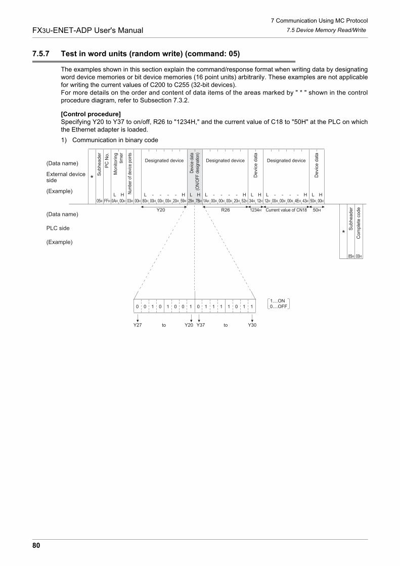
7 Communication Using MC Protocol
80
FX3U-ENET-ADP User's Manual 7.5 Device Memory Read/Write
7.5.7 Test in word units (random write) (command: 05)
The examples shown in this section explain the command/response format when writing data by designatingword device memories or bit device memories (16 point units) arbitrarily. These examples are not applicablefor writing the current values of C200 to C255 (32-bit devices).For more details on the order and content of data items of the areas marked by " * " shown in the controlprocedure diagram, refer to Subsection 7.3.2.
[Control procedure]Specifying Y20 to Y37 to on/off, R26 to "1234H," and the current value of C18 to "50H" at the PLC on whichthe Ethernet adapter is loaded.
1) Communication in binary code
Current value of CN18 50H1234H
Y30Y37Y20Y27
0 0 1 0 1 0 0 1 0 1 1 1 1 0 1 1
Y20 R26
1....ON0....OFF
05H FFH 0AH 03H 00H 80H 00H 00H 00H 20H 59H 29H 7BH 1AH 00H 00H 00H 20H 52H 34H 12H 12H 00H 00H 00H 4EH 43H 50H 00H
00H85H
00H
L L - H LH - - - H L - H L- - - H L - H L- - - H
(Data name)
External deviceside
(Example)
(Data name)
PLC side
(Example)
Su
bh
ea
de
r
PC
No
.
Num
ber
of d
evic
e po
ints
Mo
nito
rin
gtim
er
Designated device
Su
bh
ea
de
r
Co
mp
lete
co
de
to to
Designated device Designated device
Dev
ice
data
(ON
/OFF
des
igna
tion)
De
vic
e d
ata
De
vic
e d
ata
*
*
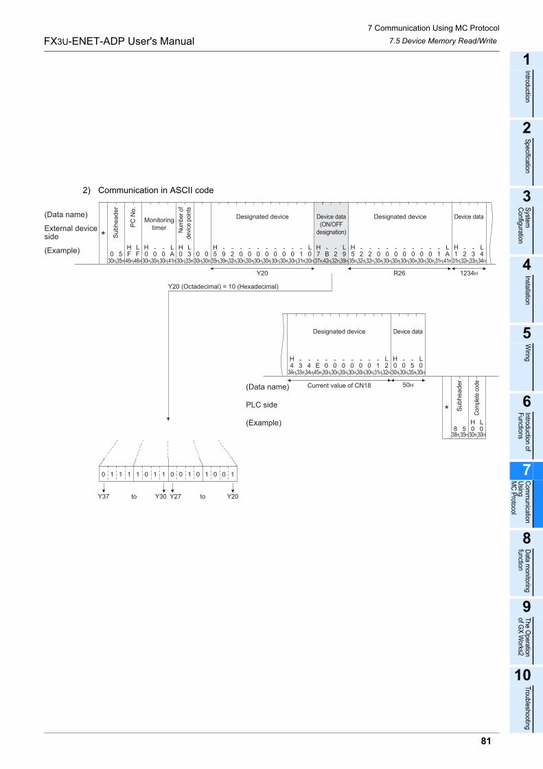
7 Communication Using MC Protocol
81
FX3U-ENET-ADP User's Manual
1
Introduction
2
Specification
3
System
C
onfiguration
4
Installation
5
Wiring
6
Introduction of F
unctions
7
Com
munication
Using
MC
Protocol
8
Data m
onitoring function
9
The O
peration of G
X W
orks2
10
Troubleshooting
7.5 Device Memory Read/Write
2) Communication in ASCII code
Y20
30H 35H 46H 46H 30H 30H 30H 41H 30H 33H 30H 30H 35H 39H 32H 30H 31H 30H 37H 42H 32H 39H 35H 32H 32H 30H 31H 41H
34H 33H 34H 45H 30H 30H 30H 30H 30H 30H 31H 32H 30H 30H
38H 35H 30H 30H
Designated device
R26
Current value of CN18
1234H
50H
31H 32H 33H 34H
35H 30H
0 1 1 1 1 0 1 1 0 0 1 0 1 0 0 1
Y20Y27Y30Y37
H L H - - L
30H30H 30H30H30H30H 30H 30H 30H 30H 30H 30H
0 5 F F 0 0 0 A 0 3 0 0 5 9 2 0 1 0 7 B 2 9 5 2 2 0 1 A 1 2 3 400 0000 0 0 0 0 0 0H L H - - L- - - - - - - - H - - L H - - L- - - - - - - - H - - L
H - L H L4 3 4 E 0 0 0 0 0 0 1 2 0 0 5 0
- - - - - - - - - - -
H L8 5 0 0
(Data name)
External deviceside
(Example)
Su
bh
ea
de
r
PC
No
.
Num
ber
ofde
vice
poi
nts
Monitoringtimer
(Data name)
PLC side
(Example)
Su
bh
ea
de
r
Com
plet
e co
de
to to
Y20 (Octadecimal) = 10 (Hexadecimal)
Designated device Device dataDevice data(ON/OFF
designation)
Device dataDesignated device
*
*
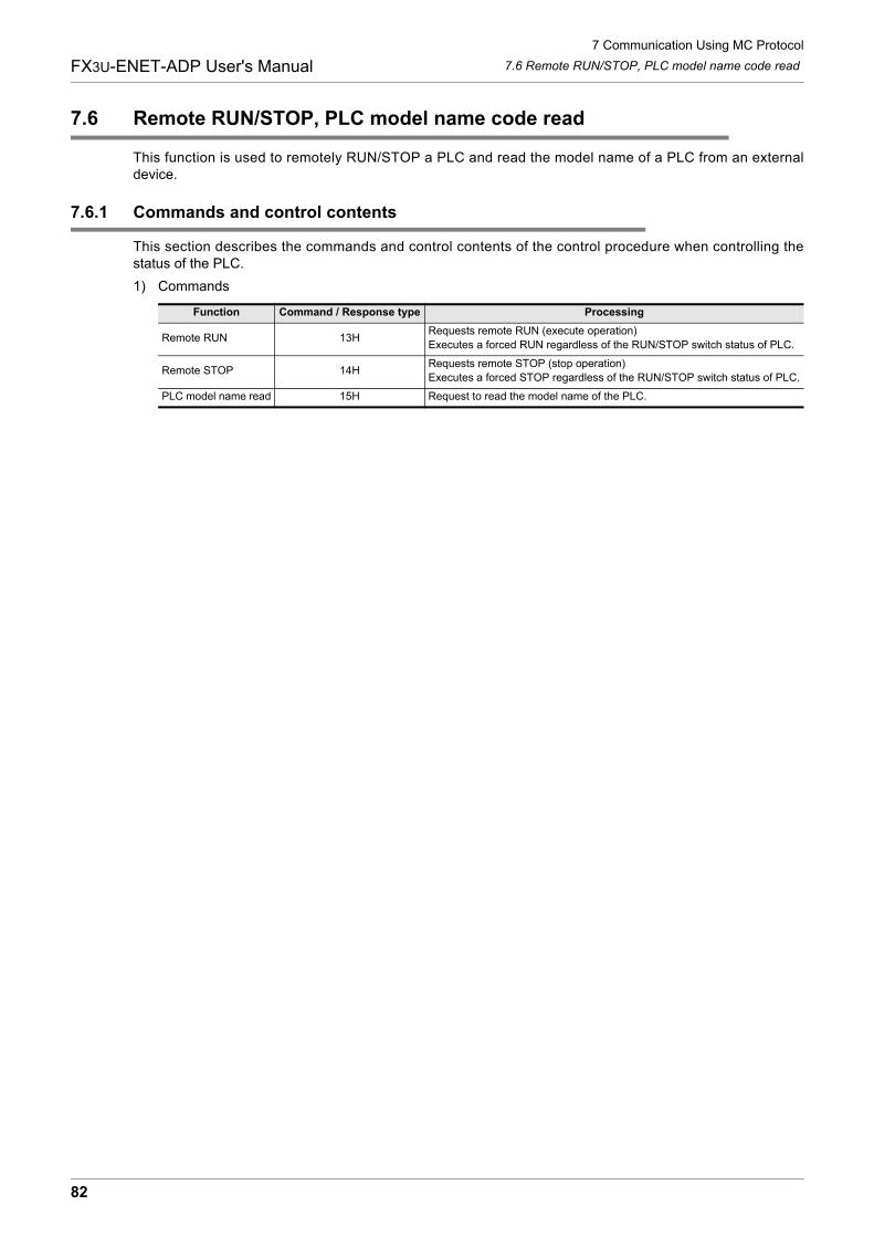
7 Communication Using MC Protocol
82
FX3U-ENET-ADP User's Manual 7.6 Remote RUN/STOP, PLC model name code read
7.6 Remote RUN/STOP, PLC model name code read
This function is used to remotely RUN/STOP a PLC and read the model name of a PLC from an externaldevice.
7.6.1 Commands and control contents
This section describes the commands and control contents of the control procedure when controlling thestatus of the PLC.
1) Commands
Function Command / Response type Processing
Remote RUN 13HRequests remote RUN (execute operation)
Executes a forced RUN regardless of the RUN/STOP switch status of PLC.
Remote STOP 14HRequests remote STOP (stop operation)
Executes a forced STOP regardless of the RUN/STOP switch status of PLC.
PLC model name read 15H Request to read the model name of the PLC.
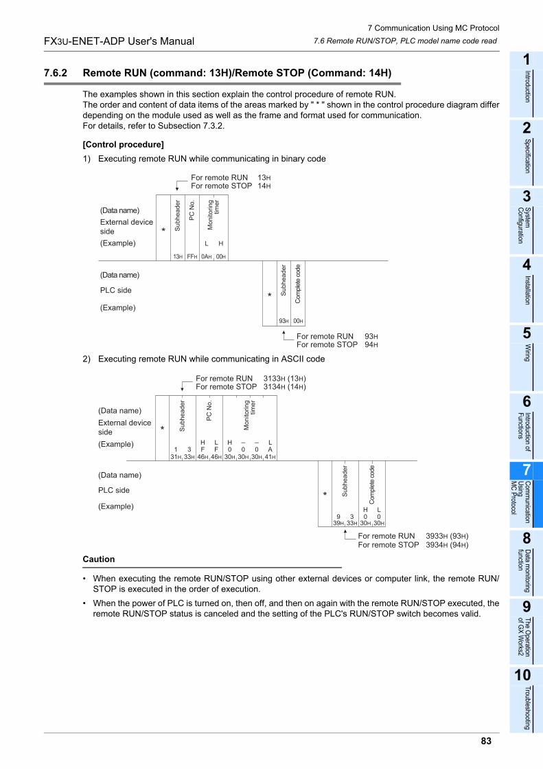
7 Communication Using MC Protocol
83
FX3U-ENET-ADP User's Manual
1
Introduction
2
Specification
3
System
C
onfiguration
4
Installation
5
Wiring
6
Introduction of F
unctions
7
Com
munication
Using
MC
Protocol
8
Data m
onitoring function
9
The O
peration of G
X W
orks2
10
Troubleshooting
7.6 Remote RUN/STOP, PLC model name code read
7.6.2 Remote RUN (command: 13H)/Remote STOP (Command: 14H)
The examples shown in this section explain the control procedure of remote RUN.The order and content of data items of the areas marked by " * " shown in the control procedure diagram differdepending on the module used as well as the frame and format used for communication.For details, refer to Subsection 7.3.2.
[Control procedure]
1) Executing remote RUN while communicating in binary code
2) Executing remote RUN while communicating in ASCII code
Caution
� When executing the remote RUN/STOP using other external devices or computer link, the remote RUN/STOP is executed in the order of execution.
� When the power of PLC is turned on, then off, and then on again with the remote RUN/STOP executed, theremote RUN/STOP status is canceled and the setting of the PLC's RUN/STOP switch becomes valid.
(Data name)
93H
FFH 0AH 00H
L H
13H
00H
External deviceside
(Example)
(Data name)
(Example)
PLC side
Su
bh
ea
de
r
PC
No
.
Mo
nito
rin
gtim
er
Com
ple
te c
ode
Su
bh
ea
de
r
For remote STOP 14H
For remote RUN 13H
For remote STOPFor remote RUN
94H
93H
*
*
F31H
133H
346H 46H 30H
030H
030H
041H
AFH L H L
39H
933H
330H
030H
0H L
(Data name)
External deviceside
(Example)
(Data name)
(Example)
PLC side
Su
bh
ea
de
r
PC
No
.
Mo
nito
rin
gtim
er
Com
ple
te c
ode
Su
bh
ea
de
r
For remote RUNFor remote STOP
3933H (93H)3934H (94H)
For remote RUNFor remote STOP
3133H (13H)3134H (14H)
*
*
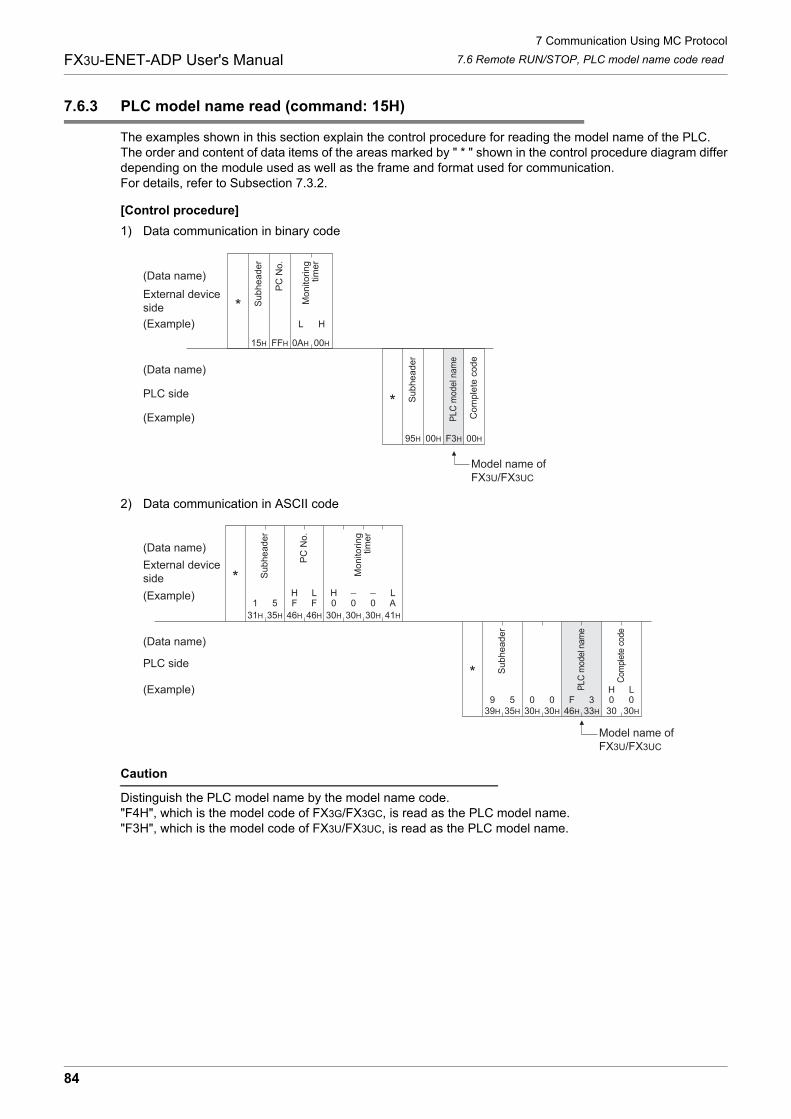
7 Communication Using MC Protocol
84
FX3U-ENET-ADP User's Manual 7.6 Remote RUN/STOP, PLC model name code read
7.6.3 PLC model name read (command: 15H)
The examples shown in this section explain the control procedure for reading the model name of the PLC.The order and content of data items of the areas marked by " * " shown in the control procedure diagram differdepending on the module used as well as the frame and format used for communication.For details, refer to Subsection 7.3.2.
[Control procedure]
1) Data communication in binary code
2) Data communication in ASCII code
Caution
Distinguish the PLC model name by the model name code."F4H", which is the model code of FX3G/FX3GC, is read as the PLC model name."F3H", which is the model code of FX3U/FX3UC, is read as the PLC model name.
(Data name)
External deviceside
(Example)
(Data name)
(Example)
PLC side
Su
bh
ea
de
r
PC
No
.
Mo
nito
rin
gtim
er
Co
mp
lete
co
de
Su
bh
ea
de
r
FFH 0AH 00H
L H
95H
15H
00H F3H 00H
PLC
model n
am
e
Model name of FX3U/FX3UC
*
*
(Data name)
F
31H
1
35H
5
46H 46H 30H
0
30H
0
30H
0
41H
AFH L H L
39H
935H
530H
030H
046H
F33H
3300
30H
0H L
External deviceside
(Example)
(Data name)
(Example)
PLC side
Su
bh
ea
de
r
PC
No
.
Mo
nito
rin
gtim
er
Com
plet
e co
de
Su
bh
ea
de
r
PLC
mod
el n
ame
Model name of FX3U/FX3UC
*
*

7 Communication Using MC Protocol
85
FX3U-ENET-ADP User's Manual
1
Introduction
2
Specification
3
System
C
onfiguration
4
Installation
5
Wiring
6
Introduction of F
unctions
7
Com
munication
Using
MC
Protocol
8
Data m
onitoring function
9
The O
peration of G
X W
orks2
10
Troubleshooting
7.6 Remote RUN/STOP, PLC model name code read
MEMO
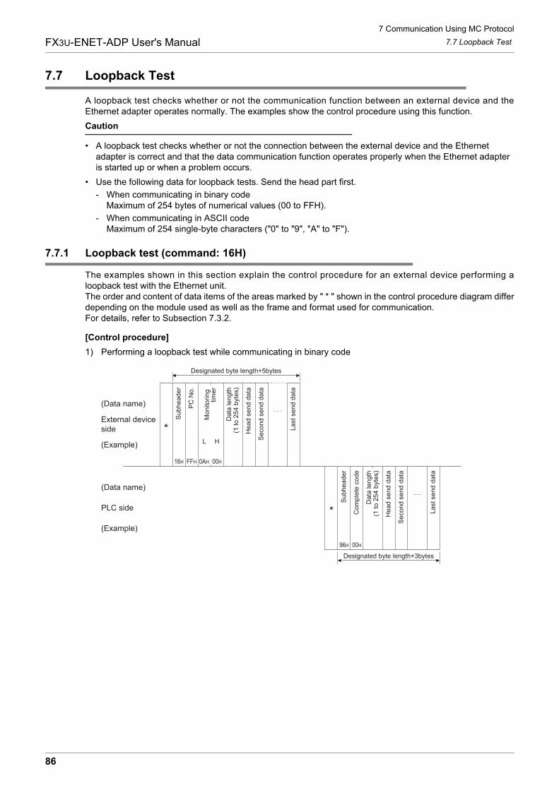
7 Communication Using MC Protocol
86
FX3U-ENET-ADP User's Manual 7.7 Loopback Test
7.7 Loopback Test
A loopback test checks whether or not the communication function between an external device and theEthernet adapter operates normally. The examples show the control procedure using this function.
Caution
� A loopback test checks whether or not the connection between the external device and the Ethernet adapter is correct and that the data communication function operates properly when the Ethernet adapter is started up or when a problem occurs.
� Use the following data for loopback tests. Send the head part first.
- When communicating in binary code Maximum of 254 bytes of numerical values (00 to FFH).
- When communicating in ASCII code Maximum of 254 single-byte characters ("0" to "9", "A" to "F").
7.7.1 Loopback test (command: 16H)
The examples shown in this section explain the control procedure for an external device performing aloopback test with the Ethernet unit.The order and content of data items of the areas marked by " * " shown in the control procedure diagram differdepending on the module used as well as the frame and format used for communication.For details, refer to Subsection 7.3.2.
[Control procedure]
1) Performing a loopback test while communicating in binary code
(Data name)
External deviceside
(Example)
(Data name)
(Example)
PLC side
Su
bh
ea
de
r
PC
No
.
Mo
nito
rin
g
tim
er
Co
mp
lete
co
de
Su
bh
ea
de
r
16H FFH 0AH 00H
L H
96H 00H
Da
ta le
ng
th(1
to
25
4 b
yte
s)
He
ad
se
nd
da
ta
Se
co
nd
se
nd
da
ta
La
st
se
nd
da
ta
Da
ta le
ng
th(1
to
25
4 b
yte
s)
He
ad
se
nd
da
ta
Se
co
nd
se
nd
da
ta
La
st
se
nd
da
ta
Designated byte length+5bytes
Designated byte length+3bytes
*
*
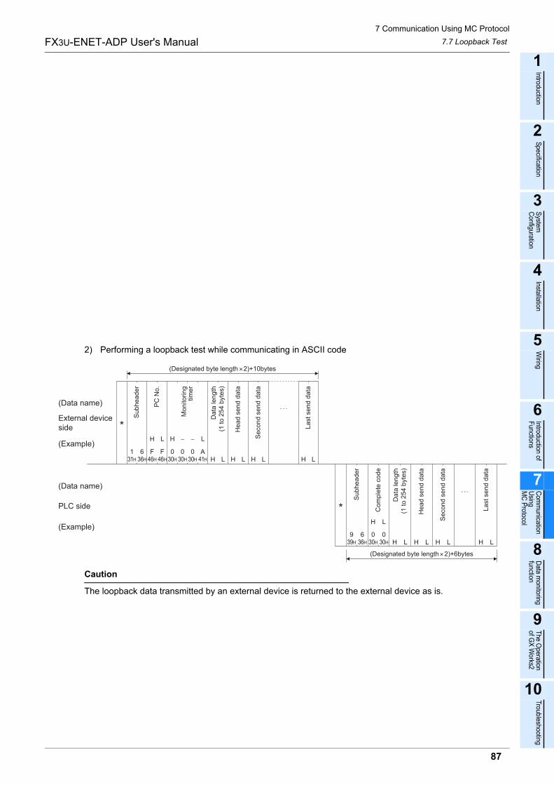
7 Communication Using MC Protocol
87
FX3U-ENET-ADP User's Manual
1
Introduction
2
Specification
3
System
C
onfiguration
4
Installation
5
Wiring
6
Introduction of F
unctions
7
Com
munication
Using
MC
Protocol
8
Data m
onitoring function
9
The O
peration of G
X W
orks2
10
Troubleshooting
7.7 Loopback Test
2) Performing a loopback test while communicating in ASCII code
Caution
The loopback data transmitted by an external device is returned to the external device as is.
31H 36H 46H 46H 30H 30H 30H 41H
6
H
F
L
F1
H
0 0
L
A0LHLHLHLH
39H 36H 30H 30H
6
H
0
L
09LHLHLHLH
(Data name)
External deviceside
(Example)
(Data name)
(Example)
PLC side
Su
bh
ea
de
r
PC
No
.
Mo
nito
rin
gtim
er
Co
mp
lete
co
de
Su
bh
ea
de
r
Da
ta le
ng
th(1
to
25
4 b
yte
s)
He
ad
se
nd
da
ta
Se
co
nd
se
nd
da
ta
La
st
se
nd
da
ta
Da
ta le
ng
th(1
to
25
4 b
yte
s)
He
ad
se
nd
da
ta
Se
co
nd
se
nd
da
ta
La
st
se
nd
da
ta
(Designated byte length 2)+10bytes
(Designated byte length 2)+6bytes
*
*
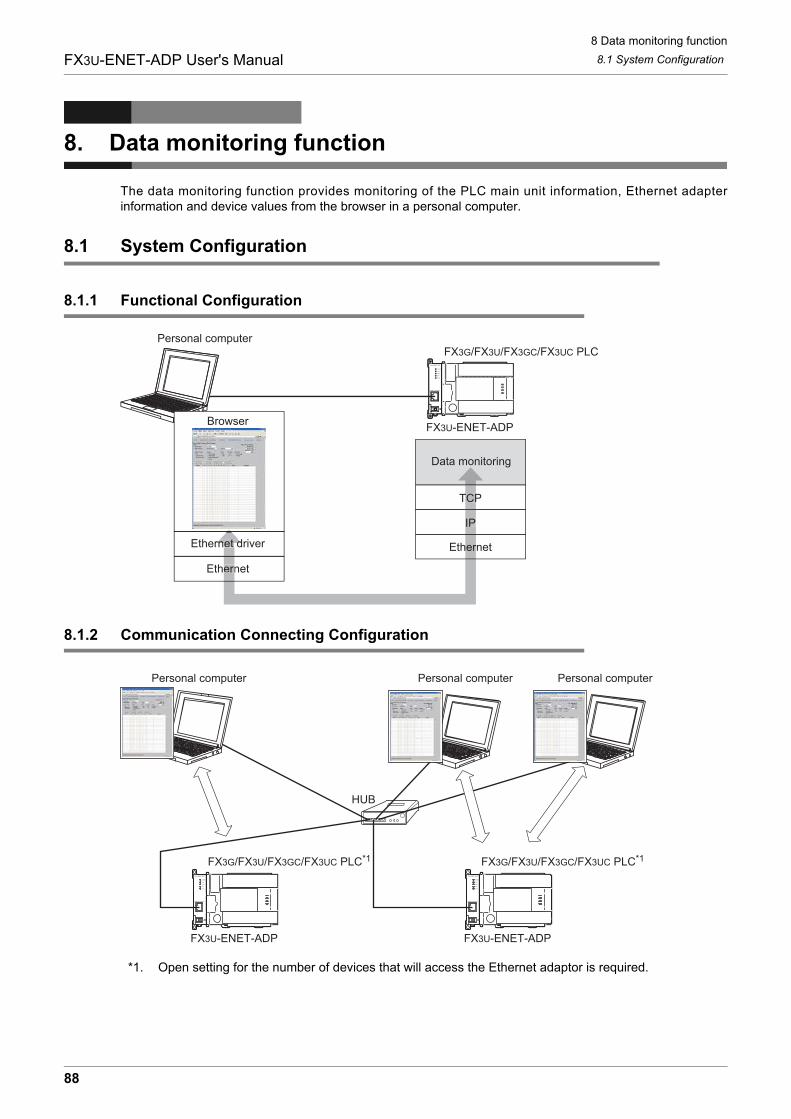
8 Data monitoring function
8.1 System Configuration
88
FX3U-ENET-ADP User's Manual
8. Data monitoring function
The data monitoring function provides monitoring of the PLC main unit information, Ethernet adapterinformation and device values from the browser in a personal computer.
8.1 System Configuration
8.1.1 Functional Configuration
8.1.2 Communication Connecting Configuration
*1. Open setting for the number of devices that will access the Ethernet adaptor is required.
FX3G/FX3U/FX3GC/FX3UC PLCPersonal computer
FX3U-ENET-ADP
Ethernet
IP
TCP
Data monitoring
Browser
Ethernet driver
ern
IP
TCP
rnet d Ethernet
FX3G/FX3U/FX3GC/FX3UC PLC*1 FX3G/FX3U/FX3GC/FX3UC PLC*1
FX3U-ENET-ADP FX3U-ENET-ADP
HUB
Personal computer Personal computer Personal computer
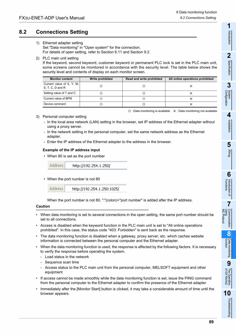
8 Data monitoring function
8.2 Connections Setting
89
FX3U-ENET-ADP User's Manual
1
Introduction
2
Specification
3
System
C
onfiguration
4
Installation
5
Wiring
6
Introduction of F
unctions
7
Com
munication
Using
MC
Protocol
8
Data m
onitoring function
9
The O
peration of G
X W
orks2
10
Troubleshooting
8.2 Connections Setting
1) Ethernet adapter settingSet "Data monitoring" in "Open system" for the connection.For details of open setting, refer to Section 6.11 and Section 9.2.
2) PLC main unit settingIf the keyword, second keyword, customer keyword or permanent PLC lock is set in the PLC main unit,some screens cannot be monitored in accordance with the security level. The table below shows thesecurity level and contents of display on each monitor screen.
: Data monitoring is available : Data monitoring not available
3) Personal computer setting
- In the local area network (LAN) setting in the browser, set IP address of the Ethernet adapter without using a proxy server.
- In the network setting in the personal computer, set the same network address as the Ethernet adapter.
- Enter the IP address of the Ethernet adapter to the address in the browser.
Example of the IP address input
� When 80 is set as the port number
� When the port number is not 80
When the port number is not 80, ":"(colon)+"port number" is added after the IP address.
Caution
� When data monitoring is set to several connections in the open setting, the same port number should be set to all connections.
� Access is disabled when the keyword function in the PLC main unit is set to "All online operations prohibited". In this case, the status code "403: Forbidden" is sent back as the response.
� The data monitoring function is disabled when a gateway, proxy server, etc. which caches website information is connected between the personal computer and the Ethernet adapter.
� When the data monitoring function is used, the response is affected by the following factors. It is necessary to verify the response before operating the system.
- Load status in the network
- Sequence scan time
- Access status to the PLC main unit from the personal computer, MELSOFT equipment and other equipment
� If access cannot be made smoothly while the data monitoring function is set, issue the PING command from the personal computer to the Ethernet adapter to confirm the presence of the Ethernet adapter.
� Immediately after the [Monitor Start] button is clicked, it may take a considerable amount of time until the browser appears.
Monitor content Write prohibited Read and write prohibited All online operations prohibited
Current value of X, Y, M,
S, T, C, D and R
Setting value of T and C
Current value of BFM
Device comment
8 Data monitoring function
8.3 Functions List
90
FX3U-ENET-ADP User's Manual
8.3 Functions List
The following contents can be monitored, and the language can be switched.
*1. In English display, device comments are displayed only when they are registered in ASCII characters.
*2. The Ethernet adapter Ver. 1.10 or later supports the switch language function.
8.4 Corresponding HTTP Version
*3. Browsers supporting HTTP/1.0 or HTTP/1.1.
Function Description
Device/Buffer Memory Batch
Monitor
� Device monitor
Device batch and Device comment*1 is monitored.
� Buffer Memory monitor
Buffer Memory batch and Device comment*1 is monitored.
PLC Information MonitorThe type, version, RUN/STOP status, error code, date and time and title information of the PLC main
unit are monitored.
FX3U-ENET-ADP Information
Monitor
The version, setting information (IP address, subnet mask and default router), connection information,
error history and LED status of the Ethernet adapter are monitored.
Communication Status MonitorThe operation status (IP address, subnet mask and default router), MAC address and send/receive
packet information are monitored.
Access Log Monitor The access information on up to 32 cases is monitored.
Switch Language*2 The language can be switched between Japanese and English.
Item Specification
HTTP versionHTTP/1.0, HTTP/1.1*3
(HTTP/0.9 is not supported.)
Session figure
(Connection figure)Number set for data monitoring in the open setting.
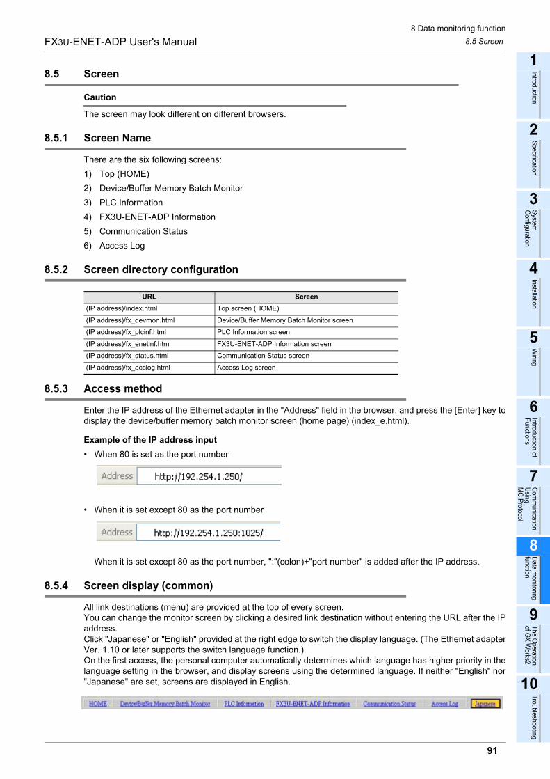
8 Data monitoring function
8.5 Screen
91
FX3U-ENET-ADP User's Manual
1
Introduction
2
Specification
3
System
C
onfiguration
4
Installation
5
Wiring
6
Introduction of F
unctions
7
Com
munication
Using
MC
Protocol
8
Data m
onitoring function
9
The O
peration of G
X W
orks2
10
Troubleshooting
8.5 Screen
Caution
The screen may look different on different browsers.
8.5.1 Screen Name
There are the six following screens:
1) Top (HOME)
2) Device/Buffer Memory Batch Monitor
3) PLC Information
4) FX3U-ENET-ADP Information
5) Communication Status
6) Access Log
8.5.2 Screen directory configuration
8.5.3 Access method
Enter the IP address of the Ethernet adapter in the "Address" field in the browser, and press the [Enter] key todisplay the device/buffer memory batch monitor screen (home page) (index_e.html).
Example of the IP address input
� When 80 is set as the port number
� When it is set except 80 as the port number
When it is set except 80 as the port number, ":"(colon)+"port number" is added after the IP address.
8.5.4 Screen display (common)
All link destinations (menu) are provided at the top of every screen.You can change the monitor screen by clicking a desired link destination without entering the URL after the IPaddress.Click "Japanese" or "English" provided at the right edge to switch the display language. (The Ethernet adapterVer. 1.10 or later supports the switch language function.)On the first access, the personal computer automatically determines which language has higher priority in thelanguage setting in the browser, and display screens using the determined language. If neither "English" nor"Japanese" are set, screens are displayed in English.
URL Screen
(IP address)/index.html Top screen (HOME)
(IP address)/fx_devmon.html Device/Buffer Memory Batch Monitor screen
(IP address)/fx_plcinf.html PLC Information screen
(IP address)/fx_enetinf.html FX3U-ENET-ADP Information screen
(IP address)/fx_status.html Communication Status screen
(IP address)/fx_acclog.html Access Log screen
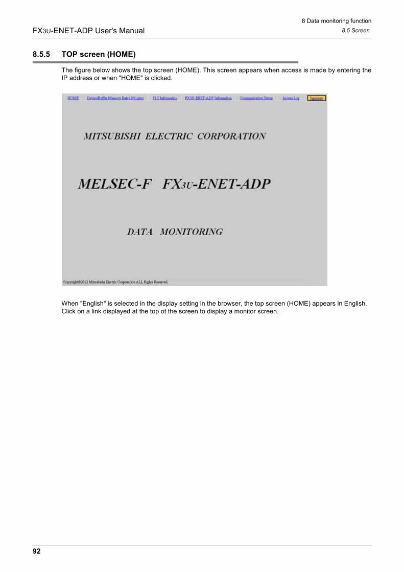
8 Data monitoring function
8.5 Screen
92
FX3U-ENET-ADP User's Manual
8.5.5 TOP screen (HOME)
The figure below shows the top screen (HOME). This screen appears when access is made by entering theIP address or when "HOME" is clicked.
When "English" is selected in the display setting in the browser, the top screen (HOME) appears in English.Click on a link displayed at the top of the screen to display a monitor screen.
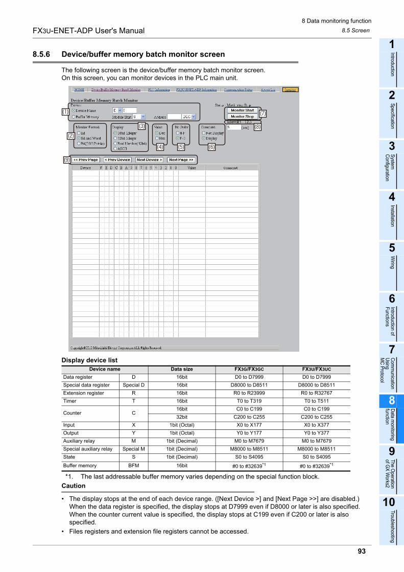
8 Data monitoring function
8.5 Screen
93
FX3U-ENET-ADP User's Manual
1
Introduction
2
Specification
3
System
C
onfiguration
4
Installation
5
Wiring
6
Introduction of F
unctions
7
Com
munication
Using
MC
Protocol
8
Data m
onitoring function
9
The O
peration of G
X W
orks2
10
Troubleshooting
8.5.6 Device/buffer memory batch monitor screen
The following screen is the device/buffer memory batch monitor screen.On this screen, you can monitor devices in the PLC main unit.
Display device list
*1. The last addressable buffer memory varies depending on the special function block.
Caution
� The display stops at the end of each device range. ([Next Device >] and [Next Page >>] are disabled.)When the data register is specified, the display stops at D7999 even if D8000 or later is also specified.When the counter current value is specified, the display stops at C199 even if C200 or later is also specified.
� Files registers and extension file registers cannot be accessed.
Device name Data size FX3G/FX3GC FX3U/FX3UC
Data register D 16bit D0 to D7999 D0 to D7999
Special data register Special D 16bit D8000 to D8511 D8000 to D8511
Extension register R 16bit R0 to R23999 R0 to R32767
Timer T 16bit T0 to T319 T0 to T511
Counter C16bit C0 to C199 C0 to C199
32bit C200 to C255 C200 to C255
Input X 1bit (Octal) X0 to X177 X0 to X377
Output Y 1bit (Octal) Y0 to Y177 Y0 to Y377
Auxiliary relay M 1bit (Decimal) M0 to M7679 M0 to M7679
Special auxiliary relay Special M 1bit (Decimal) M8000 to M8511 M8000 to M8511
State S 1bit (Decimal) S0 to S4095 S0 to S4095
Buffer memory BFM 16bit #0 to #32639*1 #0 to #32639*1
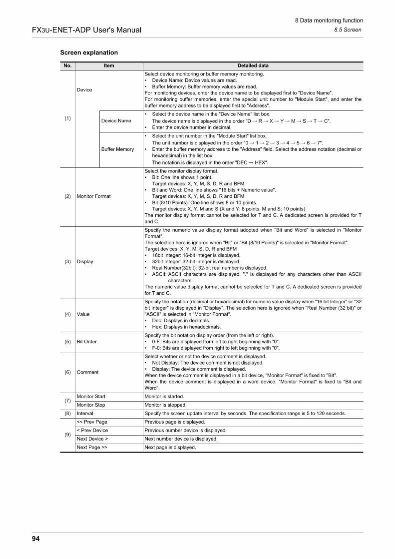
8 Data monitoring function
8.5 Screen
94
FX3U-ENET-ADP User's Manual
Screen explanation
No. Item Detailed data
(1)
Device
Select device monitoring or buffer memory monitoring.
� Device Name: Device values are read.
� Buffer Memory: Buffer memory values are read.
For monitoring devices, enter the device name to be displayed first to "Device Name".
For monitoring buffer memories, enter the special unit number to "Module Start", and enter the
buffer memory address to be displayed first to "Address".
Device Name
� Select the device name in the "Device Name" list box.
The device name is displayed in the order "D R X Y M S T C".
� Enter the device number in decimal.
Buffer Memory
� Select the unit number in the "Module Start" list box.
The unit number is displayed in the order "0 1 2 3 4 5 6 7".
� Enter the buffer memory address to the "Address" field. Select the address notation (decimal or
hexadecimal) in the list box.
The notation is displayed in the order "DEC HEX".
(2) Monitor Format
Select the monitor display format.
� Bit: One line shows 1 point.
Target devices: X, Y, M, S, D, R and BFM
� Bit and Word: One line shows "16 bits + Numeric value".
Target devices: X, Y, M, S, D, R and BFM
� Bit (8/10 Points): One line shows 8 or 10 points.
Target devices: X, Y, M and S (X and Y: 8 points, M and S: 10 points)
The monitor display format cannot be selected for T and C. A dedicated screen is provided for T
and C.
(3) Display
Specify the numeric value display format adopted when "Bit and Word" is selected in "Monitor
Format".
The selection here is ignored when "Bit" or "Bit (8/10 Points)" is selected in "Monitor Format".
Target devices: X, Y, M, S, D, R and BFM
� 16bit Integer: 16-bit integer is displayed.
� 32bit Integer: 32-bit integer is displayed.
� Real Number(32bit): 32-bit real number is displayed.
� ASCII: ASCII characters are displayed. "." is displayed for any characters other than ASCII
characters.
The numeric value display format cannot be selected for T and C. A dedicated screen is provided
for T and C.
(4) Value
Specify the notation (decimal or hexadecimal) for numeric value display when "16 bit Integer" or "32
bit Integer" is displayed in "Display". The selection here is ignored when "Real Number (32 bit)" or
"ASCII" is selected in "Monitor Format".
� Dec: Displays in decimals.
� Hex: Displays in hexadecimals.
(5) Bit Order
Specify the bit notation display order (from the left or right).
� 0-F: Bits are displayed from left to right beginning with "0".
� F-0: Bits are displayed from right to left beginning with "0".
(6) Comment
Select whether or not the device comment is displayed.
� Not Display: The device comment is not displayed.
� Display: The device comment is displayed.
When the device comment is displayed in a bit device, "Monitor Format" is fixed to "Bit".
When the device comment is displayed in a word device, "Monitor Format" is fixed to "Bit and
Word".
(7)Monitor Start Monitor is started.
Monitor Stop Monitor is stopped.
(8) Interval Specify the screen update interval by seconds. The specification range is 5 to 120 seconds.
(9)
<< Prev Page Previous page is displayed.
< Prev Device Previous number device is displayed.
Next Device > Next number device is displayed.
Next Page >> Next page is displayed.
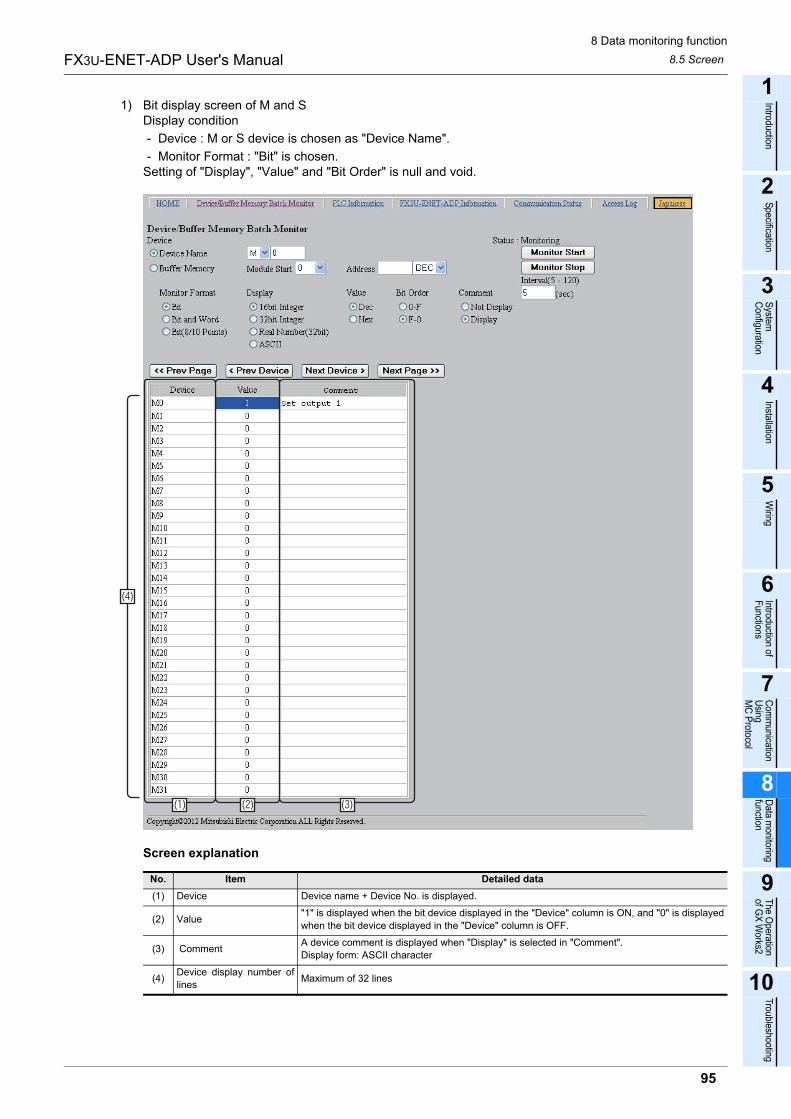
8 Data monitoring function
8.5 Screen
95
FX3U-ENET-ADP User's Manual
1
Introduction
2
Specification
3
System
C
onfiguration
4
Installation
5
Wiring
6
Introduction of F
unctions
7
Com
munication
Using
MC
Protocol
8
Data m
onitoring function
9
The O
peration of G
X W
orks2
10
Troubleshooting
1) Bit display screen of M and SDisplay condition
- Device : M or S device is chosen as "Device Name".
- Monitor Format : "Bit" is chosen.Setting of "Display", "Value" and "Bit Order" is null and void.
Screen explanation
No. Item Detailed data
(1) Device Device name + Device No. is displayed.
(2) Value"1" is displayed when the bit device displayed in the "Device" column is ON, and "0" is displayed
when the bit device displayed in the "Device" column is OFF.
(3) CommentA device comment is displayed when "Display" is selected in "Comment".
Display form: ASCII character
(4)Device display number of
linesMaximum of 32 lines
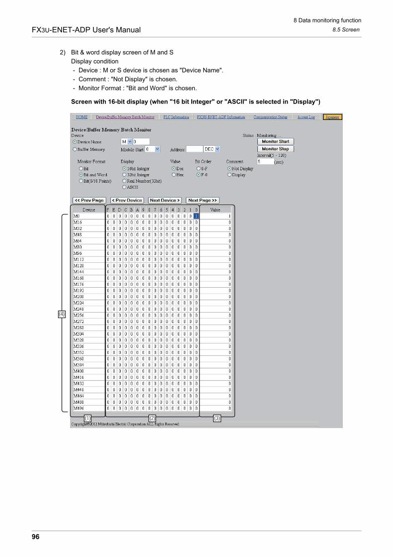
8 Data monitoring function
8.5 Screen
96
FX3U-ENET-ADP User's Manual
2) Bit & word display screen of M and S
Display condition
- Device : M or S device is chosen as "Device Name".
- Comment : "Not Display" is chosen.
- Monitor Format : "Bit and Word" is chosen.
Screen with 16-bit display (when "16 bit Integer" or "ASCII" is selected in "Display")
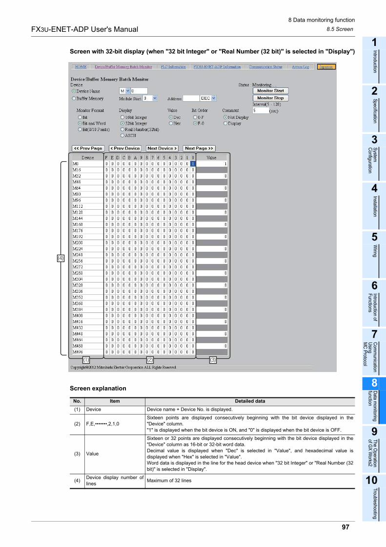
8 Data monitoring function
8.5 Screen
97
FX3U-ENET-ADP User's Manual
1
Introduction
2
Specification
3
System
C
onfiguration
4
Installation
5
Wiring
6
Introduction of F
unctions
7
Com
munication
Using
MC
Protocol
8
Data m
onitoring function
9
The O
peration of G
X W
orks2
10
Troubleshooting
Screen with 32-bit display (when "32 bit Integer" or "Real Number (32 bit)" is selected in "Display")
Screen explanation
No. Item Detailed data
(1) Device Device name + Device No. is displayed.
(2) F,E,�������,2,1,0
Sixteen points are displayed consecutively beginning with the bit device displayed in the
"Device" column.
"1" is displayed when the bit device is ON, and "0" is displayed when the bit device is OFF.
(3) Value
Sixteen or 32 points are displayed consecutively beginning with the bit device displayed in the
"Device" column as 16-bit or 32-bit word data.
Decimal value is displayed when "Dec" is selected in "Value", and hexadecimal value is
displayed when "Hex" is selected in "Value".
Word data is displayed in the line for the head device when "32 bit Integer" or "Real Number (32
bit)" is selected in "Display".
(4)Device display number of
linesMaximum of 32 lines
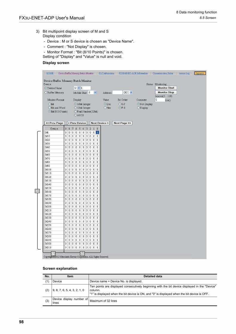
8 Data monitoring function
8.5 Screen
98
FX3U-ENET-ADP User's Manual
3) Bit multipoint display screen of M and SDisplay condition
- Device : M or S device is chosen as "Device Name".
- Comment : "Not Display" is chosen.
- Monitor Format : "Bit (8/10 Points)" is chosen.Setting of "Display" and "Value" is null and void.
Display screen
Screen explanation
No. Item Detailed data
(1) Device Device name + Device No. is displayed.
(2) 9, 8, 7, 6, 5, 4, 3, 2, 1, 0
Ten points are displayed consecutively beginning with the bit device displayed in the "Device"
column.
"1" is displayed when the bit device is ON, and "0" is displayed when the bit device is OFF.
(3)Device display number of
linesMaximum of 32 lines
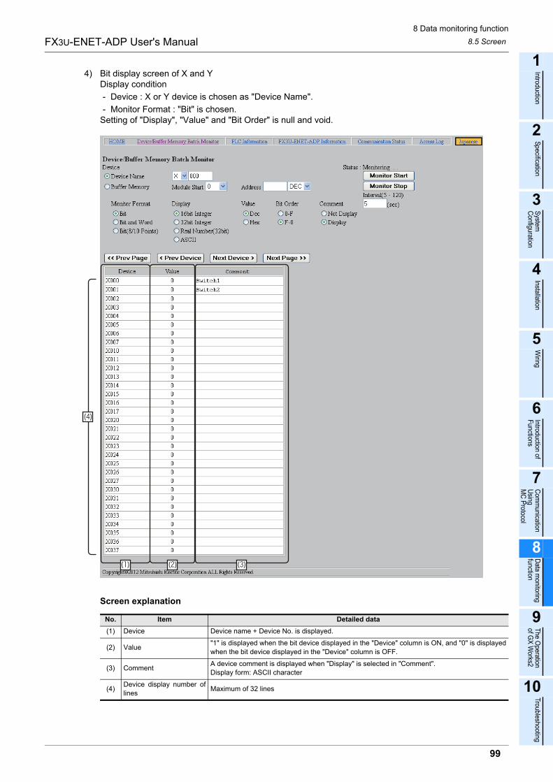
8 Data monitoring function
8.5 Screen
99
FX3U-ENET-ADP User's Manual
1
Introduction
2
Specification
3
System
C
onfiguration
4
Installation
5
Wiring
6
Introduction of F
unctions
7
Com
munication
Using
MC
Protocol
8
Data m
onitoring function
9
The O
peration of G
X W
orks2
10
Troubleshooting
4) Bit display screen of X and YDisplay condition
- Device : X or Y device is chosen as "Device Name".
- Monitor Format : "Bit" is chosen.Setting of "Display", "Value" and "Bit Order" is null and void.
Screen explanation
No. Item Detailed data
(1) Device Device name + Device No. is displayed.
(2) Value"1" is displayed when the bit device displayed in the "Device" column is ON, and "0" is displayed
when the bit device displayed in the "Device" column is OFF.
(3) CommentA device comment is displayed when "Display" is selected in "Comment".
Display form: ASCII character
(4)Device display number of
linesMaximum of 32 lines
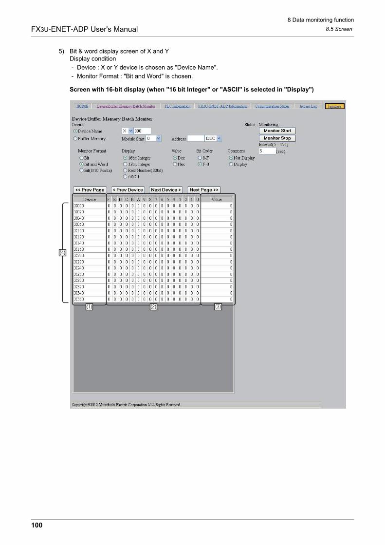
8 Data monitoring function
8.5 Screen
100
FX3U-ENET-ADP User's Manual
5) Bit & word display screen of X and YDisplay condition
- Device : X or Y device is chosen as "Device Name".
- Monitor Format : "Bit and Word" is chosen.
Screen with 16-bit display (when "16 bit Integer" or "ASCII" is selected in "Display")
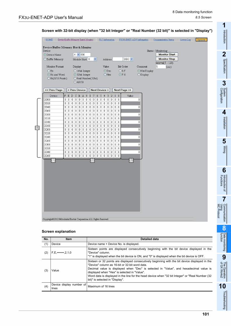
8 Data monitoring function
8.5 Screen
101
FX3U-ENET-ADP User's Manual
1
Introduction
2
Specification
3
System
C
onfiguration
4
Installation
5
Wiring
6
Introduction of F
unctions
7
Com
munication
Using
MC
Protocol
8
Data m
onitoring function
9
The O
peration of G
X W
orks2
10
Troubleshooting
Screen with 32-bit display (when "32 bit Integer" or "Real Number (32 bit)" is selected in "Display")
Screen explanation
No. Item Detailed data
(1) Device Device name + Device No. is displayed.
(2) F,E,�������,2,1,0
Sixteen points are displayed consecutively beginning with the bit device displayed in the
"Device" column.
"1" is displayed when the bit device is ON, and "0" is displayed when the bit device is OFF.
(3) Value
Sixteen or 32 points are displayed consecutively beginning with the bit device displayed in the
"Device" column as 16-bit or 32-bit word data.
Decimal value is displayed when "Dec" is selected in "Value", and hexadecimal value is
displayed when "Hex" is selected in "Value".
Word data is displayed in the line for the head device when "32 bit Integer" or "Real Number (32
bit)" is selected in "Display".
(4)Device display number of
linesMaximum of 16 lines
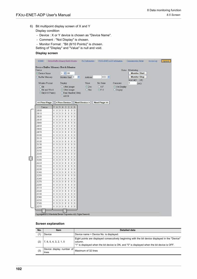
8 Data monitoring function
8.5 Screen
102
FX3U-ENET-ADP User's Manual
6) Bit multipoint display screen of X and Y
Display condition
- Device : X or Y device is chosen as "Device Name".
- Comment : "Not Display" is chosen.
- Monitor Format : "Bit (8/10 Points)" is chosen.Setting of "Display" and "Value" is null and void.
Display screen
Screen explanation
No. Item Detailed data
(1) Device Device name + Device No. is displayed.
(2) 7, 6, 5, 4, 3, 2, 1, 0
Eight points are displayed consecutively beginning with the bit device displayed in the "Device"
column.
"1" is displayed when the bit device is ON, and "0" is displayed when the bit device is OFF.
(3)Device display number of
linesMaximum of 32 lines
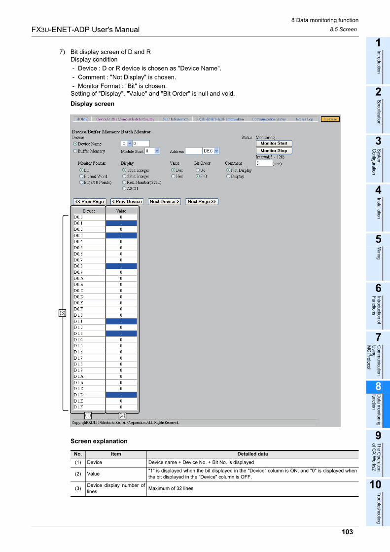
8 Data monitoring function
8.5 Screen
103
FX3U-ENET-ADP User's Manual
1
Introduction
2
Specification
3
System
C
onfiguration
4
Installation
5
Wiring
6
Introduction of F
unctions
7
Com
munication
Using
MC
Protocol
8
Data m
onitoring function
9
The O
peration of G
X W
orks2
10
Troubleshooting
7) Bit display screen of D and RDisplay condition
- Device : D or R device is chosen as "Device Name".
- Comment : "Not Display" is chosen.
- Monitor Format : "Bit" is chosen.Setting of "Display", "Value" and "Bit Order" is null and void.
Display screen
Screen explanation
No. Item Detailed data
(1) Device Device name + Device No. + Bit No. is displayed
(2) Value"1" is displayed when the bit displayed in the "Device" column is ON, and "0" is displayed when
the bit displayed in the "Device" column is OFF.
(3)Device display number of
linesMaximum of 32 lines
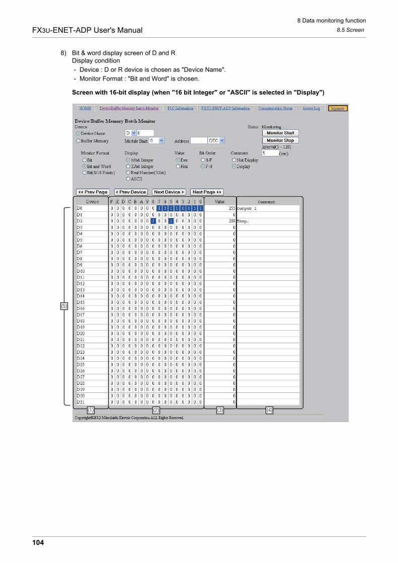
8 Data monitoring function
8.5 Screen
104
FX3U-ENET-ADP User's Manual
8) Bit & word display screen of D and RDisplay condition
- Device : D or R device is chosen as "Device Name".
- Monitor Format : "Bit and Word" is chosen.
Screen with 16-bit display (when "16 bit Integer" or "ASCII" is selected in "Display")
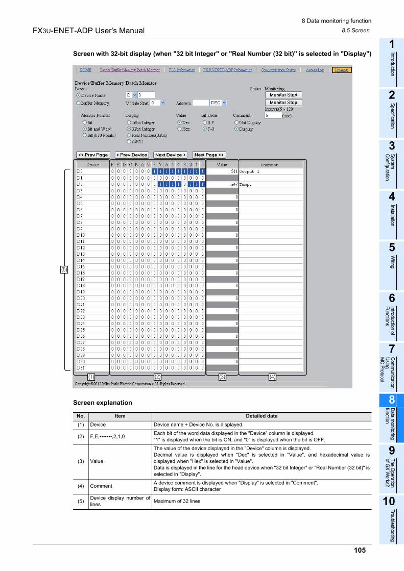
8 Data monitoring function
8.5 Screen
105
FX3U-ENET-ADP User's Manual
1
Introduction
2
Specification
3
System
C
onfiguration
4
Installation
5
Wiring
6
Introduction of F
unctions
7
Com
munication
Using
MC
Protocol
8
Data m
onitoring function
9
The O
peration of G
X W
orks2
10
Troubleshooting
Screen with 32-bit display (when "32 bit Integer" or "Real Number (32 bit)" is selected in "Display")
Screen explanation
No. Item Detailed data
(1) Device Device name + Device No. is displayed.
(2) F,E,�������,2,1,0Each bit of the word data displayed in the "Device" column is displayed.
"1" is displayed when the bit is ON, and "0" is displayed when the bit is OFF.
(3) Value
The value of the device displayed in the "Device" column is displayed.
Decimal value is displayed when "Dec" is selected in "Value", and hexadecimal value is
displayed when "Hex" is selected in "Value".
Data is displayed in the line for the head device when "32 bit Integer" or "Real Number (32 bit)" is
selected in "Display".
(4) CommentA device comment is displayed when "Display" is selected in "Comment".
Display form: ASCII character
(5)Device display number of
linesMaximum of 32 lines
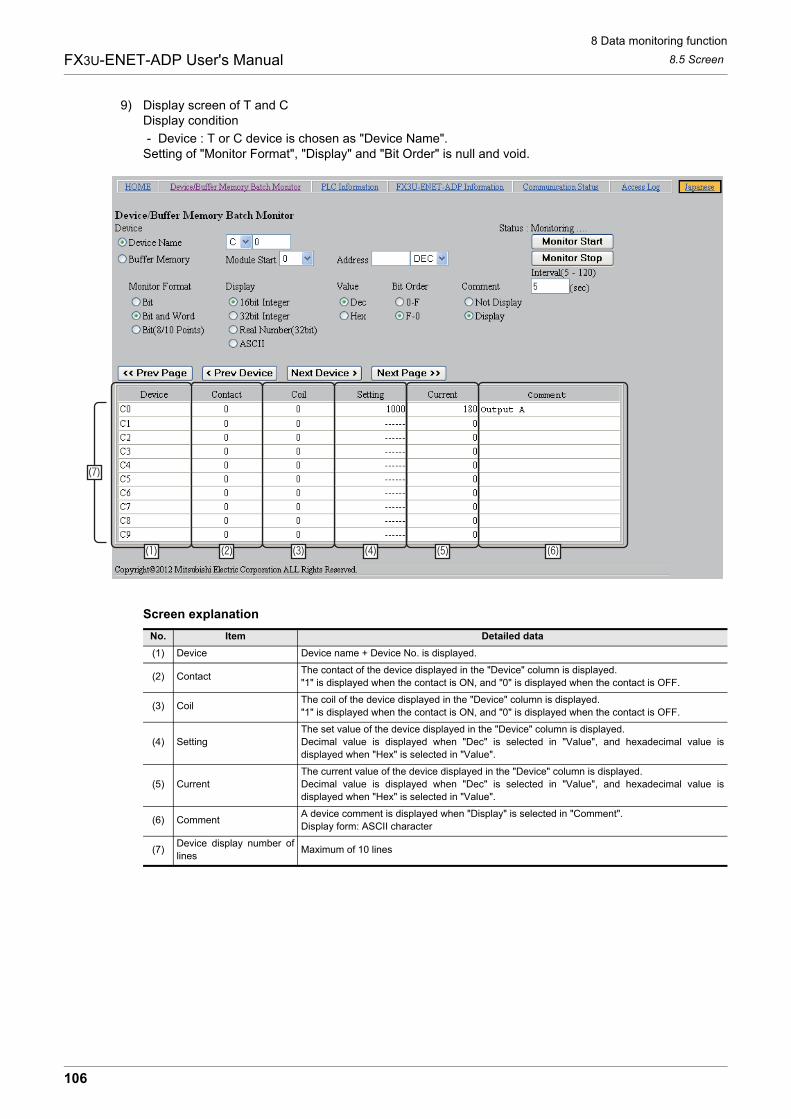
8 Data monitoring function
8.5 Screen
106
FX3U-ENET-ADP User's Manual
9) Display screen of T and CDisplay condition
- Device : T or C device is chosen as "Device Name".Setting of "Monitor Format", "Display" and "Bit Order" is null and void.
Screen explanation
No. Item Detailed data
(1) Device Device name + Device No. is displayed.
(2) ContactThe contact of the device displayed in the "Device" column is displayed.
"1" is displayed when the contact is ON, and "0" is displayed when the contact is OFF.
(3) CoilThe coil of the device displayed in the "Device" column is displayed.
"1" is displayed when the contact is ON, and "0" is displayed when the contact is OFF.
(4) Setting
The set value of the device displayed in the "Device" column is displayed.
Decimal value is displayed when "Dec" is selected in "Value", and hexadecimal value is
displayed when "Hex" is selected in "Value".
(5) Current
The current value of the device displayed in the "Device" column is displayed.
Decimal value is displayed when "Dec" is selected in "Value", and hexadecimal value is
displayed when "Hex" is selected in "Value".
(6) CommentA device comment is displayed when "Display" is selected in "Comment".
Display form: ASCII character
(7)Device display number of
linesMaximum of 10 lines
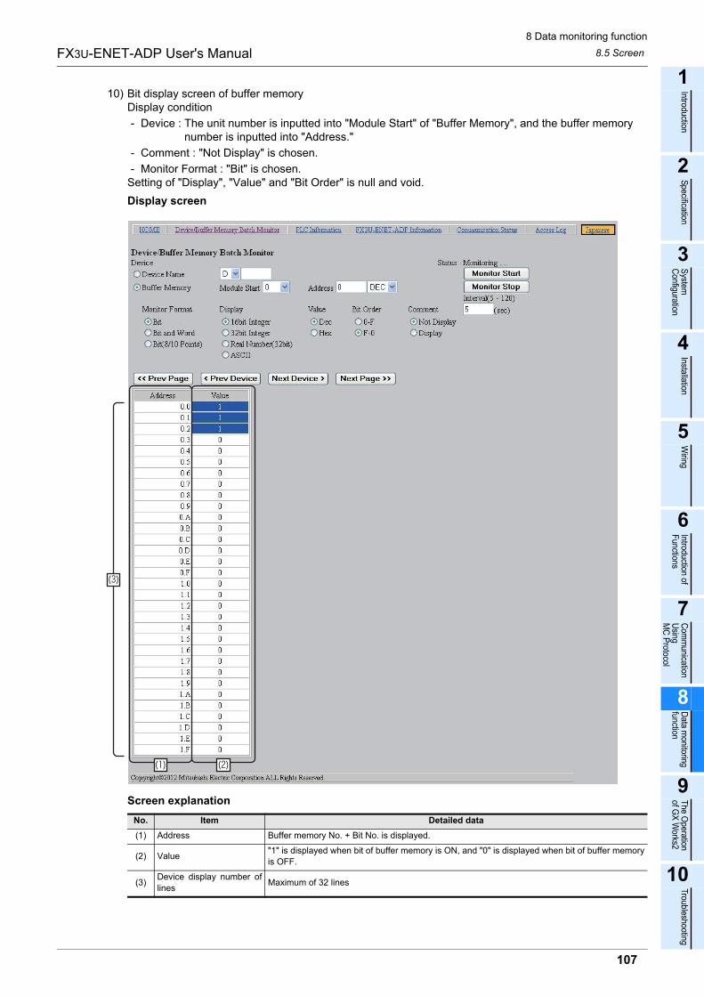
8 Data monitoring function
8.5 Screen
107
FX3U-ENET-ADP User's Manual
1
Introduction
2
Specification
3
System
C
onfiguration
4
Installation
5
Wiring
6
Introduction of F
unctions
7
Com
munication
Using
MC
Protocol
8
Data m
onitoring function
9
The O
peration of G
X W
orks2
10
Troubleshooting
10) Bit display screen of buffer memoryDisplay condition
- Device : The unit number is inputted into "Module Start" of "Buffer Memory", and the buffer memory number is inputted into "Address."
- Comment : "Not Display" is chosen.
- Monitor Format : "Bit" is chosen.Setting of "Display", "Value" and "Bit Order" is null and void.
Display screen
Screen explanation
No. Item Detailed data
(1) Address Buffer memory No. + Bit No. is displayed.
(2) Value"1" is displayed when bit of buffer memory is ON, and "0" is displayed when bit of buffer memory
is OFF.
(3)Device display number of
linesMaximum of 32 lines
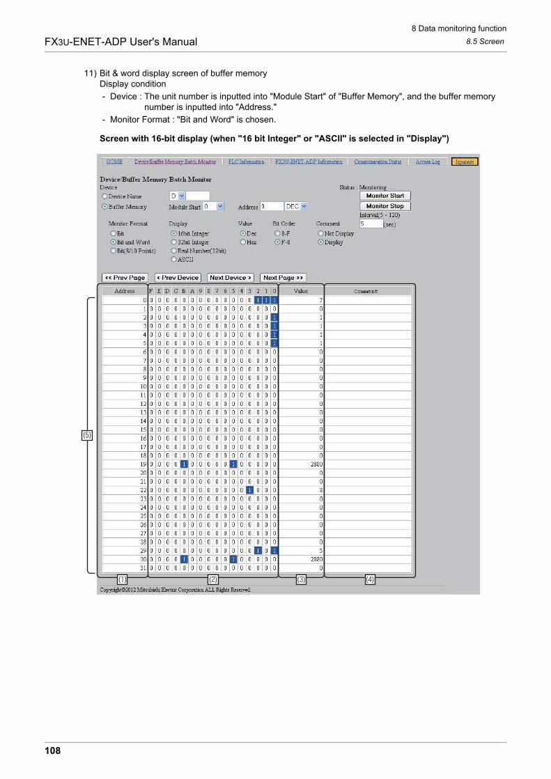
8 Data monitoring function
8.5 Screen
108
FX3U-ENET-ADP User's Manual
11) Bit & word display screen of buffer memoryDisplay condition
- Device : The unit number is inputted into "Module Start" of "Buffer Memory", and the buffer memory number is inputted into "Address."
- Monitor Format : "Bit and Word" is chosen.
Screen with 16-bit display (when "16 bit Integer" or "ASCII" is selected in "Display")
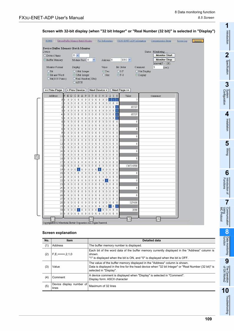
8 Data monitoring function
8.5 Screen
109
FX3U-ENET-ADP User's Manual
1
Introduction
2
Specification
3
System
C
onfiguration
4
Installation
5
Wiring
6
Introduction of F
unctions
7
Com
munication
Using
MC
Protocol
8
Data m
onitoring function
9
The O
peration of G
X W
orks2
10
Troubleshooting
Screen with 32-bit display (when "32 bit Integer" or "Real Number (32 bit)" is selected in "Display")
Screen explanation
No. Item Detailed data
(1) Address The buffer memory number is displayed.
(2) F,E,�������,2,1,0
Each bit of the word data of the buffer memory currently displayed in the "Address" column is
shown.
"1" is displayed when the bit is ON, and "0" is displayed when the bit is OFF.
(3) Value
The value of the buffer memory displayed in the "Address" column is shown.
Data is displayed in the line for the head device when "32 bit Integer" or "Real Number (32 bit)" is
selected in "Display".
(4) CommentA device comment is displayed when "Display" is selected in "Comment".
Display form: ASCII character
(5)Device display number of
linesMaximum of 32 lines
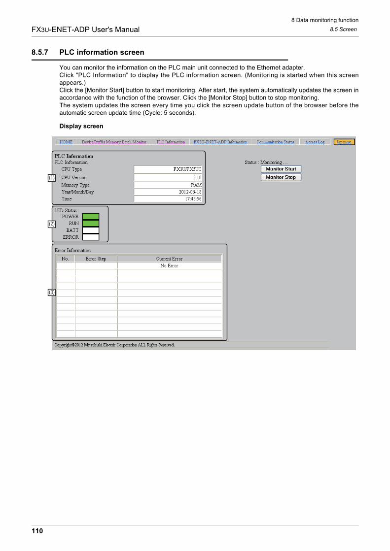
8 Data monitoring function
8.5 Screen
110
FX3U-ENET-ADP User's Manual
8.5.7 PLC information screen
You can monitor the information on the PLC main unit connected to the Ethernet adapter.Click "PLC Information" to display the PLC information screen. (Monitoring is started when this screenappears.)Click the [Monitor Start] button to start monitoring. After start, the system automatically updates the screen inaccordance with the function of the browser. Click the [Monitor Stop] button to stop monitoring.The system updates the screen every time you click the screen update button of the browser before theautomatic screen update time (Cycle: 5 seconds).
Display screen
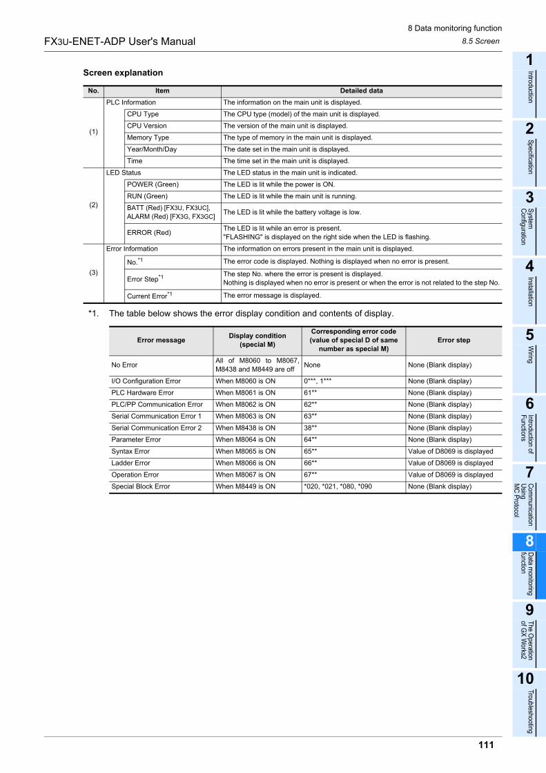
8 Data monitoring function
8.5 Screen
111
FX3U-ENET-ADP User's Manual
1
Introduction
2
Specification
3
System
C
onfiguration
4
Installation
5
Wiring
6
Introduction of F
unctions
7
Com
munication
Using
MC
Protocol
8
Data m
onitoring function
9
The O
peration of G
X W
orks2
10
Troubleshooting
Screen explanation
*1. The table below shows the error display condition and contents of display.
No. Item Detailed data
(1)
PLC Information The information on the main unit is displayed.
CPU Type The CPU type (model) of the main unit is displayed.
CPU Version The version of the main unit is displayed.
Memory Type The type of memory in the main unit is displayed.
Year/Month/Day The date set in the main unit is displayed.
Time The time set in the main unit is displayed.
(2)
LED Status The LED status in the main unit is indicated.
POWER (Green) The LED is lit while the power is ON.
RUN (Green) The LED is lit while the main unit is running.
BATT (Red) [FX3U, FX3UC],
ALARM (Red) [FX3G, FX3GC]The LED is lit while the battery voltage is low.
ERROR (Red)The LED is lit while an error is present.
"FLASHING" is displayed on the right side when the LED is flashing.
(3)
Error Information The information on errors present in the main unit is displayed.
No.*1 The error code is displayed. Nothing is displayed when no error is present.
Error Step*1 The step No. where the error is present is displayed.
Nothing is displayed when no error is present or when the error is not related to the step No.
Current Error*1 The error message is displayed.
Error messageDisplay condition
(special M)
Corresponding error code
(value of special D of same
number as special M)
Error step
No ErrorAll of M8060 to M8067,
M8438 and M8449 are offNone None (Blank display)
I/O Configuration Error When M8060 is ON 0***, 1*** None (Blank display)
PLC Hardware Error When M8061 is ON 61** None (Blank display)
PLC/PP Communication Error When M8062 is ON 62** None (Blank display)
Serial Communication Error 1 When M8063 is ON 63** None (Blank display)
Serial Communication Error 2 When M8438 is ON 38** None (Blank display)
Parameter Error When M8064 is ON 64** None (Blank display)
Syntax Error When M8065 is ON 65** Value of D8069 is displayed
Ladder Error When M8066 is ON 66** Value of D8069 is displayed
Operation Error When M8067 is ON 67** Value of D8069 is displayed
Special Block Error When M8449 is ON *020, *021, *080, *090 None (Blank display)
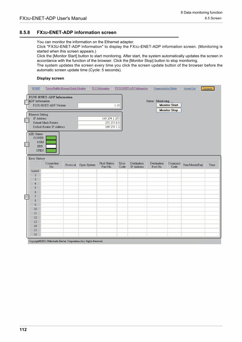
8 Data monitoring function
8.5 Screen
112
FX3U-ENET-ADP User's Manual
8.5.8 FX3U-ENET-ADP information screen
You can monitor the information on the Ethernet adapter.Click "FX3U-ENET-ADP Information" to display the FX3U-ENET-ADP information screen. (Monitoring isstarted when this screen appears.)Click the [Monitor Start] button to start monitoring. After start, the system automatically updates the screen inaccordance with the function of the browser. Click the [Monitor Stop] button to stop monitoring.The system updates the screen every time you click the screen update button of the browser before theautomatic screen update time (Cycle: 5 seconds).
Display screen
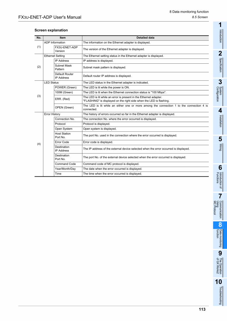
8 Data monitoring function
8.5 Screen
113
FX3U-ENET-ADP User's Manual
1
Introduction
2
Specification
3
System
C
onfiguration
4
Installation
5
Wiring
6
Introduction of F
unctions
7
Com
munication
Using
MC
Protocol
8
Data m
onitoring function
9
The O
peration of G
X W
orks2
10
Troubleshooting
Screen explanation
No. Item Detailed data
(1)
ADP Information The information on the Ethernet adapter is displayed.
FX3U-ENET-ADP
VersionThe version of the Ethernet adapter is displayed.
(2)
Ethernet Setting The Ethernet setting status in the Ethernet adapter is displayed.
IP Address IP address is displayed.
Subnet Mask
PatternSubnet mask pattern is displayed.
Default Router
IP AddressDefault router IP address is displayed.
(3)
LED Status The LED status in the Ethernet adapter is indicated.
POWER (Green) The LED is lit while the power is ON.
100M (Green) The LED is lit when the Ethernet connection status is "100 Mbps".
ERR. (Red)The LED is lit while an error is present in the Ethernet adapter.
"FLASHING" is displayed on the right side when the LED is flashing.
OPEN (Green)The LED is lit while an either one or more among the connection 1 to the connection 4 is
connected.
(4)
Error History The history of errors occurred so far in the Ethernet adapter is displayed.
Connection No. The connection No. where the error occurred is displayed.
Protocol Protocol is displayed.
Open System Open system is displayed.
Host Station
Port No.The port No. used in the connection where the error occurred is displayed.
Error Code Error code is displayed.
Destination
IP AddressThe IP address of the external device selected when the error occurred is displayed.
Destination
Port No.The port No. of the external device selected when the error occurred is displayed.
Command Code Command code of MC protocol is displayed.
Year/Month/Day The date when the error occurred is displayed.
Time The time when the error occurred is displayed.
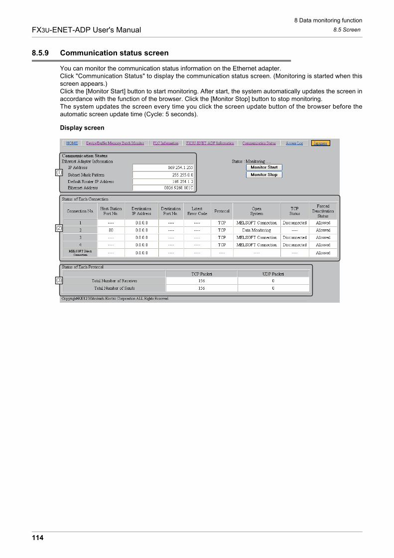
8 Data monitoring function
8.5 Screen
114
FX3U-ENET-ADP User's Manual
8.5.9 Communication status screen
You can monitor the communication status information on the Ethernet adapter.Click "Communication Status" to display the communication status screen. (Monitoring is started when thisscreen appears.)Click the [Monitor Start] button to start monitoring. After start, the system automatically updates the screen inaccordance with the function of the browser. Click the [Monitor Stop] button to stop monitoring.The system updates the screen every time you click the screen update button of the browser before theautomatic screen update time (Cycle: 5 seconds).
Display screen
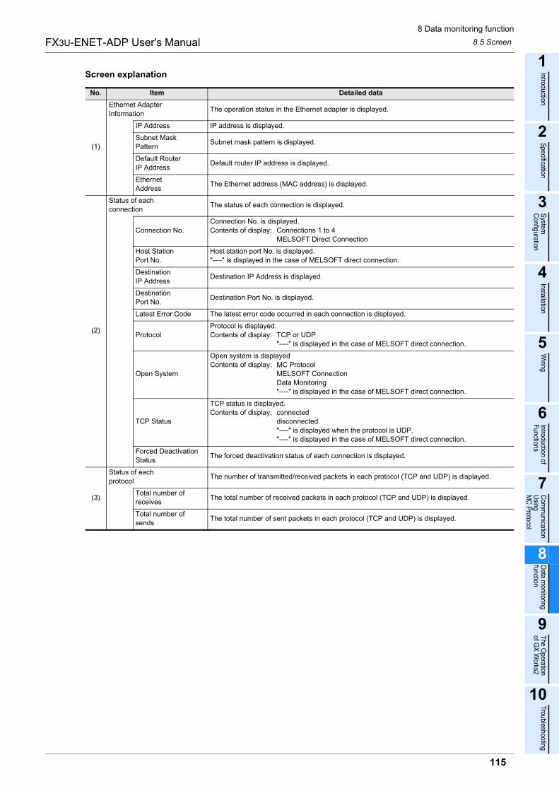
8 Data monitoring function
8.5 Screen
115
FX3U-ENET-ADP User's Manual
1
Introduction
2
Specification
3
System
C
onfiguration
4
Installation
5
Wiring
6
Introduction of F
unctions
7
Com
munication
Using
MC
Protocol
8
Data m
onitoring function
9
The O
peration of G
X W
orks2
10
Troubleshooting
Screen explanation
No. Item Detailed data
(1)
Ethernet Adapter
InformationThe operation status in the Ethernet adapter is displayed.
IP Address IP address is displayed.
Subnet Mask
PatternSubnet mask pattern is displayed.
Default Router
IP AddressDefault router IP address is displayed.
Ethernet
AddressThe Ethernet address (MAC address) is displayed.
(2)
Status of each
connectionThe status of each connection is displayed.
Connection No.
Connection No. is displayed.
Contents of display: Connections 1 to 4
MELSOFT Direct Connection
Host Station
Port No.
Host station port No. is displayed.
"----" is displayed in the case of MELSOFT direct connection.
Destination
IP AddressDestination IP Address is displayed.
Destination
Port No.Destination Port No. is displayed.
Latest Error Code The latest error code occurred in each connection is displayed.
Protocol
Protocol is displayed.
Contents of display: TCP or UDP
"----" is displayed in the case of MELSOFT direct connection.
Open System
Open system is displayed
Contents of display: MC Protocol
MELSOFT Connection
Data Monitoring
"----" is displayed in the case of MELSOFT direct connection.
TCP Status
TCP status is displayed.
Contents of display: connected
disconnected
"----" is displayed when the protocol is UDP.
"----" is displayed in the case of MELSOFT direct connection.
Forced Deactivation
StatusThe forced deactivation status of each connection is displayed.
(3)
Status of each
protocolThe number of transmitted/received packets in each protocol (TCP and UDP) is displayed.
Total number of
receivesThe total number of received packets in each protocol (TCP and UDP) is displayed.
Total number of
sendsThe total number of sent packets in each protocol (TCP and UDP) is displayed.
8 Data monitoring function
8.5 Screen
116
FX3U-ENET-ADP User's Manual
8.5.10 Access log screen
You can monitor the access log in the Ethernet adapter.Click "Access Log" to display the Access log screen. (Monitoring is started when this screen appears.)Up to 32 cases are displayed.When the number of accesses exceeds 32, the oldest case is deleted, and latest 32 cases are displayed.Accesses are displayed from most recent to oldest.Access is logged based on the access method (MELSOFT connection, for example) and external deviceinformation, not for each connection opening.
Caution
Even if connections are opened and closed repeatedly, the opening and closing history is not recorded.In MELSOFT connection, the date and time are logged as a new access when the TCP connection is established again after 10 seconds or more of no activity.In data monitoring, the date and time are logged as a new access when the TCP connection is established again after 150 seconds or more of no activity.In MC protocol (TCP), the date and time are logged as a new access every time the TCP connection is established.In MC protocol (UDP), the date and time are logged only when data receiving is executed for the first time after power ON of the Ethernet adaptor (PLC).
Update of the screenClick the [Monitor Start] button to start monitoring. After start, the system automatically updates the screen inaccordance with the function of the browser. Click the [Monitor Stop] button to stop monitoring.The system updates the screen every time you click the screen update button of the browser before theautomatic screen update time (Cycle: 5 seconds).
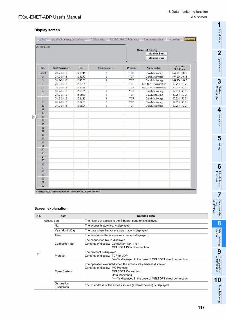
8 Data monitoring function
8.5 Screen
117
FX3U-ENET-ADP User's Manual
1
Introduction
2
Specification
3
System
C
onfiguration
4
Installation
5
Wiring
6
Introduction of F
unctions
7
Com
munication
Using
MC
Protocol
8
Data m
onitoring function
9
The O
peration of G
X W
orks2
10
Troubleshooting
Display screen
Screen explanation
No. Item Detailed data
(1)
Access Log The history of access to the Ethernet adapter is displayed.
No. The access history No. is displayed.
Year/Month/Day The date when the access was made is displayed.
Time The time when the access was made is displayed.
Connection No.
The connection No. is displayed.
Contents of display: Connection No. 1 to 4
MELSOFT Direct Connection
Protocol
The protocol is displayed.
Contents of display: TCP or UDP
"----" is displayed in the case of MELSOFT direct connection.
Open System
The operation executed when the access was made is displayed.
Contents of display: MC Protocol
MELSOFT Connection
Data Monitoring
"----" is displayed in the case of MELSOFT direct connection.
Destination
IP AddressThe IP address of the access source (external device) is displayed.
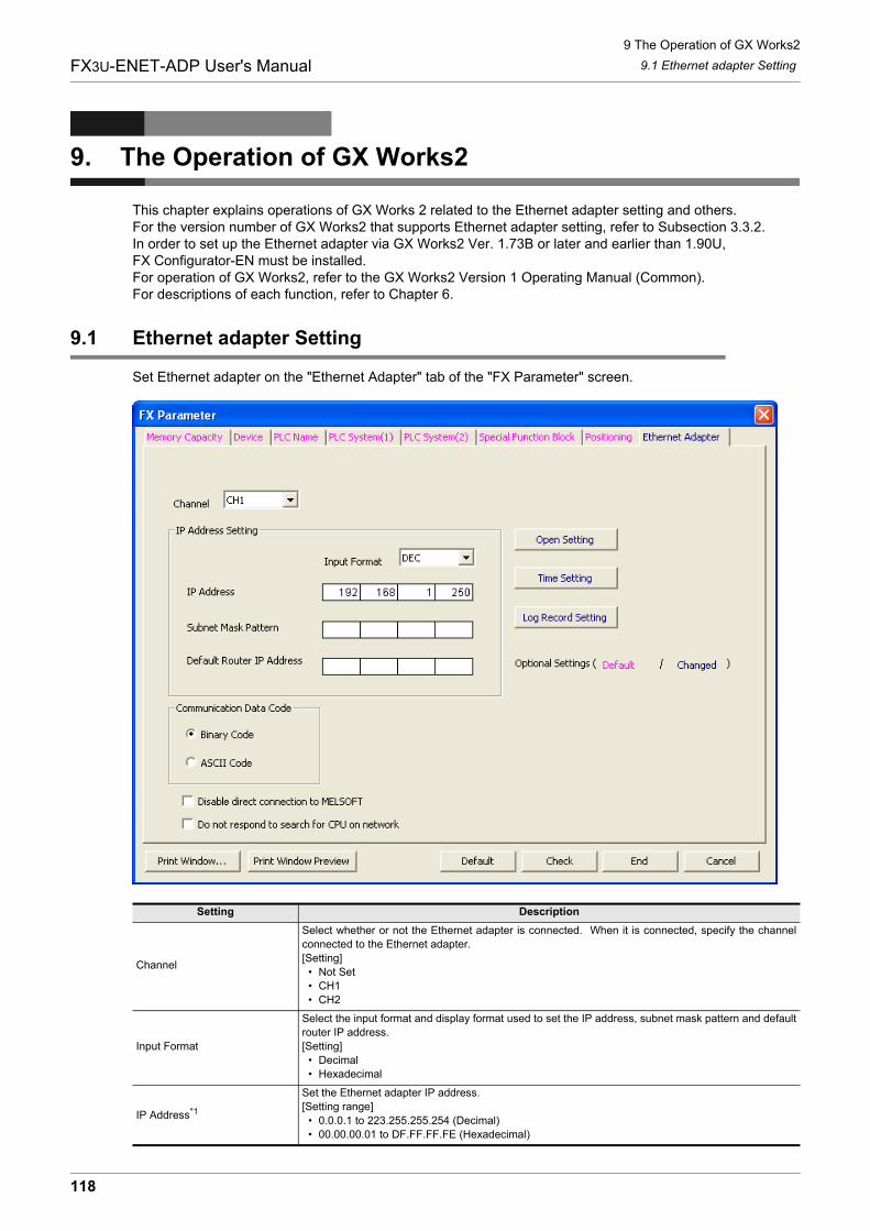
9 The Operation of GX Works2
9.1 Ethernet adapter Setting
118
FX3U-ENET-ADP User's Manual
9. The Operation of GX Works2
This chapter explains operations of GX Works 2 related to the Ethernet adapter setting and others.For the version number of GX Works2 that supports Ethernet adapter setting, refer to Subsection 3.3.2.In order to set up the Ethernet adapter via GX Works2 Ver. 1.73B or later and earlier than 1.90U, FX Configurator-EN must be installed.For operation of GX Works2, refer to the GX Works2 Version 1 Operating Manual (Common).For descriptions of each function, refer to Chapter 6.
9.1 Ethernet adapter Setting
Set Ethernet adapter on the "Ethernet Adapter" tab of the "FX Parameter" screen.
Setting Description
Channel
Select whether or not the Ethernet adapter is connected. When it is connected, specify the channel
connected to the Ethernet adapter.
[Setting]
� Not Set
� CH1
� CH2
Input Format
Select the input format and display format used to set the IP address, subnet mask pattern and default
router IP address.
[Setting]
� Decimal
� Hexadecimal
IP Address*1
Set the Ethernet adapter IP address.
[Setting range]
� 0.0.0.1 to 223.255.255.254 (Decimal)
� 00.00.00.01 to DF.FF.FF.FE (Hexadecimal)
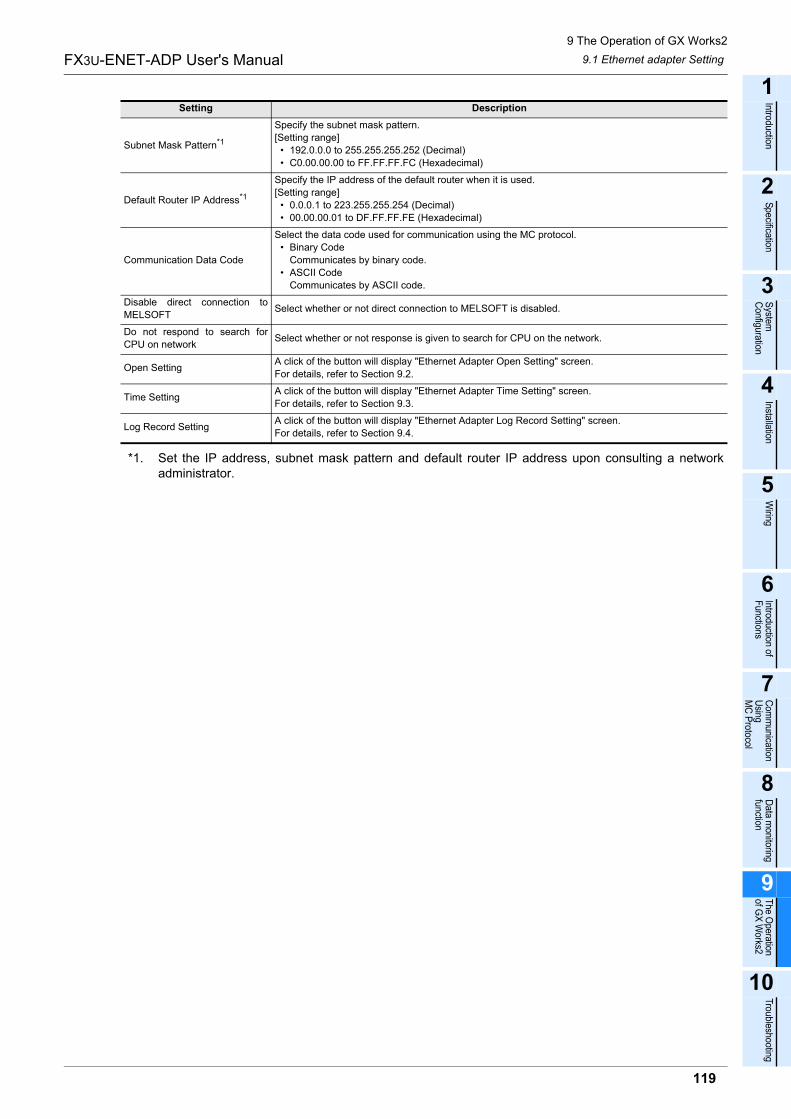
9 The Operation of GX Works2
9.1 Ethernet adapter Setting
119
FX3U-ENET-ADP User's Manual
1
Introduction
2
Specification
3
System
C
onfiguration
4
Installation
5
Wiring
6
Introduction of F
unctions
7
Com
munication
Using
MC
Protocol
8
Data m
onitoring function
9
The O
peration of G
X W
orks2
10
Troubleshooting
*1. Set the IP address, subnet mask pattern and default router IP address upon consulting a networkadministrator.
Subnet Mask Pattern*1
Specify the subnet mask pattern.
[Setting range]
� 192.0.0.0 to 255.255.255.252 (Decimal)
� C0.00.00.00 to FF.FF.FF.FC (Hexadecimal)
Default Router IP Address*1
Specify the IP address of the default router when it is used.
[Setting range]
� 0.0.0.1 to 223.255.255.254 (Decimal)
� 00.00.00.01 to DF.FF.FF.FE (Hexadecimal)
Communication Data Code
Select the data code used for communication using the MC protocol.
� Binary Code
Communicates by binary code.
� ASCII Code
Communicates by ASCII code.
Disable direct connection to
MELSOFTSelect whether or not direct connection to MELSOFT is disabled.
Do not respond to search for
CPU on networkSelect whether or not response is given to search for CPU on the network.
Open SettingA click of the button will display "Ethernet Adapter Open Setting" screen.
For details, refer to Section 9.2.
Time SettingA click of the button will display "Ethernet Adapter Time Setting" screen.
For details, refer to Section 9.3.
Log Record SettingA click of the button will display "Ethernet Adapter Log Record Setting" screen.
For details, refer to Section 9.4.
Setting Description
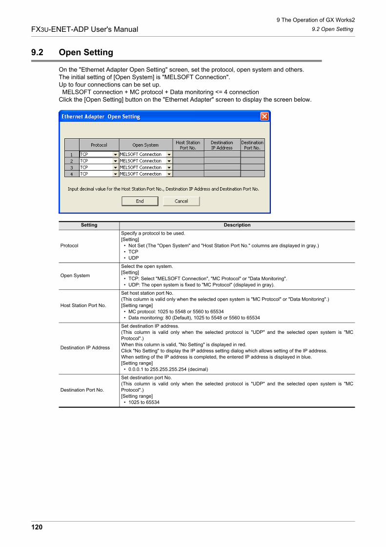
9 The Operation of GX Works2
9.2 Open Setting
120
FX3U-ENET-ADP User's Manual
9.2 Open Setting
On the "Ethernet Adapter Open Setting" screen, set the protocol, open system and others.The initial setting of [Open System] is "MELSOFT Connection".Up to four connections can be set up. MELSOFT connection + MC protocol + Data monitoring <= 4 connectionClick the [Open Setting] button on the "Ethernet Adapter" screen to display the screen below.
Setting Description
Protocol
Specify a protocol to be used.
[Setting]
� Not Set (The "Open System" and "Host Station Port No." columns are displayed in gray.)
� TCP
� UDP
Open System
Select the open system.
[Setting]
� TCP: Select "MELSOFT Connection", "MC Protocol" or "Data Monitoring".
� UDP: The open system is fixed to "MC Protocol" (displayed in gray).
Host Station Port No.
Set host station port No.
(This column is valid only when the selected open system is "MC Protocol" or "Data Monitoring".)
[Setting range]
� MC protocol: 1025 to 5548 or 5560 to 65534
� Data monitoring: 80 (Default), 1025 to 5548 or 5560 to 65534
Destination IP Address
Set destination IP address.
(This column is valid only when the selected protocol is "UDP" and the selected open system is "MC
Protocol".)
When this column is valid, "No Setting" is displayed in red.
Click "No Setting" to display the IP address setting dialog which allows setting of the IP address.
When setting of the IP address is completed, the entered IP address is displayed in blue.
[Setting range]
� 0.0.0.1 to 255.255.255.254 (decimal)
Destination Port No.
Set destination port No.
(This column is valid only when the selected protocol is "UDP" and the selected open system is "MC
Protocol".)
[Setting range]
� 1025 to 65534
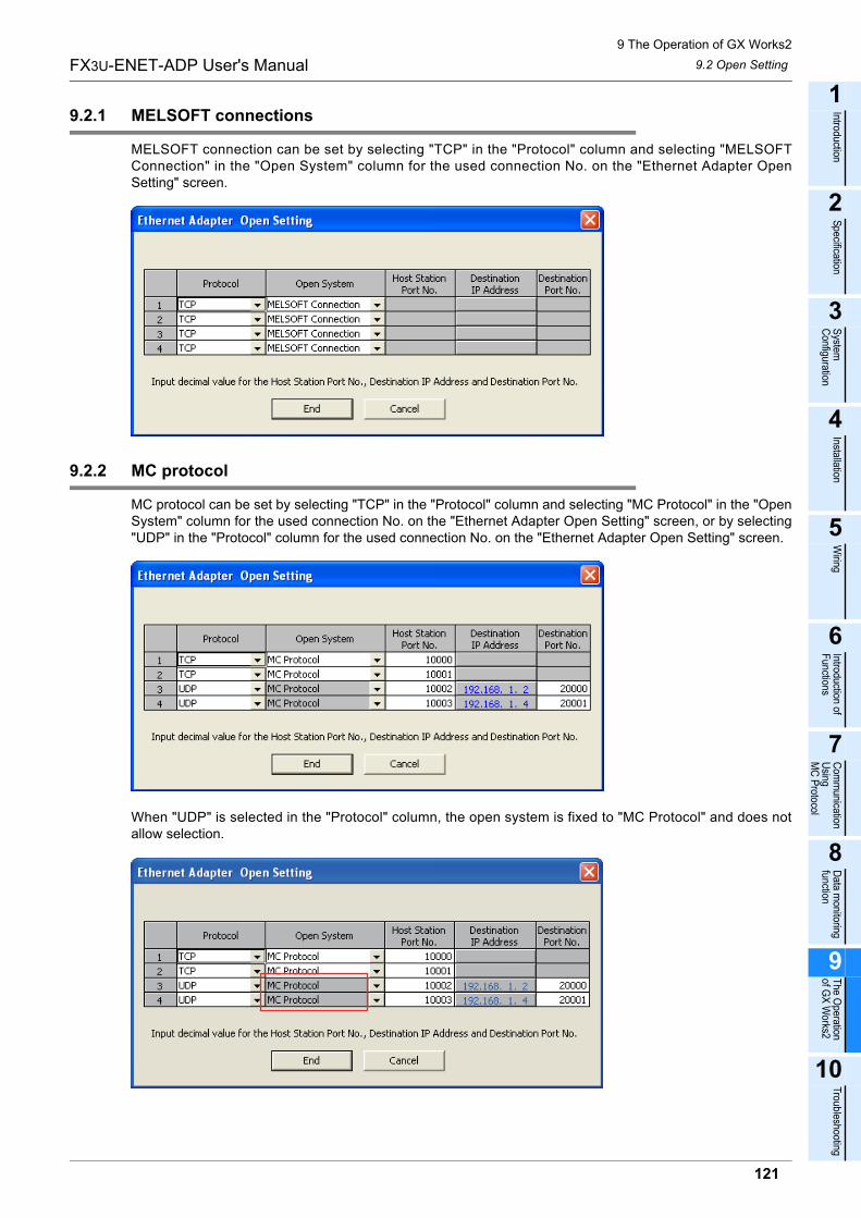
9 The Operation of GX Works2
9.2 Open Setting
121
FX3U-ENET-ADP User's Manual
1
Introduction
2
Specification
3
System
C
onfiguration
4
Installation
5
Wiring
6
Introduction of F
unctions
7
Com
munication
Using
MC
Protocol
8
Data m
onitoring function
9
The O
peration of G
X W
orks2
10
Troubleshooting
9.2.1 MELSOFT connections
MELSOFT connection can be set by selecting "TCP" in the "Protocol" column and selecting "MELSOFTConnection" in the "Open System" column for the used connection No. on the "Ethernet Adapter OpenSetting" screen.
9.2.2 MC protocol
MC protocol can be set by selecting "TCP" in the "Protocol" column and selecting "MC Protocol" in the "OpenSystem" column for the used connection No. on the "Ethernet Adapter Open Setting" screen, or by selecting"UDP" in the "Protocol" column for the used connection No. on the "Ethernet Adapter Open Setting" screen.
When "UDP" is selected in the "Protocol" column, the open system is fixed to "MC Protocol" and does notallow selection.
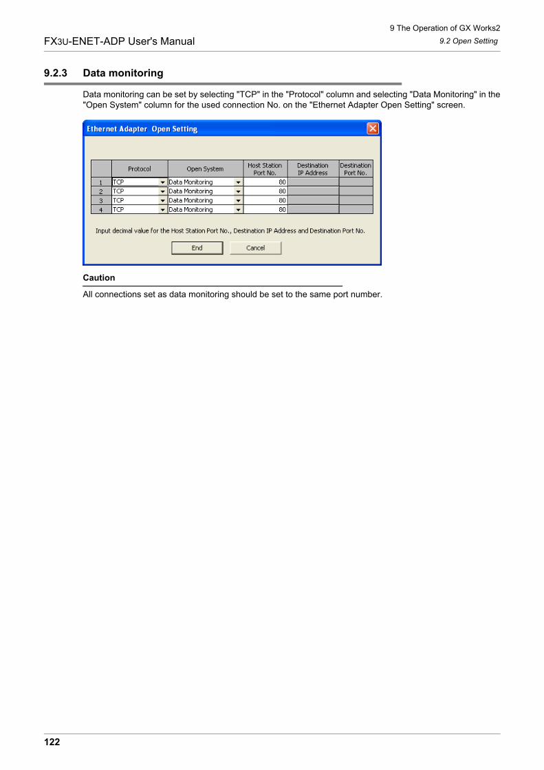
9 The Operation of GX Works2
9.2 Open Setting
122
FX3U-ENET-ADP User's Manual
9.2.3 Data monitoring
Data monitoring can be set by selecting "TCP" in the "Protocol" column and selecting "Data Monitoring" in the"Open System" column for the used connection No. on the "Ethernet Adapter Open Setting" screen.
Caution
All connections set as data monitoring should be set to the same port number.
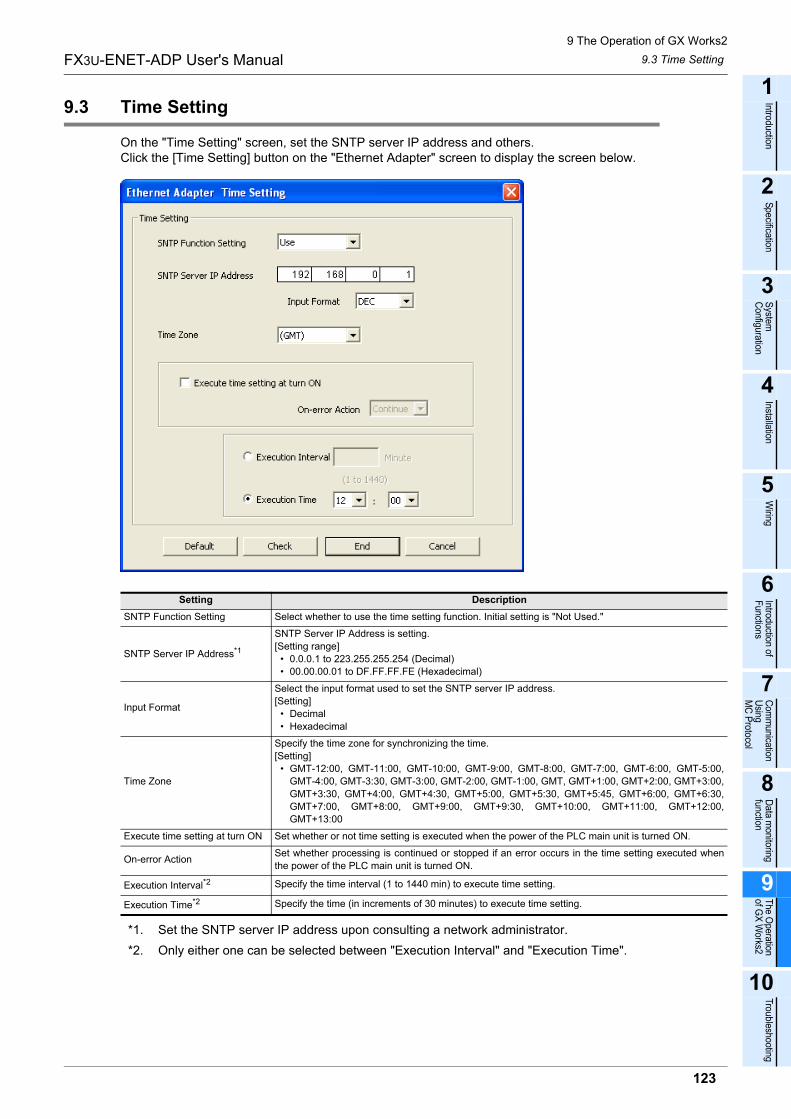
9 The Operation of GX Works2
9.3 Time Setting
123
FX3U-ENET-ADP User's Manual
1
Introduction
2
Specification
3
System
C
onfiguration
4
Installation
5
Wiring
6
Introduction of F
unctions
7
Com
munication
Using
MC
Protocol
8
Data m
onitoring function
9
The O
peration of G
X W
orks2
10
Troubleshooting
9.3 Time Setting
On the "Time Setting" screen, set the SNTP server IP address and others.Click the [Time Setting] button on the "Ethernet Adapter" screen to display the screen below.
*1. Set the SNTP server IP address upon consulting a network administrator.
*2. Only either one can be selected between "Execution Interval" and "Execution Time".
Setting Description
SNTP Function Setting Select whether to use the time setting function. Initial setting is "Not Used."
SNTP Server IP Address*1
SNTP Server IP Address is setting.
[Setting range]
� 0.0.0.1 to 223.255.255.254 (Decimal)
� 00.00.00.01 to DF.FF.FF.FE (Hexadecimal)
Input Format
Select the input format used to set the SNTP server IP address.
[Setting]
� Decimal
� Hexadecimal
Time Zone
Specify the time zone for synchronizing the time.
[Setting]
� GMT-12:00, GMT-11:00, GMT-10:00, GMT-9:00, GMT-8:00, GMT-7:00, GMT-6:00, GMT-5:00,
GMT-4:00, GMT-3:30, GMT-3:00, GMT-2:00, GMT-1:00, GMT, GMT+1:00, GMT+2:00, GMT+3:00,
GMT+3:30, GMT+4:00, GMT+4:30, GMT+5:00, GMT+5:30, GMT+5:45, GMT+6:00, GMT+6:30,
GMT+7:00, GMT+8:00, GMT+9:00, GMT+9:30, GMT+10:00, GMT+11:00, GMT+12:00,
GMT+13:00
Execute time setting at turn ON Set whether or not time setting is executed when the power of the PLC main unit is turned ON.
On-error ActionSet whether processing is continued or stopped if an error occurs in the time setting executed when
the power of the PLC main unit is turned ON.
Execution Interval*2 Specify the time interval (1 to 1440 min) to execute time setting.
Execution Time*2 Specify the time (in increments of 30 minutes) to execute time setting.
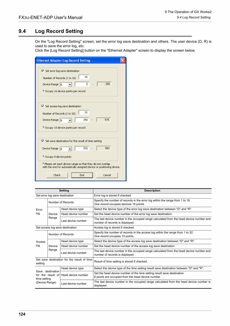
9 The Operation of GX Works2
9.4 Log Record Setting
124
FX3U-ENET-ADP User's Manual
9.4 Log Record Setting
On the "Log Record Setting" screen, set the error log save destination and others. The user device (D, R) isused to save the error log, etc.Click the [Log Record Setting] button on the "Ethernet Adapter" screen to display the screen below.
Setting Description
Set error log save destination Error log is stored if checked.
Error
log
Number of RecordsSpecify the number of records in the error log within the range from 1 to 16.
One record occupies devices 16 points.
Device
Range
Head device type Select the device type of the error log save destination between "D" and "R".
Head device number Set the head device number of the error log save destination.
Last device numberThe last device number in the occupied range calculated from the head device number and
number of records is displayed.
Set access log save destination Access log is stored if checked.
Access
log
Number of RecordsSpecify the number of records in the access log within the range from 1 to 32.
One record occupies 10 points.
Device
Range
Head device type Select the device type of the access log save destination between "D" and "R".
Head device number Set the head device number of the access log save destination.
Last device numberThe last device number in the occupied range calculated from the head device number and
number of records is displayed.
Set save destination for the result of time
settingResult of time setting is stored if checked.
Save destination
for the result of
time setting
(Device Range)
Head device type Select the device type of the time setting result save destination between "D" and "R".
Head device numberSet the head device number of the time setting result save destination.
8 points are occupied from the head device number.
Last device numberThe last device number in the occupied range calculated from the head device number is
displayed.
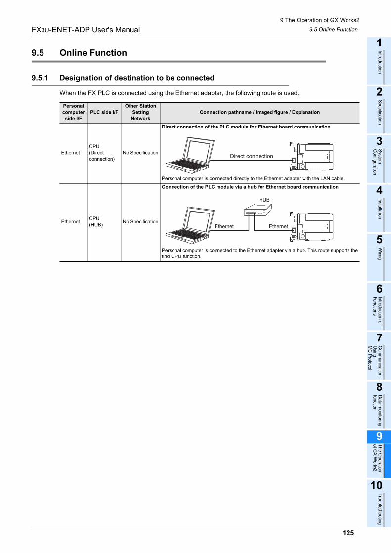
9 The Operation of GX Works2
9.5 Online Function
125
FX3U-ENET-ADP User's Manual
1
Introduction
2
Specification
3
System
C
onfiguration
4
Installation
5
Wiring
6
Introduction of F
unctions
7
Com
munication
Using
MC
Protocol
8
Data m
onitoring function
9
The O
peration of G
X W
orks2
10
Troubleshooting
9.5 Online Function
9.5.1 Designation of destination to be connected
When the FX PLC is connected using the Ethernet adapter, the following route is used.
Personal
computer
side I/F
PLC side I/F
Other Station
Setting
Network
Connection pathname / Imaged figure / Explanation
Ethernet
CPU
(Direct
connection)
No Specification
Direct connection of the PLC module for Ethernet board communication
Personal computer is connected directly to the Ethernet adapter with the LAN cable.
EthernetCPU
(HUB)No Specification
Connection of the PLC module via a hub for Ethernet board communication
Personal computer is connected to the Ethernet adapter via a hub. This route supports the
find CPU function.
Direct connection
Ethernet
HUB
Ethernet
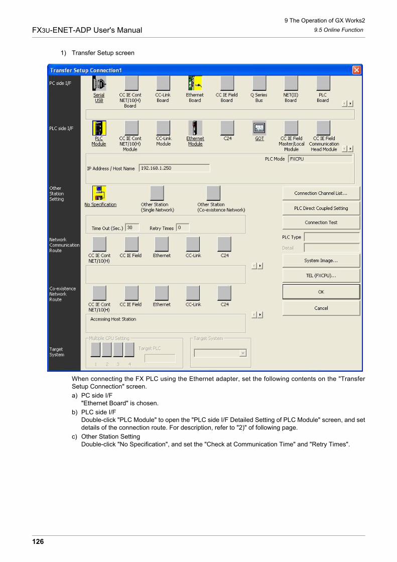
9 The Operation of GX Works2
9.5 Online Function
126
FX3U-ENET-ADP User's Manual
1) Transfer Setup screen
When connecting the FX PLC using the Ethernet adapter, set the following contents on the "TransferSetup Connection" screen.
a) PC side I/F"Ethernet Board" is chosen.
b) PLC side I/FDouble-click "PLC Module" to open the "PLC side I/F Detailed Setting of PLC Module" screen, and setdetails of the connection route. For description, refer to "2)" of following page.
c) Other Station SettingDouble-click "No Specification", and set the "Check at Communication Time" and "Retry Times".
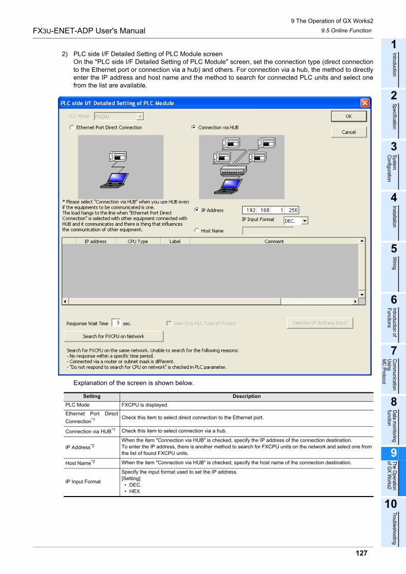
9 The Operation of GX Works2
9.5 Online Function
127
FX3U-ENET-ADP User's Manual
1
Introduction
2
Specification
3
System
C
onfiguration
4
Installation
5
Wiring
6
Introduction of F
unctions
7
Com
munication
Using
MC
Protocol
8
Data m
onitoring function
9
The O
peration of G
X W
orks2
10
Troubleshooting
2) PLC side I/F Detailed Setting of PLC Module screenOn the "PLC side I/F Detailed Setting of PLC Module" screen, set the connection type (direct connectionto the Ethernet port or connection via a hub) and others. For connection via a hub, the method to directlyenter the IP address and host name and the method to search for connected PLC units and select onefrom the list are available.
Explanation of the screen is shown below.
Setting Description
PLC Mode FXCPU is displayed.
Ethernet Port Direct
Connection*1 Check this item to select direct connection to the Ethernet port.
Connection via HUB*1 Check this item to select connection via a hub.
IP Address*2
When the item "Connection via HUB" is checked, specify the IP address of the connection destination.
To enter the IP address, there is another method to search for FXCPU units on the network and select one from
the list of found FXCPU units.
Host Name*2 When the item "Connection via HUB" is checked, specify the host name of the connection destination.
IP Input Format
Specify the input format used to set the IP address.
[Setting]
� DEC.
� HEX.
9 The Operation of GX Works2
9.5 Online Function
128
FX3U-ENET-ADP User's Manual
*1. Only one can be selected between "Ethernet Port Direct Connection" and "Connection via HUB".
*2. Only one can be selected between "IP Address" and "Host Name".
*3. When "*****" is displayed as the comment, the keyword setting in the main unit is set to "Read andwrite prohibited" or "All online operations prohibited".
9.5.2 Find CPU function
This function searches for CPU units connected to the Ethernet.In GX Works2 searches for CPU units connected to the same hub as GX Works2 from "PLC Side I/F DetailedSetting of PLC Module", and displays the list of found CPU units. Select a desired CPU unit from the list toobtain its IP address.
Connection CPU list
This list shows the result of searching for FX PLC main units connected on the network.
� IP address : Displays the IP address of a found PLC (in decimal).
� CPU type : Displays the CPU type of a found PLC. ("FX3G/FX3GC" or "FX3U/FX3UC" is displayed.)
� Label : Displays nothing because the FX PLC does not have any label.
� Comment : Displays the PLC parameter, PLC name setting and title in up to 32 half-width
characters.
It is possible to select (by double-clicking) a desired FX PLC from the list to enter the IP address.
Response Wait Time
Specify the response wait time in the find CPU function.
[Setting range]
� 0 to 99
Find CPU (FXCPU
Ethernet port) on
NetworkClick this button to execute search for FX PLC units connected on the network.*3
View Only PLC Type of
Project
Check this item so that only the CPU type selected in the project is displayed in the list of CPU units found on
the network.
Selection IP Address
InputClick this button to enter the IP address selected in the list of found CPU units to the "IP Address" input field.
Setting Description
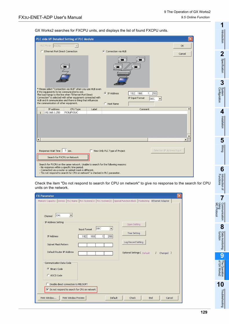
9 The Operation of GX Works2
9.5 Online Function
129
FX3U-ENET-ADP User's Manual
1
Introduction
2
Specification
3
System
C
onfiguration
4
Installation
5
Wiring
6
Introduction of F
unctions
7
Com
munication
Using
MC
Protocol
8
Data m
onitoring function
9
The O
peration of G
X W
orks2
10
Troubleshooting
GX Works2 searches for FXCPU units, and displays the list of found FXCPU units.
Check the item "Do not respond to search for CPU on network" to give no response to the search for CPUunits on the network.
9 The Operation of GX Works2
9.6 Ethernet Diagnostics
130
FX3U-ENET-ADP User's Manual
9.6 Ethernet Diagnostics
The Ethernet diagnostics function checks various setting status in the Ethernet adapter.
� Ethernet diagnostics function outlineWhen the Ethernet adapter is used, the Ethernet diagnostics function monitors and tests the following items.
For details, refer to Subsection 9.6.1 through Subsection 9.6.7.
Function Description
Parameter status IP address, Ethernet address, etc. are displayed.
Error history Connection No., Error code, Port number, Date, Time, etc. are displayed.
Status of each connection
(Access History)
� Status of each connection : Host station port No., Destination IP address, Destination port No., Latest
error code, etc. are displayed.
� Access History : Date, Time, Connection No., Destination IP address, etc. are displayed.
("Access History" is displayed together with "Status of each connection")
Status of each protocol TCP packet number and UDP packet number are displayed.
Connection status Full Duplex/Half Duplex, Connection status and 10BASE-T/100BASE-TX are displayed.
Time setting status Latest time setting, Time required for response are displayed.
PING testThis test checks the presence of Ethernet modules on the Ethernet network whose initial processing is
completed, or the presence of specified IP address.
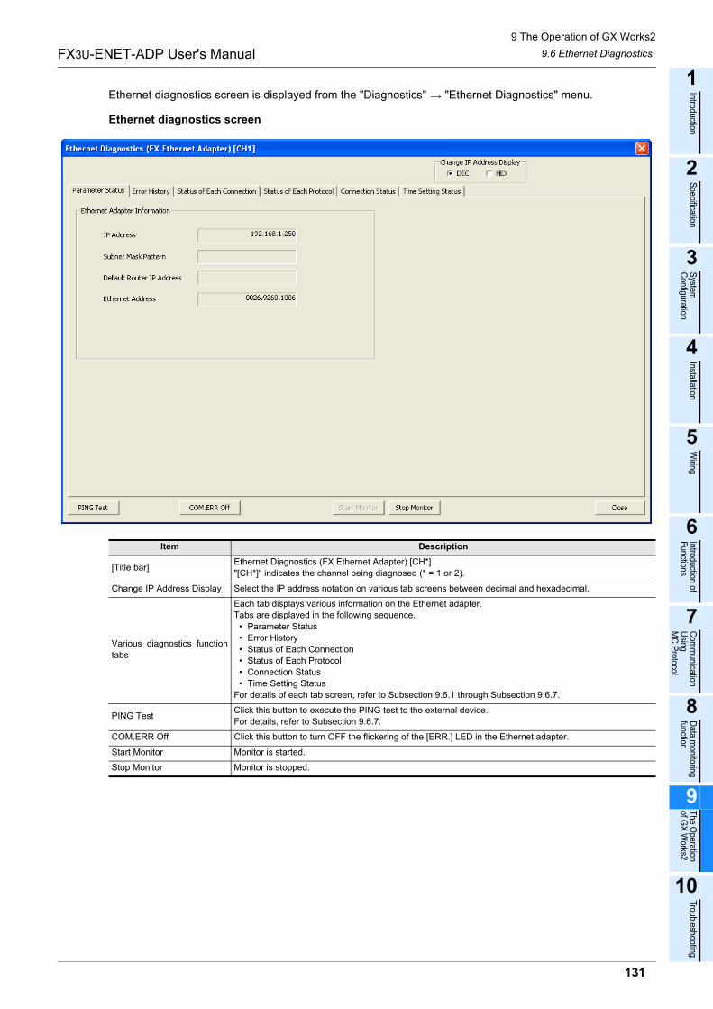
9 The Operation of GX Works2
9.6 Ethernet Diagnostics
131
FX3U-ENET-ADP User's Manual
1
Introduction
2
Specification
3
System
C
onfiguration
4
Installation
5
Wiring
6
Introduction of F
unctions
7
Com
munication
Using
MC
Protocol
8
Data m
onitoring function
9
The O
peration of G
X W
orks2
10
Troubleshooting
Ethernet diagnostics screen is displayed from the "Diagnostics" "Ethernet Diagnostics" menu.
Ethernet diagnostics screen
Item Description
[Title bar]Ethernet Diagnostics (FX Ethernet Adapter) [CH*]
"[CH*]" indicates the channel being diagnosed (* = 1 or 2).
Change IP Address Display Select the IP address notation on various tab screens between decimal and hexadecimal.
Various diagnostics function
tabs
Each tab displays various information on the Ethernet adapter.
Tabs are displayed in the following sequence.
� Parameter Status
� Error History
� Status of Each Connection
� Status of Each Protocol
� Connection Status
� Time Setting Status
For details of each tab screen, refer to Subsection 9.6.1 through Subsection 9.6.7.
PING TestClick this button to execute the PING test to the external device.
For details, refer to Subsection 9.6.7.
COM.ERR Off Click this button to turn OFF the flickering of the [ERR.] LED in the Ethernet adapter.
Start Monitor Monitor is started.
Stop Monitor Monitor is stopped.
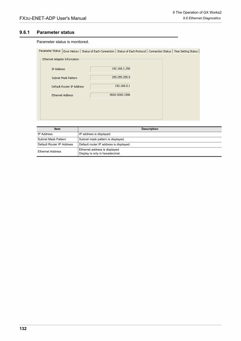
9 The Operation of GX Works2
9.6 Ethernet Diagnostics
132
FX3U-ENET-ADP User's Manual
9.6.1 Parameter status
Parameter status is monitored.
Item Description
IP Address IP address is displayed.
Subnet Mask Pattern Subnet mask pattern is displayed.
Default Router IP Address Default router IP address is displayed.
Ethernet AddressEthernet address is displayed.
Display is only in hexadecimal.
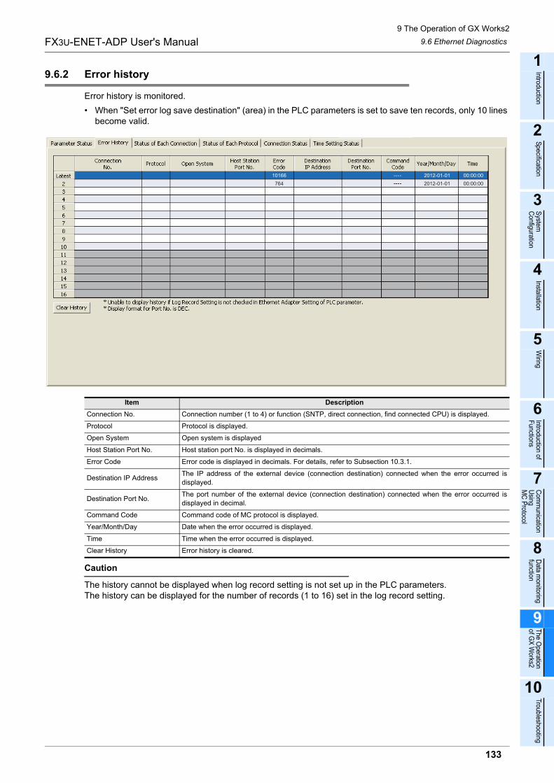
9 The Operation of GX Works2
9.6 Ethernet Diagnostics
133
FX3U-ENET-ADP User's Manual
1
Introduction
2
Specification
3
System
C
onfiguration
4
Installation
5
Wiring
6
Introduction of F
unctions
7
Com
munication
Using
MC
Protocol
8
Data m
onitoring function
9
The O
peration of G
X W
orks2
10
Troubleshooting
9.6.2 Error history
Error history is monitored.
� When "Set error log save destination" (area) in the PLC parameters is set to save ten records, only 10 lines become valid.
Caution
The history cannot be displayed when log record setting is not set up in the PLC parameters.The history can be displayed for the number of records (1 to 16) set in the log record setting.
Item Description
Connection No. Connection number (1 to 4) or function (SNTP, direct connection, find connected CPU) is displayed.
Protocol Protocol is displayed.
Open System Open system is displayed
Host Station Port No. Host station port No. is displayed in decimals.
Error Code Error code is displayed in decimals. For details, refer to Subsection 10.3.1.
Destination IP AddressThe IP address of the external device (connection destination) connected when the error occurred is
displayed.
Destination Port No.The port number of the external device (connection destination) connected when the error occurred is
displayed in decimal.
Command Code Command code of MC protocol is displayed.
Year/Month/Day Date when the error occurred is displayed.
Time Time when the error occurred is displayed.
Clear History Error history is cleared.
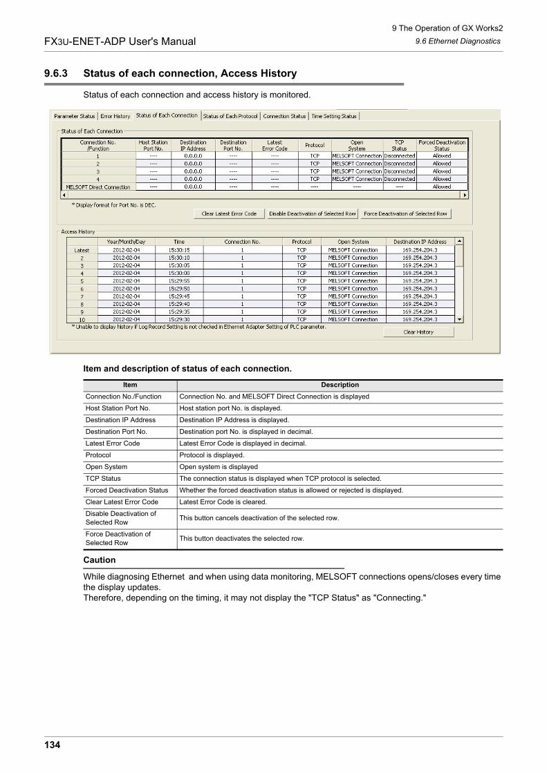
9 The Operation of GX Works2
9.6 Ethernet Diagnostics
134
FX3U-ENET-ADP User's Manual
9.6.3 Status of each connection, Access History
Status of each connection and access history is monitored.
Item and description of status of each connection.
Caution
While diagnosing Ethernet and when using data monitoring, MELSOFT connections opens/closes every time the display updates.Therefore, depending on the timing, it may not display the "TCP Status" as "Connecting."
Item Description
Connection No./Function Connection No. and MELSOFT Direct Connection is displayed
Host Station Port No. Host station port No. is displayed.
Destination IP Address Destination IP Address is displayed.
Destination Port No. Destination port No. is displayed in decimal.
Latest Error Code Latest Error Code is displayed in decimal.
Protocol Protocol is displayed.
Open System Open system is displayed
TCP Status The connection status is displayed when TCP protocol is selected.
Forced Deactivation Status Whether the forced deactivation status is allowed or rejected is displayed.
Clear Latest Error Code Latest Error Code is cleared.
Disable Deactivation of
Selected RowThis button cancels deactivation of the selected row.
Force Deactivation of
Selected RowThis button deactivates the selected row.
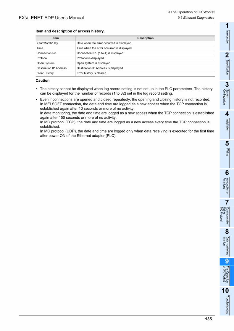
9 The Operation of GX Works2
9.6 Ethernet Diagnostics
135
FX3U-ENET-ADP User's Manual
1
Introduction
2
Specification
3
System
C
onfiguration
4
Installation
5
Wiring
6
Introduction of F
unctions
7
Com
munication
Using
MC
Protocol
8
Data m
onitoring function
9
The O
peration of G
X W
orks2
10
Troubleshooting
Item and description of access history.
Caution
� The history cannot be displayed when log record setting is not set up in the PLC parameters. The history can be displayed for the number of records (1 to 32) set in the log record setting.
� Even if connections are opened and closed repeatedly, the opening and closing history is not recorded.In MELSOFT connection, the date and time are logged as a new access when the TCP connection is established again after 10 seconds or more of no activity.In data monitoring, the date and time are logged as a new access when the TCP connection is established again after 150 seconds or more of no activity.In MC protocol (TCP), the date and time are logged as a new access every time the TCP connection is established.In MC protocol (UDP), the date and time are logged only when data receiving is executed for the first time after power ON of the Ethernet adaptor (PLC).
Item Description
Year/Month/Day Date when the error occurred is displayed.
Time Time when the error occurred is displayed.
Connection No. Connection No. (1 to 4) is displayed.
Protocol Protocol is displayed.
Open System Open system is displayed
Destination IP Address Destination IP Address is displayed
Clear History Error history is cleared.
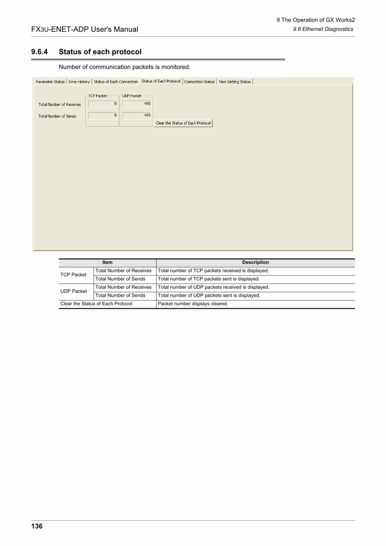
9 The Operation of GX Works2
9.6 Ethernet Diagnostics
136
FX3U-ENET-ADP User's Manual
9.6.4 Status of each protocol
Number of communication packets is monitored.
Item Description
TCP PacketTotal Number of Receives Total number of TCP packets received is displayed.
Total Number of Sends Total number of TCP packets sent is displayed.
UDP PacketTotal Number of Receives Total number of UDP packets received is displayed.
Total Number of Sends Total number of UDP packets sent is displayed.
Clear the Status of Each Protocol Packet number displays cleared.
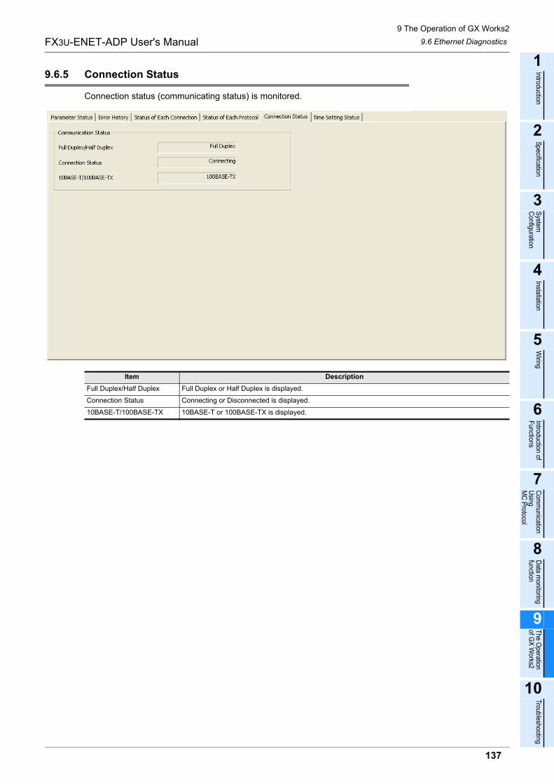
9 The Operation of GX Works2
9.6 Ethernet Diagnostics
137
FX3U-ENET-ADP User's Manual
1
Introduction
2
Specification
3
System
C
onfiguration
4
Installation
5
Wiring
6
Introduction of F
unctions
7
Com
munication
Using
MC
Protocol
8
Data m
onitoring function
9
The O
peration of G
X W
orks2
10
Troubleshooting
9.6.5 Connection Status
Connection status (communicating status) is monitored.
Item Description
Full Duplex/Half Duplex Full Duplex or Half Duplex is displayed.
Connection Status Connecting or Disconnected is displayed.
10BASE-T/100BASE-TX 10BASE-T or 100BASE-TX is displayed.
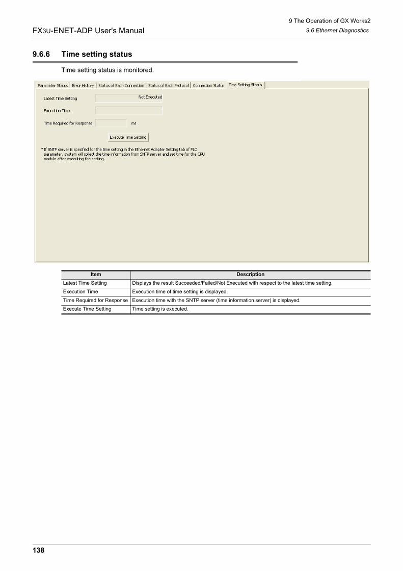
9 The Operation of GX Works2
9.6 Ethernet Diagnostics
138
FX3U-ENET-ADP User's Manual
9.6.6 Time setting status
Time setting status is monitored.
Item Description
Latest Time Setting Displays the result Succeeded/Failed/Not Executed with respect to the latest time setting.
Execution Time Execution time of time setting is displayed.
Time Required for Response Execution time with the SNTP server (time information server) is displayed.
Execute Time Setting Time setting is executed.
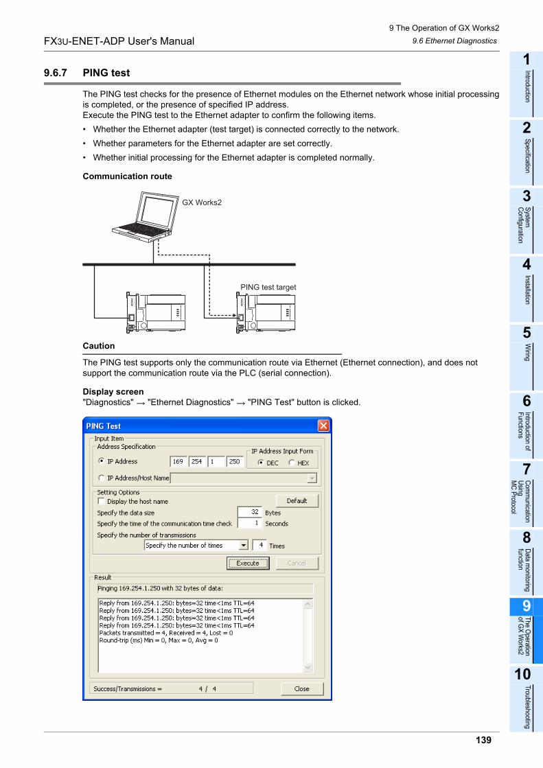
9 The Operation of GX Works2
9.6 Ethernet Diagnostics
139
FX3U-ENET-ADP User's Manual
1
Introduction
2
Specification
3
System
C
onfiguration
4
Installation
5
Wiring
6
Introduction of F
unctions
7
Com
munication
Using
MC
Protocol
8
Data m
onitoring function
9
The O
peration of G
X W
orks2
10
Troubleshooting
9.6.7 PING test
The PING test checks for the presence of Ethernet modules on the Ethernet network whose initial processingis completed, or the presence of specified IP address.Execute the PING test to the Ethernet adapter to confirm the following items.
� Whether the Ethernet adapter (test target) is connected correctly to the network.
� Whether parameters for the Ethernet adapter are set correctly.
� Whether initial processing for the Ethernet adapter is completed normally.
Communication route
Caution
The PING test supports only the communication route via Ethernet (Ethernet connection), and does not support the communication route via the PLC (serial connection).
Display screen"Diagnostics" "Ethernet Diagnostics" "PING Test" button is clicked.
GX Works2
PING test target
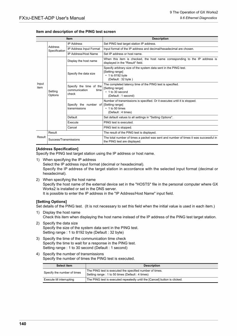
9 The Operation of GX Works2
9.6 Ethernet Diagnostics
140
FX3U-ENET-ADP User's Manual
Item and description of the PING test screen
[Address Specification]Specify the PING test target station using the IP address or host name.
1) When specifying the IP addressSelect the IP address input format (decimal or hexadecimal).Specify the IP address of the target station in accordance with the selected input format (decimal orhexadecimal).
2) When specifying the host nameSpecify the host name of the external device set in the "HOSTS" file in the personal computer where GXWorks2 is installed or set in the DNS server.It is possible to enter the IP address in the "IP Address/Host Name" input field.
[Setting Options]Set details of the PING test. (It is not necessary to set this field when the initial value is used in each item.)
1) Display the host nameCheck this item when displaying the host name instead of the IP address of the PING test target station.
2) Specify the data sizeSpecify the size of the system data sent in the PING test.Setting range : 1 to 8192 byte (Default : 32 byte)
3) Specify the time of the communication time checkSpecify the time to wait for a response in the PING test.Setting range : 1 to 30 second (Default : 1 second)
4) Specify the number of transmissionsSpecify the number of times the PING test is executed.
Item Description
Input
item
Address
Specification
IP Address Set PING test target station IP address.
IP Address Input Format Input format of the IP address and decimal/hexadecimal are chosen.
IP Address/Host Name Set IP address or host name.
Setting
Options
Display the host nameWhen this item is checked, the host name corresponding to the IP address is
displayed in the "Result" field.
Specify the data size
Specify arbitrary size of the system data sent in the PING test.
[Setting range]
� 1 to 8192 byte
(Default : 32 byte )
Specify the time of the
communication time
check
The completed latency time of the PING test is specified.
[Setting range]
� 1 to 30 second
(Default : 1 second)
Specify the number of
transmissions
Number of transmissions is specified. Or it executes until it is stopped.
[Setting range]
� 1 to 50 times
(Default : 4 times)
Default Set default values to all settings in "Setting Options".
Execute PING test is executed.
Cancel PING test is stopped.
Result
Result The result of the PING test is displayed.
Success/TransmissionsThe total number of times a packet was sent and number of times it was successful in
the PING test are displayed.
Select item Description
Specify the number of timesThe PING test is executed the specified number of times.
Setting range : 1 to 50 times (Default : 4 times)
Execute till interrupting The PING test is executed repeatedly until the [Cancel] button is clicked.
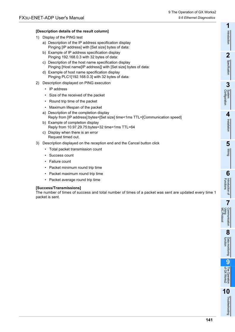
9 The Operation of GX Works2
9.6 Ethernet Diagnostics
141
FX3U-ENET-ADP User's Manual
1
Introduction
2
Specification
3
System
C
onfiguration
4
Installation
5
Wiring
6
Introduction of F
unctions
7
Com
munication
Using
MC
Protocol
8
Data m
onitoring function
9
The O
peration of G
X W
orks2
10
Troubleshooting
[Description details of the result column]
1) Display of the PING test
a) Description of the IP address specification displayPinging [IP address] with [Set size] bytes of data:
b) Example of IP address specification displayPinging 192.168.0.3 with 32 bytes of data:
c) Description of the host name specification displayPinging [Host name[IP address]] with [Set size] bytes of data:
d) Example of host name specification displayPinging PLC1[192.168.0.3] with 32 bytes of data:
2) Description displayed on PING execution
� IP address
� Size of the received of the packet
� Round trip time of the packet
� Maximum lifespan of the packet
a) Description of the completion displayReply from [IP address]:bytes=[Set size] time<1ms TTL=[Communication speed]
b) Example of completion displayReply from 10.97.29.75:bytes=32 time<1ms TTL=64
c) Display when there is an errorRequest timed out.
3) Description displayed on the reception end and the Cancel button click
� Total packet transmission count
� Success count
� Failure count
� Packet minimum round trip time
� Packet maximum round trip time
� Packet average round trip time
[Success/Transmissions]The number of times of success and total number of times of a packet was sent are updated every time 1packet is sent.
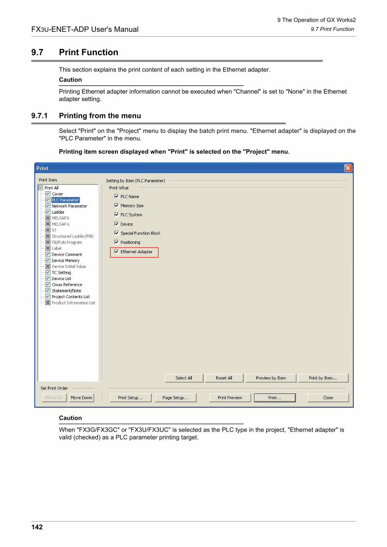
9 The Operation of GX Works2
9.7 Print Function
142
FX3U-ENET-ADP User's Manual
9.7 Print Function
This section explains the print content of each setting in the Ethernet adapter.
Caution
Printing Ethernet adapter information cannot be executed when "Channel" is set to "None" in the Ethernet adapter setting.
9.7.1 Printing from the menu
Select "Print" on the "Project" menu to display the batch print menu. "Ethernet adapter" is displayed on the"PLC Parameter" in the menu.
Printing item screen displayed when "Print" is selected on the "Project" menu.
Caution
When "FX3G/FX3GC" or "FX3U/FX3UC" is selected as the PLC type in the project, "Ethernet adapter" is valid (checked) as a PLC parameter printing target.
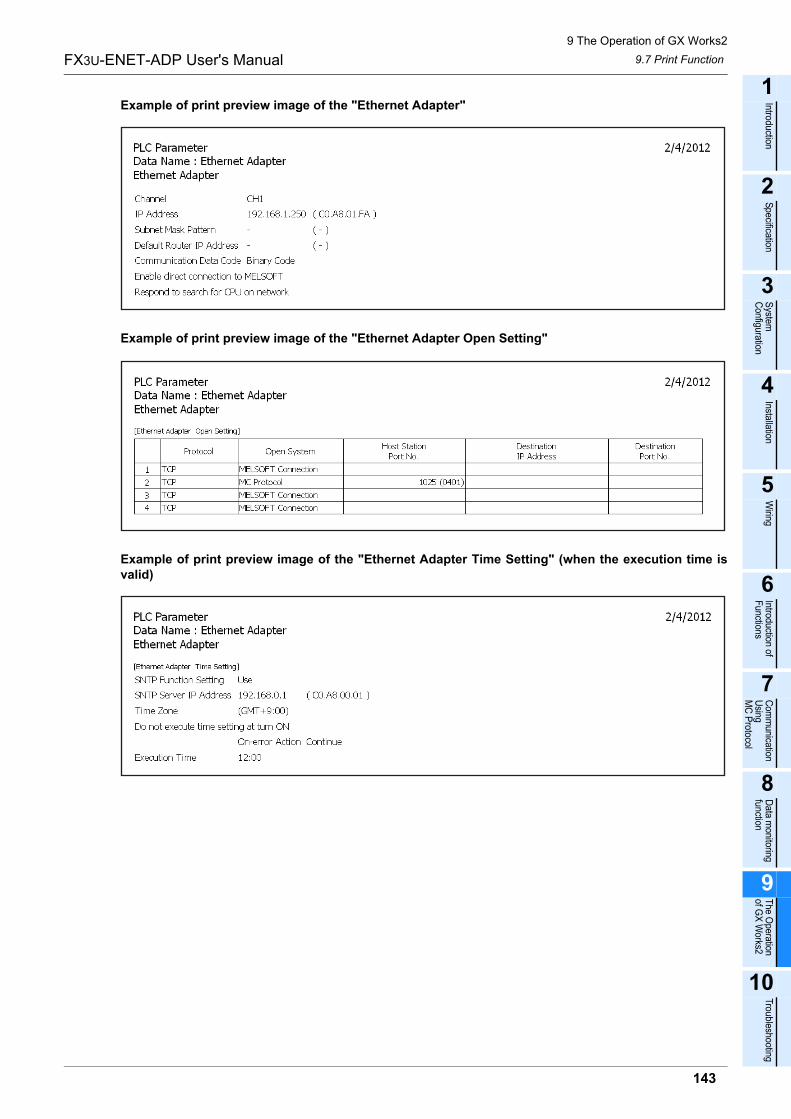
9 The Operation of GX Works2
9.7 Print Function
143
FX3U-ENET-ADP User's Manual
1
Introduction
2
Specification
3
System
C
onfiguration
4
Installation
5
Wiring
6
Introduction of F
unctions
7
Com
munication
Using
MC
Protocol
8
Data m
onitoring function
9
The O
peration of G
X W
orks2
10
Troubleshooting
Example of print preview image of the "Ethernet Adapter"
Example of print preview image of the "Ethernet Adapter Open Setting"
Example of print preview image of the "Ethernet Adapter Time Setting" (when the execution time isvalid)
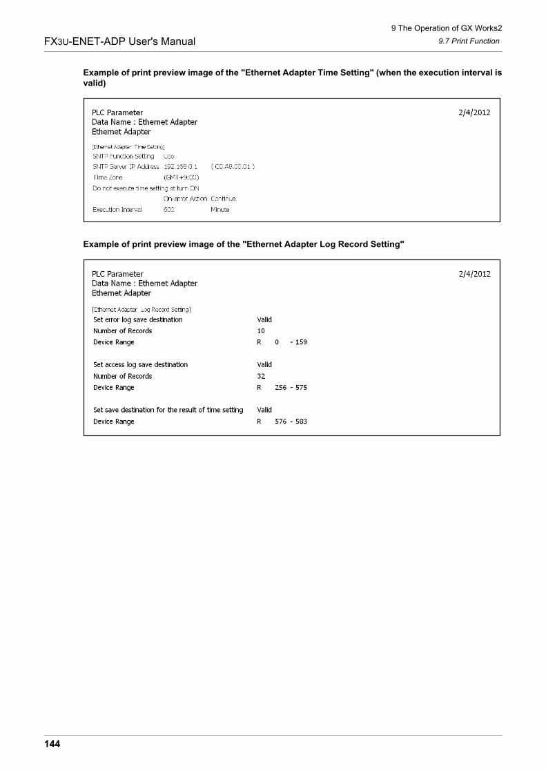
9 The Operation of GX Works2
9.7 Print Function
144
FX3U-ENET-ADP User's Manual
Example of print preview image of the "Ethernet Adapter Time Setting" (when the execution interval isvalid)
Example of print preview image of the "Ethernet Adapter Log Record Setting"
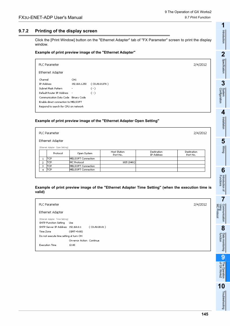
9 The Operation of GX Works2
9.7 Print Function
145
FX3U-ENET-ADP User's Manual
1
Introduction
2
Specification
3
System
C
onfiguration
4
Installation
5
Wiring
6
Introduction of F
unctions
7
Com
munication
Using
MC
Protocol
8
Data m
onitoring function
9
The O
peration of G
X W
orks2
10
Troubleshooting
9.7.2 Printing of the display screen
Click the [Print Window] button on the "Ethernet Adapter" tab of "FX Parameter" screen to print the displaywindow.
Example of print preview image of the "Ethernet Adapter"
Example of print preview image of the "Ethernet Adapter Open Setting"
Example of print preview image of the "Ethernet Adapter Time Setting" (when the execution time isvalid)
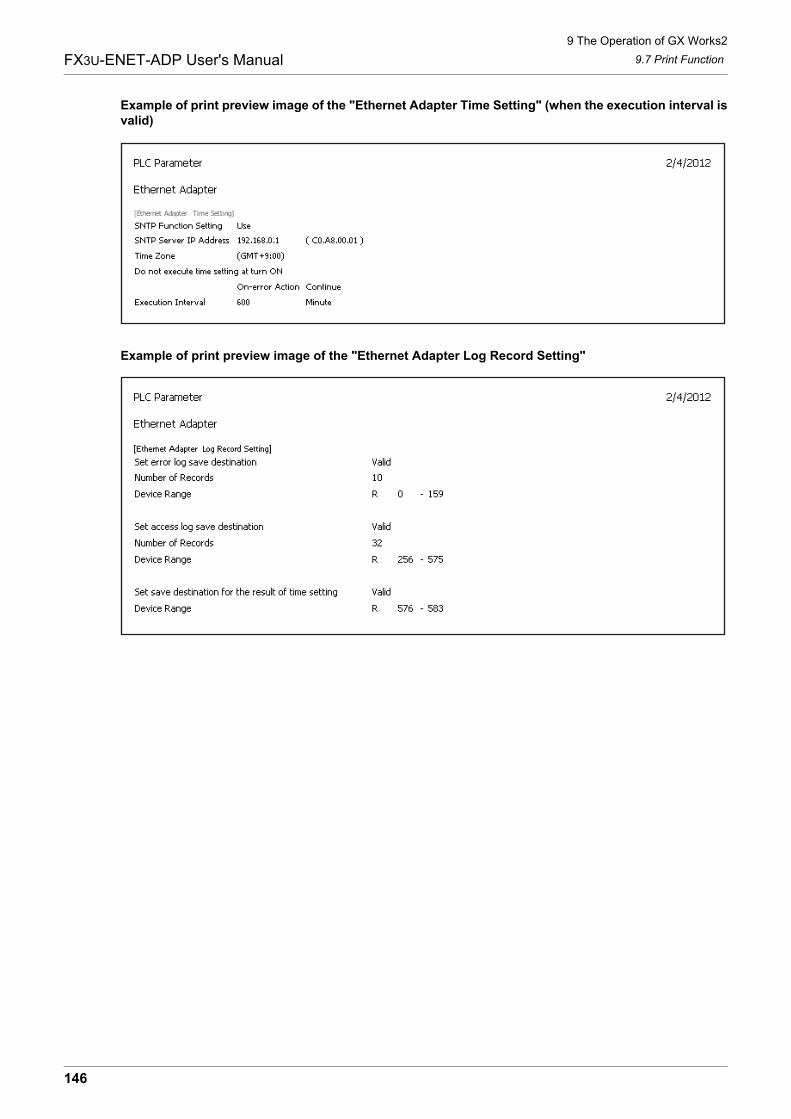
9 The Operation of GX Works2
9.7 Print Function
146
FX3U-ENET-ADP User's Manual
Example of print preview image of the "Ethernet Adapter Time Setting" (when the execution interval isvalid)
Example of print preview image of the "Ethernet Adapter Log Record Setting"
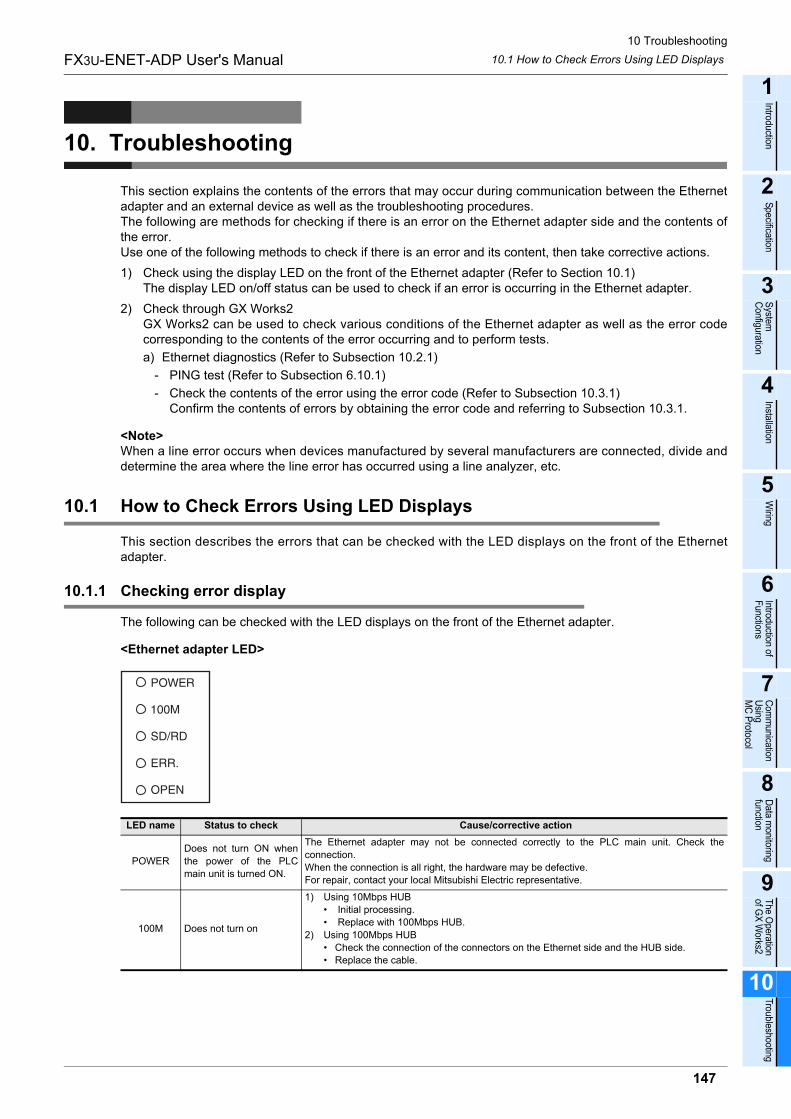
10 Troubleshooting
10.1 How to Check Errors Using LED Displays
147
FX3U-ENET-ADP User's Manual
1
Introduction
2
Specification
3
System
C
onfiguration
4
Installation
5
Wiring
6
Introduction of F
unctions
7
Com
munication
Using
MC
Protocol
8
Data m
onitoring function
9
The O
peration of G
X W
orks2
10
Troubleshooting
10. Troubleshooting
This section explains the contents of the errors that may occur during communication between the Ethernetadapter and an external device as well as the troubleshooting procedures.The following are methods for checking if there is an error on the Ethernet adapter side and the contents ofthe error.Use one of the following methods to check if there is an error and its content, then take corrective actions.
1) Check using the display LED on the front of the Ethernet adapter (Refer to Section 10.1)The display LED on/off status can be used to check if an error is occurring in the Ethernet adapter.
2) Check through GX Works2GX Works2 can be used to check various conditions of the Ethernet adapter as well as the error codecorresponding to the contents of the error occurring and to perform tests.
a) Ethernet diagnostics (Refer to Subsection 10.2.1)
- PING test (Refer to Subsection 6.10.1)
- Check the contents of the error using the error code (Refer to Subsection 10.3.1)Confirm the contents of errors by obtaining the error code and referring to Subsection 10.3.1.
<Note>When a line error occurs when devices manufactured by several manufacturers are connected, divide anddetermine the area where the line error has occurred using a line analyzer, etc.
10.1 How to Check Errors Using LED Displays
This section describes the errors that can be checked with the LED displays on the front of the Ethernetadapter.
10.1.1 Checking error display
The following can be checked with the LED displays on the front of the Ethernet adapter.
<Ethernet adapter LED>
LED name Status to check Cause/corrective action
POWER
Does not turn ON when
the power of the PLC
main unit is turned ON.
The Ethernet adapter may not be connected correctly to the PLC main unit. Check the
connection.
When the connection is all right, the hardware may be defective.
For repair, contact your local Mitsubishi Electric representative.
100M Does not turn on
1) Using 10Mbps HUB
� Initial processing.
� Replace with 100Mbps HUB.
2) Using 100Mbps HUB
� Check the connection of the connectors on the Ethernet side and the HUB side.
� Replace the cable.
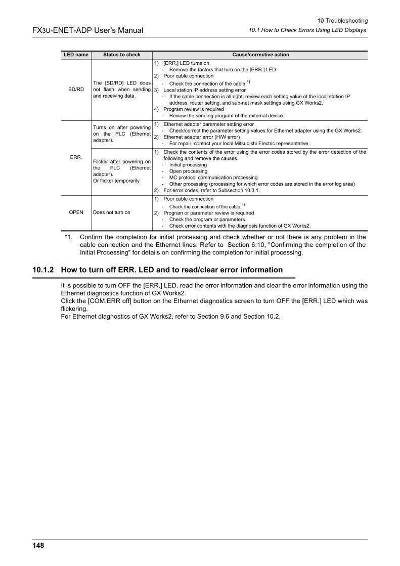
10 Troubleshooting
10.1 How to Check Errors Using LED Displays
148
FX3U-ENET-ADP User's Manual
*1. Confirm the completion for initial processing and check whether or not there is any problem in thecable connection and the Ethernet lines. Refer to Section 6.10, "Confirming the completion of theInitial Processing" for details on confirming the completion for initial processing.
10.1.2 How to turn off ERR. LED and to read/clear error information
It is possible to turn OFF the [ERR.] LED, read the error information and clear the error information using theEthernet diagnostics function of GX Works2.Click the [COM.ERR off] button on the Ethernet diagnostics screen to turn OFF the [ERR.] LED which wasflickering.For Ethernet diagnostics of GX Works2, refer to Section 9.6 and Section 10.2.
SD/RD
The [SD/RD] LED does
not flash when sending
and receiving data.
1) [ERR.] LED turns on.
- Remove the factors that turn on the [ERR.] LED.
2) Poor cable connection
- Check the connection of the cable.*1
3) Local station IP address setting error
- If the cable connection is all right, review each setting value of the local station IP
address, router setting, and sub-net mask settings using GX Works2.
4) Program review is required
- Review the sending program of the external device.
ERR.
Turns on after powering
on the PLC (Ethernet
adapter).
1) Ethernet adapter parameter setting error
- Check/correct the parameter setting values for Ethernet adapter using the GX Works2.
2) Ethernet adapter error (H/W error)
- For repair, contact your local Mitsubishi Electric representative.
Flicker after powering on
the PLC (Ethernet
adapter).
Or flicker temporarily
1) Check the contents of the error using the error codes stored by the error detection of the
following and remove the causes.
- Initial processing
- Open processing
- MC protocol communication processing
- Other processing (processing for which error codes are stored in the error log area)
2) For error codes, refer to Subsection 10.3.1.
OPEN Does not turn on
1) Poor cable connection
- Check the connection of the cable.*1
2) Program or parameter review is required
- Check the program or parameters.
- Check error contents with the diagnosis function of GX Works2.
LED name Status to check Cause/corrective action
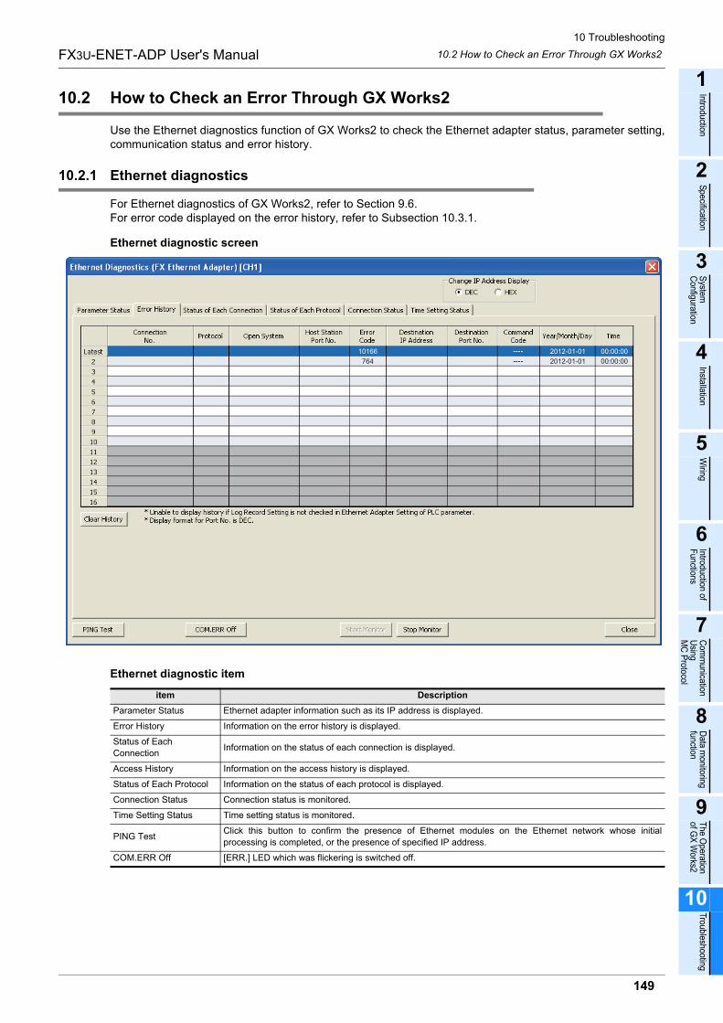
10 Troubleshooting
10.2 How to Check an Error Through GX Works2
149
FX3U-ENET-ADP User's Manual
1
Introduction
2
Specification
3
System
C
onfiguration
4
Installation
5
Wiring
6
Introduction of F
unctions
7
Com
munication
Using
MC
Protocol
8
Data m
onitoring function
9
The O
peration of G
X W
orks2
10
Troubleshooting
10.2 How to Check an Error Through GX Works2
Use the Ethernet diagnostics function of GX Works2 to check the Ethernet adapter status, parameter setting,communication status and error history.
10.2.1 Ethernet diagnostics
For Ethernet diagnostics of GX Works2, refer to Section 9.6.For error code displayed on the error history, refer to Subsection 10.3.1.
Ethernet diagnostic screen
Ethernet diagnostic item
item Description
Parameter Status Ethernet adapter information such as its IP address is displayed.
Error History Information on the error history is displayed.
Status of Each
ConnectionInformation on the status of each connection is displayed.
Access History Information on the access history is displayed.
Status of Each Protocol Information on the status of each protocol is displayed.
Connection Status Connection status is monitored.
Time Setting Status Time setting status is monitored.
PING TestClick this button to confirm the presence of Ethernet modules on the Ethernet network whose initial
processing is completed, or the presence of specified IP address.
COM.ERR Off [ERR.] LED which was flickering is switched off.
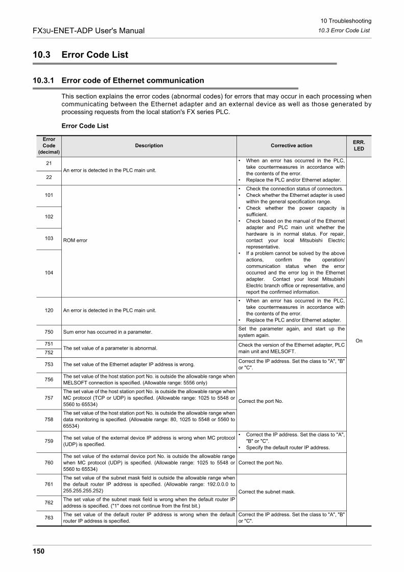
10 Troubleshooting
10.3 Error Code List
150
FX3U-ENET-ADP User's Manual
10.3 Error Code List
10.3.1 Error code of Ethernet communication
This section explains the error codes (abnormal codes) for errors that may occur in each processing whencommunicating between the Ethernet adapter and an external device as well as those generated byprocessing requests from the local station's FX series PLC.
Error Code List
Error
Code
(decimal)
Description Corrective actionERR.
LED
21
An error is detected in the PLC main unit.
� When an error has occurred in the PLC,
take countermeasures in accordance with
the contents of the error.
� Replace the PLC and/or Ethernet adapter.
On
22
101
ROM error
� Check the connection status of connectors.
� Check whether the Ethernet adapter is used
within the general specification range.
� Check whether the power capacity is
sufficient.
� Check based on the manual of the Ethernet
adapter and PLC main unit whether the
hardware is in normal status. For repair,
contact your local Mitsubishi Electric
representative.
� If a problem cannot be solved by the above
actions, confirm the operation/
communication status when the error
occurred and the error log in the Ethernet
adapter. Contact your local Mitsubishi
Electric branch office or representative, and
report the confirmed information.
102
103
104
120 An error is detected in the PLC main unit.
� When an error has occurred in the PLC,
take countermeasures in accordance with
the contents of the error.
� Replace the PLC and/or Ethernet adapter.
750 Sum error has occurred in a parameter.Set the parameter again, and start up the
system again.
751The set value of a parameter is abnormal.
Check the version of the Ethernet adapter, PLC
main unit and MELSOFT.752
753 The set value of the Ethernet adapter IP address is wrong.Correct the IP address. Set the class to "A", "B"
or "C".
756The set value of the host station port No. is outside the allowable range when
MELSOFT connection is specified. (Allowable range: 5556 only)
Correct the port No.757
The set value of the host station port No. is outside the allowable range when
MC protocol (TCP or UDP) is specified. (Allowable range: 1025 to 5548 or
5560 to 65534)
758
The set value of the host station port No. is outside the allowable range when
data monitoring is specified. (Allowable range: 80, 1025 to 5548 or 5560 to
65534)
759The set value of the external device IP address is wrong when MC protocol
(UDP) is specified.
� Correct the IP address. Set the class to "A",
"B" or "C".
� Specify the default router IP address.
760
The set value of the external device port No. is outside the allowable range
when MC protocol (UDP) is specified. (Allowable range: 1025 to 5548 or
5560 to 65534)
Correct the port No.
761
The set value of the subnet mask field is outside the allowable range when
the default router IP address is specified. (Allowable range: 192.0.0.0 to
255.255.255.252) Correct the subnet mask.
762The set value of the subnet mask field is wrong when the default router IP
address is specified. ("1" does not continue from the first bit.)
763The set value of the default router IP address is wrong when the default
router IP address is specified.
Correct the IP address. Set the class to "A", "B"
or "C".
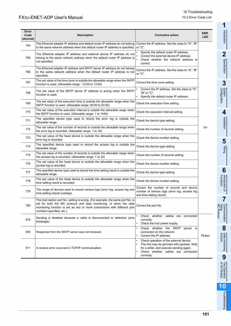
10 Troubleshooting
10.3 Error Code List
151
FX3U-ENET-ADP User's Manual
1
Introduction
2
Specification
3
System
C
onfiguration
4
Installation
5
Wiring
6
Introduction of F
unctions
7
Com
munication
Using
MC
Protocol
8
Data m
onitoring function
9
The O
peration of G
X W
orks2
10
Troubleshooting
764The Ethernet adapter IP address and default router IP address do not belong
to the same network address when the default router IP address is specified.
Correct the IP address. Set the class to "A", "B"
or "C".
On
765
The Ethernet adapter IP address and external device IP address do not
belong to the same network address when the default router IP address is
not specified.
� Specify the default router IP address.
� Correct the external device IP address.
� Check whether the network address is
correct.
766
The Ethernet adapter IP address and SNTP server IP address do not belong
to the same network address when the default router IP address is not
specified.
Correct the IP address. Set the class to "A", "B"
or "C".
767The set value of the time zone is outside the allowable range when the SNTP
function is used. (Allowable range: -12:00 to 13:00)Correct the time zone setting.
768The set value of the SNTP server IP address is wrong when the SNTP
function is used.
� Correct the IP address. Set the class to "A",
"B" or "C".
� Specify the default router IP address.
769The set value of the execution time is outside the allowable range when the
SNTP function is used. (Allowable range: 00:00 to 23:30)Check the execution time setting.
770The set value of the execution interval is outside the allowable range when
the SNTP function is used. (Allowable range: 1 to 1440)Check the execution interval setting.
771The specified device type used to record the error log is outside the
allowable range.Check the device type setting.
772The set value of the number of records is outside the allowable range when
the error log is recorded. (Allowable range: 1 to 16)Check the number of records setting.
773The set value of the head device is outside the allowable range when the
error log is recorded.Check the device number setting.
774The specified device type used to record the access log is outside the
allowable range.Check the device type setting.
775The set value of the number of records is outside the allowable range when
the access log is recorded. (Allowable range: 1 to 32)Check the number of records setting.
776The set value of the head device is outside the allowable range when the
access log is recorded.Check the device number setting.
777The specified device type used to record the time setting result is outside the
allowable range.Check the device type setting.
778The set value of the head device is outside the allowable range when the
time setting result is recorded.Check the device number setting.
779The range of devices used to record various logs (error log, access log and
time setting result) overlaps.
Correct the number of records and device
number of various logs (error log, access log
and time setting result).
780
The host station port No. setting is wrong. (For example, the same port No. is
set for both the MC protocol and data monitoring, or when the data
monitoring function is set as two or more connections with different port
numbers specified, etc.)
Correct the port No.
815Sending is disabled because a cable is disconnected or defective (wire
breakage).
� Check whether cables are connected
correctly.
� Check the hub power supply.
Flicker
850 Response from the SNTP server was not received.
� Check whether the SNTP server is
connected on the network.
� Correct the IP address.
911 A receive error occurred in TCP/IP communication.
� Check operation of the external device.
� The line may be jammed with packets. Wait
for a while, and execute sending again.
� Check whether cables are connected
correctly.
Error
Code
(decimal)
Description Corrective actionERR.
LED
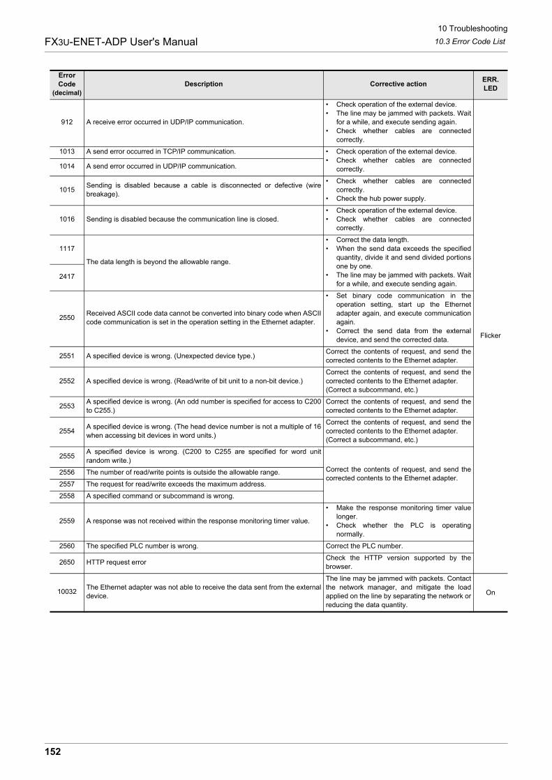
10 Troubleshooting
10.3 Error Code List
152
FX3U-ENET-ADP User's Manual
912 A receive error occurred in UDP/IP communication.
� Check operation of the external device.
� The line may be jammed with packets. Wait
for a while, and execute sending again.
� Check whether cables are connected
correctly.
Flicker
1013 A send error occurred in TCP/IP communication. � Check operation of the external device.
� Check whether cables are connected
correctly.1014 A send error occurred in UDP/IP communication.
1015Sending is disabled because a cable is disconnected or defective (wire
breakage).
� Check whether cables are connected
correctly.
� Check the hub power supply.
1016 Sending is disabled because the communication line is closed.
� Check operation of the external device.
� Check whether cables are connected
correctly.
1117
The data length is beyond the allowable range.
� Correct the data length.
� When the send data exceeds the specified
quantity, divide it and send divided portions
one by one.
� The line may be jammed with packets. Wait
for a while, and execute sending again.2417
2550Received ASCII code data cannot be converted into binary code when ASCII
code communication is set in the operation setting in the Ethernet adapter.
� Set binary code communication in the
operation setting, start up the Ethernet
adapter again, and execute communication
again.
� Correct the send data from the external
device, and send the corrected data.
2551 A specified device is wrong. (Unexpected device type.)Correct the contents of request, and send the
corrected contents to the Ethernet adapter.
2552 A specified device is wrong. (Read/write of bit unit to a non-bit device.)
Correct the contents of request, and send the
corrected contents to the Ethernet adapter.
(Correct a subcommand, etc.)
2553A specified device is wrong. (An odd number is specified for access to C200
to C255.)
Correct the contents of request, and send the
corrected contents to the Ethernet adapter.
2554A specified device is wrong. (The head device number is not a multiple of 16
when accessing bit devices in word units.)
Correct the contents of request, and send the
corrected contents to the Ethernet adapter.
(Correct a subcommand, etc.)
2555A specified device is wrong. (C200 to C255 are specified for word unit
random write.)
Correct the contents of request, and send the
corrected contents to the Ethernet adapter.2556 The number of read/write points is outside the allowable range.
2557 The request for read/write exceeds the maximum address.
2558 A specified command or subcommand is wrong.
2559 A response was not received within the response monitoring timer value.
� Make the response monitoring timer value
longer.
� Check whether the PLC is operating
normally.
2560 The specified PLC number is wrong. Correct the PLC number.
2650 HTTP request errorCheck the HTTP version supported by the
browser.
10032The Ethernet adapter was not able to receive the data sent from the external
device.
The line may be jammed with packets. Contact
the network manager, and mitigate the load
applied on the line by separating the network or
reducing the data quantity.
On
Error
Code
(decimal)
Description Corrective actionERR.
LED
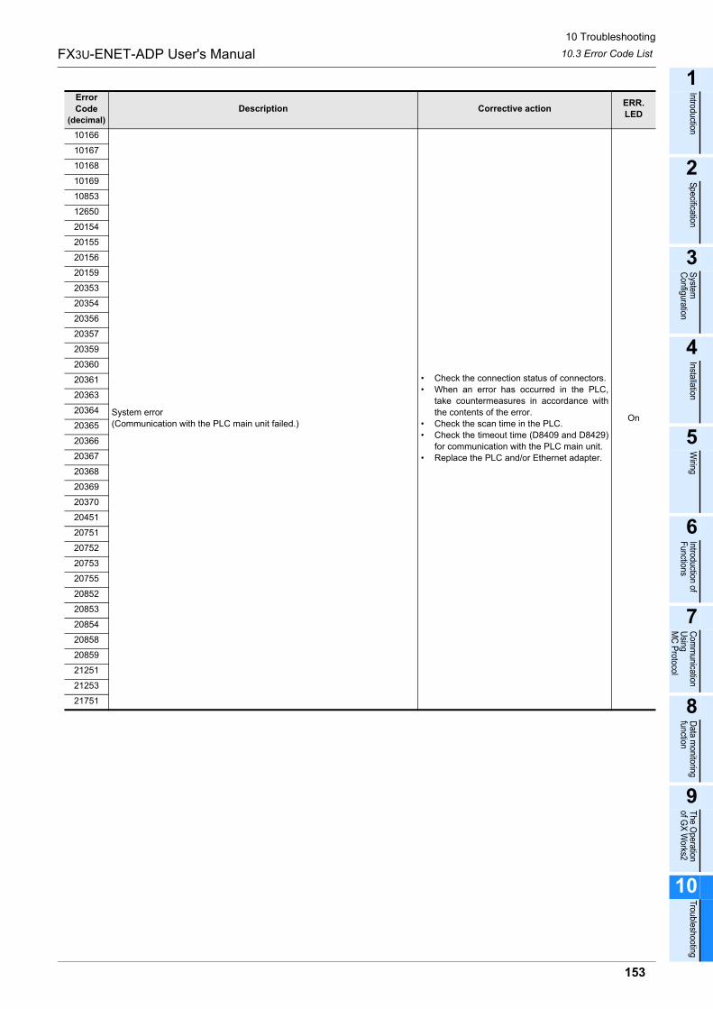
10 Troubleshooting
10.3 Error Code List
153
FX3U-ENET-ADP User's Manual
1
Introduction
2
Specification
3
System
C
onfiguration
4
Installation
5
Wiring
6
Introduction of F
unctions
7
Com
munication
Using
MC
Protocol
8
Data m
onitoring function
9
The O
peration of G
X W
orks2
10
Troubleshooting
10166
System error
(Communication with the PLC main unit failed.)
� Check the connection status of connectors.
� When an error has occurred in the PLC,
take countermeasures in accordance with
the contents of the error.
� Check the scan time in the PLC.
� Check the timeout time (D8409 and D8429)
for communication with the PLC main unit.
� Replace the PLC and/or Ethernet adapter.
On
10167
10168
10169
10853
12650
20154
20155
20156
20159
20353
20354
20356
20357
20359
20360
20361
20363
20364
20365
20366
20367
20368
20369
20370
20451
20751
20752
20753
20755
20852
20853
20854
20858
20859
21251
21253
21751
Error
Code
(decimal)
Description Corrective actionERR.
LED
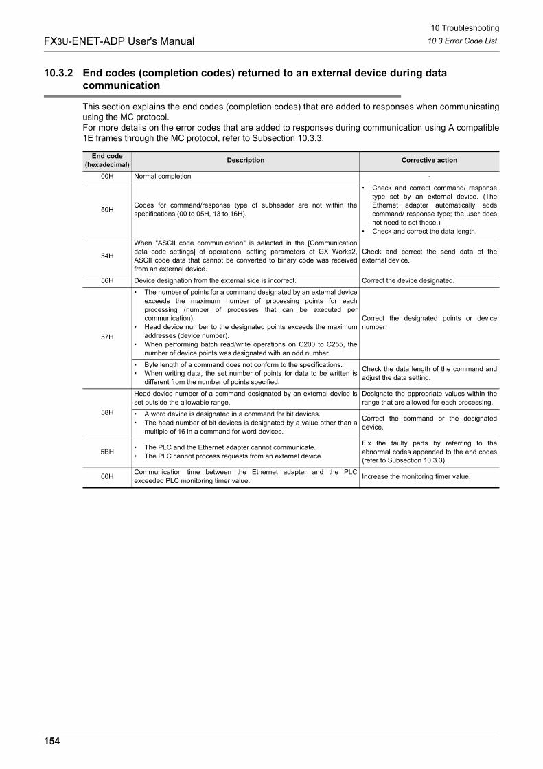
10 Troubleshooting
10.3 Error Code List
154
FX3U-ENET-ADP User's Manual
10.3.2 End codes (completion codes) returned to an external device during data communication
This section explains the end codes (completion codes) that are added to responses when communicatingusing the MC protocol.For more details on the error codes that are added to responses during communication using A compatible1E frames through the MC protocol, refer to Subsection 10.3.3.
End code
(hexadecimal)Description Corrective action
00H Normal completion -
50HCodes for command/response type of subheader are not within the
specifications (00 to 05H, 13 to 16H).
� Check and correct command/ response
type set by an external device. (The
Ethernet adapter automatically adds
command/ response type; the user does
not need to set these.)
� Check and correct the data length.
54H
When "ASCII code communication" is selected in the [Communication
data code settings] of operational setting parameters of GX Works2,
ASCII code data that cannot be converted to binary code was received
from an external device.
Check and correct the send data of the
external device.
56H Device designation from the external side is incorrect. Correct the device designated.
57H
� The number of points for a command designated by an external device
exceeds the maximum number of processing points for each
processing (number of processes that can be executed per
communication).
� Head device number to the designated points exceeds the maximum
addresses (device number).
� When performing batch read/write operations on C200 to C255, the
number of device points was designated with an odd number.
Correct the designated points or device
number.
� Byte length of a command does not conform to the specifications.
� When writing data, the set number of points for data to be written is
different from the number of points specified.
Check the data length of the command and
adjust the data setting.
58H
Head device number of a command designated by an external device is
set outside the allowable range.
Designate the appropriate values within the
range that are allowed for each processing.
� A word device is designated in a command for bit devices.
� The head number of bit devices is designated by a value other than a
multiple of 16 in a command for word devices.
Correct the command or the designated
device.
5BH� The PLC and the Ethernet adapter cannot communicate.
� The PLC cannot process requests from an external device.
Fix the faulty parts by referring to the
abnormal codes appended to the end codes
(refer to Subsection 10.3.3).
60HCommunication time between the Ethernet adapter and the PLC
exceeded PLC monitoring timer value.Increase the monitoring timer value.
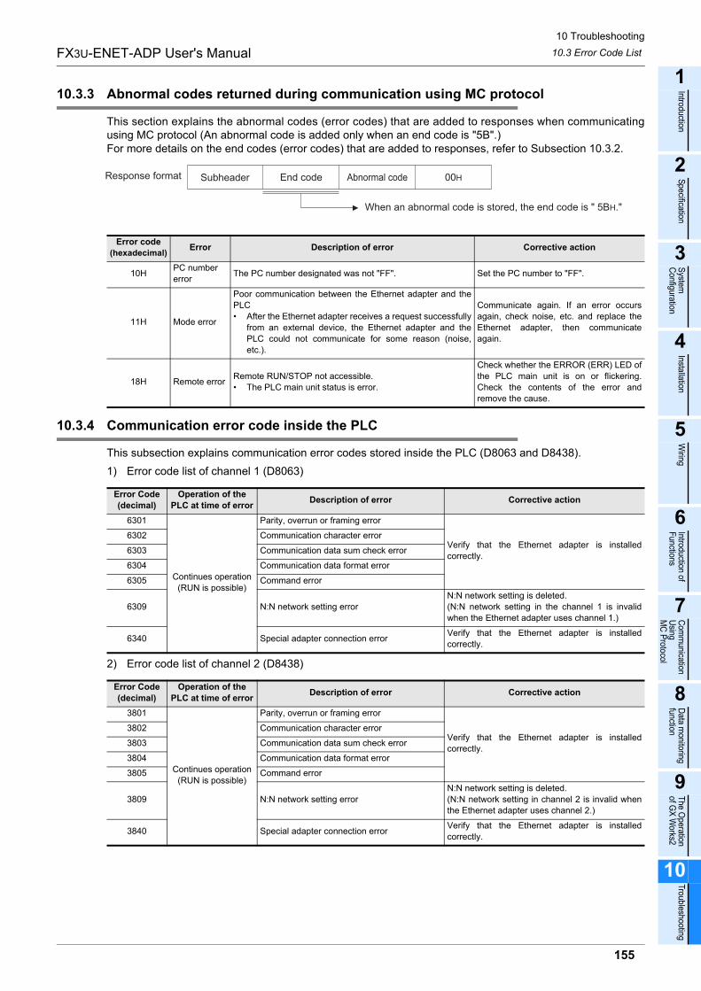
10 Troubleshooting
10.3 Error Code List
155
FX3U-ENET-ADP User's Manual
1
Introduction
2
Specification
3
System
C
onfiguration
4
Installation
5
Wiring
6
Introduction of F
unctions
7
Com
munication
Using
MC
Protocol
8
Data m
onitoring function
9
The O
peration of G
X W
orks2
10
Troubleshooting
10.3.3 Abnormal codes returned during communication using MC protocol
This section explains the abnormal codes (error codes) that are added to responses when communicatingusing MC protocol (An abnormal code is added only when an end code is "5B".)For more details on the end codes (error codes) that are added to responses, refer to Subsection 10.3.2.
10.3.4 Communication error code inside the PLC
This subsection explains communication error codes stored inside the PLC (D8063 and D8438).
1) Error code list of channel 1 (D8063)
2) Error code list of channel 2 (D8438)
Error code
(hexadecimal)Error Description of error Corrective action
10HPC number
errorThe PC number designated was not "FF". Set the PC number to "FF".
11H Mode error
Poor communication between the Ethernet adapter and the
PLC
� After the Ethernet adapter receives a request successfully
from an external device, the Ethernet adapter and the
PLC could not communicate for some reason (noise,
etc.).
Communicate again. If an error occurs
again, check noise, etc. and replace the
Ethernet adapter, then communicate
again.
18H Remote errorRemote RUN/STOP not accessible.
� The PLC main unit status is error.
Check whether the ERROR (ERR) LED of
the PLC main unit is on or flickering.
Check the contents of the error and
remove the cause.
Error Code
(decimal)
Operation of the
PLC at time of errorDescription of error Corrective action
6301
Continues operation
(RUN is possible)
Parity, overrun or framing error
Verify that the Ethernet adapter is installed
correctly.
6302 Communication character error
6303 Communication data sum check error
6304 Communication data format error
6305 Command error
6309 N:N network setting error
N:N network setting is deleted.
(N:N network setting in the channel 1 is invalid
when the Ethernet adapter uses channel 1.)
6340 Special adapter connection errorVerify that the Ethernet adapter is installed
correctly.
Error Code
(decimal)
Operation of the
PLC at time of errorDescription of error Corrective action
3801
Continues operation
(RUN is possible)
Parity, overrun or framing error
Verify that the Ethernet adapter is installed
correctly.
3802 Communication character error
3803 Communication data sum check error
3804 Communication data format error
3805 Command error
3809 N:N network setting error
N:N network setting is deleted.
(N:N network setting in channel 2 is invalid when
the Ethernet adapter uses channel 2.)
3840 Special adapter connection errorVerify that the Ethernet adapter is installed
correctly.
00HAbnormal codeResponse format Subheader End code
When an abnormal code is stored, the end code is " 5BH."
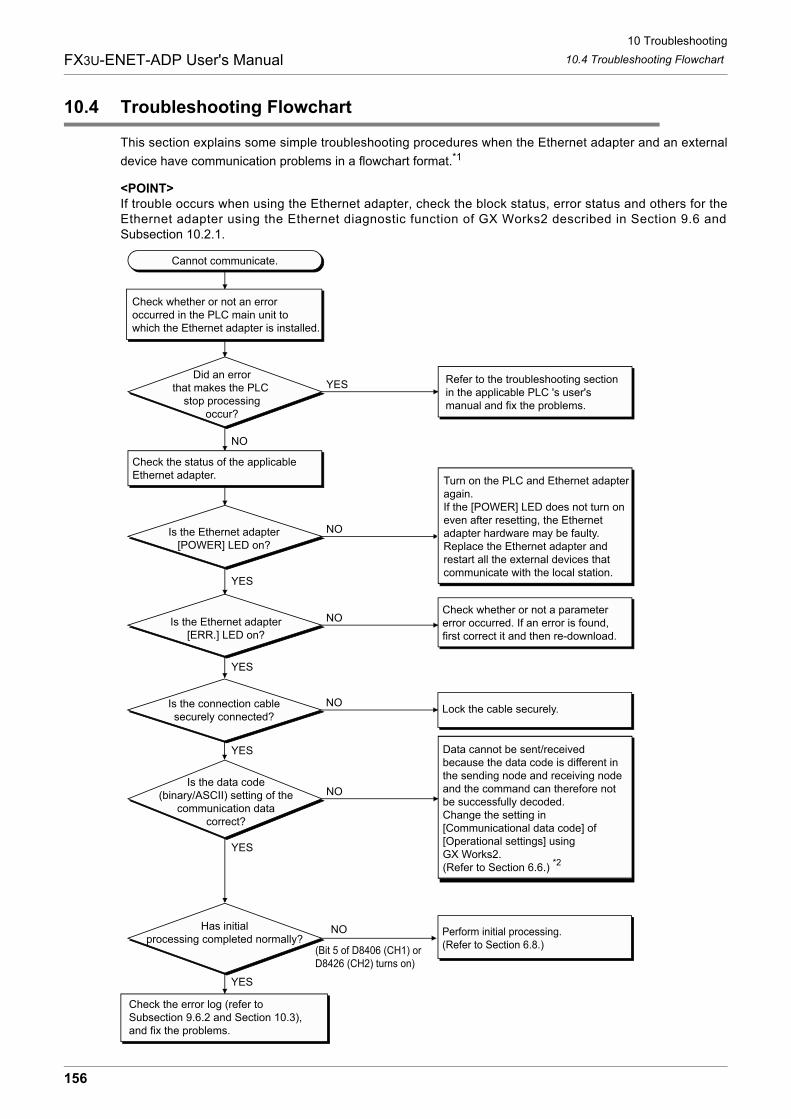
10 Troubleshooting
10.4 Troubleshooting Flowchart
156
FX3U-ENET-ADP User's Manual
10.4 Troubleshooting Flowchart
This section explains some simple troubleshooting procedures when the Ethernet adapter and an external
device have communication problems in a flowchart format.*1
<POINT>If trouble occurs when using the Ethernet adapter, check the block status, error status and others for theEthernet adapter using the Ethernet diagnostic function of GX Works2 described in Section 9.6 andSubsection 10.2.1.
Cannot communicate.
Check whether or not an erroroccurred in the PLC main unit to which the Ethernet adapter is installed.
Did an errorthat makes the PLC
stop processingoccur?
Check the status of the applicableEthernet adapter.
Refer to the troubleshooting sectionin the applicable PLC 's user'smanual and fix the problems.
YES
NO
Is the Ethernet adapter[POWER] LED on?
NO
YES
YES
YES
Is the connection cablesecurely connected?
NOLock the cable securely.
Is the Ethernet adapter[ERR.] LED on?
Check whether or not a parameter error occurred. If an error is found,first correct it and then re-download.
NO
Is the data code(binary/ASCII) setting of the
communication datacorrect?
NO
YES
Data cannot be sent/receivedbecause the data code is different in the sending node and receiving nodeand the command can therefore notbe successfully decoded.Change the setting in[Communicational data code] of[Operational settings] using GX Works2. (Refer to Section 6.6.)
*2
Turn on the PLC and Ethernet adapter again.If the [POWER] LED does not turn oneven after resetting, the Ethernetadapter hardware may be faulty.Replace the Ethernet adapter andrestart all the external devices thatcommunicate with the local station.
Has initialprocessing completed normally?
NO
(Bit 5 of D8406 (CH1) or D8426 (CH2) turns on)
YES
Check the error log (refer to Subsection 9.6.2 and Section 10.3), and fix the problems.
Perform initial processing.(Refer to Section 6.8.)
10 Troubleshooting
10.4 Troubleshooting Flowchart
157
FX3U-ENET-ADP User's Manual
1
Introduction
2
Specification
3
System
C
onfiguration
4
Installation
5
Wiring
6
Introduction of F
unctions
7
Com
munication
Using
MC
Protocol
8
Data m
onitoring function
9
The O
peration of G
X W
orks2
10
Troubleshooting
*1. If [ERR.] LED turns ON, refer to Section 10.1. When an error is shown in the Error history (refer to Subsection 9.6.2) offered by the Ethernetdiagnostics function of GX Works2, check the error code, and check the contents of the error and takecountermeasures in accordance with Subsection 10.3.1.
*2. Error codes not found in the error code list may be returned to the external device side if thecommunication data settings on the Ethernet adapter side (refer to Section 6.6) and the data codesettings on the external device side are different. The Ethernet adapter cannot decode commands correctly if data with different data codes is received.The Ethernet adapter returns error responses according to the communication data code settings.
<POINT>
1) When the Ethernet adapter is replaced due to an error, reboot the following external devices and restartdata communication: (If the external device retains the Ethernet address, it may be impossible to continue communicationbecause when a adapter is replaced the Ethernet address changes.) Similarly, when the external device (personal computer, etc.) is replaced, restart the Ethernet adapter(PLC).
- All external devices that communicated with the station whose Ethernet adapter was replaced.
- All external devices that communicated with other stations' PLC via a station whose Ethernet adapter was replaced.
2) When connecting a device to the Ethernet adapter, see the following sections for the required devicesand connection method:Section 3.2: Devices Required for Network ConfigurationSection 5.3: Connecting to the Network
3) When the Ethernet adapter often cannot receive messages sent from an external device (that is, whenthe error log is long), it may be that considerable load is applied on the Ethernet network due to datacommunication among connected devices.To reduce the load to the Ethernet line, it is necessary to take corrective measures such as dividing thenetwork or reducing the data transmission frequency.Consult your network administrator and take appropriate measures.
4) If the ground terminals of the Ethernet adapter are not set, the communication line is closed(disconnected) due to the effects of noise, and as a result there may be no communication with externaldevices.
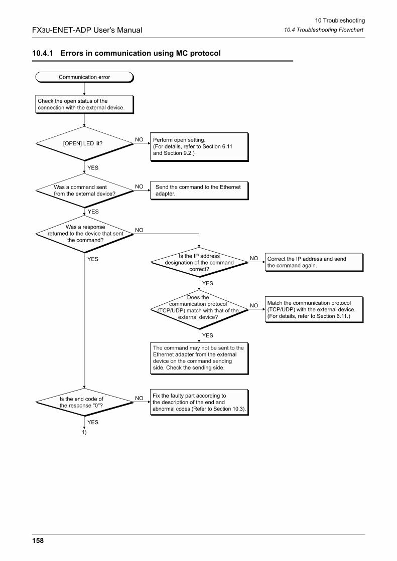
10 Troubleshooting
10.4 Troubleshooting Flowchart
158
FX3U-ENET-ADP User's Manual
10.4.1 Errors in communication using MC protocol
Communication error
Check the open status of the connection with the external device.
[OPEN] LED lit?NO
YES
NO
YES
Send the command to the Ethernet adapter.
Was a responsereturned to the device that sent
the command?
NO
YES
YES
1)
Perform open setting.(For details, refer to Section 6.11 and Section 9.2.)
Is the IP addressdesignation of the command
correct?
NO
YES
Correct the IP address and sendthe command again.
NO
YES
Match the communication protocol(TCP/UDP) with the external device.(For details, refer to Section 6.11.)
Is the end code ofthe response "0"?
NO Fix the faulty part according tothe description of the end andabnormal codes (Refer to Section 10.3).
Does thecommunication protocol
(TCP/UDP) match with that of theexternal device?
The command may not be sent to theEthernet adapter from the externaldevice on the command sending side. Check the sending side.
Was a command sentfrom the external device?
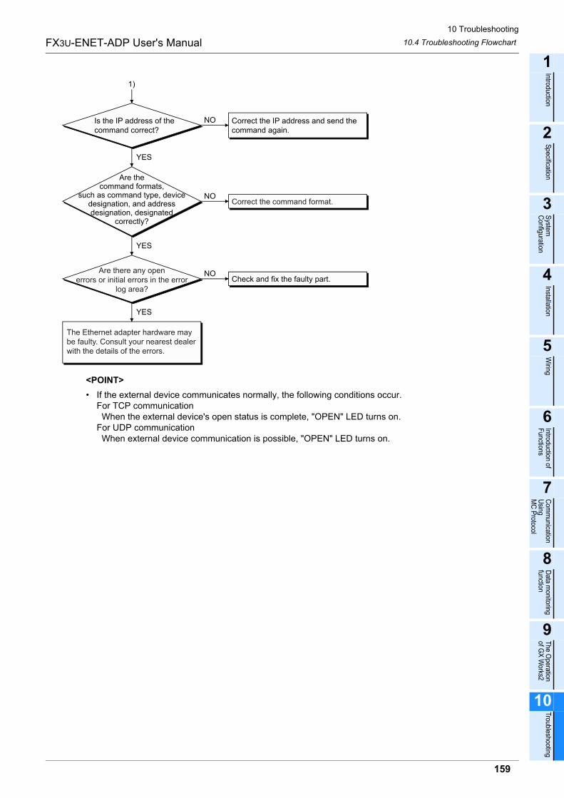
10 Troubleshooting
10.4 Troubleshooting Flowchart
159
FX3U-ENET-ADP User's Manual
1
Introduction
2
Specification
3
System
C
onfiguration
4
Installation
5
Wiring
6
Introduction of F
unctions
7
Com
munication
Using
MC
Protocol
8
Data m
onitoring function
9
The O
peration of G
X W
orks2
10
Troubleshooting
<POINT>
� If the external device communicates normally, the following conditions occur.For TCP communication When the external device's open status is complete, "OPEN" LED turns on.For UDP communication When external device communication is possible, "OPEN" LED turns on.
Is the IP address of thecommand correct?
NO
1)
Correct the IP address and send thecommand again.
YES
Are thecommand formats,
such as command type, devicedesignation, and addressdesignation, designated
correctly?
NO
YES
NO
YES
Check and fix the faulty part.
Correct the command format.
Are there any openerrors or initial errors in the error
log area?
The Ethernet adapter hardware maybe faulty. Consult your nearest dealerwith the details of the errors.
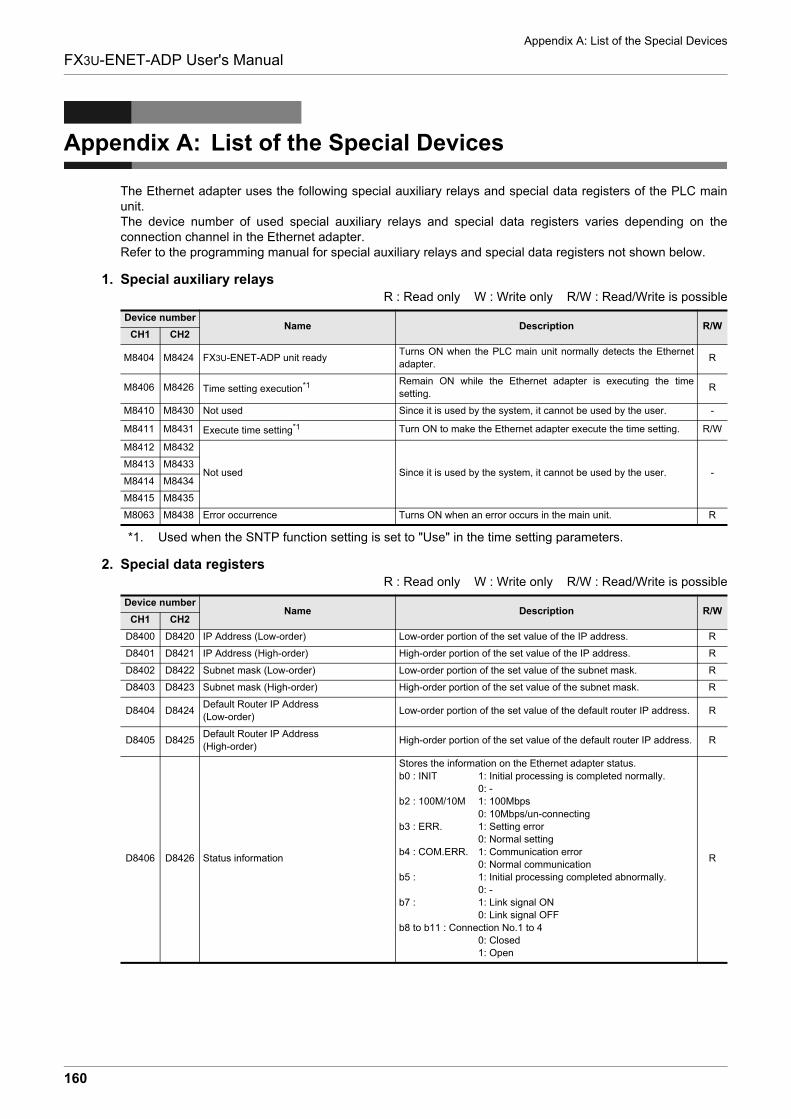
Appendix A: List of the Special Devices
160
FX3U-ENET-ADP User's Manual
Appendix A: List of the Special Devices
The Ethernet adapter uses the following special auxiliary relays and special data registers of the PLC mainunit.The device number of used special auxiliary relays and special data registers varies depending on theconnection channel in the Ethernet adapter.Refer to the programming manual for special auxiliary relays and special data registers not shown below.
1. Special auxiliary relaysR : Read only W : Write only R/W : Read/Write is possible
*1. Used when the SNTP function setting is set to "Use" in the time setting parameters.
2. Special data registersR : Read only W : Write only R/W : Read/Write is possible
Device numberName Description R/W
CH1 CH2
M8404 M8424 FX3U-ENET-ADP unit readyTurns ON when the PLC main unit normally detects the Ethernet
adapter.R
M8406 M8426 Time setting execution*1 Remain ON while the Ethernet adapter is executing the time
setting.R
M8410 M8430 Not used Since it is used by the system, it cannot be used by the user. -
M8411 M8431 Execute time setting*1 Turn ON to make the Ethernet adapter execute the time setting. R/W
M8412 M8432
Not used Since it is used by the system, it cannot be used by the user. -M8413 M8433
M8414 M8434
M8415 M8435
M8063 M8438 Error occurrence Turns ON when an error occurs in the main unit. R
Device numberName Description R/W
CH1 CH2
D8400 D8420 IP Address (Low-order) Low-order portion of the set value of the IP address. R
D8401 D8421 IP Address (High-order) High-order portion of the set value of the IP address. R
D8402 D8422 Subnet mask (Low-order) Low-order portion of the set value of the subnet mask. R
D8403 D8423 Subnet mask (High-order) High-order portion of the set value of the subnet mask. R
D8404 D8424Default Router IP Address
(Low-order)Low-order portion of the set value of the default router IP address. R
D8405 D8425Default Router IP Address
(High-order)High-order portion of the set value of the default router IP address. R
D8406 D8426 Status information
Stores the information on the Ethernet adapter status.
b0 : INIT 1: Initial processing is completed normally.
0: -
b2 : 100M/10M 1: 100Mbps
0: 10Mbps/un-connecting
b3 : ERR. 1: Setting error
0: Normal setting
b4 : COM.ERR. 1: Communication error
0: Normal communication
b5 : 1: Initial processing completed abnormally.
0: -
b7 : 1: Link signal ON
0: Link signal OFF
b8 to b11 : Connection No.1 to 4
0: Closed
1: Open
R
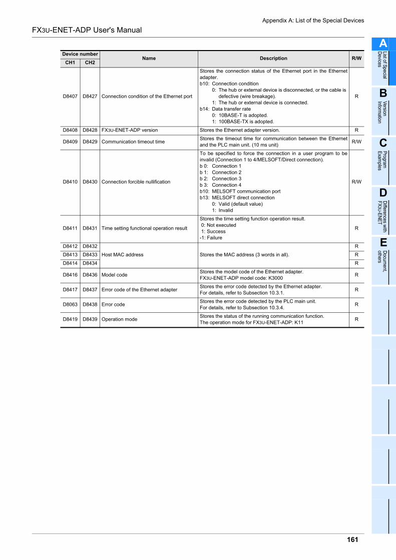
Appendix A: List of the Special Devices
161
FX3U-ENET-ADP User's Manual
A
List of Special
Devices
B
Version
Information
C
Program
E
xamples
D
Differences w
ith F
X3U
-EN
ET
E
Docum
ent, others
D8407 D8427 Connection condition of the Ethernet port
Stores the connection status of the Ethernet port in the Ethernet
adapter.
b10: Connection condition
0: The hub or external device is disconnected, or the cable is
defective (wire breakage).
1: The hub or external device is connected.
b14: Data transfer rate
0: 10BASE-T is adopted.
1: 100BASE-TX is adopted.
R
D8408 D8428 FX3U-ENET-ADP version Stores the Ethernet adapter version. R
D8409 D8429 Communication timeout timeStores the timeout time for communication between the Ethernet
and the PLC main unit. (10 ms unit)R/W
D8410 D8430 Connection forcible nullification
To be specified to force the connection in a user program to be
invalid (Connection 1 to 4/MELSOFT/Direct connection).
b 0: Connection 1
b 1: Connection 2
b 2: Connection 3
b 3: Connection 4
b10: MELSOFT communication port
b13: MELSOFT direct connection
0: Valid (default value)
1: Invalid
R/W
D8411 D8431 Time setting functional operation result
Stores the time setting function operation result.
0: Not executed
1: Success
-1: Failure
R
D8412 D8432
Host MAC address Stores the MAC address (3 words in all).
R
D8413 D8433 R
D8414 D8434 R
D8416 D8436 Model codeStores the model code of the Ethernet adapter.
FX3U-ENET-ADP model code: K3000R
D8417 D8437 Error code of the Ethernet adapterStores the error code detected by the Ethernet adapter.
For details, refer to Subsection 10.3.1.R
D8063 D8438 Error codeStores the error code detected by the PLC main unit.
For details, refer to Subsection 10.3.4.R
D8419 D8439 Operation modeStores the status of the running communication function.
The operation mode for FX3U-ENET-ADP: K11R
Device numberName Description R/W
CH1 CH2
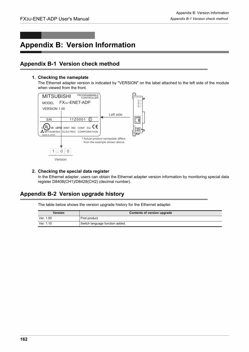
Appendix B: Version Information
Appendix B-1 Version check method
162
FX3U-ENET-ADP User's Manual
Appendix B: Version Information
Appendix B-1 Version check method
1. Checking the nameplateThe Ethernet adapter version is indicated by "VERSION" on the label attached to the left side of the modulewhen viewed from the front.
2. Checking the special data registerIn the Ethernet adapter, users can obtain the Ethernet adapter version information by monitoring special dataregister D8408(CH1)/D8428(CH2) (decimal number).
Appendix B-2 Version upgrade history
The table below shows the version upgrade history for the Ethernet adapter.
Version Contents of version upgrade
Ver. 1.00 First product
Ver. 1.10 Switch language function added.
Version
Left side
Actual product nameplate differs from the example shown above.
*
Appendix B: Version Information
Appendix B-2 Version upgrade history
163
FX3U-ENET-ADP User's Manual
A
List of Special
Devices
B
Version
Information
C
Program
E
xamples
D
Differences w
ith F
X3U
-EN
ET
E
Docum
ent, others
MEMO
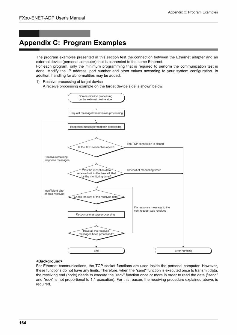
Appendix C: Program Examples
164
FX3U-ENET-ADP User's Manual
Appendix C: Program Examples
The program examples presented in this section test the connection between the Ethernet adapter and anexternal device (personal computer) that is connected to the same Ethernet.For each program, only the minimum programming that is required to perform the communication test isdone. Modify the IP address, port number and other values according to your system configuration. Inaddition, handling for abnormalities may be added.
1) Receive processing of target deviceA receive processing example on the target device side is shown below.
<Background>For Ethernet communications, the TCP socket functions are used inside the personal computer. However,these functions do not have any limits. Therefore, when the "send" function is executed once to transmit data,the receiving end (node) needs to execute the "recv" function once or more in order to read the data ("send"and "recv" is not proportional to 1:1 execution). For this reason, the receiving procedure explained above, isrequired.
Request message/transmission processing
Response message/reception processing
Is the TCP connection open?The TCP connection is closed
Timeout of monitoring timer
Error handlingEnd
If a response message to the next request was received
Receive remaining response messages
Insufficient size of data received
Check the size of the received data
Was the reception data received within the time allotted
by the monitoring timer?
Response message processing
Have all the received messages been processed?
Communication processing on the external device side
Appendix C: Program Examples
165
FX3U-ENET-ADP User's Manual
A
List of Special
Devices
B
Version
Information
C
Program
E
xamples
D
Differences w
ith F
X3U
-EN
ET
E
Docum
ent, others
Appendix C-1 Program example for communication using MC protocol -1
Appendix C-1 Program example for communication using MC protocol -1
The following explains a program example, its execution environment and the contents of datacommunication.
1) Execution environment of the program example
a) PLC side
- Main unit of the Ethernet installed station :FX3U/FX3UC
- Ethernet adapter No. : No.1
- Ethernet adapter IP address : 172.16.56.99 (AC.10.38.63H)
- Ethernet adapter port number : 10000
- GX Works2 setting
� Operational Settings :Refer to the following "3) GX Works2 setting a)"
� Open settings : Refer to the following "3) GX Works2 setting b)"
b) External device side
- Operation environment : Microsoft Windows 2000 Operating system
- Ethernet interface board model name : WINSOCK compatible board
- Library : WSOCK32.LIB
- Software development environment : Microsoft Corporation Visual C++ .NET
- Ethernet address : Setting not required because the ARP function is available
- IP address : Receive at Active open
- Port number : Receive at Active open
c) Communication protocol : TCP/IP
2) Outline of the program example
a) Sequence program on the PLC sideParameters are set from GX Works2.(Sequence program is not required)
b) Program on the external device sideExecutes the following read/write data communication with the PLC using the library mentionedabove.
- Write in word units (for 5 points from D0 to D4)
- Read in word units (for 5 points from D0 to D4)
3) GX Works2 settingsSet the PLC parameters as follows.
a) Operation settingsCommunication data code :ASCIIInitial timing : Always wait for OPEN (Communication possible at STOP time)IP address : 172.16.56.99 (AC.10.38.63H)
b) Open settingsProtocol : TCPOpen system : Unpassive (MC)Existence confirmation : No confirmLocal station Port No. : 10000
4) Program on the external device sideThe program example of the external device shown below accesses the FX3U/FX3UC of the station inwhich the Ethernet adapter is installed. When this program is executed, the contents of the following communication messages are displayed insequence:
a) Batch write command message in word units
b) Batch write response message in word units
c) Batch read command message in word units
d) Batch read response message in word units
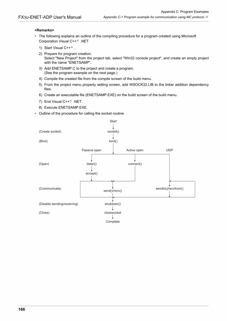
Appendix C: Program Examples
166
FX3U-ENET-ADP User's Manual Appendix C-1 Program example for communication using MC protocol -1
<Remarks>
� The following explains an outline of the compiling procedure for a program created using Microsoft
Corporation Visual C++ .NET
1) Start Visual C++ .
2) Prepare for program creation.Select "New Project" from the project tab, select "Win32 console project", and create an empty projectwith the name "ENETSAMP".
3) Add ENETSAMP.C to the project and create a program.(See the program example on the next page.)
4) Compile the created file from the compile screen of the build menu.
5) From the project menu property setting screen, add WSOCK32.LIB to the linker addition dependencyfiles.
6) Create an executable file (ENETSAMP.EXE) on the build screen of the build menu.
7) End Visual C++ .NET.
8) Execute ENETSAMP.EXE.
� Outline of the procedure for calling the socket routine
Start
socket()
bind()
Passive open Active open UDP
listen() connect()
accept()
send()/recv()sendto()/recvfrom()
shutdown()
closesocket
Complete
(Create socket)
(Bind)
(Open)
(Communicate)
(Disable sending/receiving)
(Close)
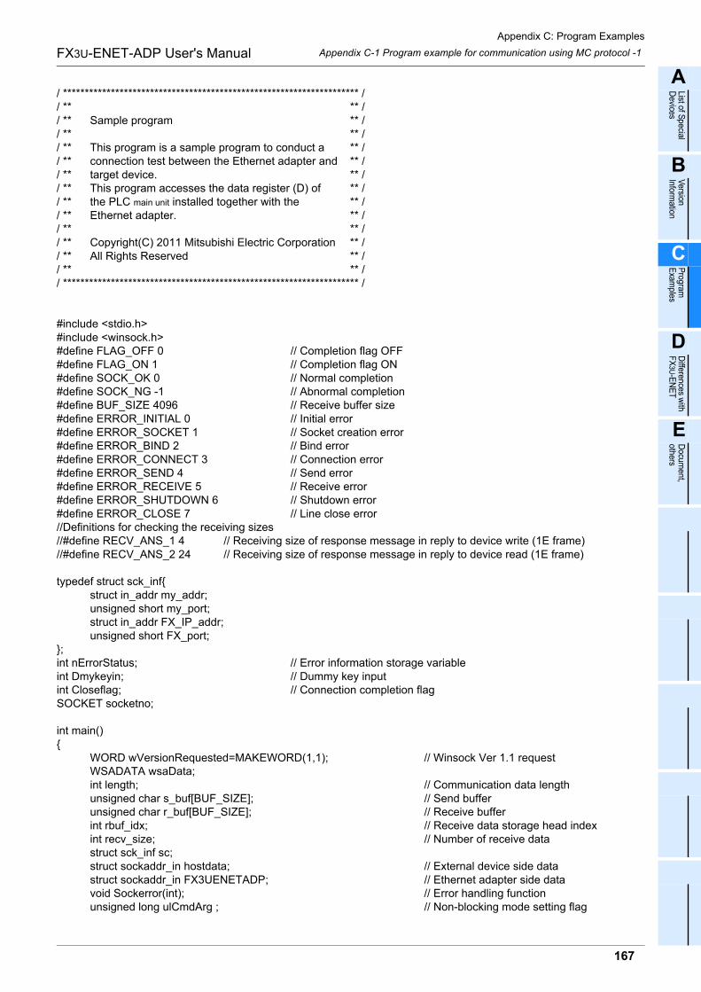
Appendix C: Program Examples
167
FX3U-ENET-ADP User's Manual
A
List of Special
Devices
B
Version
Information
C
Program
E
xamples
D
Differences w
ith F
X3U
-EN
ET
E
Docum
ent, others
Appendix C-1 Program example for communication using MC protocol -1
/ ******************************************************************** // ** ** // ** Sample program ** // ** ** // ** This program is a sample program to conduct a ** // ** connection test between the Ethernet adapter and ** // ** target device. ** // ** This program accesses the data register (D) of ** // ** the PLC main unit installed together with the ** // ** Ethernet adapter. ** // ** ** // ** Copyright(C) 2011 Mitsubishi Electric Corporation ** // ** All Rights Reserved ** // ** ** // ******************************************************************** /
#include <stdio.h>#include <winsock.h>#define FLAG_OFF 0 // Completion flag OFF#define FLAG_ON 1 // Completion flag ON#define SOCK_OK 0 // Normal completion#define SOCK_NG -1 // Abnormal completion#define BUF_SIZE 4096 // Receive buffer size#define ERROR_INITIAL 0 // Initial error#define ERROR_SOCKET 1 // Socket creation error#define ERROR_BIND 2 // Bind error#define ERROR_CONNECT 3 // Connection error#define ERROR_SEND 4 // Send error#define ERROR_RECEIVE 5 // Receive error#define ERROR_SHUTDOWN 6 // Shutdown error#define ERROR_CLOSE 7 // Line close error//Definitions for checking the receiving sizes//#define RECV_ANS_1 4 // Receiving size of response message in reply to device write (1E frame)//#define RECV_ANS_2 24 // Receiving size of response message in reply to device read (1E frame)
typedef struct sck_inf{struct in_addr my_addr;unsigned short my_port;struct in_addr FX_IP_addr;unsigned short FX_port;
};int nErrorStatus; // Error information storage variableint Dmykeyin; // Dummy key inputint Closeflag; // Connection completion flagSOCKET socketno;
int main(){
WORD wVersionRequested=MAKEWORD(1,1); // Winsock Ver 1.1 requestWSADATA wsaData;int length; // Communication data lengthunsigned char s_buf[BUF_SIZE]; // Send bufferunsigned char r_buf[BUF_SIZE]; // Receive bufferint rbuf_idx; // Receive data storage head indexint recv_size; // Number of receive datastruct sck_inf sc;struct sockaddr_in hostdata; // External device side datastruct sockaddr_in FX3UENETADP; // Ethernet adapter side datavoid Sockerror(int); // Error handling functionunsigned long ulCmdArg ; // Non-blocking mode setting flag
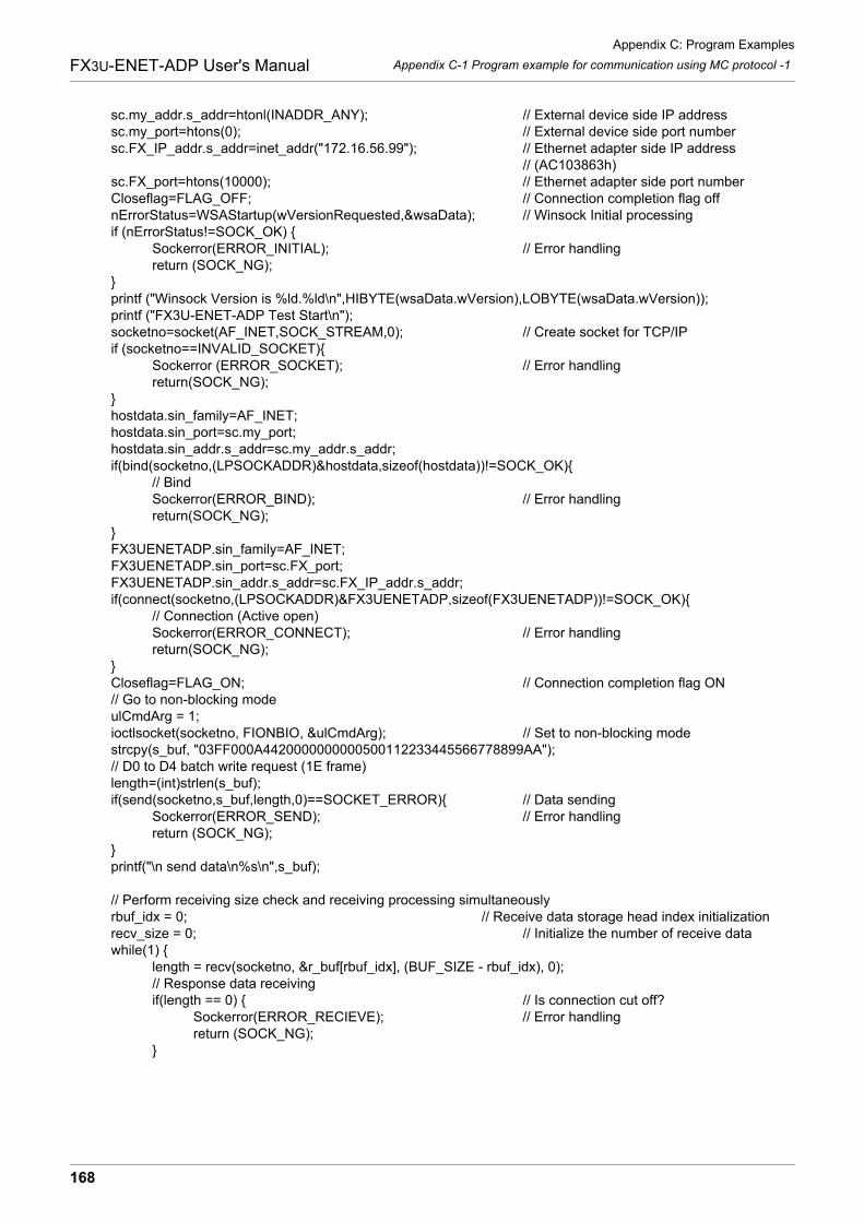
Appendix C: Program Examples
168
FX3U-ENET-ADP User's Manual Appendix C-1 Program example for communication using MC protocol -1
sc.my_addr.s_addr=htonl(INADDR_ANY); // External device side IP addresssc.my_port=htons(0); // External device side port numbersc.FX_IP_addr.s_addr=inet_addr("172.16.56.99"); // Ethernet adapter side IP address
// (AC103863h)sc.FX_port=htons(10000); // Ethernet adapter side port numberCloseflag=FLAG_OFF; // Connection completion flag offnErrorStatus=WSAStartup(wVersionRequested,&wsaData); // Winsock Initial processingif (nErrorStatus!=SOCK_OK) {
Sockerror(ERROR_INITIAL); // Error handlingreturn (SOCK_NG);
}printf ("Winsock Version is %ld.%ld\n",HIBYTE(wsaData.wVersion),LOBYTE(wsaData.wVersion));printf ("FX3U-ENET-ADP Test Start\n");socketno=socket(AF_INET,SOCK_STREAM,0); // Create socket for TCP/IPif (socketno==INVALID_SOCKET){
Sockerror (ERROR_SOCKET); // Error handlingreturn(SOCK_NG);
}hostdata.sin_family=AF_INET;hostdata.sin_port=sc.my_port;hostdata.sin_addr.s_addr=sc.my_addr.s_addr;if(bind(socketno,(LPSOCKADDR)&hostdata,sizeof(hostdata))!=SOCK_OK){
// BindSockerror(ERROR_BIND); // Error handlingreturn(SOCK_NG);
}FX3UENETADP.sin_family=AF_INET;FX3UENETADP.sin_port=sc.FX_port;FX3UENETADP.sin_addr.s_addr=sc.FX_IP_addr.s_addr;if(connect(socketno,(LPSOCKADDR)&FX3UENETADP,sizeof(FX3UENETADP))!=SOCK_OK){
// Connection (Active open)Sockerror(ERROR_CONNECT); // Error handlingreturn(SOCK_NG);
}Closeflag=FLAG_ON; // Connection completion flag ON// Go to non-blocking modeulCmdArg = 1;ioctlsocket(socketno, FIONBIO, &ulCmdArg); // Set to non-blocking modestrcpy(s_buf, "03FF000A4420000000000500112233445566778899AA");// D0 to D4 batch write request (1E frame)length=(int)strlen(s_buf);if(send(socketno,s_buf,length,0)==SOCKET_ERROR){ // Data sending
Sockerror(ERROR_SEND); // Error handlingreturn (SOCK_NG);
}printf("\n send data\n%s\n",s_buf);
// Perform receiving size check and receiving processing simultaneouslyrbuf_idx = 0; // Receive data storage head index initializationrecv_size = 0; // Initialize the number of receive datawhile(1) {
length = recv(socketno, &r_buf[rbuf_idx], (BUF_SIZE - rbuf_idx), 0);// Response data receivingif(length == 0) { // Is connection cut off?
Sockerror(ERROR_RECIEVE); // Error handlingreturn (SOCK_NG);
}
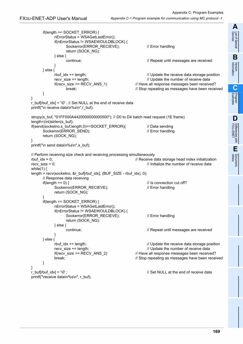
Appendix C: Program Examples
169
FX3U-ENET-ADP User's Manual
A
List of Special
Devices
B
Version
Information
C
Program
E
xamples
D
Differences w
ith F
X3U
-EN
ET
E
Docum
ent, others
Appendix C-1 Program example for communication using MC protocol -1
if(length == SOCKET_ERROR) {nErrorStatus = WSAGetLastError();if(nErrorStatus != WSAEWOULDBLOCK) {
Sockerror(ERROR_RECIEVE); // Error handlingreturn (SOCK_NG);
} else {continue; // Repeat until messages are received
}} else {
rbuf_idx += length; // Update the receive data storage positionrecv_size += length; // Update the number of receive dataif(recv_size >= RECV_ANS_1) // Have all response messages been received?
break; // Stop repeating as messages have been received}
}r_buf[rbuf_idx] = '\0' ; // Set NULL at the end of receive dataprintf("\n receive data\n%s\n",r_buf);
strcpy(s_buf, "01FF000A4420000000000500"); // D0 to D4 batch read request (1E frame)length=(int)strlen(s_buf);if(send(socketno,s_buf,length,0)==SOCKET_ERROR){ // Data sending
Sockerror(ERROR_SEND); // Error handlingreturn (SOCK_NG);
}printf("\n send data\n%s\n",s_buf);
// Perform receiving size check and receiving processing simultaneouslyrbuf_idx = 0; // Receive data storage head index initializationrecv_size = 0; // Initialize the number of receive datawhile(1) {length = recv(socketno, &r_buf[rbuf_idx], (BUF_SIZE - rbuf_idx), 0);
// Response data receivingif(length == 0) { // Is connection cut off?
Sockerror(ERROR_RECIEVE); // Error handlingreturn (SOCK_NG);
}if(length == SOCKET_ERROR) {
nErrorStatus = WSAGetLastError();if(nErrorStatus != WSAEWOULDBLOCK) {
Sockerror(ERROR_RECIEVE); // Error handlingreturn (SOCK_NG);
} else {continue; // Repeat until messages are received
}} else {
rbuf_idx += length; // Update the receive data storage positionrecv_size += length; // Update the number of receive dataif(recv_size >= RECV_ANS_2) // Have all response messages been received?break; // Stop repeating as messages have been received
}}r_buf[rbuf_idx] = '\0' ; // Set NULL at the end of receive dataprintf("\receive data\n%s\n", r_buf);
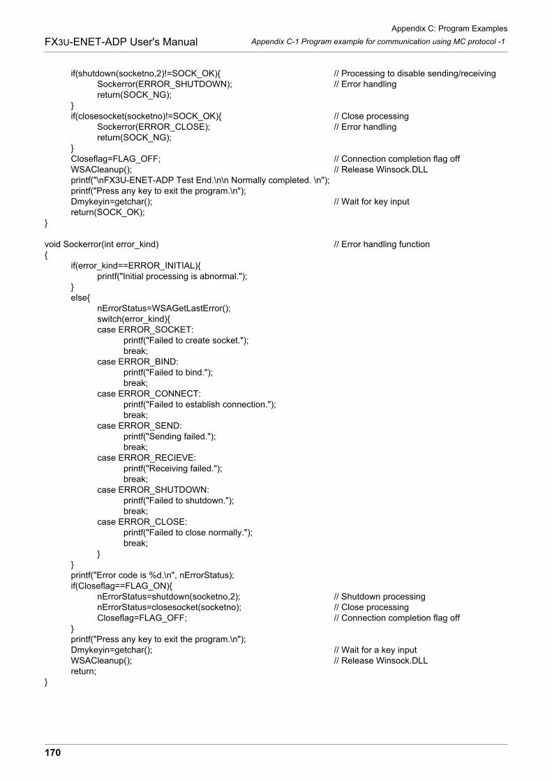
Appendix C: Program Examples
170
FX3U-ENET-ADP User's Manual Appendix C-1 Program example for communication using MC protocol -1
if(shutdown(socketno,2)!=SOCK_OK){ // Processing to disable sending/receivingSockerror(ERROR_SHUTDOWN); // Error handlingreturn(SOCK_NG);
}if(closesocket(socketno)!=SOCK_OK){ // Close processing
Sockerror(ERROR_CLOSE); // Error handlingreturn(SOCK_NG);
}Closeflag=FLAG_OFF; // Connection completion flag offWSACleanup(); // Release Winsock.DLLprintf("\nFX3U-ENET-ADP Test End.\n\n Normally completed. \n");printf("Press any key to exit the program.\n");Dmykeyin=getchar(); // Wait for key inputreturn(SOCK_OK);
}
void Sockerror(int error_kind) // Error handling function{
if(error_kind==ERROR_INITIAL){printf("Initial processing is abnormal.");
}else{
nErrorStatus=WSAGetLastError();switch(error_kind){case ERROR_SOCKET:
printf("Failed to create socket.");break;
case ERROR_BIND:printf("Failed to bind.");break;
case ERROR_CONNECT:printf("Failed to establish connection.");break;
case ERROR_SEND:printf("Sending failed.");break;
case ERROR_RECIEVE:printf("Receiving failed.");break;
case ERROR_SHUTDOWN:printf("Failed to shutdown.");break;
case ERROR_CLOSE:printf("Failed to close normally.");break;
}}printf("Error code is %d.\n", nErrorStatus);if(Closeflag==FLAG_ON){
nErrorStatus=shutdown(socketno,2); // Shutdown processingnErrorStatus=closesocket(socketno); // Close processingCloseflag=FLAG_OFF; // Connection completion flag off
}printf("Press any key to exit the program.\n");Dmykeyin=getchar(); // Wait for a key inputWSACleanup(); // Release Winsock.DLLreturn;
}
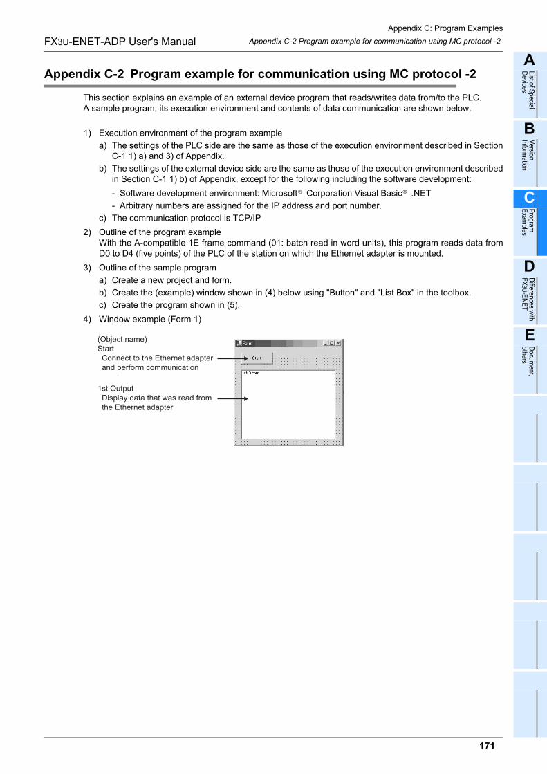
Appendix C: Program Examples
171
FX3U-ENET-ADP User's Manual
A
List of Special
Devices
B
Version
Information
C
Program
E
xamples
D
Differences w
ith F
X3U
-EN
ET
E
Docum
ent, others
Appendix C-2 Program example for communication using MC protocol -2
Appendix C-2 Program example for communication using MC protocol -2
This section explains an example of an external device program that reads/writes data from/to the PLC.A sample program, its execution environment and contents of data communication are shown below.
1) Execution environment of the program example
a) The settings of the PLC side are the same as those of the execution environment described in SectionC-1 1) a) and 3) of Appendix.
b) The settings of the external device side are the same as those of the execution environment describedin Section C-1 1) b) of Appendix, except for the following including the software development:
- Software development environment: Microsoft Corporation Visual Basic .NET
- Arbitrary numbers are assigned for the IP address and port number.
c) The communication protocol is TCP/IP
2) Outline of the program exampleWith the A-compatible 1E frame command (01: batch read in word units), this program reads data fromD0 to D4 (five points) of the PLC of the station on which the Ethernet adapter is mounted.
3) Outline of the sample program
a) Create a new project and form.
b) Create the (example) window shown in (4) below using "Button" and "List Box" in the toolbox.
c) Create the program shown in (5).
4) Window example (Form 1)
(Object name)Start Connect to the Ethernet adapter and perform communication
1st Output Display data that was read from the Ethernet adapter
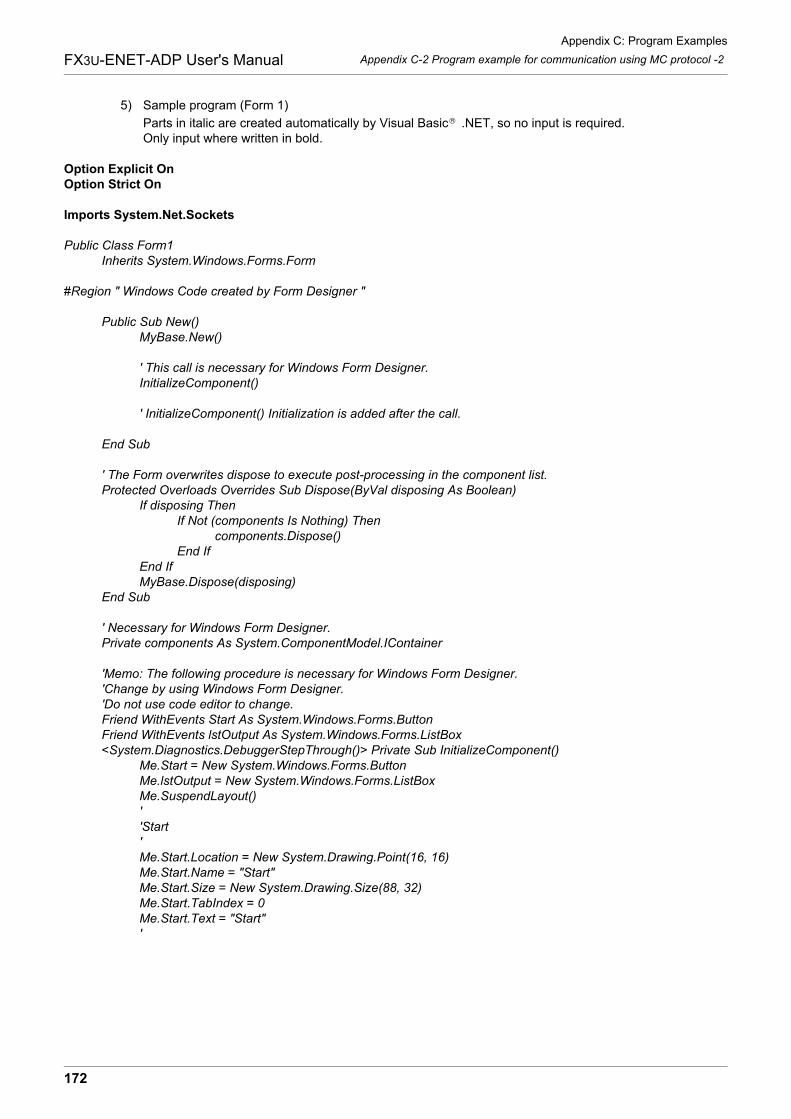
Appendix C: Program Examples
172
FX3U-ENET-ADP User's Manual Appendix C-2 Program example for communication using MC protocol -2
5) Sample program (Form 1)
Parts in italic are created automatically by Visual Basic .NET, so no input is required.Only input where written in bold.
Option Explicit OnOption Strict On
Imports System.Net.Sockets
Public Class Form1
Inherits System.Windows.Forms.Form
#Region " Windows Code created by Form Designer "
Public Sub New()
MyBase.New()
' This call is necessary for Windows Form Designer.
InitializeComponent()
' InitializeComponent() Initialization is added after the call.
End Sub
' The Form overwrites dispose to execute post-processing in the component list.
Protected Overloads Overrides Sub Dispose(ByVal disposing As Boolean)
If disposing Then
If Not (components Is Nothing) Then
components.Dispose()
End If
End If
MyBase.Dispose(disposing)
End Sub
' Necessary for Windows Form Designer.
Private components As System.ComponentModel.IContainer
'Memo: The following procedure is necessary for Windows Form Designer.
'Change by using Windows Form Designer.
'Do not use code editor to change.
Friend WithEvents Start As System.Windows.Forms.Button
Friend WithEvents lstOutput As System.Windows.Forms.ListBox
<System.Diagnostics.DebuggerStepThrough()> Private Sub InitializeComponent()
Me.Start = New System.Windows.Forms.Button
Me.lstOutput = New System.Windows.Forms.ListBox
Me.SuspendLayout()
'
'Start
'
Me.Start.Location = New System.Drawing.Point(16, 16)
Me.Start.Name = "Start"
Me.Start.Size = New System.Drawing.Size(88, 32)
Me.Start.TabIndex = 0
Me.Start.Text = "Start"
'
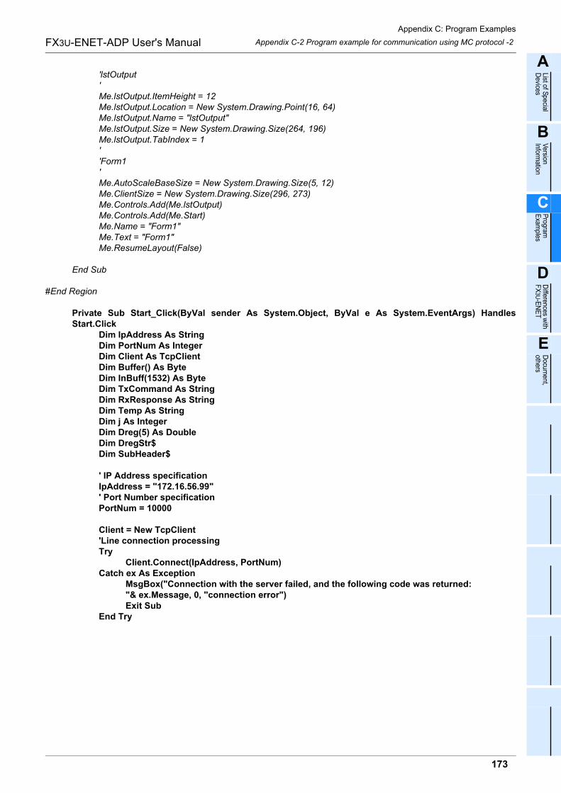
Appendix C: Program Examples
173
FX3U-ENET-ADP User's Manual
A
List of Special
Devices
B
Version
Information
C
Program
E
xamples
D
Differences w
ith F
X3U
-EN
ET
E
Docum
ent, others
Appendix C-2 Program example for communication using MC protocol -2
'lstOutput
'
Me.lstOutput.ItemHeight = 12
Me.lstOutput.Location = New System.Drawing.Point(16, 64)
Me.lstOutput.Name = "lstOutput"
Me.lstOutput.Size = New System.Drawing.Size(264, 196)
Me.lstOutput.TabIndex = 1
'
'Form1
'
Me.AutoScaleBaseSize = New System.Drawing.Size(5, 12)
Me.ClientSize = New System.Drawing.Size(296, 273)
Me.Controls.Add(Me.lstOutput)
Me.Controls.Add(Me.Start)
Me.Name = "Form1"
Me.Text = "Form1"
Me.ResumeLayout(False)
End Sub
#End Region
Private Sub Start_Click(ByVal sender As System.Object, ByVal e As System.EventArgs) HandlesStart.Click
Dim IpAddress As StringDim PortNum As IntegerDim Client As TcpClientDim Buffer() As ByteDim InBuff(1532) As ByteDim TxCommand As StringDim RxResponse As StringDim Temp As StringDim j As IntegerDim Dreg(5) As DoubleDim DregStr$Dim SubHeader$
' IP Address specificationIpAddress = "172.16.56.99"' Port Number specificationPortNum = 10000
Client = New TcpClient'Line connection processingTry
Client.Connect(IpAddress, PortNum)Catch ex As Exception
MsgBox("Connection with the server failed, and the following code was returned:"& ex.Message, 0, "connection error")Exit Sub
End Try
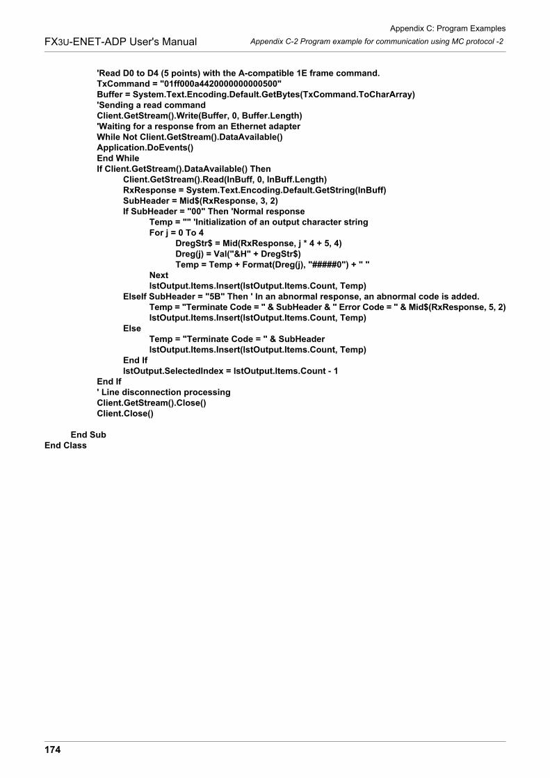
Appendix C: Program Examples
174
FX3U-ENET-ADP User's Manual Appendix C-2 Program example for communication using MC protocol -2
'Read D0 to D4 (5 points) with the A-compatible 1E frame command.TxCommand = "01ff000a4420000000000500"Buffer = System.Text.Encoding.Default.GetBytes(TxCommand.ToCharArray)'Sending a read commandClient.GetStream().Write(Buffer, 0, Buffer.Length)'Waiting for a response from an Ethernet adapterWhile Not Client.GetStream().DataAvailable()Application.DoEvents()End WhileIf Client.GetStream().DataAvailable() Then
Client.GetStream().Read(InBuff, 0, InBuff.Length)RxResponse = System.Text.Encoding.Default.GetString(InBuff)SubHeader = Mid$(RxResponse, 3, 2)If SubHeader = "00" Then 'Normal response
Temp = "" 'Initialization of an output character stringFor j = 0 To 4
DregStr$ = Mid(RxResponse, j * 4 + 5, 4)Dreg(j) = Val("&H" + DregStr$)Temp = Temp + Format(Dreg(j), "#####0") + " "
NextlstOutput.Items.Insert(lstOutput.Items.Count, Temp)
ElseIf SubHeader = "5B" Then ' In an abnormal response, an abnormal code is added.Temp = "Terminate Code = " & SubHeader & " Error Code = " & Mid$(RxResponse, 5, 2)lstOutput.Items.Insert(lstOutput.Items.Count, Temp)
ElseTemp = "Terminate Code = " & SubHeaderlstOutput.Items.Insert(lstOutput.Items.Count, Temp)
End IflstOutput.SelectedIndex = lstOutput.Items.Count - 1
End If' Line disconnection processingClient.GetStream().Close()Client.Close()
End SubEnd Class
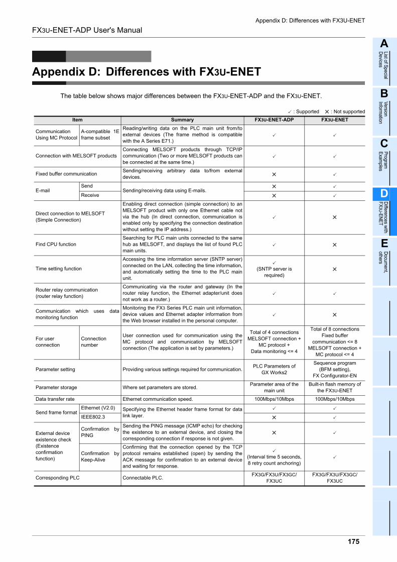
Appendix D: Differences with FX3U-ENET
175
FX3U-ENET-ADP User's Manual
A
List of Special
Devices
B
Version
Information
C
Program
E
xamples
D
Differences w
ith F
X3U
-EN
ET
E
Docum
ent, others
Appendix D: Differences with FX3U-ENET
The table below shows major differences between the FX3U-ENET-ADP and the FX3U-ENET.
: Supported : Not supported
Item Summary FX3U-ENET-ADP FX3U-ENET
Communication
Using MC Protocol
A-compatible 1E
frame subset
Reading/writing data on the PLC main unit from/to
external devices (The frame method is compatible
with the A Series E71.)
Connection with MELSOFT products
Connecting MELSOFT products through TCP/IP
communication (Two or more MELSOFT products can
be connected at the same time.)
Fixed buffer communicationSending/receiving arbitrary data to/from external
devices.
E-mailSend
Sending/receiving data using E-mails.Receive
Direct connection to MELSOFT
(Simple Connection)
Enabling direct connection (simple connection) to an
MELSOFT product with only one Ethernet cable not
via the hub (In direct connection, communication is
enabled only by specifying the connection destination
without setting the IP address.)
Find CPU function
Searching for PLC main units connected to the same
hub as MELSOFT, and displays the list of found PLC
main units.
Time setting function
Accessing the time information server (SNTP server)
connected on the LAN, collecting the time information,
and automatically setting the time to the PLC main
unit.
(SNTP server is
required)
Router relay communication
(router relay function)
Communicating via the router and gateway (In the
router relay function, the Ethernet adapter/unit does
not work as a router.)
Communication which uses data
monitoring function
Monitoring the FX3 Series PLC main unit information,
device values and Ethernet adapter information from
the Web browser installed in the personal computer.
For user
connection
Connection
number
User connection used for communication using the
MC protocol and communication by MELSOFT
connection (The application is set by parameters.)
Total of 4 connections
MELSOFT connection +
MC protocol +
Data monitoring <= 4
Total of 8 connections
Fixed buffer
communication <= 8
MELSOFT connection +
MC protocol <= 4
Parameter setting Providing various settings required for communication.PLC Parameters of
GX Works2
Sequence program
(BFM setting),
FX Configurator-EN
Parameter storage Where set parameters are stored.Parameter area of the
main unit
Built-in flash memory of
the FX3U-ENET
Data transfer rate Ethernet communication speed. 100Mbps/10Mbps 100Mbps/10Mbps
Send frame formatEthernet (V2.0) Specifying the Ethernet header frame format for data
link layer.IEEE802.3
External device
existence check
(Existence
confirmation
function)
Confirmation by
PING
Sending the PING message (ICMP echo) for checking
the existence to an external device, and closing the
corresponding connection if response is not given.
Confirmation by
Keep-Alive
Confirming that the connection opened by the TCP
protocol remains established (open) by sending the
ACK message for confirmation to an external device
and waiting for response.
(Interval time 5 seconds,
8 retry count anchoring)
Corresponding PLC Connectable PLC.FX3G/FX3U/FX3GC/
FX3UC
FX3G/FX3U/FX3GC/
FX3UC

Appendix D: Differences with FX3U-ENET
176
FX3U-ENET-ADP User's Manual
Connection system Connection method to the PLC.
Adapter connection
(Only the adapter final
stage (leftmost position)
connectable)
FX3U bus connection
Mounting position Mounting position when connected to the PLC.The left side of the main
unit
The right side of the main
unit
Number of I/O occupied pointsNumber of I/O points occupied when connected to the
PLC.0 point 8 point
Item Summary FX3U-ENET-ADP FX3U-ENET
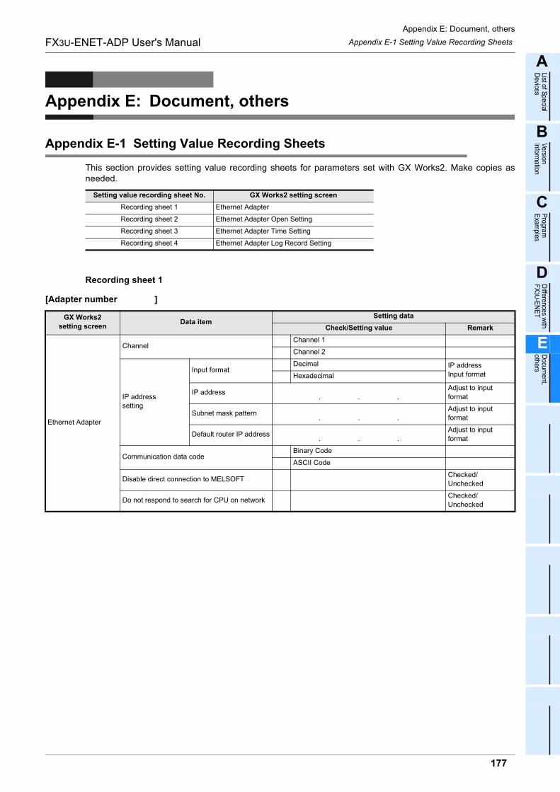
Appendix E: Document, others
Appendix E-1 Setting Value Recording Sheets
177
FX3U-ENET-ADP User's Manual
A
List of Special
Devices
B
Version
Information
C
Program
E
xamples
D
Differences w
ith F
X3U
-EN
ET
E
Docum
ent, others
Appendix E: Document, others
Appendix E-1 Setting Value Recording Sheets
This section provides setting value recording sheets for parameters set with GX Works2. Make copies asneeded.
Recording sheet 1
[Adapter number ]
Setting value recording sheet No. GX Works2 setting screen
Recording sheet 1 Ethernet Adapter
Recording sheet 2 Ethernet Adapter Open Setting
Recording sheet 3 Ethernet Adapter Time Setting
Recording sheet 4 Ethernet Adapter Log Record Setting
GX Works2
setting screenData item
Setting data
Check/Setting value Remark
Ethernet Adapter
ChannelChannel 1
Channel 2
IP address
setting
Input formatDecimal IP address
Input formatHexadecimal
IP address. . .
Adjust to input
format
Subnet mask pattern. . .
Adjust to input
format
Default router IP address. . .
Adjust to input
format
Communication data codeBinary Code
ASCII Code
Disable direct connection to MELSOFTChecked/
Unchecked
Do not respond to search for CPU on networkChecked/
Unchecked
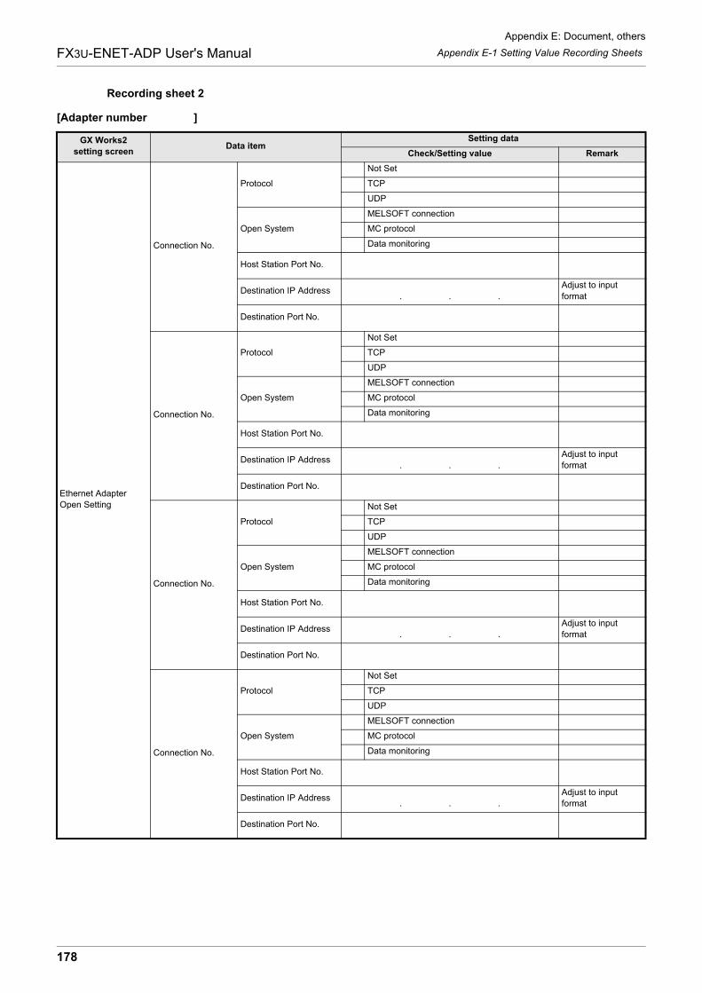
Appendix E: Document, others
Appendix E-1 Setting Value Recording Sheets
178
FX3U-ENET-ADP User's Manual
Recording sheet 2
[Adapter number ]
GX Works2
setting screenData item
Setting data
Check/Setting value Remark
Ethernet Adapter
Open Setting
Connection No.
Protocol
Not Set
TCP
UDP
Open System
MELSOFT connection
MC protocol
Data monitoring
Host Station Port No.
Destination IP Address. . .
Adjust to input
format
Destination Port No.
Connection No.
Protocol
Not Set
TCP
UDP
Open System
MELSOFT connection
MC protocol
Data monitoring
Host Station Port No.
Destination IP Address. . .
Adjust to input
format
Destination Port No.
Connection No.
Protocol
Not Set
TCP
UDP
Open System
MELSOFT connection
MC protocol
Data monitoring
Host Station Port No.
Destination IP Address. . .
Adjust to input
format
Destination Port No.
Connection No.
Protocol
Not Set
TCP
UDP
Open System
MELSOFT connection
MC protocol
Data monitoring
Host Station Port No.
Destination IP Address. . .
Adjust to input
format
Destination Port No.
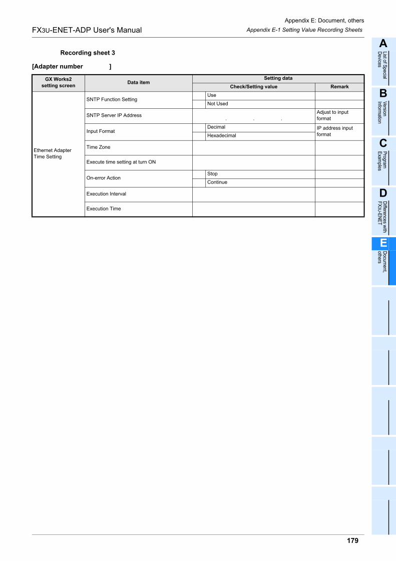
Appendix E: Document, others
Appendix E-1 Setting Value Recording Sheets
179
FX3U-ENET-ADP User's Manual
A
List of Special
Devices
B
Version
Information
C
Program
E
xamples
D
Differences w
ith F
X3U
-EN
ET
E
Docum
ent, others
Recording sheet 3
[Adapter number ]
GX Works2
setting screenData item
Setting data
Check/Setting value Remark
Ethernet Adapter
Time Setting
SNTP Function SettingUse
Not Used
SNTP Server IP Address. . .
Adjust to input
format
Input FormatDecimal IP address input
formatHexadecimal
Time Zone
Execute time setting at turn ON
On-error ActionStop
Continue
Execution Interval
Execution Time
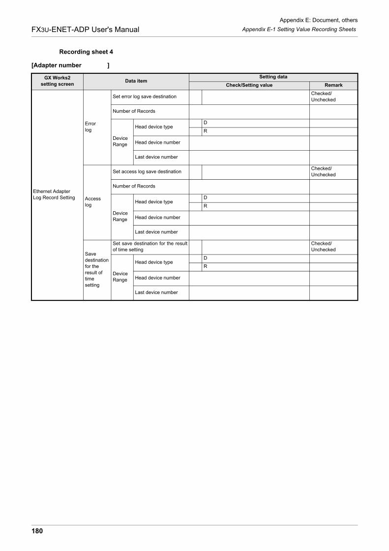
Appendix E: Document, others
Appendix E-1 Setting Value Recording Sheets
180
FX3U-ENET-ADP User's Manual
Recording sheet 4
[Adapter number ]
GX Works2
setting screenData item
Setting data
Check/Setting value Remark
Ethernet Adapter
Log Record Setting
Error
log
Set error log save destinationChecked/
Unchecked
Number of Records
Device
Range
Head device typeD
R
Head device number
Last device number
Access
log
Set access log save destinationChecked/
Unchecked
Number of Records
Device
Range
Head device typeD
R
Head device number
Last device number
Save
destination
for the
result of
time
setting
Set save destination for the result
of time setting
Checked/
Unchecked
Device
Range
Head device typeD
R
Head device number
Last device number
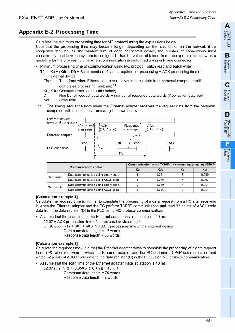
Appendix E: Document, others
Appendix E-2 Processing Time
181
FX3U-ENET-ADP User's Manual
A
List of Special
Devices
B
Version
Information
C
Program
E
xamples
D
Differences w
ith F
X3U
-EN
ET
E
Docum
ent, others
Appendix E-2 Processing Time
Calculate the minimum processing time for MC protocol using the expressions below.Note that the processing time may become longer depending on the load factor on the network (howcongested the line is), the window size of each connected device, the number of connections usedconcurrently, and how the system is configured. Use the values obtained from the expressions below as aguideline for the processing time when communication is performed using only one connection.
� Minimum processing time of communication using MC protocol (batch read and batch write)
Tfs = Ke + (Kdt Df) + Scr number of scans required for processing + ACK processing time of external device
Tfs : Time from when Ethernet adapter receives request data from personal computer until it
completes processing (unit: ms) *1
Ke, Kdt : Constant (refer to the table below)Df : Number of request data words + number of response data words (Application data part)Scr : Scan time
*1. The timing sequence from when the Ethernet adapter receives the request data from the personalcomputer until it completes processing is shown below.
[Calculation example 1]Calculate the required time (unit: ms) to complete the processing of a data request from a PC after receivingit, when the Ethernet adapter and the PC perform TCP/IP communication and read 32 points of ASCII codedata from the data register (D) in the PLC using MC protocol communication.
� Assume that the scan time of the Ethernet adapter installed station is 40 ms:
52.37 + ACK processing time of the external device (ms) 8 + (0.056 (12 + 66)) + 40 1 + ACK processing time of the external device
Command data length = 12 wordsResponse data length = 66 words
[Calculation example 2]Calculate the required time (unit: ms) the Ethernet adapter takes to complete the processing of a data requestfrom a PC after receiving it, when the Ethernet adapter and the PC performs TCP/IP communication andwrites 32 points of ASCII code data to the data register (D) in the PLC using MC protocol communication.
� Assume that the scan time of the Ethernet adapter installed station is 40 ms:
52.37 (ms) 8 + (0.056 (76 + 2)) + 40 1Command data length = 76 wordsResponse data length = 2 words
Communication contentCommunication using TCP/IP Communication using UDP/IP
Ke Kdt Ke Kdt
Batch readData communication using binary code 8 0.054 8 0.059
Data communication using ASCII code 8 0.056 7 0.067
Batch writeData communication using binary code 9 0.049 7 0.051
Data communication using ASCII code 8 0.056 8 0.051
ACK
END END
ACK(personal computer)External device
Ethernet adapter
PLC scan time
Command message
Step 0 Step 0
(TCP only)Response message (TCP only)
Tfs
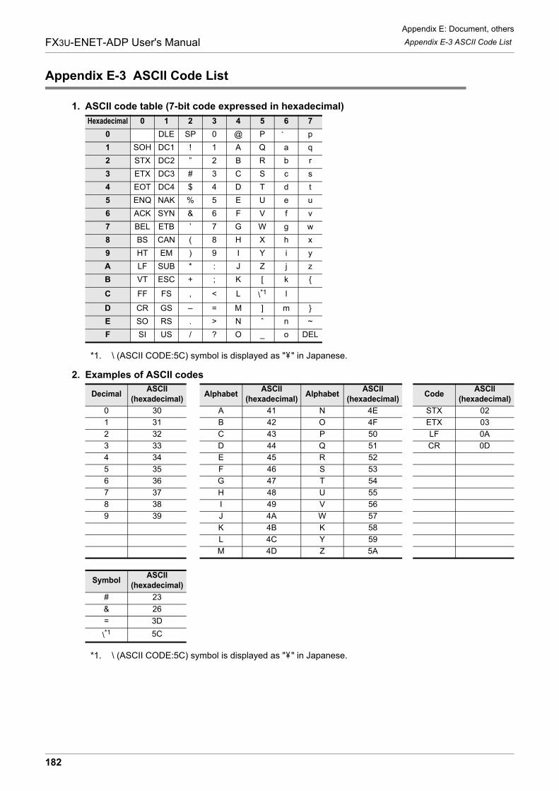
Appendix E: Document, others
Appendix E-3 ASCII Code List
182
FX3U-ENET-ADP User's Manual
Appendix E-3 ASCII Code List
1. ASCII code table (7-bit code expressed in hexadecimal)
*1. \ (ASCII CODE:5C) symbol is displayed as " " in Japanese.
2. Examples of ASCII codes
*1. \ (ASCII CODE:5C) symbol is displayed as " " in Japanese.
Hexadecimal 0 1 2 3 4 5 6 7
0 DLE SP 0 @ P ´ p
1 SOH DC1 ! 1 A Q a q
2 STX DC2 ” 2 B R b r
3 ETX DC3 # 3 C S c s
4 EOT DC4 $ 4 D T d t
5 ENQ NAK % 5 E U e u
6 ACK SYN & 6 F V f v
7 BEL ETB ’ 7 G W g w
8 BS CAN ( 8 H X h x
9 HT EM ) 9 I Y i y
A LF SUB * : J Z j z
B VT ESC + ; K [ k {
C FF FS , < L \*1 l
D CR GS – = M ] m }
E SO RS . > N ˆ n ~
F SI US / ? O _ o DEL
DecimalASCII
(hexadecimal)Alphabet
ASCII
(hexadecimal)Alphabet
ASCII
(hexadecimal)Code
ASCII
(hexadecimal)
0 30 A 41 N 4E STX 02
1 31 B 42 O 4F ETX 03
2 32 C 43 P 50 LF 0A
3 33 D 44 Q 51 CR 0D
4 34 E 45 R 52
5 35 F 46 S 53
6 36 G 47 T 54
7 37 H 48 U 55
8 38 I 49 V 56
9 39 J 4A W 57
K 4B K 58
L 4C Y 59
M 4D Z 5A
SymbolASCII
(hexadecimal)
# 23
& 26
= 3D
\*1 5C
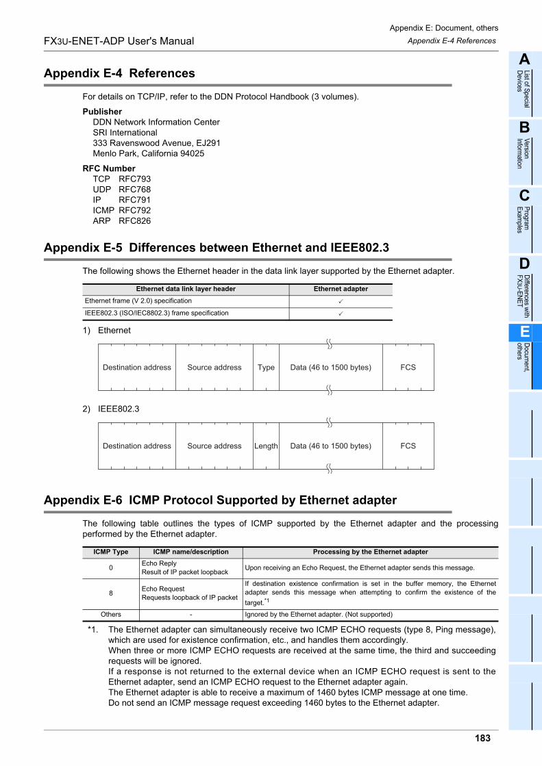
Appendix E: Document, others
Appendix E-4 References
183
FX3U-ENET-ADP User's Manual
A
List of Special
Devices
B
Version
Information
C
Program
E
xamples
D
Differences w
ith F
X3U
-EN
ET
E
Docum
ent, others
Appendix E-4 References
For details on TCP/IP, refer to the DDN Protocol Handbook (3 volumes).
PublisherDDN Network Information CenterSRI International333 Ravenswood Avenue, EJ291Menlo Park, California 94025
RFC NumberTCP RFC793UDP RFC768IP RFC791ICMP RFC792ARP RFC826
Appendix E-5 Differences between Ethernet and IEEE802.3
The following shows the Ethernet header in the data link layer supported by the Ethernet adapter.
1) Ethernet
2) IEEE802.3
Appendix E-6 ICMP Protocol Supported by Ethernet adapter
The following table outlines the types of ICMP supported by the Ethernet adapter and the processingperformed by the Ethernet adapter.
*1. The Ethernet adapter can simultaneously receive two ICMP ECHO requests (type 8, Ping message),which are used for existence confirmation, etc., and handles them accordingly. When three or more ICMP ECHO requests are received at the same time, the third and succeedingrequests will be ignored. If a response is not returned to the external device when an ICMP ECHO request is sent to theEthernet adapter, send an ICMP ECHO request to the Ethernet adapter again. The Ethernet adapter is able to receive a maximum of 1460 bytes ICMP message at one time. Do not send an ICMP message request exceeding 1460 bytes to the Ethernet adapter.
Ethernet data link layer header Ethernet adapter
Ethernet frame (V 2.0) specification
IEEE802.3 (ISO/IEC8802.3) frame specification
ICMP Type ICMP name/description Processing by the Ethernet adapter
0Echo Reply
Result of IP packet loopbackUpon receiving an Echo Request, the Ethernet adapter sends this message.
8Echo Request
Requests loopback of IP packet
If destination existence confirmation is set in the buffer memory, the Ethernet
adapter sends this message when attempting to confirm the existence of the
target.*1
Others - Ignored by the Ethernet adapter. (Not supported)
Destination address Source address Type Data (46 to 1500 bytes) FCS
Destination address Source address Length Data (46 to 1500 bytes) FCS

Appendix E: Document, others
Appendix E-6 ICMP Protocol Supported by Ethernet adapter
184
FX3U-ENET-ADP User's Manual
MEMO
185
FX3U-ENET-ADP User's Manual
Warranty
Warranty
Please confirm the following product warranty details before using this product.
1. Gratis Warranty Term and Gratis Warranty Range
[Gratis Warranty Term]
If any faults or defects (hereinafter "Failure") found to be
the responsibility of Mitsubishi occurs during use of the
product within the gratis warranty term, the product shall be
repaired at no cost via the sales representative or
Mitsubishi Service Company. However, if repairs are
required onsite at domestic or overseas location, expenses
to send an engineer will be solely at the customer's
discretion. Mitsubishi shall not be held responsible for any
re-commissioning, maintenance, or testing on-site that
involves replacement of the failed module. Overseas, repairs shall be accepted by Mitsubishi's local
overseas FA Center. Note that the repair conditions at
each FA Center may differ. The gratis warranty term of the product shall be for one
year after the date of purchase or delivery to a designated
place. Note that after manufacture and shipment from
Mitsubishi, the maximum distribution period shall be six (6)
months, and the longest gratis warranty term after
manufacturing shall be eighteen (18) months. The gratis
warranty term of repair parts shall not exceed the gratis
warranty term before repairs.
[Gratis Warranty Range]
The range shall be limited to normal use within the usage state, usage methods and usage environment, etc., which follow the conditions and precautions, etc., given in the instruction manual, user's manual and caution labels on the product.
1)
Even within the gratis warranty term, repairs shall be charged for in the following cases.
2)
Failure occurring from inappropriate storage or handling, carelessness or negligence by the user. Failure caused by the user's hardware or software design.
a)
Failure caused by unapproved modifications, etc., to the product by the user.
b)
Mitsubishi shall accept onerous product repairs for seven (7) years after production of the product is discontinued.Discontinuation of production shall be notified with Mitsubishi Technical Bulletins, etc.
1)
Product supply (including repair parts) is not available after production is discontinued.
2)
In using the Mitsubishi MELSEC programmable logic controller, the usage conditions shall be that the application will not lead to a major accident even if any problem or fault should occur in the programmable logic controller device, and that backup and fail-safe functions are systematically provided outside of the device for any problem or fault.
1)
The Mitsubishi programmable logic controller has been designed and manufactured for applications in general industries, etc. Thus, applications in which the public could be affected such as in nuclear power plants and other power plants operated by respective power companies, and applications in which a special quality assurance system is required, such as for Railway companies or Public service purposes shall be excluded from the programmable logic controller applications. In addition, applications in which human life or property that could be greatly affected, such as in aircraft, medical applications, incineration and fuel devices, manned transportation, equipment for recreation and amusement, and safety devices, shall also be excluded from the programmable logic controller range of applications. However, in certain cases, some applications may be possible, providing the user consults their local Mitsubishi representative outlining the special requirements of the project, and providing that all parties concerned agree to the special circumstances, solely at the users discretion.
2)
When the Mitsubishi product is assembled into a user's device, Failure that could have been avoided if functions or structures, judged as necessary in the legal safety measures the user's device is subject to or as necessary by industry standards, had been provided.
c)
Failure that could have been avoided if consumable parts (battery, backlight, fuse, etc.) designated in the instruction manual had been correctly serviced or replaced.
d)
Relay failure or output contact failure caused by usage beyond the specified Life of contact (cycles).
e)
Failure caused by external irresistible forces such as fires or abnormal voltages, and failure caused by force majeure such as earthquakes, lightning, wind and water damage.
f)
Failure caused by reasons unpredictable by scientific technology standards at time of shipment from Mitsubishi.
g)
Any other failure found not to be the responsibility of Mitsubishi or that admitted not to be so by the user.
h)
2. Onerous repair term after discontinuation of
production
4. Exclusion of loss in opportunity and secondary loss from warranty liability
3. Overseas service
The specifications given in the catalogs, manuals or
technical documents are subject to change without prior
notice.
5. Changes in product specifications
6. Product application
Regardless of the gratis warranty term, Mitsubishi shall not
be liable for compensation of damages caused by any
cause found not to be the responsibility of Mitsubishi, loss
in opportunity, lost profits incurred to the user or third
person by Failures of Mitsubishi products, special
damages and secondary damages whether foreseeable or
not, compensation for accidents, and compensation for
damages to products other than Mitsubishi products,
replacement by the user, maintenance of on-site
equipment, start-up test run and other tasks.

186
FX3U-ENET-ADP User's Manual
Revised History
Revised History
Date Revision Description
2/2012 A First Edition
5/2012 B � FX3G/FX3GC Series PLC was added.
� Supports the data monitoring function.
� Errors are corrected.
9/2012 C � Switch language function added.
� Errors are corrected.

HEAD OFFICE: TOKYO BUILDING, 2-7-3 MARUNOUCHI, CHIYODA-KU, TOKYO 100-8310, JAPANHIMEJI WORKS: 840, CHIYODA CHO, HIMEJI, JAPAN
JY997D45801C(MEE)
Effective Sep. 2012Specifications are subject to change without notice.
MODEL FX3UENETADP-U-E
MODEL CODE 09R725
FX3U-ENET-ADP
USER'S MANUAL