Embed Size (px)
Citation preview

Ericsson G32 / G36 Fixed Wireless Terminal for GSM/EDGE Mobile Networks
User Guide

EN/LZT 151 235 R1A © Ericsson AB 2006 — All Rights Reserved

Table of Contents
Fixed Wireless Terminal: G32 and G36 models 3
Table of Contents
Table of Contents.......................................... 3 Welcome....................................................... 4 Fixed Wireless Terminal ................................. 6 Installation..................................................... 9 Connecting Devices to the FWT .................. 16 Advanced Features ..................................... 24 PC Data Configurations............................... 34 Web-based Configuration............................ 53 Troubleshooting .......................................... 59 Technical Data ............................................ 63 Accessories ................................................ 66 Product Care and Safety ............................. 68 Warranty ..................................................... 72 Glossary...................................................... 74 Index........................................................... 76

Welcome
4 Fixed Wireless Terminal: G32 and G36 models
Welcome
Welcome to the User Guide for the G32 / G36 Fixed Wireless Terminal.
Important information: Some of the services described in this guide might not be supported by all networks. Please, contact your network operator for information on different network services operational in your GSM network.
The latest version of this user guide can be downloaded from:
http://www.ericsson.com/enterprise/library/manual.shtml
Disposal of the product
Your product should not be placed in municipal waste. Please check local regulations for disposal of electronic products.

Welcome
Fixed Wireless Terminal: G32 and G36 models 5
Copyright
No part of this document may be reproduced without the written permission of the copyright owner.
The contents of this document are subject to revision without notice due to continued progress in methodology, design and manufacturing. Ericsson shall have no liability for any error or damage of any kind resulting from the use of this document.
Warranty
ERICSSON MAKES NO WARRANTY OF ANY KIND WITH REGARD TO THIS MATERIAL, INCLUDING, BUT NOT LIMITED TO, THE IMPLIED WARRANTIES OF MERCHANTABILITY AND FITNESS FOR A PARTICULAR PURPOSE. Ericsson shall not be liable for errors contained herein nor for incidental or consequential damages in connection with the furnishing, performance or use of this material.
Declaration of Conformity
Hereby, Ericsson Enterprise AB declares that this product is in conformity with the requirements and other relevant provisions of the European R&TTE directive 1999/5/EC.
Details to be found at: http://ericsson.com/sdoc.
FCC Statement
Before a wireless terminal is available for sale to the public, it must be tested and certified to the FCC that it does not exceed the limit established by the government adopted requirement for safe exposure.
This device complies with CFR17 Part 15 and Part 24 of the FCC rules. Operation is subject to the following two conditions:
(1) This device may not cause harmful interference, and (2) this device must accept any interference received, including interference that may cause undesired operation.
Fixed Wireless Terminal
6 Fixed Wireless Terminal: G32 and G36 models
Fixed Wireless Terminal
Product Description
The FWT is a flexible and cost-effective solution for connection to the wireless GSM network when there is no fixed line infrastructure or if you need additional telephone lines.
The G36 can also be connected to a PBX so you can benefit from the Least Cost Routing (LCR) capabilities offered by most PBX vendors to optimize your costs by routing outgoing calls to mobile phones through the GSM network.
The FWT allows automatic network searching between GSM 850/1900 or GSM 900/1800 frequencies, ensuring world wide coverage in the GSM networks.
The FWT features the latest technology, which makes it perfect for everyday communication:
• Available in 2 dual dual-band GSM models (GSM 850/1900 or GSM 900/1800).
• Telephone line providing high quality speech, G3 fax and up to V.90 data transmission.
• EDGE (Enhanced Data Rates for GSM Evolution) is a 3G technology that delivers broadband-like speeds to GSM devices.
• GPRS (General Packet Radio Service), which keeps you always connected and facilitates rapid transmission of data (ideal for e-mail and Internet browsing).
• Embedded modem available over the USB port.
• Battery back-up (optional).
• PBX connectivity (only on the G36 model).

Fixed Wireless Terminal
Fixed Wireless Terminal: G32 and G36 models 7
Supplied Parts
After unpacking, please check that the following parts and list of components are included:
List of Components
1. FWT unit
2. Antenna
3. 4 x mounting screws
4. Power cable (USA, UK, EU or AUS)
5. AC/DC adapter
6. Wall mount bracket
7. Telephone cable
8. Quick Guide and User Guide manuals
9. CD with USB driver

Fixed Wireless Terminal
8 Fixed Wireless Terminal: G32 and G36 models
External Connector and Indicators

Installation
Fixed Wireless Terminal: G32 and G36 models 9
Installation
SIM Card
Your network operator provides you with a SIM (Subscriber Identity Module) card. The SIM card contains information about your telephone number and the services included in your subscription.
Preparing Your FWT
You need to follow these steps before you install the FWT on the wall and finalize all connections.
Warning: The FWT should be switched off before inserting or removing your SIM card or connecting any devices to the FWT.
Assembly
1. Connect the antenna.

Installation
10 Fixed Wireless Terminal: G32 and G36 models
2. Remove the front cover, by pressing down and pushing the small tab that is in the center of the bottom part of the FWT. Open the SIM Card holder and insert the SIM Card.
3. Close the SIM Card holder, placing it horizontally and securing it with the sliding part of the holder.
4. Install the battery (optional) in the battery compartment (over the SIM Card). To do so, connect the battery cable to the FWT connector. Connect the black cable to the negative pole (-) of the battery and the red cable to the positive pole (+). Fit the cable under the holding tab (over the SIM Card) and insert the battery until the tab fixates it.
5. Replace the front cover.
Connecting a telephone to the FWT
Connect an analog telephone to the line interface (RJ11) of the FWT.
Important: You may have to use this telephone to enter the PIN code.

Installation
Fixed Wireless Terminal: G32 and G36 models 11
Switch on the FWT
Connect the power supply. The FWT switches on automatically and the LED indicators start flashing.
Note: If the Power LED is off, there is a problem with the power supply. Please refer to the topic Troubleshooting documented on page 59for more detailed information.
Enter PIN
Most SIM cards are protected with a PIN (Personal Identity Number), which you get from your network operator and which you need in order to access the network. If the SIM card is not protected by a PIN code, then you do not need to enter a PIN.
The FWT starts the network search automatically. If the SIM card is protected by the PIN code, then the LEDs will flash simultaneously.
There are two ways of entering the PIN code:
• With the telephone
• Using the PC
Via telephone
Please follow these steps before you enter your PIN:
1. Pick up the telephone and dial the PIN code. Press the # key on your telephone or wait until you hear a beep tone.
2. If you make a mistake while entering your PIN, hang up the telephone and try again.
If the PIN is correct, you will hear a beep over the telephone (positive indication tone). If it is incorrect, a deep tone will sound (error indication tone).
Via web interface
Please follow these steps before you enter your PIN:
1. Connect your PC to the FWT.
• Via the USB Cable: insert the mini-USB plug into the corresponding connector on the FWT. Then insert the standard USB plug into any available USB port on your PC.
• Via an analog Modem: connect the analog modem to your PC as per modem supplier instructions. Then connect the telephone cable to your modem line output and RJ11 connector on the FWT.
2. Check that your computer has the standard modem installed, if not add one by following the steps described in PC Data Configurations on page 34.

Installation
12 Fixed Wireless Terminal: G32 and G36 models
3. Open your Web Browser on your PC, and type in the following URL: http://192.168.1.1/pin.asp
4. The following screen will be displayed.
5. Type in your PIN and then click on the Submit button.
If the PIN is entered incorrectly three times, the SIM card will be blocked. If this happens, you can unblock it by using the PUK (Personal Unblocking Key), which you also may get from your network operator. Please refer to the topic SIM Card Security documented on page 30 for more detailed information.
Note: Once you have entered the PIN code for the first time, you will not have to enter it again unless you change your SIM card. The FWT performs this operation automatically in case of power failure.
Network Search
After you have switched on your FWT and entered the PIN, the FWT automatically searches for a network.
When a network is found, the Radio LED is on or flashes depending on the GSM signal strength.
Note: If the Radio LED is off, you do not have access to the GSM network at your present location.
Now you have prepared the FWT for wall installation. Please, follow the instructions on the next page for complete wall installation.

Installation
Fixed Wireless Terminal: G32 and G36 models 13
Installing the FWT on the Wall
FWT Location
The GSM signal strength available at the FWT location affects the performance of the unit. The stronger the GSM signal, the better the FWT performance.
Tip: Test several potential locations by moving the FWT while looking at the Radio LED. Select the location where the Radio LED is continuous, or the location with the highest amount of flashes.
Note: Moving the FWT as little as 20 cm can affect the GSM reception quality.
Location Testing
Number of Radio LED flashes Location status
0 OFF Unacceptable
1 - - - Acceptable
2 - - - - - - Good
3 - - - - - - - - - Very Good
Continuously ………………… Excellent
Please consider the following recommendations:
• Always select an indoor indoor indoor indoor location, preferably close to a window and as high as possible in the building. Generally, you will experience better GSM signal strength in these places.
• Do not install the FWT in a wet or damp location.
• Do not install the FWT in an outdoor location.
• Do not install the FWT on walls or in rooms that contain large amounts of metal, steel or wiring.
• Do not expose the FWT to extreme temperatures (near radiators, cooling vents, etc).
If you experience poor reception quality, an outdoor antenna may improve reception. Please refer to the topic Accessories documented on page 66 for more detailed information.

Installation
14 Fixed Wireless Terminal: G32 and G36 models
Wall mounting
Please proceed as indicated in the following picture.
1. Fix the wall-mounting bracket on the wall.
2. Press the FWT against the wall-mounting bracket.
3. Slide the FWT downwards

Installation
Fixed Wireless Terminal: G32 and G36 models 15
Warning: Once you have fixed the FWT to the wall and switched it on, check the final status of the LEDs. If either one is off, then there is a problem with the power supply or the GSM signal.
Now the FWT is ready for connecting devices and making calls.
Note: If you want to remove the FWT from the wall bracket, then you have to press the tab (step 1) as indicated in the following picture and then slide the FWT upwards (step 2).

Connecting Devices to the FWT
16 Fixed Wireless Terminal: G32 and G36 models
Connecting Devices to the FWT
Warning: Before you start any connections please refer to the topic Product Care and Safety documented on page 68 for more detailed information and contact your network operator if you have any questions.
Warning: To ensure good protection against electrical discharges and the best audio quality, proper grounding of the power supply is strongly recommended.
Connecting devices to the FWT
Connect the devices to the FWT (RJ11 connector) in the same way as with an analog telephone line. The devices must be connected in parallel. You can connect the devices directly to the FWT telephone line connector (RJ11) or make an internal telephone wiring, use RJ11 splitters or similar connectors.
Connecting Devices to the FWT
Fixed Wireless Terminal: G32 and G36 models 17
The FWT is also equipped with a USB port that enables you to use it as a GSM modem. This enables PC fax and for data transfers as well as SMS services.
Note: When making the connections, the two-wire telephone cable polarity does not matter.
Tip: If your home or company is already wired with telephone cable, you only need to connect the cable to the FWT RJ11 connector and your telephone line will be up and running in all rooms.
Note: The telephone wire must be installed indoors.
Note: The telephone wire should not exceed 600 meters.
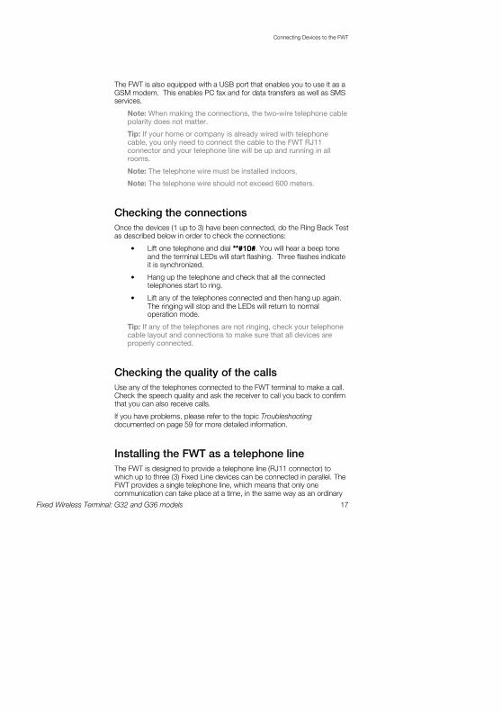
Checking the connections
Once the devices (1 up to 3) have been connected, do the Ring Back Test as described below in order to check the connections:
• Lift one telephone and dial **#10#**#10#**#10#**#10#. You will hear a beep tone and the terminal LEDs will start flashing. Three flashes indicate it is synchronized.
• Hang up the telephone and check that all the connected telephones start to ring.
• Lift any of the telephones connected and then hang up again. The ringing will stop and the LEDs will return to normal operation mode.
Tip: If any of the telephones are not ringing, check your telephone cable layout and connections to make sure that all devices are properly connected.
Checking the quality of the calls
Use any of the telephones connected to the FWT terminal to make a call. Check the speech quality and ask the receiver to call you back to confirm that you can also receive calls.
If you have problems, please refer to the topic Troubleshooting documented on page 59 for more detailed information.
Installing the FWT as a telephone line
The FWT is designed to provide a telephone line (RJ11 connector) to which up to three (3) Fixed Line devices can be connected in parallel. The FWT provides a single telephone line, which means that only one communication can take place at a time, in the same way as an ordinary

Connecting Devices to the FWT
18 Fixed Wireless Terminal: G32 and G36 models
fixed line. You cannot, for example, receive or originate a telephone call while sending or receiving a fax.
Warning: In order to avoid GSM interferences (noise), place the FWT at least three (3) meters (horizontal) away from electronic devices, including the telephone equipment connected to the FWT, or other household electronic devices such as televisions or radio receivers. The difference in height should be at least 2 meters (vertical). This is not necessary if you use telephone devices that fulfill the Immunity Characteristics settled by the IEC CISPR-24 standard. In this case, a minimum security distance of 20 cm is recommended.
Connecting the FWT to a PBX
This feature is only available for the FWT G36 model. The G36 FWT is designed to provide a telephone line (RJ11 connector) that behaves in the same way as an analog trunk.
Generic requirements
The PBX should meet the following generic requirements for G36 FWT connectivity:
• The PBX must provide analog trunks.
• One position of the trunk must be assigned to each G36 FWT.
• The trunk card must support either Busy Tone Detection (BTD) or Polarity Reversal Detection on answer and release.

Connecting Devices to the FWT
Fixed Wireless Terminal: G32 and G36 models 19
• The PBX can be programmed to utilize Least Cost Routing (LCR), if available, to automatically choose the trunk where the G36 FWT is connected.
• If the PBX does not offer LCR, choose the trunk where the G36 FWT is connected manually with a special dialed prefix. Check the installation in the same way as before.
The G36 FWT is compatible with most analog PBXs on the market.
G36 FWT connectivity to the analog trunk of the PBX
If the PBX fulfils the requirements for FWT connectivity, listed above, follow all the installation steps as described in the topic Installing the FWT on the Wall documented on page 13.
Note: A minimum distance of 3 meters between the G36 FWT and the PBX is recommended. The cable distance between the PBX and the G36 FWT should not exceed 600 meters, and the connection cable should be at least 0.4mm2 in diameter.
Warning: If you install more than one G36 FWT to a PBX, their antennas have to be separated by 20 cm in height or 2 meters in the horizontal.
If you are using an analog PBX — disconnect the telephone you have used to enter the PIN and test the FWT, and connect the analog trunk cable from the PBX to the FWT telephone line interface.
Check your PBX programming guide to see how to program your PBX to route certain calls through the FWT trunk if you are using a Least Cost Routing (LCR) programmed PBX. Once LCR is programmed, make a call to a mobile telephone number. See if the call is established through the FWT and check the speech quality.

Connecting Devices to the FWT
20 Fixed Wireless Terminal: G32 and G36 models
If the PBX does not offer the LCR option, choose the FWT trunk manually with a specific prefix. Check the installation in the same way as before. If you encounter problems, contact your distributor or network operator.
Warning: The PBX may require specific programming: both programming and installation should be done by specialized service personnel.
Using telephones
Telephones connected to the FWT work in the same way as if they were connected to a fixed line network.
Warning: You will not be able to make or receive data or fax calls while a speech call is ongoing.
Note: You can also benefit from some GSM functionality that you usually do not have in the fixed line network. Please refer to the topic Advanced Features documented on page 24 for more detailed information.
Please refer to the topic Audible Tones documented on page 62 for more detailed information.
Using fax machines
The FWT allows the connection of Group 3 analog fax machines to the telephone line interface, in the same way as a telephone.
Note: The fax communication service has to be registered with your network operator. Otherwise, the network will not allow faxes to be sent or received.
Note: You will not be able to make or receive other calls while a fax communication is established.
Sending a fax
The FWT is programmed to automatically detect outgoing calls made by an analog fax, meaning that the user simply has to use the fax in the same way as a conventional telephone line.
Warning: If your fax is an old model and is not able to send the fax identification, CNG tone, you should include *01* before the destination number (B-number) in order to inform the FWT that the next call is a fax call (Example: *01*B-number). This is not usually necessary, as most faxes automatically send the CNG tone so that the fax call is made automatically by the FWT.
Connecting Devices to the FWT
Fixed Wireless Terminal: G32 and G36 models 21
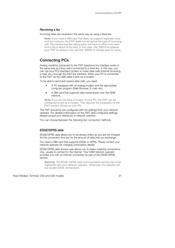
Receiving a fax
Incoming faxes are received in the same way as using a fixed line.
Note: If you have a SIM card that does not support separate voice and fax numbers, the FWT does not recognize the type of incoming call. This means that the calling party will have to inform you each time a fax is about to be sent. In this case, dial *9901# to prepare your FWT to receive a fax call Dial *9903# to change back to voice.
Connecting PCs
Analog modems connected to the FWT telephone line interface works in the same way as if they were connected to a fixed line. In this way, you can use your PCs standard modem to make data calls (Internet browsing, e-mail, etc.) through the FWT line interface. When your PC is connected to the FWT via the USB cable it acts as a modem
To be able to send and receive data calls, you need:
• A PC equipped with an analog modem and the appropriate computer program (Web Browser, E-mail, etc).
• A SIM card that supports data transmission over the GSM network.
Note: If you do not have a modem in your PC, the FWT can be configured to act as a modem. This requires the installation of the FWT modem drivers on your PC.
The FWT should be pre-configured with the settings from your network operator. For detailed information on the FWT data configured settings, please consult your distributor or network operator.
You can choose between the following two connection methods:
EDGE/GPRS data
EDGE/GPRS data allows you to be always online as you are not charged for the connection time but for the amount of data that you exchange.
You need a SIM card that supports EDGE or GPRS. Please contact your network operator for charging subscription details.
EDGE/GPRS data access type allows you to make outgoing connections only, usually to connect to the Internet. Your GSM network operator provides you with an Internet connection as part of the EDGE/GPRS service.
Warning: The EDGE /GPRS data communication service has to be registered with your network operator. Otherwise, the network will not accept EDGE connections.

Connecting Devices to the FWT
22 Fixed Wireless Terminal: G32 and G36 models
If your SIM card supports EDGE/GPRS, your network operator will supply you with a user name and password in order to access the EDGE/GPRS network if necessary, and optionally, to improve the Internet connection, a DNS address and a proxy address. All these settings will allow you to configure the Dial-up Networking program in your PC in order to establish an EDGE/GPRS connection.
Note: This procedure is similar to the way you configure an Internet connection from a specific ISP (Internet Service Provider).
If your network operator has provided you with an installation guide, please follow the instructions included in the guide.
Otherwise, the present manual explains the installation process. As the Dialup Networking is different for Windows™ NT/2000, Windows™ XP and Windows™ 2003 three separate descriptions are provided. Please refer to the topic PC Data Configurations documented on page 34 for more detailed information.
If you encounter problems during installation, please contact your distributor or network operator.
GSM data
GSM data is charged by time, this means you pay for the time you are connected. You need a SIM card that support GSM data.
The GSM data access type allows you to make both incoming and outgoing data calls, in the same way as with a fixed line. Therefore, you can connect to the Internet using the same ISP (Internet Service Provider) that you would use with a fixed line.
Note: You will not be able to make or receive other calls while a GSM data communication is established.
The SIM card must support GSM data. The network operator does not need to supply any specific information, and it is your ISP who provides you with the user name, password and installation information in order to establish an Internet connection. Please contact your ISP for installation instructions.
Note: Your PC should be configured in the same way as if using a fixed line, please check also that are you using the latest driver for the modem.
Tip: If you already have an Internet connection configured for a fixed line, you do not need to make any changes, just connect your PC to the FWT line (RJ11) instead of a fixed line.
Note: If your modem is an old model and it is not able to send the CNG tone, you should include *02* before the destination number (B-number) in order to indicate to the FWT that the call to be made is a data call (Example: *02*B-number). This is usually not

Connecting Devices to the FWT
Fixed Wireless Terminal: G32 and G36 models 23
necessary, as most modems automatically send the CNG tone so that the data call is made automatically by the FWT.
Incoming data calls are received in the same way as using a fixed line.
Note: If you have a SIM card that does not support separate voice and data numbers, the FWT does not recognize the type of incoming call. This means that the calling party will have to inform you each time a data call is about to be made. In this case, dial *9902# to prepare your FWT to receive a data call, Dial *9903# (to change back to voice).

Advanced Features
24 Fixed Wireless Terminal: G32 and G36 models
Advanced Features
If a DTMF telephone is connected to the FWT, the following features can be accessed.
Changing Volume
During a call, you can increase or decrease the reception volume level.
• Increase volume: dial R####
• Decrease volume: dial R****
Call Divert
You can divert incoming calls to another phone number when you are unable to answer.
The following table shows the divert alternatives as well as the way to proceed to manage this function.
Note: These dialing sequences may vary depending on your network operator. If these do not work, please consult your network operator or check the user guide provided with your subscription.
To manage
diversion of calls
…
With Function … Dial … You will hear…
Activate **21*Phone_number# 1 beep
Deactivate ##21# 3 beeps Always
Check status *#21# 1 beep if activated
3 beeps if deactivated
Activate **67*Phone_number# 1 beep
Deactivate ##67# 3 beeps When busy
Check status *#67# 1 beep if activated
3 beeps if deactivated

Advanced Features
Fixed Wireless Terminal: G32 and G36 models 25
To manage
diversion of calls
…
With Function … Dial … You will hear…
Activate **61*Phone_number# 1 beep
Deactivate ##61# 3 beeps When no answer
Check status *#61# 1 beep if activated
3 beeps if deactivated
Activate **62*Phone_number# 1 beep
Deactivate ##62# 3 beeps When out of reach
Check status *#62# 1 beep if activated
3 beeps if deactivated
All Deactivate ##002# 3 beeps
Note: If instead of hearing beeps you can hear a deep tone, this means that there has been an error in the activation or the deactivation.
Call Restriction / Call Barring
You can restrict certain types of calls that can be made or received. You need a password password password password to turn a call restriction on or off. Initially, this password will be 0000000000000000.
We recommend you to change it by dialing:
**03**OLD_PASSWORD*NEW_PASSWORD* NEW_PASSWORD#
The following table shows the restriction alternatives as well as the way to proceed to manage this function.
Note: These dialing sequences may vary depending on your network operator. If these do not work, please consult your network operator or check the user guide provided with your subscription.
To manage restriction of
calls … With Function … Dial … You will hear…
Activate *33*Password# 1 beep
Deactivate #33*Password# 3 beeps All outgoing calls
Check status *#33# 1 beep if activated
3 beeps if deactivated
Activate *331*Password# 1 beep
Deactivate #331*Password# 3 beeps All outgoing international
calls
Check status *#331# 1 beep if activated
3 beeps if deactivated
All outgoing international Activate *332*Password# 1 beep

Advanced Features
26 Fixed Wireless Terminal: G32 and G36 models
To manage restriction of
calls … With Function … Dial … You will hear…
Deactivate #332*Password# 3 beeps calls except your home
country
Check status *#332# 1 beep if activated
3 beeps if deactivated
Activate *35*Password# 1 beep
Deactivate #35*Password# 3 beeps All incoming calls
Check status *#35# 1 beep if activated
3 beeps if deactivated
Activate *351*Password# 1 beep
Deactivate #351*Password# 3 beeps All incoming calls when
you are abroad
Check status *#351# 1 beep if activated
3 beeps if deactivated
All Deactivate #330*Password# 3 beeps
Note: If instead of hearing beeps you hear a deep tone, this means that there has been an error in the activation or deactivation.
Multiparty Calls
You can handle more than one call simultaneously. For example, you can put an ongoing call on hold, while you make or answer a second call, and then switch between the two calls.
You can also set up a conference call to have a joint conversation with up to four people.
Call waiting service
If you wish to be able to receive a second call while another call is in progress, you must turn on the call waiting service.
Note: If you are engaged in a fax or a data call, any other incoming calls are rejected.
Note: These dialing sequences may vary depending on your network operator. If these do not work, please consult your network operator or check the user guide provided with your subscription.
To manage Call waiting Function… Dial… You will hear…
Activate *43# 1 beep
Deactivate #43# 3 beeps

Advanced Features
Fixed Wireless Terminal: G32 and G36 models 27
To manage Call waiting Function… Dial… You will hear…
Check status *#43# 1 beep if activated
3 beeps if deactivated
Note: If instead of hearing beeps you hear a deep tone, this means that there has been an error in the activation or deactivation.
Making a Second Call
You can only put one call on hold while you make a second call.
• To hold the active call: press the R R R R key on your telephone and proceed to make the second call.
• To switch between the two calls, press R2R2R2R2.
• To finish the active call and return to the held call, press R1R1R1R1.
Receiving a Second Call
If the call waiting service is on, you hear a tone in the telephone when you receive a second call.
• To ignore the waiting call, take no action.
• To continue with the ongoing call and reject the waiting call (give a User Busy indication tone to the waiting call): press R0. R0. R0. R0.
• To end the ongoing call and answer the waiting call: press R1. R1. R1. R1.
Note: If you hang up the telephone, you will also end the ongoing call and the telephone will ring again so that you can answer the waiting call as a normal call.
• To put the ongoing call on hold and answer the waiting call: press R2R2R2R2. You can switch again between both calls by pressing R2R2R2R2 each time.
Note: If “divert when busy” is on, the waiting call is diverted to the number you have specified.
Conference Calls
In a conference call, you can have a joint conversation with up to four other participants.
To create a conference call
• If you are in conversation with participant 1, put it on hold (press R), and dial participant 2.
Advanced Features
28 Fixed Wireless Terminal: G32 and G36 models
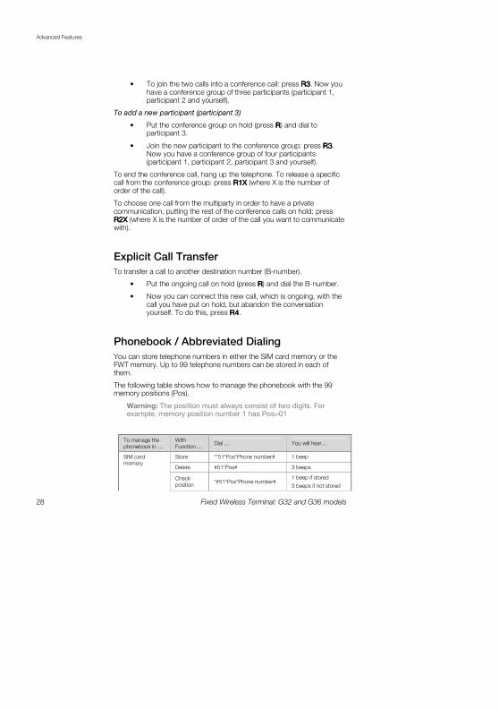
• To join the two calls into a conference call: press R3R3R3R3. Now you have a conference group of three participants (participant 1, participant 2 and yourself).
To add a new participant (participant 3)
• Put the conference group on hold (press RRRR) and dial to participant 3.
• Join the new participant to the conference group: press R3R3R3R3. Now you have a conference group of four participants (participant 1, participant 2, participant 3 and yourself).
To end the conference call, hang up the telephone. To release a specific call from the conference group: press R1X R1X R1X R1X (where X is the number of order of the call).
To choose one call from the multiparty in order to have a private communication, putting the rest of the conference calls on hold: press R2X R2X R2X R2X (where X is the number of order of the call you want to communicate with).
Explicit Call Transfer
To transfer a call to another destination number (B-number).
• Put the ongoing call on hold (press RRRR) and dial the B-number.
• Now you can connect this new call, which is ongoing, with the call you have put on hold, but abandon the conversation yourself. To do this, press R4R4R4R4.
Phonebook / Abbreviated Dialing
You can store telephone numbers in either the SIM card memory or the FWT memory. Up to 99 telephone numbers can be stored in each of them.
The following table shows how to manage the phonebook with the 99 memory positions (Pos).
Warning: The position must always consist of two digits. For example, memory position number 1 has Pos=01
To manage the
phonebook in …
With
Function … Dial … You will hear…
Store **51*Pos*Phone number# 1 beep
Delete #51*Pos# 3 beeps
SIM card
memory
Check
position *#51*Pos*Phone number#
1 beep if stored
3 beeps if not stored

Advanced Features
Fixed Wireless Terminal: G32 and G36 models 29
To manage the
phonebook in …
With
Function … Dial … You will hear…
Dial Pos# Dialing …
Store **51*Pos*Phone number*1# 1 beep
Delete #51*Pos*1# 3 beeps
Check position
*#51*Pos*Phone number*1# 1 beep if stored
3 beeps if not stored
Terminal memory
Dial Pos* Dialing …
Note: If instead of hearing beeps you hear a deep tone, this means that there has been an error in the activation or deactivation.
Voice Mail
The answering service of your network allows callers to leave a voice message when you cannot answer your calls. If you have voice mail, you will hear three (3) beeps before the dial tone, as soon as you pick up the receiver to make a call. Call your voice mail number in order to receive the voice mail message.
Note: This service may vary depending on your network operator. If these do not work, please consult your network operator or check the user guide provided with your subscription.
Sending Tone Signals
During a call, you can press keys 0-9, * and # to perform interactive services, for example banking by phone or control of an answering machine.
Minute Minder
If the minute minder is activated, you hear a beep once every minute during a call as a reminder of the duration of the ongoing call.
To manage minute minder function… Dial… You will hear…
Activate **42*1# 1 beep
Deactivate #42*1# 3 beeps
Check status *#42*1# 1 beep if activated 3 beeps if
deactivated
Note: If instead of hearing beeps you hear a deep tone, this means that there has been an error in the activation or deactivation.
Advanced Features
30 Fixed Wireless Terminal: G32 and G36 models
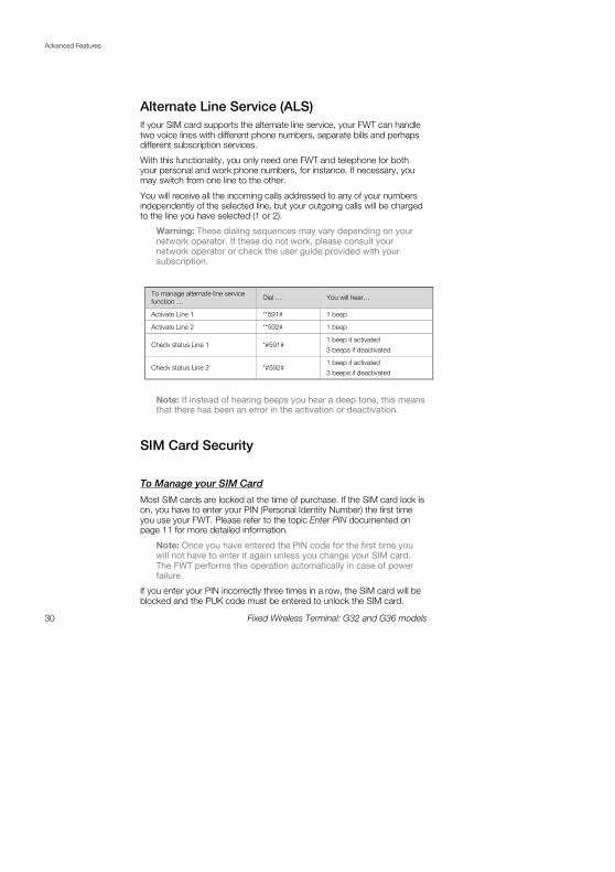
Alternate Line Service (ALS)
If your SIM card supports the alternate line service, your FWT can handle two voice lines with different phone numbers, separate bills and perhaps different subscription services.
With this functionality, you only need one FWT and telephone for both your personal and work phone numbers, for instance. If necessary, you may switch from one line to the other.
You will receive all the incoming calls addressed to any of your numbers independently of the selected line, but your outgoing calls will be charged to the line you have selected (1 or 2).
Warning: These dialing sequences may vary depending on your network operator. If these do not work, please consult your network operator or check the user guide provided with your subscription.
To manage alternate line service
function … Dial … You will hear…
Activate Line 1 **591# 1 beep
Activate Line 2 **592# 1 beep
Check status Line 1 *#591# 1 beep if activated
3 beeps if deactivated
Check status Line 2 *#592# 1 beep if activated
3 beeps if deactivated
Note: If instead of hearing beeps you hear a deep tone, this means that there has been an error in the activation or deactivation.
SIM Card Security
To Manage your SIM Card
Most SIM cards are locked at the time of purchase. If the SIM card lock is on, you have to enter your PIN (Personal Identity Number) the first time you use your FWT. Please refer to the topic Enter PIN documented on page 11 for more detailed information.
Note: Once you have entered the PIN code for the first time you will not have to enter it again unless you change your SIM card. The FWT performs this operation automatically in case of power failure.
If you enter your PIN incorrectly three times in a row, the SIM card will be blocked and the PUK code must be entered to unlock the SIM card.
Advanced Features
Fixed Wireless Terminal: G32 and G36 models 31
Please refer to the topic To Unblock your SIM Card documented on page 32 for more detailed information.
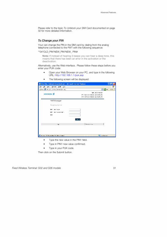
To Change your PIN
Your can change the PIN in the SIM card by dialing from the analog telephone connected to the FWT with the following sequence:
**04*OLD_PIN*NEW_PIN*NEW_ PIN#
Note: If instead of hearing 3 beeps you can hear a deep tone, this means that there has been an error in the activation or the deactivation.
Alternatively, use the Web interface. Please follow these steps before you enter your PUK code:
• Open your Web Browser on your PC, and type in the following URL: http://192.168.1.1/puk.asp
• The following screen will be displayed:
• Type the new value in the PIN1 field.
• Type in PIN1 new value confirmed.
• Type in your PUK code.
Then click on the Submit button.

Advanced Features
32 Fixed Wireless Terminal: G32 and G36 models
To Unblock your SIM Card
To unblock your SIM card, you need to enter your PUK (Personal Unblocking Key), which can be supplied by your network operator.
The procedure to enter the PUK is exactly the same as for entering the PIN.
Note: If you enter the wrong PUK ten times in a row, your card will be permanently blocked. If this happens, you should contact your network operator.
In order to unblock your SIM card and change the PIN at the same time, please dial the following sequence:
**05*PUK*NEW_PIN*NEW_ PIN#
Note: If instead of hearing 3 beeps you can hear a deep tone, this means that there has been an error in the activation or the deactivation.
Alternatively, use the Web interface. Please follow these steps before you enter your PUK code:
• Open your Web Browser on your PC, and type in the following URL: http://192.168.1.1/puk.asp
• The following screen will be displayed:
• Type the new value in the PIN1 field.
• Type in PIN1 new value confirmed.
• Type in your PUK code.
• Then click on the Submit button.

Advanced Features
Fixed Wireless Terminal: G32 and G36 models 33
PC Data Configurations
34 Fixed Wireless Terminal: G32 and G36 models
PC Data Configurations
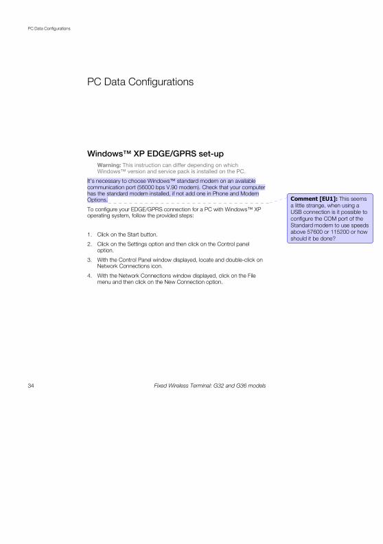
Windows™ XP EDGE/GPRS set-up
Warning: This instruction can differ depending on which Windows™ version and service pack is installed on the PC.
It’s necessary to choose Windows™ standard modem on an available communication port (56000 bps V.90 modem). Check that your computer has the standard modem installed, if not add one in Phone and Modem Options.
To configure your EDGE/GPRS connection for a PC with Windows™ XP operating system, follow the provided steps:
1. Click on the Start button.
2. Click on the Settings option and then click on the Control panel option.
3. With the Control Panel window displayed, locate and double-click on Network Connections icon.
4. With the Network Connections window displayed, click on the File menu and then click on the New Connection option.
Comment [EU1]: This seems a little strange, when using a USB connection is it possible to
configure the COM port of the Standard modem to use speeds above 57600 or 115200 or how
should it be done?

PC Data Configurations
Fixed Wireless Terminal: G32 and G36 models 35
5. With the Welcome to the New Connection Wizard screen displayed, click on the Next button.
6. With the Network Connection Type screen displayed, select the Connect to the Connect to the Connect to the Connect to the IIIInternetnternetnternetnternet option and click on the Next button

PC Data Configurations
36 Fixed Wireless Terminal: G32 and G36 models
7. With the Getting Ready screen displayed, select the Set up my Set up my Set up my Set up my connection manuallyconnection manuallyconnection manuallyconnection manually option and click on the Next button.
8. With the Internet Connection screen displayed, select the Connect Connect Connect Connect using a dialusing a dialusing a dialusing a dial----up modemup modemup modemup modem option and click on the Next button.

PC Data Configurations
Fixed Wireless Terminal: G32 and G36 models 37
9. With the Connection Name screen displayed, type the ISP Name you require in the ISP Name field and click on the Next button.
10. With the Phone Number to Dial screen displayed, type the phone number you will use during the dial up process in the Phone number field. Click on the Next button.
Note: To Access the web-based configuration pages enter the phone number *98*06#.

PC Data Configurations
38 Fixed Wireless Terminal: G32 and G36 models
11. With the Connection Availability screen displayed, select the Anyone’s use Anyone’s use Anyone’s use Anyone’s use option and click on the Next button.
12. If your operator requires certain Internet Account information when you do a dial up, you have to complete all the relevant information on the displayed Internet Account Information screen. Once you have completed all the required information, click on the Next button.

PC Data Configurations
Fixed Wireless Terminal: G32 and G36 models 39
13. With the Completing the New Connection Wizard screen displayed, ensure that you select the Add a shortcut to this connection to my Add a shortcut to this connection to my Add a shortcut to this connection to my Add a shortcut to this connection to my desktop desktop desktop desktop check box option. Click on the Finish button.
You have now successfully configured a new dial up connection using the Windows™ New Connection Wizard.
14. Locate and double-click on the newly created EDGE/GPRS connection icon

PC Data Configurations
40 Fixed Wireless Terminal: G32 and G36 models
15. With the Connect screen displayed, confirm all the displayed information and click on the Dial button.
Note: To Access the web-based configuration pages enter the phone number *98*06#.

PC Data Configurations
Fixed Wireless Terminal: G32 and G36 models 41
Windows™ NT/2000 EDGE/GPRS set-up
Note: Your PC must have the Remote Access Service and the TCP/IP protocol installed within the network components. You can check this in ‘Start->Settings->Control Panel’ and double clicking on ‘Network’. If not, these components have to be previously added from your Windows™ installation disk.
To configure your EDGE/GPRS connection for a PC with Windows™ NT/2000 as operating system, follow the provided steps:
1. Locate and double-click on the My Computer icon located on your desktop.
2. Locate and double-click on the Network and Dial-Up Connections icon.
3. With the Dial Up Networking screen displayed, double-click on the Make New ConnectionMake New ConnectionMake New ConnectionMake New Connection option.
4. With the Location Information screen displayed:
• Select the country or region that you are situated in from the What country/region are you in now?What country/region are you in now?What country/region are you in now?What country/region are you in now? option.
• Specify the area or city code as well as the number you need to dial when you access an outside line, if it is required.
• Select whether your phone system uses Tone or Pulse dialing.

PC Data Configurations
42 Fixed Wireless Terminal: G32 and G36 models
5. Click on the OK button.
6. Phone and Modem Options select ‘OK’ to proceed
7. Network Connection Wizard. Click ‘Next’.
PC Data Configurations
Fixed Wireless Terminal: G32 and G36 models 43
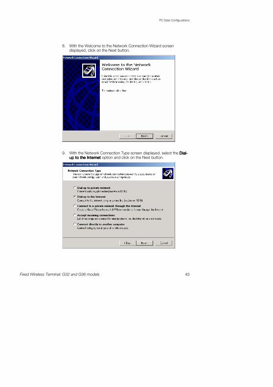
8. With the Welcome to the Network Connection Wizard screen displayed, click on the Next button.
9. With the Network Connection Type screen displayed, select the DialDialDialDial----up to the up to the up to the up to the IIIInternetnternetnternetnternet option and click on the Next button.
PC Data Configurations
44 Fixed Wireless Terminal: G32 and G36 models
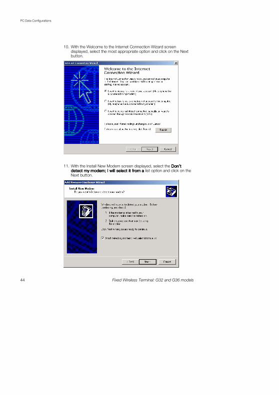
10. With the Welcome to the Internet Connection Wizard screen displayed, select the most appropriate option and click on the Next button.
11. With the Install New Modem screen displayed, select the Don’t Don’t Don’t Don’t detect my modem; I will select it from a detect my modem; I will select it from a detect my modem; I will select it from a detect my modem; I will select it from a list option and click on the Next button.

PC Data Configurations
Fixed Wireless Terminal: G32 and G36 models 45
12. With the Install New Modem screen displayed, select the appropriate modem from the displayed options and click on the Next button.
13. With the Install New Modem screen displayed, select the most appropriate communication port from the displayed list. Click on the Next button.
PC Data Configurations
46 Fixed Wireless Terminal: G32 and G36 models
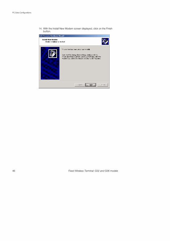
14. With the Install New Modem screen displayed, click on the Finish button.
PC Data Configurations
Fixed Wireless Terminal: G32 and G36 models 47
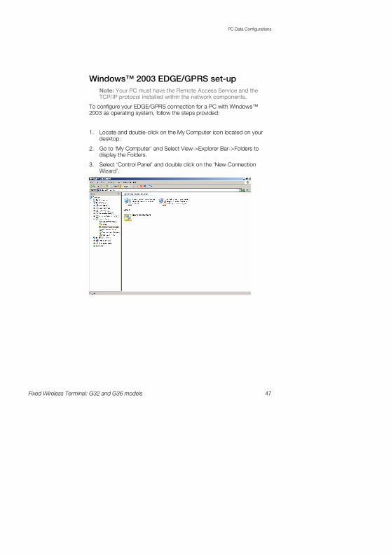
Windows™ 2003 EDGE/GPRS set-up
Note: Your PC must have the Remote Access Service and the TCP/IP protocol installed within the network components.
To configure your EDGE/GPRS connection for a PC with Windows™ 2003 as operating system, follow the steps provided:
1. Locate and double-click on the My Computer icon located on your desktop.
2. Go to ‘My Computer’ and Select View->Explorer Bar->Folders to display the Folders.
3. Select ‘Control Panel’ and double click on the ‘New Connection Wizard’.

PC Data Configurations
48 Fixed Wireless Terminal: G32 and G36 models
4. With the Welcome to the New Connection Wizard screen displayed, click on the Next button.
5. With the Network Connection Type screen displayed, select the Connect to the InternetConnect to the InternetConnect to the InternetConnect to the Internet option and click on the Next button.

PC Data Configurations
Fixed Wireless Terminal: G32 and G36 models 49
6. With the Internet Connection screen displayed, select the Connect Connect Connect Connect using a dialusing a dialusing a dialusing a dial----up modemup modemup modemup modem option and click on the Next button.
7. With the Connection Name screen displayed, type the name of your ISP (Internet Service Provider), and click on the Next button.

PC Data Configurations
50 Fixed Wireless Terminal: G32 and G36 models
8. With the Phone Number to Dial screen displayed, type your ISP’s phone number and click on the Next button.
Note: To Access the web-based configuration pages enter the phone number *98*06#.
9. With the Connection Availability screen displayed, select the Anyone’s Anyone’s Anyone’s Anyone’s use option and click on the Next button.

PC Data Configurations
Fixed Wireless Terminal: G32 and G36 models 51
10. If your operator requires certain Internet Account information when you do a dial up, you have to complete all the relevant information on the displayed Internet Account Information screen. Once you have completed all the required information, click on the Next button.
11. With the Completing the New Connection Wizard screen displayed, ensure that you select the Add a shortcut to this connection to my Add a shortcut to this connection to my Add a shortcut to this connection to my Add a shortcut to this connection to my desktop desktop desktop desktop check box option. Click on the Finish button.

PC Data Configurations
52 Fixed Wireless Terminal: G32 and G36 models
You have now successfully configured a new dial up connection using the Windows™ New Connection Wizard.
12. Locate and double-click on the newly created EDGE/GPRS connection icon
13. With the Connect screen displayed, confirm all the displayed information and click on the Dial button.
Note: To Access the web-based configuration pages enter the phone number *98*06#.

Web-based Configuration
Fixed Wireless Terminal: G32 and G36 models 53
Web-based Configuration
This chapter describes the interface and user settings (volume, ringing signals, dial speed setups etc) that are available and the procedures for the use of your PCs standard modem to make data calls (Internet browsing, e-mail, etc.) through the FWT line interface. To be able to send and receive data calls, you need:
• A PC equipped with an analog modem and the appropriate computer program (Web Browser, E-mail, etc).
• A SIM card that supports data transmission over the GSM network.
Note: If you do not have a modem in your PC, the FWT can be configured to act as a modem. Please refer to the topic Connecting PCs documented on page 21 for more detailed information.
To be able to access the User Interface settings the following steps must be followed:
• Open your Web Browser on your PC, and type the following default URL: http://192.168.1.1/default.asp
• The following configuration page will be displayed.
Note: Use PDP context 6 to access the web-based configuration pages on the FWT, e.g. *98*06#.

Web-based Configuration
54 Fixed Wireless Terminal: G32 and G36 models
Localization
Allows you to change the language in which the web page will be displayed. The options are:
• English (default)
• Spanish
User settings
This option will allow you to change the reception volume level from 0 to 3, the default is 1.
Ringing Signals
Ring Signal functionality
Activation of the ring signal functionality according the following conditions:
• Disabled for all incoming calls
• Enabled for all incoming calls
Comment [BK2]: The
screenshots don’t look very sharp?? The same goes for all
screenshots in this section
Web-based Configuration
Fixed Wireless Terminal: G32 and G36 models 55
• Enabled only for voice calls
• Enabled only for fax calls
• Enabled only for data calls
• Enabled only for fax and data calls
As default “Enabled, all incoming calls” is selected
Ringing signal sequence
This provides the possibility of setting different ringing sequences depending on the incoming call’s nature. By default the four possibilities are set to be the same as when receiving a regular voice call. The four different ringing types are defined on the line parameters setting stored in the FWT during the manufacturing stage.
Ringing signal defined
Ringing signal used for regular incoming voice call.
Line 2 ringing signal defined sequence
Ringing signal used for ALS (Alternate Line Service) activated and calls to line 2.
Fax ringing signal defined sequence
Ringing signal used for incoming fax call.
Data ringing signal defined sequence
Ringing signal used for incoming data call.

Web-based Configuration
56 Fixed Wireless Terminal: G32 and G36 models
Calling Line Identification Presentation
Selection of Calling Line Identification Presentation (CLIP) functions. Allowed protocols are:
• ETSI V.23
• ETSI DTMF
• Bellcore
• None
By default, this functionality is set to the ETSI V.23 protocol.
Abbreviated Dialing
This check box option allows a user to Enable/Disable the abbreviated dialing function.
By default, this functionality is set to Enabled.
Comment [EU3]: Hans: Bad
quality on the picture.
Web-based Configuration
Fixed Wireless Terminal: G32 and G36 models 57
Dial Speed Setup
This setting allows you to adjust the dialing speed (interval between digits). There are five possibilities. By default, this functionality is set to Normal.
Minute minder
Indicates if the minute minder is active or not. By default, this functionality is set to Deactivated.
Call Setup
Define the bearer capability by default for all calls if no indication is done. Allowed parameters are:
• Speech
• Fax
• Circuit switched data
This is a useful function when dedicated voice-only, fax-only or data-only lines are simulated with the FWT.
By default, this functionality is set to Speech.
Pre-defined B-number/bearer capabilities
These settings define five specific B-numbers (Destination numbers) along with a predetermined bearer capability. This feature is useful for those applications in which fax and data calls have to be sent to a specific destination and the terminal equipment does not send the correspondent Fax CNG or Data CNG tone.
Each number is defined with the following two settings:
• Destination number —the number that has a bearer capability associated. Up to 20 character-numbers can be programmed.
• Bearer capability- the bearer capability associated to a destination number. This bearer capability can be voice, fax or circuit-switched data.
Web-based Configuration
58 Fixed Wireless Terminal: G32 and G36 models
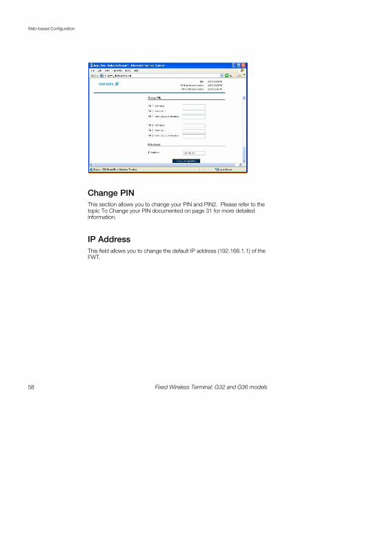
Change PIN
This section allows you to change your PIN and PIN2. Please refer to the topic To Change your PIN documented on page 31 for more detailed information.
IP Address
This field allows you to change the default IP address (192.168.1.1) of the FWT.

Troubleshooting
Fixed Wireless Terminal: G32 and G36 models 59
Troubleshooting
This chapter describes the procedures to identify and, if possible, correct problems that might occur with the FWT or its installation. Some problems require that you call your network operator, but most problems you may encounter can be easily corrected.
LED indicators
The FWT has two LED indicators: The Radio LED (green) indicates the network signal strength, according to the following table:
Color Number of flashes Network signal strength
OFF 0 Unacceptable (no networks)
Green 1 - - - - Acceptable
Green 2 -- -- -- Good
Green 3 --- --- --- Very good
Green Continuous --------- Excellent
Troubleshooting
60 Fixed Wireless Terminal: G32 and G36 models
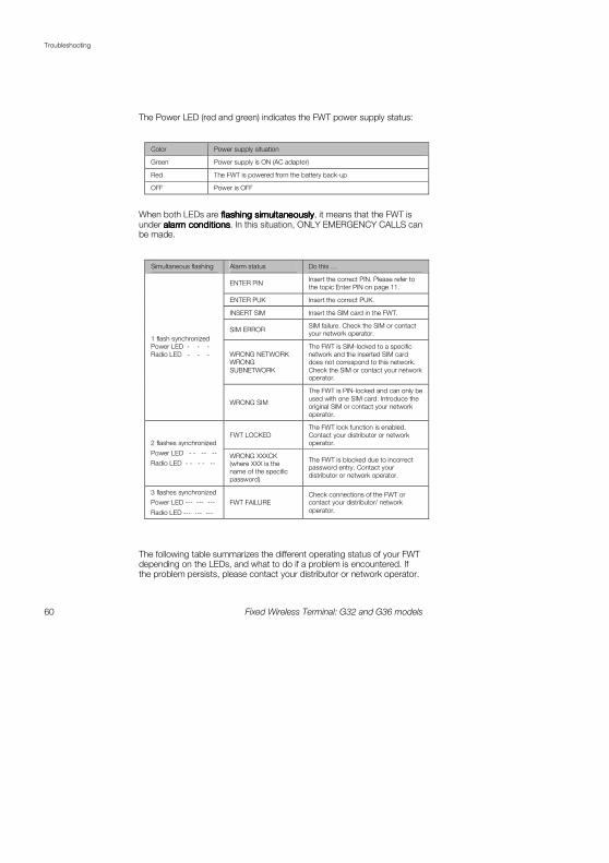
The Power LED (red and green) indicates the FWT power supply status:
Color Power supply situation
Green Power supply is ON (AC adapter)
Red The FWT is powered from the battery back-up
OFF Power is OFF
When both LEDs are flashing simultaneouslyflashing simultaneouslyflashing simultaneouslyflashing simultaneously, it means that the FWT is under alarm conditionsalarm conditionsalarm conditionsalarm conditions. In this situation, ONLY EMERGENCY CALLS can be made.
Simultaneous flashing Alarm status Do this …
ENTER PIN Insert the correct PIN. Please refer to
the topic Enter PIN on page 11.
ENTER PUK Insert the correct PUK.
INSERT SIM Insert the SIM card in the FWT.
SIM ERROR SIM failure. Check the SIM or contact your network operator.
WRONG NETWORK
WRONG
SUBNETWORK
The FWT is SIM-locked to a specific
network and the inserted SIM card
does not correspond to this network.
Check the SIM or contact your network operator.
1 flash synchronized
Power LED - - -
Radio LED - - -
WRONG SIM
The FWT is PIN-locked and can only be
used with one SIM card. Introduce the
original SIM or contact your network
operator.
FWT LOCKED
The FWT lock function is enabled.
Contact your distributor or network
operator. 2 flashes synchronized
Power LED - - -- --
Radio LED - - - - -- WRONG XXXCK (where XXX is the
name of the specific
password)
The FWT is blocked due to incorrect password entry. Contact your
distributor or network operator.
3 flashes synchronized
Power LED --- --- ---
Radio LED --- --- ---
FWT FAILURE
Check connections of the FWT or contact your distributor/ network
operator.
The following table summarizes the different operating status of your FWT depending on the LEDs, and what to do if a problem is encountered. If the problem persists, please contact your distributor or network operator.

Troubleshooting
Fixed Wireless Terminal: G32 and G36 models 61
LED indicators status
If you see… It means… Do this…
Power LED Green
Radio LED ON or
flashing
� AC power is ON.
� The FWT is connected
to the cellular network
and available for use.
� Normal operation mode
� Start using your FWT.
� If Radio LED is flashing, refer to
the topic FWT Location on
page 13.
� If you are unable to make a
call, check the telephone cable connection or the PBX
connections and program.
Both LEDs OFF � AC Power is OFF
� Verify that the AC power plug is securely connected to the
AC power outlet.
� Check that the DC power cord
is connected to the FWT.
� Check the circuit breaker or fuse for the AC electrical circuit
that supplies power to the AC
outlet that the FWT is
connected too.
Power LED Green
Radio LED OFF
� AC Power is ON
� The FWT is not connected to the cellular
network. The FWT is not
available for use.
� Verify that the antenna is properly installed.
� Verify you have installed the
FWT in the best location and
that the antenna is properly
connected. Refer to the topic
FWT Location on page 13.
Power LED Red
Radio LED Green
or flashing
� AC power is OFF. The
FWT is operating using the battery back-up
power
� The FWT is connected to the cellular network
and available for use.
� Verify that the AC power cords
are securely connected to the AC power outlet.
� Check that the power cable is
connected to the FWT.
� Check the circuit breaker or
fuse for the AC electrical circuit
that supplies power to the AC
input of the FWT power supply.
Power LED Red
Radio LED OFF
� AC power is OFF. The
FWT is operating using
battery back-up power.
� The FWT is not connected to the cellular
network. The FWT is not
ready for use.
� Verify that the AC power cord
is securely connected to the
AC power outlet.
� Check that the power cable is
connected to the FWT.
� Check the circuit breaker or
fuse for the AC electrical circuit
that supplies power to the AC
outlet that the FWT is
connected to.
Both LEDs Flashing
(simultaneously)
� Alarm status
� The FWT is blocked or it has an internal fault
� Check the alarm status table
above.
� Contact your distributor or network operator for
assistance.
Troubleshooting
62 Fixed Wireless Terminal: G32 and G36 models
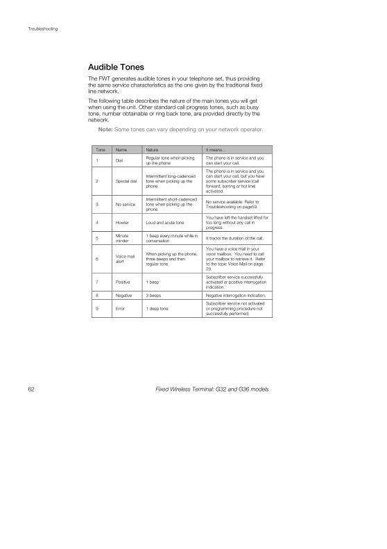
Audible Tones
The FWT generates audible tones in your telephone set, thus providing the same service characteristics as the one given by the traditional fixed line network.
The following table describes the nature of the main tones you will get when using the unit. Other standard call progress tones, such as busy tone, number obtainable or ring back tone, are provided directly by the network.
Note: Some tones can vary depending on your network operator.
Tone Name Nature It means...
1 Dial Regular tone when picking
up the phone
The phone is in service and you
can start your call.
2 Special dial
Intermittent long-cadenced
tone when picking up the
phone
The phone is in service and you can start your call, but you have
some subscriber service (call
forward, barring or hot line)
activated.
3 No service
Intermittent short-cadenced
tone when picking up the
phone
No service available. Refer to Troubleshooting on page59.
4 Howler Loud and acute tone
You have left the handset lifted for too long without any call in
progress.
5 Minute
minder
1 beep every minute while in
conversation It tracks the duration of the call.
6 Voice mail
alert
When picking up the phone,
three beeps and then
regular tone
You have a voice mail in your
voice mailbox. You need to call
your mailbox to retrieve it. Refer
to the topic Voice Mail on page
29.
7 Positive 1 beep
Subscriber service successfully
activated or positive interrogation
indication.
8 Negative 3 beeps Negative interrogation indication.
9 Error 1 deep tone
Subscriber service not activated
or programming procedure not
successfully performed.

Technical Data
Fixed Wireless Terminal: G32 and G36 models 63
Technical Data
GSM Air Interface
Frequency Bands: GSM 850/1900 or GSM 900/1800.
GSM 850
Frequencies: TX 824-849 MHz, RX 869-915MHz
RF power: Maximum 2 W (30 dBm)
Power class 4
GSM 900
Frequencies: TX 880-915 MHz, RX 925-960 MHz
RF power: Maximum 2 W (33 dBm)
Power class 4
GSM 1800
Frequencies: TX 1710-1785 MHz, RX 1805-1880 MHz
RF power: Maximum 1 W (30 dBm)
Power class 1
GSM 1900
Frequencies: TX 1850-1910 MHz, RX 1930-1990 MHz.
RF power: Maximum 1 W (30 dBm)
Power class 1
Data capabilities: Multi-slot EDGE/GPRS Class 10 (data rates depend on network operator)
Speech codec: Full Rate, Enhanced Full Rate, Half Rate and Adaptive Multi-Rate (AMR)

Technical Data
64 Fixed Wireless Terminal: G32 and G36 models
FWT Interfaces
Basic Kit
The Basic Kit consists of: FWT unit, power supply, mains cable, wall-mount bracket, antenna, Quick Installation Guide and User Guide manuals and telephone cable.
• Size: Height 148 mm, Width 165 mm
• Depth: 45 mm
• Weight: 310 grams
• SIM card: Small plug-in card, 1.8V or 3V type
Telephone Interfaces
• Telephones: RJ11 (a/b 2-wire line); telephone interface
• Analog Fax: Group 3 Fax transmission
• Analog Data: V.90, V.34, V.32bis, V.32, V.22bis, V.22, V.23, V.21, Bell 212A & 103
• CLI: ETSI DTMF and V.23; Bellcore FSK
• Line Impedance: 600 ohm (default)
• Loop Current: 25 mA (off-hook)
• Open loop voltage: 48 V (on-hook)
• Loop resistance: < 650 ohm (off-hook)
• Ringing voltage: 45 Vrms
• Ring Load: 3 REN; up to 3 telephone devices
• Call Control signaling; polarity reversal and loop-break (G36 only)
USB Interface
• USB 1.1 (mini-B female)
• Data services: all applicable GSM 7.07 AT commands
• SMS: all applicable GSM 7.05 AT commands
GSM Antenna
• SMA plug-female (50 ohm)

Technical Data
Fixed Wireless Terminal: G32 and G36 models 65
• Frequency Bands: GSM 850/1900 or GSM 900/1800
• Dual band antennas depending on model types: e.g. model types FWT G32a (American) cover the frequencies of 850/1900 MHz and model types FWT G32e (European) cover the frequencies of 900/1800 MHz
• Characteristics: omni-directional
Power Supply
• Power Input VDC: 7.5 VDC; 0.8 A (class 4, male)
• AC Input: 100 - 240 VAC; 47 - 63 Hz 3 pole AC inlet connector (IEC 320 power inlet)
• Available plugs: EU, UK, USA, and AU
Environmental Conditions
• Operating Temperature: -10ºC to +55ºC
• Operating Humidity: 20 — 75 %
• Storage Temperature: -40ºC to +85ºC
• Storage Humidity: 5 - 95%

Accessories
66 Fixed Wireless Terminal: G32 and G36 models
Accessories
The G3x series FWT benefits from a wide range of accessories, which ensure the best and easiest way to install, serve and maintain the FWT, enhancing their functionality. Only these, approved-by-Ericsson, accessories will guarantee the quality and performance of the FWT.
Antennas
In areas where coverage is poor, the following accessory antenna can be used to enhance the FWT performance:
External dual band omni directional antenna
External dual band omni directional antenna is used for installation or in places where indoor coverage is unstable.
Band: dual 900/1800 MHz. Gain: 3dBi. Cable: 3m Connector: SMA male.
Band: dual 850/1900 MHz. Gain: 3dBi. Cable: 3m Connector: SMA male.
Outdoor directional antenna
The directional antenna is intended to be wall or pole mounted by means of a bracket. The antenna has the highest gain amongst the FWT antennas. Band: 850/900/1800/1900 MHz. Gains: 10dBi. Cable: 7.5 m. Connector: SMA male.
Battery
The FWT can be installed with a backup battery:
• Rechargeable lead-acid battery: 6V, 1.2-1.3 Ah with 2.5 hours continuous conversation, 13.5 hours stand-by.

Accessories
Fixed Wireless Terminal: G32 and G36 models 67
Warning: Ericsson recommends precaution when handling lead-acid batteries, and also special attention over storage and power loss issues. Please refer to the topic Product Care and Safety documented on page 68 for more detailed information.
Battery Cable
The battery cable is used to connect the backup battery to the FWT.
DC/DC Power Converter
This accessory can be used to connect a DC voltage power system (car battery, solar cell, etc.) to feed the FWT. DC Input: 10-32 VDC.
USB Cable
The USB cable can be used to connect the FWT to a PC, in which case the FWT acts as a modem for data transmission. This allows you to use the FWT for SMS, fax and data services. To send/receive SMS or faxes via the Terminal a 3rd party application is required.
USB to RS232 Adapter
For PCs that do not have a USB port this USB-to-RS232 adaptor converts a standard serial port to a USB port. This can be used in conjunction with the USB cable to connect a PC and the FWT.
Mechanical Antitheft Lock
The mechanical lock serves as an anti-theft device. It fits into the wall mounting bracket; the FWT is then installed onto the wall mounting bracket as normal. The mechanical lock prevents removal of the FWT from the wall mounting bracket. The FWT can be removed by using the Mechanical Key
Mechanical Antitheft Key
The mechanical key is used to “unlock” the FWT in cases of the mechanical lock being used. The key is inserted into the “keyhole” at the bottom of the FWT between the unit and the wall mounting bracket. It releases the FWT unit from the wall mounting bracket

Product Care and Safety
68 Fixed Wireless Terminal: G32 and G36 models
Product Care and Safety
Note: Please read this information before using your FWT.
Save this User Guide since it contains important safety information and operating instructions.
Product care
• Treat your product with care. Keep it in a clean and dust-free place.
• Do not expose your FWT to liquid or moisture or humidity.
• Do not expose your FWT to extreme high or low temperatures; refer to the topic Technical Data documented on page 63 for more detailed information.
• Do not expose your FWT to open flames or lit tobacco products.
• Do not use the FWT in an area where a potentially explosive atmosphere exists.
• Do not attempt to disassemble your FWT. A broken warranty seal will void the warranty. The product does not contain consumer serviceable components. Only Certified Service Centers should perform service.
• Do not use any accessories other than those approved by Ericsson. Use of non-Ericsson original, or non-Ericsson approved accessories, may result in loss of performance, damage to the product, fire, electric shock or injury and may violate regulations. The warranty does not cover product failures that have been caused by use of non-Ericsson original, or non-Ericsson approved accessories.

Product Care and Safety
Fixed Wireless Terminal: G32 and G36 models 69
Antenna care
• Use only an antenna that has been specifically designed and approved for your FWT. Use of unauthorized antennas, modifications, or attachments could damage the FWT and may violate the appropriate regulations, causing loss of performance and radio frequency (RF) energy above the recommended limits.
• Do not hold or touch the antenna when the FWT is in use. Holding or touching the antenna affects call quality.
• Do not use the FWT if the antenna or antenna cable is damaged or missing.
• Do not place the telephone cord or the power supply cord on or near the FWT antenna or antenna cable.
• Do not cover or place an obstruction on or around the antenna.
Radio wave exposure information
This fixed wireless access terminal is a low-power radio transmitter and receiver. During use, it emits low levels of radio frequency energy (also known as radio waves or radio frequency fields).
Governments around the world have adopted comprehensive international safety guidelines, developed by scientific organizations, e.g. ICNIRP (International Commission on Non-Ionizing Radiation Protection) and IEEE (The Institute of Electrical and Electronics Engineers Inc.) through periodic and thorough evaluation of scientific studies. These guidelines establish permitted levels of radio wave exposure for the general population. The levels include a safety margin designed to assure the safety of all persons, regardless of age and health, and to account for any variations in measurements.
Specific Absorption Rate (SAR) is the unit of measurement for the amount of radio frequency energy absorbed by the body. The SAR level for this product was determined at the highest certified power level in laboratory conditions using a measurement standard published by the European Committee for Electrotechnical Standardization (CENELEC).
With the antenna solutions recommended by Ericsson, the maximum radio wave exposure is below the limit in the international safety guidelines within a few centimeters from the antenna. Consequently, for recommended placement of the terminal and antenna, the radio wave exposure levels are below the limits.
More information on radio frequency exposure can be found on:
www.ericsson.com/health.

Product Care and Safety
70 Fixed Wireless Terminal: G32 and G36 models
Personal medical devices
Radio waves may affect the operation of cardiac pacemakers and other implanted equipment. If a minimum distance of 15 cm is kept between the antenna and the pacemaker, the risk of interference is limited. If you have any reason to suspect that interference is taking place, immediately move away from the antenna. Contact your cardiologist for more information.
For other medical devices, please consult the manufacturer of the device.
Potentially explosive atmospheres
Do not use your product in an area where a potentially explosive atmosphere exists.
Power supply
• Ensure that your AC power outlet is adequately grounded, that it is situated near the FWT and it is easily accessible.
• Connect the power supply cord only to the AC power outlet that meets the specifications marked on the FWT power supply.
• Never alter the AC power cord or plug. If necessary have the correct outlet installed by a qualified electrician or call your service provider for assistance.
• To reduce risk of damage to the electric cord, remove it from the outlet by holding onto the AC adapter rather than the cord.
• Make sure the cord is positioned so that it will not be stepped on, tripped over or otherwise subjected to damage or stress.
Children
DO NOT ALLOW CHILDREN TO PLAY WITH YOUR FWT SINCE IT CONTAINS SMALL PARTS THAT COULD BECOME DETACHED AND CREATE A CHOKING HAZARD.
Battery information
Warning: When a battery is not installed or is connected to a terminal that is switched off, it should be recharged during 24 hours every 6 months.
Product Care and Safety
Fixed Wireless Terminal: G32 and G36 models 71
• Do not expose the battery to extreme temperatures, never above +60°C. For maximum battery capacity, use the battery in room temperature.
• Do not let the metal contacts on the battery touch another metal object. This could short-circuit and damage the battery.
• Do not expose the battery to open flames. This could cause the battery to explode.
• Do not expose the battery to liquid.
• Do not allow the battery to be put into the mouth. Battery electrolytes may be toxic if swallowed.
• Do not puncture or burn the battery. The battery contains corrosive liquids and materials.
• If the battery leaks and the liquid inside spills on the skin or clothing immediately wash it off with plenty of clean water. If the liquid splashes into eyes, immediately flush the eyes with plenty of clean water and consult a doctor.
Moving or Storing the FWT
Turn off the FWT by disconnecting the power supply as well as the battery (if one is installed).
If you are transporting the FWT on an aircraft, you will be asked to remove the battery from the unit. For updated information about the transportation and use of wireless communication equipment, contact the appropriate local and national regulatory agency or your service provider.
Accessing the battery compartment
This label appears under the battery compartment indicating that the terminal should always be switchedswitchedswitchedswitched off off off off before attempting to access the battery compartment.

Warranty
72 Fixed Wireless Terminal: G32 and G36 models
Warranty
Limited Warranty
Thank you for purchasing this Ericsson Product. To get the maximum use out of your new product, we recommend that you follow a few simple steps:
• Read the Guidelines for safe and efficient use.
• Read all of the terms and conditions of the Ericsson Warranty listed below.
• Save your original receipt, this is necessary for warranty repair claims. Should your Ericsson Product need warranty service, you should return it to the dealer from whom it was purchased or contact your local Ericsson helpdesk for further information.
Ericsson Warranty
Ericsson warrants this Product to be free from defects in material and workmanship at the time of its original purchase by a customer, and for a subsequent period of one (1) year.
All accessories for the Product are covered by a warranty period of one (1) year from the date of original purchase by a customer.
What Ericsson will do
If, during the warranty period, this Product fails to operate under normal use and service, due to improper materials or workmanship, Ericsson subsidiaries, authorized distributors, or authorized service partners will replace the Product in accordance with the terms and conditions stipulated herein.
For efficiency purposes, Customers are reminded that should their Ericsson Product need warranty service, they return it to the dealer from
Warranty
Fixed Wireless Terminal: G32 and G36 models 73
which it was purchased or call their local Ericsson helpdesk for further information on warranty claims.
Conditions
1. The warranty given herein is only valid if the original receipt issued by the dealer to the original purchaser, specifying the date of purchase and serial number, is presented along with the Product to be replaced. Warranty service may be refused if this information is not available or has been removed or changed after the original purchaser of the Product from the dealer.
2. Any replaced Product will be warranted for the remainder of the original warranty period. Replacement may be via functionally equivalent reconditioned units. Replaced faulty parts or components will become the property of Ericsson.
3. This warranty does not cover any failure of the Product due to normal wear and tear, misuse, including but not limited to use in other than a normal and customary manner, in accordance with Ericsson’s instructions for use and maintenance of the Product, accident, modification or adjustment, acts of God, improper ventilation, or damage resulting from liquid.
4. This warranty does not cover product failures due to repair installations, modifications or improper service performed by a non-Ericsson authorized service workshop, opening of the Product by a non-Ericsson authorized person or use of non-Ericsson original accessories.
5. Batteries are not covered by this warranty.
6. Tampering with any of the seals on the Product will void this warranty.
7. THERE ARE NO OTHER EXPRESS WARRANTIES, WHETHER WRITTEN OR ORAL, OTHER THAN THIS PRINTED LIMITED WARRANTY. ALL IMPLIED WARRANTIES, INCLUDING WITHOUT LIMITATION IMPLIED WARRANTIES OF MERCHANTABILITY OR FITNESS FOR A PARTICULAR PURPOSE, ARE LIMITED TO THE DURATION OF THIS LIMITED WARRANTY. IN NO EVENT WILL ERICSSON BE LIABLE FOR LOSS OF PROFITS, COMMERCIAL LOSS, INCIDENTAL OR CONSEQUENTIAL DAMAGES OF ANY NATURE; TO THE FULL EXTENT THOSE DAMAGES CAN BE DISCLAIMED BY LAW.
Some countries do not allow for the exclusion or limitation of loss of profits, commercial loss, incidental or consequential damages, or limitation of the duration of implied warranties, so the preceding limitations or exclusions may not be applicable in certain cases. This warranty gives specific legal rights, and depending on the country, other rights may be available as well.
Glossary
74 Fixed Wireless Terminal: G32 and G36 models
Glossary
The following definitions are supplied in order to better understand certain concepts included in this manual:
BBBB----numbernumbernumbernumber
The B-number refers to the number that you dial. It is also commonly referred to as destination number, called number, called party number.
EDGEEDGEEDGEEDGE
Enhanced Data rates for GSM Evolution is a 3G technology that delivers broadband-like data speeds to mobile devices. It allows consumers to connect to the Internet and send and receive data, including images, web pages and photographs, three times faster than possible with an ordinary GSM/GPRS network.
Fixed Line DevicesFixed Line DevicesFixed Line DevicesFixed Line Devices
Any analog devices that can be connected to the analog fixed line:
• Fixed Telephones- ordinary telephones for a fixed line.
• G3 Faxes- ordinary fax machines available on the market.
• CLI devices- ordinary displays or telephones equipped with displays that show the caller number for incoming calls.
• V.90 modems- standard modems for PCs used to make data connections over the ordinary fixed line.
FWT (Fixed Wireless Terminal)FWT (Fixed Wireless Terminal)FWT (Fixed Wireless Terminal)FWT (Fixed Wireless Terminal)
The FWT is a flexible and cost-effective solution for connecting your telephone system to the wireless GSM network when there is no fixed infrastructure or if you need additional telephone lines.
LCRLCRLCRLCR
Least Cost Router: diverts calls to the cheapest package available.
PBXPBXPBXPBX
Private Branch Exchange is a private telephone system that allows extension to connect to each other as well as the outside world.

Glossary
Fixed Wireless Terminal: G32 and G36 models 75
GPRSGPRSGPRSGPRS
General Packed Radio Service: this is a technology for data communications that is ideal for e-mail or Internet access as it provides a high speed “always online” connection. This means that, although you are always attached to the network, you only pay for the amount of data that you really transmit.
PPPPDPDPDPDP
Packet Data Protocol (PDP). The PDP context is a data structure present on both the SGSN (Serving GPRS Support Node) and the GGSN (Gateway GPRS Support Node) which contains the subscriber's session information when the subscriber has an active session. When a mobile wants to use GPRS, it must first attach and then activate a PDP context. This allocates a PDP context data structure in the SGSN that the subscriber is currently visiting and the GGSN serving the subscribers access point.
PINPINPINPIN
Personal Identity Number: this is the number you get from your network operator and which you need to access the network. It will prevent the SIM card to be used by unauthorized people.
PUKPUKPUKPUK
Personal Unblocking Key: this is the number you get from your network operator and which is used to unblock your SIM card if an incorrect PIN has been entered three times in a row.
SIMSIMSIMSIM
Subscriber Identity Module: SIM card provided by your network operator, you need to insert in your GSM FWT in order to make and receive calls. It contains all the information from your subscription characteristic.
SwitchSwitchSwitchSwitch----offoffoffoff
Power down the FWT by disconnecting the AC power supply or removing the battery.
SwitchSwitchSwitchSwitch----onononon
Power up the FWT by connecting the AC power supply or a charged battery.
Telephone LineTelephone LineTelephone LineTelephone Line
This is the line provided by the FWT (RJ11 connector) that behaves in the same way as the ordinary fixed line.
Telephone Line WiringTelephone Line WiringTelephone Line WiringTelephone Line Wiring
This is the cable layout that has to be available in order to distribute telephone lines within a house or office.
Index
76 Fixed Wireless Terminal: G32 and G36 models
Index
A Abbreviated Dialing, 28, 56 Accessing the battery compartment, 71 Accessories, 66 Advanced Features, 24 Alternate Line Service (ALS), 30 Antenna care, 69 Antennas, 66 Assembly, 9 Audible Tones, 62
B Basic Kit, 64 Battery, 66 Battery Cable, 67 Battery information, 70
C Call Barring, 25 Call Divert, 24 Call Restriction, 25 Call Setup, 57 Call waiting service, 26 Calling Line Identification Presentation, 56 Change PIN, 58 Changing Volume, 24 Checking the connections, 17 Checking the quality of the calls, 17 Children, 70 Conditions, 73 Conference Calls, 27 Connecting a telephone to the FWT, 10 Connecting devices to the FWT, 16 Connecting Devices to the FWT, 16 Connecting PCs, 21 Connecting the FWT to a PBX, 18
Copyright, 5
D Data ringing signal defined sequence, 55 DC/DC Power Converter, 67 Declaration of Conformity, 5 Dial Speed Setup, 57 Disposal of the product, 4
E EDGE/GPRS data, 21 Enter PIN, 11 Environmental Conditions, 65 Ericsson Warranty, 72 Explicit Call Transfer, 28 External triple band omni directional antenna, 66
F Fax ringing signal defined sequence, 55 FCC Statement, 5 Fixed Wireless Terminal, 6 FWT Interfaces, 64 FWT Location, 13
G G36 FWT connectivity to the analog trunk of the PBX, 19
Generic requirements, 18 Glossary, 74 GSM Air Interface, 63 GSM Antenna, 64 GSM data, 22
I Installation, 9 Installing the FWT as a telephone line, 17

Glossary
Fixed Wireless Terminal: G32 and G36 models 77
Installing the FWT on the Wall, 13 IP Address, 58
L LED indicators, 59 Limited Warranty, 72 Line 2 ringing signal defined sequence, 55 List of Components, 7 Localization, 54
M Making a Second Call, 27 Mechanical Antitheft Key, 67 Mechanical Antitheft Lock, 67 Minute minder, 57 Minute Minder, 29 Moving or Storing the FWT, 71 Multiparty Calls, 26
N Network Search, 12
O Outdoor directional antenna, 66
P PC Data Configurations, 34 Personal medical devices, 70 Phonebook, 28 Potentially explosive atmospheres, 70 Power supply, 70 Power Supply, 65 Pre-defined B-number/bearer capabilities, 57
Preparing Your FWT, 9 Product care, 68 Product Care and Safety, 68 Product Description, 6
R Radio wave exposure information, 69 Receiving a fax, 21 Receiving a Second Call, 27
Ring Signal functionality, 54 Ringing signal defined, 55 Ringing signal sequence, 55 Ringing Signals, 54
S Sending a fax, 20 Sending Tone Signals, 29 SIM Card, 9 SIM Card Security, 30 Supplied Parts, 7 Switch on the FWT, 11
T Technical Data, 63 Telephone Interfaces, 64 To add a new participant (participant 3), 28 To Change your PIN, 31 To Manage your SIM Card, 30 To Unblock your SIM Card, 32 Troubleshooting, 59
U USB Cable, 67 USB Interface, 64 USB to RS232 Adaptor, 67 User settings, 54 Using fax machines, 20 Using telephones, 20
V Voice Mail, 29
W Wall mounting, 14 Warranty, 5, 72 Web-based Configuration, 53 Welcome, 4 What Ericsson will do, 72 Windows 2003 EDGE/GPRS set-up, 47 Windows NT/2000 EDGE/GPRS set-up, 41 Windows XP EDGE/GPRS set-up, 34

Glossary
78 Fixed Wireless Terminal: G32 and G36 models


Ericsson is shaping the future of Mobile and Broadband Internet communications through its continuous technology leadership. Providing innovative solutions in more than 140 countries, Ericsson is helping to create the most powerful communication companies in the world.
Ericsson Enterprise AB All rights reserved.
For questions regarding the product,
Please contact your Ericsson Enterprise Certified Sales Partner. Also visit us on http://www.ericsson.com/enterprise
© Ericsson AB 2006
EN/LZT 151 235 R1A