Embed Size (px)
DESCRIPTION
Research paper on fuzzy logic
Citation preview

Information Technology and Management 5, 293–318, 2004 2004 Kluwer Academic Publishers. Manufactured in The Netherlands.
Applying Propositional Logic to Workflow Verification
HENRY H. BI ∗ and J. LEON ZHAO {hbi, lzhao}@bpa.arizona.eduDepartment of MIS, University of Arizona, Tucson, AZ 85721, USA
Abstract. The increasing complexity of business processes in the era of e-business has heightened the needfor workflow verification tools. However, workflow verification remains an open and challenging researcharea. As an indication, most of commercial workflow management systems do not yet provide workflow de-signers with formal workflow verification tools. We propose a logic-based verification method that is basedon a well-known formalism, i.e., propositional logic. Our logic-based workflow verification approach hasdistinct advantages such as its rigorous yet simplistic logical formalism and its ability to handle genericactivity-based process models. In this paper, we present the theoretical framework for applying proposi-tional logic to workflow verification and demonstrate that logic-based workflow verification is capable ofdetecting process anomalies in workflow models.
Keywords: business process management, constrained truth table, logic-based workflow verification,propositional logic, workflow verification
The current trend in e-business has led to more complex business processes inrecent years and has increased the need for workflow verification tools that help work-flow designers develop correct workflow models efficiently. The purpose of workflowverification is to examine whether there are any conflicts or anomalies in workflow mod-els so as to avoid much higher costs of breakdown, debugging, and fixing during run-time [4,13]. For this reason, workflow verification should be a fundamental part ofworkflow design. However, the lack of formal methodologies for workflow verificationremains a major concern [8,15].
While theoretical research in workflow verification has been around for quite a fewyears, there are few workflow verification tools available, particularly in commercialworkflow systems. So far, most workflow management systems (WfMSs) provide onlysimulation tools for validating workflow models using the trial-and-error method [9].Simulation tools cannot replace the formal verification approaches because they are in-efficient and inaccurate [17]. The lack of verification tools is an important issue in work-flow applications because erroneously designed workflow models can result in failedworkflow processes, execution errors, and disgruntled customers and employees.
In this paper, we propose an activity-based workflow modeling formalism thatcaptures the essence of commercial workflow models and develop a logic-based work-flow verification method for activity-based workflow models. Our workflow verificationmethod is based on process inference, which reduces the logical representation of a
∗ Corresponding author.
294 BI AND ZHAO
workflow model to its simplest form possible. We demonstrate and prove that processinference can be used to verify workflow models. In this paper, we focus on verifyingthe correctness of workflow process structures during design time and do not considerimplementation issues and runtime problems.
Next, we present the foundation for logic-based workflow verification, includingan activity-based workflow modeling paradigm. In section 2, we explain how to detectprocess anomalies including deadlock, lack of synchronization, activities without termi-nation or without activation, and infinite cycles. In section 3, we present the logic-basedverification algorithm, prove its correctness, and demonstrate its validity. In section 4,we review three other workflow verification approaches, namely Petri nets, graph re-duction, and matrix-based and compare them with the logic-based approach. Finally,section 5 concludes the paper by summarizing the main research findings and indicatingfuture research directions.
1. Foundation of logic-based workflow verification
We introduce the activity-based workflow modeling formalism and the concept of logic-based workflow verification. While we use the activity-based modeling paradigm, thelogic-based workflow verification approach should also be applicable to other types ofworkflow models.
1.1. Activity-based workflow modeling
Figure 1 contains a set of symbols for the activity-based modeling formalism. Thereare two types of vertices, activity vertices and routing vertices. There are two specialactivity vertices. Start activity vertex represents the start point of the workflow and endactivity vertex stands for the end point. There are three kinds of routing vertices, ANDvertex, OR vertex, and XOR vertex. Finally, directed arcs are used to link vertices.
An activity-based workflow is composed of a set of activities A = {a1, a2, . . . , al},optional vertices, and directed links. We use eight basic workflow constructs as shownin figure 2, where ai, aj , as , and at are activities, i.e., ai, aj , as, at ∈ A.
(a) Sequence: a construct in which an activity leads to another activity.
(b) AND-Split: a construct in which multiple threads are generated. These threads canbe executed in parallel or in any order.
(c) AND-Join: a construct in which multiple parallel threads converge with synchro-nization.
(d) XOR-Split: a construct in which exactly one of multiple threads is to be executed.
Figure 1. Symbols for activity-based workflow model.
APPLYING PROPOSITIONAL LOGIC TO WORKFLOW VERIFICATION 295
(e) XOR-Join: a construct in which any one of multiple activities causes the followingactivity to be executed.
(f) OR-Split: a construct in which one or more of multiple activities are executed. Thenumber of activities that are actually triggered depends on runtime conditions.
(g) OR-Join: a construct in which one or more of multiple threads converge.
(h) Cycle: a construct in which one or more activities are executed iteratively until acertain condition is met.
We believe that these eight basic constructs are sufficient to model most work-flow process structures. Six of these constructs, (a)–(e) and (h), have been defined as
Figure 2. Basic workflow constructs.
296 BI AND ZHAO
Figure 3. An example adding dummy activity between two routing vertices.
the essential workflow primitives by the Workflow Management Coalition (WfMC) [16]and are also defined in the form of Petri nets by Aalst [2,3]. Aalst also introduces theconcepts of explicit XOR-Split and implicit XOR-Split. They are distinguished by the“moment of choice”. In an explicit XOR-Split, the choice is made when the activitybefore the XOR-Split vertex is executed, whereas in an implicit XOR-Split, the choiceis made the moment when one of activities after the XOR-Spit vertex is executed. How-ever, OR-Split and OR-Join vertices have not been defined by WfMC. It is worth notingthat OR-Split and OR-Join in conventional Petri nets are actually XOR-Split and XOR-Join under our framework, respectively. There are two potential reasons for which ORvertices have not been included in the workflow modeling standards. First, the imple-mentation of OR vertices is difficult because of the execution uncertainties in the out-come of OR vertices. Second, an OR vertex can be simulated by a combination of ANDand XOR vertices although it is cumbersome to do so. However, because in many com-mercial workflow systems, OR-Split and OR-Join have been implemented, we includethese two constructs in the activity-based workflow modeling formalism to make ourmodels more expressive.
Note that the WfMC philosophy is to keep the set of basic constructs as simpleas possible. However, we believe this is not a limitation because we can use the basicset of workflow constructs to simulate more complex constructs. Any two consecutiverouting vertices, such as the example in figure 3(a), can be modified by adding a dummyactivity d1 (figure 3(b)).
1.2. Logic-based process inference
The logic-based workflow verification rests on the analogy between workflow modelsand logical deductive arguments. If there is no structural anomaly in an activity-basedworkflow model, every workflow instance can walk its way from the start vertex of themodel through some activities to the end vertex, and there is no activity left inactivated.This is similar to a deductive argument: if all premises of a deductive argument are true,the conclusion of the argument will be true [12].
In mathematical logic, an argument can be written in the form
Premise 1, Premise 2, . . . , Premise N � Conclusion, (1)

APPLYING PROPOSITIONAL LOGIC TO WORKFLOW VERIFICATION 297
Table 1Logical operators and symbols for logic-based
workflow verification.
Logical operator Logical symbol
And ∧Or ∨Exclusive or (XOR) ⊕If . . . then →If and only if ↔
where � is called an assertion sign and is read as “therefore”. According to the afore-mentioned analogy, a workflow model can be expressed in the argument form1
Formula 1, Formula 2, . . . , Formula N � s → e, (2)
where logical formulas are obtained by translating constructs in the workflow model intological statements, and ‘s → e’ stands for from the Start vertex s of the model to theEnd vertex e and is referred to as the conclusion. The left-hand side of ‘→’ is called theLHS and the right-hand side the RHS.
Formula (2) should be considered as a deductive argument whose conclusions → e follows necessarily from its premises (logical formulas). In other words, it isimpossible for s → e to be false while all logical formulas are true. If all logical for-mulas are true, the conclusion s → e will certainly be reached. If the conclusion s → e
cannot be reached, it can be concluded that one or more logical formulas (i.e., one ormore constructs in the model) are wrong.
It is noteworthy to mention two important points. First, we consider workflowmodels initially that do not contain cycles and then extend the ideas to cyclic workflowsin a later section. Second, in order to detect all potential workflow anomalies, we requireall formulas to be included in the deduction. This is different from classical prepositionallogic where even if some logical formulas in expression (2) are false, expression (2) canstill be valid.
Table 1 lists the logical operators and symbols from [12] and [14] used for logic-based workflow verification. In addition, each activity is assigned a truth value. In work-flow, if an activity is executed, its truth value is 1 (true); if an activity is not executed, itstruth value is 0 (false). Furthermore, for any pair of activities ai and aj , ai → aj meansif activity ai is executed, then activity aj will certainly be executed.
The conversion rules for seven workflow constructs are summarized in table 2,where ai, aj , as , and at are activities. Because a cycle construct in figure 2(h) can bemodeled using two XOR constructs, we do not include the cycle construct in table 2.
The objective of workflow verification is to detect potential structural anomalies.Given a logical representation of a workflow model (or simply the logical model), we
1 The conclusion s → e is for an acyclic workflow model. For a cyclic model, the conclusion (s ⊕ �) →(e⊕�) is used, where � is a formula with exclusive disjunction of activities as addressed in later sectionsof the paper.

298 BI AND ZHAO
Table 2Rules of converting basic workflow constructs into logical formula.
No. Workflow construct Graph representation Logical formula
1 Sequence Figure 2(a) ai → aj
2 AND-Split Figure 2(b) ai → ((aj ∧ as) ∧ at )
3 AND-Join Figure 2(c) ((ai ∧ aj ) ∧ as) → at
4 XOR-Split Figure 2(d) ai → ((aj ⊕ as) ⊕ at )
5 XOR-Join Figure 2(e) ((ai ⊕ aj ) ⊕ as) → at
6 OR-Split Figure 2(f) ai → ((aj ∨ as) ∨ at )
7 OR-Split Figure 2(g) ((ai ∨ aj ) ∨ as) → at
Table 3Truth table for a1 → (a2 ⊕ a3) in classical logic.
a1 a2 a3 a2 ⊕ a3 a1 → (a2 ⊕ a3)
0 0 0 0 10 0 1 1 10 1 0 1 10 1 1 0 11 0 0 0 01 0 1 1 11 1 0 1 11 1 1 0 0
can verify its correctness by reducing the logical model towards the conclusion. We referto the process of verifying the logical representation of a workflow model as processinference.
1.3. Constrained truth table
In propositional logic, truth table is used to prove inference laws and other inferencepatterns. However, a workflow construct does not require the complete enumeration ofall possible truth values because the nature of workflow says that if a LHS activity isnot activated, its RHS activities will not be activated. In other words, a LHS activityprecedes its RHS activities. That is, it is not meaningful in process inference to say thatthe premise is 1, but the consequent is 0. As a result, we proposed a new concept called“constrained truth table” to derive new inference rules that are applicable to workflowverification.
A constrained truth table excludes the truth values of impossible situations in aworkflow model. For example, table 3 is the truth table in classical logic for formulaa1 → (a1 ⊕ a3). There are 8 entry rows in table 3. However, in workflow, activity a2 ora3 will not be executed until activity a1 is executed. Thus, the second, third, and fourthrows will not be considered. Additionally, because the relationship between a2 and a3 isexclusive or (XOR), after the execution of a1, exactly one of a2 and a3 will be executed.Therefore, the fifth and eighth rows will not be considered either. Finally, we ignore the

APPLYING PROPOSITIONAL LOGIC TO WORKFLOW VERIFICATION 299
Table 4Constrained truth table for a1 → (a2 ⊕ a3).
a1 a2 a3 a2 ⊕ a3 a1 → (a2 ⊕ a3)
1 0 1 1 11 1 0 1 1
Table 5Constrained truth table for (a ⊕ b) → (a ∧ b)
with rule 2 applied to the LHS.
a b a ⊕ b a ∧ b
0 1 1 01 0 1 0
Table 6Invalid constrained truth table for (a ⊕ b) →
(a ∧ b) with rule 1 applied to the RHS.
a b a ⊕ b a ∧ b
1 1 0 1
first row, which is a trivial case for workflow. The resulting constrained truth table isgiven in table 4.
The following constrained truth table rules (CTT rules) are applicable when build-ing a constrained truth table, where α are β are logical formulas that are not identical:
Rule 1: For α ∧ β, α and β must both be true or must both be false.
Rule 2: For α ⊕ β, α and β cannot both be true.
Rule 3: For α → β, α and β must both be true or must both be false.
Rule 4: For α ↔ β, α and β must both be true or must both be false.
Note that the rules above should be applied consistently, and in case there is aconflict between applying the rules to the LHS and the RHS, one should only apply therules to the LHS, which we refer to as the Consistency Principle when constructing aconstrained truth table. For instance, given a logical formula (a ⊕ b) → (a ∧ b), toconstruct a constrained truth table. As shown in table 5, rule 2 is applied to the LHS ofthe formula, indicating that this formula is invalid.
Note that in this example, rule 2 is applied to the LHS and rule 1 to the RHS of thesame formula. However, this will lead to a conflict and the values of a and b cannot bedetermined since rule 1 says both a and b must be 1 and rule 2 says that a and b cannotboth be 1.
Another potential error when applying the rules is to apply rule 1 to the RHS onlyas shown in table 6. Although it correctly shows that the formula is invalid since not

300 BI AND ZHAO
Figure 4. An invalid workflow due to lack of synchronization.
Table 7Logical laws.
Commutative laws Transitive laws Associative laws
(p ∧ q) ↔ (q ∧ p) p → q, q → r � p → r ((p ∧ q) ∧ r) ↔ (p ∧ (g ∧ r))
(p ∨ q) ↔ (q ∨ p) p → q, (q ∧ r) → s � (p ∧ r) → sa ((p ∨ q) ∨ r) ↔ (p ∨ (g ∨ r))
(p ⊕ q) ↔ (q ⊕ p)a p → q, (q ∨ r) → s � (p ∨ r) → sa ((p ⊕ q) ⊕ r) ↔ (p ⊕ (g ⊕ r))a
p → q, (q ⊕ r) → s � (p ⊕ r) → sa
a Nolt et al. [12] do not give these laws. We proved them next using constrained truth tables.
both the LHS and the RHS are true, this should not be allowed since the LHS cannotbe 0 in a non-trivial case.
In sum, the given formula indicates a structural anomaly, namely lack of synchro-nization under a cyclic structure as shown in figure 4. Although this situation rarelyarises in a real world workflow, it illustrates that we should not allow the application ofmultiple rules that cause inconsistency.
1.4. Proofs of process inference laws via constrained truth table
The purpose of process inference is to reduce a logical model towards its conclusion bylogical substitution. Logical reduction requires the application of several logical lawssuch as commutative laws, transitive laws, and associative laws [12]. The most commonamong these three types of laws are the transitive laws, which reduce the logical modelby logical substitution. We show that if a workflow model is reduced to the conclusion,then the workflow model is free from process anomalies.
We create constrained truth tables by applying the CTT rules given above to removenon-applicable rows from the conventional truth tables used in propositional logic. Sincethe logical laws found in the literature do not contain XOR vertices, we add a number ofnew laws as proven next using constrained truth tables. The three types of logical lawsare given in table 7.
The five new laws are proven in the constrained truth tables 8–12.Note that the distributive laws such as ((p ∨ q) ∧ r) ↔ (p ∧ r) ∨ (q ∧ r) and the
law of exportation i.e., ((p ∧ q) → r) ↔ (p → (q → r)) are not allowed in processinference because their usage results in the alteration of the original workflow graph.Note also that the tautological laws such as (p ∧ p) ↔ p are not allowed because theyare, in fact, naming anomalies in a workflow graph.

APPLYING PROPOSITIONAL LOGIC TO WORKFLOW VERIFICATION 301
Table 8Proof of (p ⊕ q) ↔ (q ⊕ p).
p q p ⊕ q q ⊕ p
0 1 1 11 0 1 1
Table 9Proof of ((p ⊕ q) ⊕ r) ↔ (p ⊕ (g ⊕ r)).
p q r (p ⊕ q) ⊕ r p ⊕ (q ⊕ r)
0 0 1 1 10 1 0 1 11 0 0 1 1
Table 10Proof of p → q, (q ⊕ r) → s � (p ⊕ r) → s.
p q r s p → q (q ⊕ r) → s (p ⊕ r) → s
0 0 1 1 1 1 11 1 0 1 1 1 1
Table 11Proof of p → q, (q ∧ r) → s � (p ∧ r) → s.
p q r s p → q q ∧ r → s p ∧ r → s
1 1 1 1 1 1 1
Table 12Proof of p → q, (q ∨ r) → s � (p ∨ r) → s.
p q r s p → q q ∨ r → s p ∨ r → s
0 0 1 1 1 1 11 1 0 1 1 1 11 1 1 1 1 1 1
2. Logic-based detection of workflow anomalies
In this section, we show how to verify several well-known classes of workflow anom-alies. Throughout this subsection, we assume a workflow model has a start vertex andan end vertex, as defined in most workflow modeling paradigms.
2.1. Deadlocks
A deadlock refers to a situation in which a workflow instance gets into a stalemate suchthat no activity can be executed [4]. Figure 5 shows two types of deadlocks. Figure 5(a)
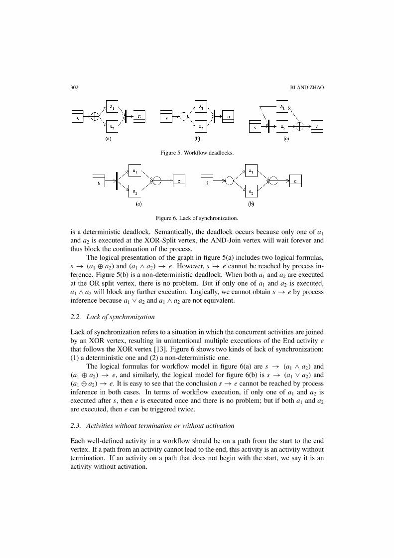
302 BI AND ZHAO
Figure 5. Workflow deadlocks.
Figure 6. Lack of synchronization.
is a deterministic deadlock. Semantically, the deadlock occurs because only one of a1
and a2 is executed at the XOR-Split vertex, the AND-Join vertex will wait forever andthus block the continuation of the process.
The logical presentation of the graph in figure 5(a) includes two logical formulas,s → (a1 ⊕ a2) and (a1 ∧ a2) → e. However, s → e cannot be reached by process in-ference. Figure 5(b) is a non-deterministic deadlock. When both a1 and a2 are executedat the OR split vertex, there is no problem. But if only one of a1 and a2 is executed,a1 ∧ a2 will block any further execution. Logically, we cannot obtain s → e by processinference because a1 ∨ a2 and a1 ∧ a2 are not equivalent.
2.2. Lack of synchronization
Lack of synchronization refers to a situation in which the concurrent activities are joinedby an XOR vertex, resulting in unintentional multiple executions of the End activity e
that follows the XOR vertex [13]. Figure 6 shows two kinds of lack of synchronization:(1) a deterministic one and (2) a non-deterministic one.
The logical formulas for workflow model in figure 6(a) are s → (a1 ∧ a2) and(a1 ⊕ a2) → e, and similarly, the logical model for figure 6(b) is s → (a1 ∨ a2) and(a1 ⊕ a2) → e. It is easy to see that the conclusion s → e cannot be reached by processinference in both cases. In terms of workflow execution, if only one of a1 and a2 isexecuted after s, then e is executed once and there is no problem; but if both a1 and a2
are executed, then e can be triggered twice.
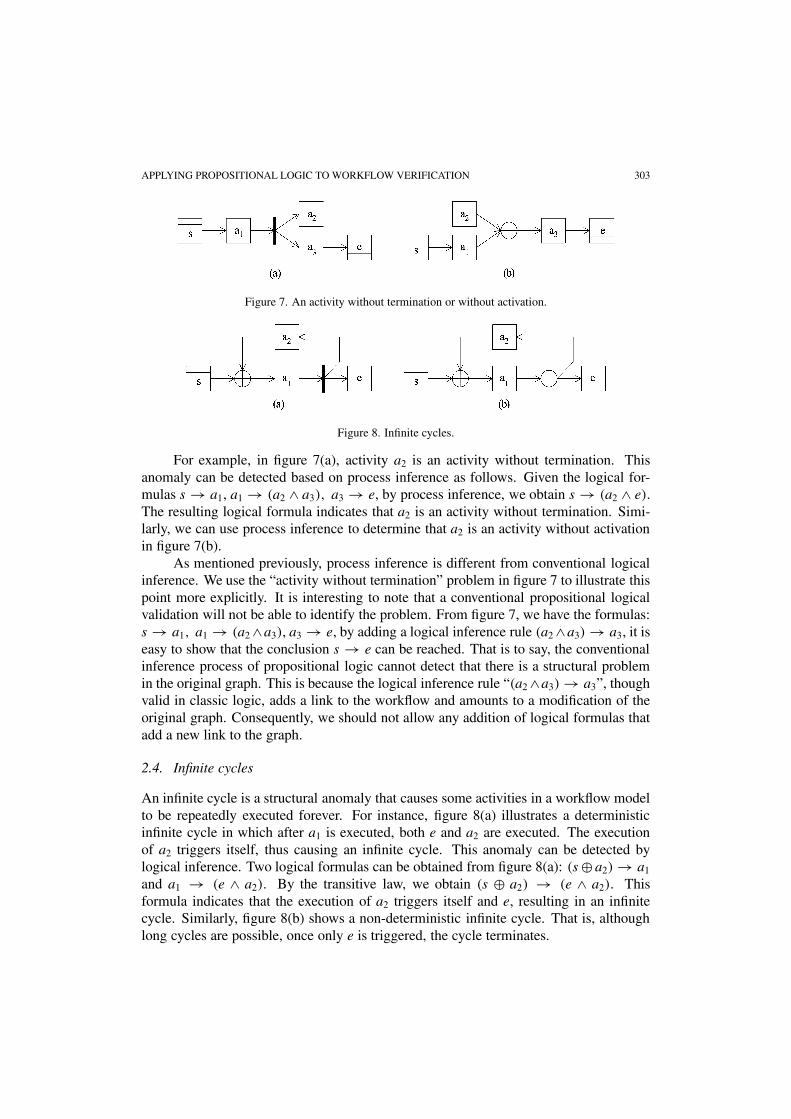
2.3. Activities without termination or without activation
Each well-defined activity in a workflow should be on a path from the start to the endvertex. If a path from an activity cannot lead to the end, this activity is an activity withouttermination. If an activity on a path that does not begin with the start, we say it is anactivity without activation.
APPLYING PROPOSITIONAL LOGIC TO WORKFLOW VERIFICATION 303
Figure 7. An activity without termination or without activation.
Figure 8. Infinite cycles.
For example, in figure 7(a), activity a2 is an activity without termination. Thisanomaly can be detected based on process inference as follows. Given the logical for-mulas s → a1, a1 → (a2 ∧ a3), a3 → e, by process inference, we obtain s → (a2 ∧ e).The resulting logical formula indicates that a2 is an activity without termination. Simi-larly, we can use process inference to determine that a2 is an activity without activationin figure 7(b).
As mentioned previously, process inference is different from conventional logicalinference. We use the “activity without termination” problem in figure 7 to illustrate thispoint more explicitly. It is interesting to note that a conventional propositional logicalvalidation will not be able to identify the problem. From figure 7, we have the formulas:s → a1, a1 → (a2 ∧a3), a3 → e, by adding a logical inference rule (a2 ∧a3) → a3, it iseasy to show that the conclusion s → e can be reached. That is to say, the conventionalinference process of propositional logic cannot detect that there is a structural problemin the original graph. This is because the logical inference rule “(a2 ∧a3) → a3”, thoughvalid in classic logic, adds a link to the workflow and amounts to a modification of theoriginal graph. Consequently, we should not allow any addition of logical formulas thatadd a new link to the graph.
2.4. Infinite cycles
An infinite cycle is a structural anomaly that causes some activities in a workflow modelto be repeatedly executed forever. For instance, figure 8(a) illustrates a deterministicinfinite cycle in which after a1 is executed, both e and a2 are executed. The executionof a2 triggers itself, thus causing an infinite cycle. This anomaly can be detected bylogical inference. Two logical formulas can be obtained from figure 8(a): (s ⊕ a2) → a1
and a1 → (e ∧ a2). By the transitive law, we obtain (s ⊕ a2) → (e ∧ a2). Thisformula indicates that the execution of a2 triggers itself and e, resulting in an infinitecycle. Similarly, figure 8(b) shows a non-deterministic infinite cycle. That is, althoughlong cycles are possible, once only e is triggered, the cycle terminates.

304 BI AND ZHAO
It is worth noting that the logic-based verification can be used to test the reachabil-ity of a workflow model as well. Reachability between any two vertices is defined as theconnectivity between them [10]. In our context, we define the reachability of a workflowmodel as the connectivity between any vertex and the end vertex. Note that three ofthe aforementioned anomalies, deadlock, lack of synchronization, and activity withoutactivation or termination can cause incomplete reachability in a workflow model.
2.5. The correctness of logic-based verification
We present one lemma and one theorem to illustrate formally the correctness of thelogic-based workflow verification. Lemma 1 is based on the anomalies defined above,and theorem 1 specifies the sufficient condition for an acyclic workflow to be correct.
Lemma 1. Given an acyclic workflow W = (f1, f2, . . . , fn) that contains at least oneanomaly such as deadlock, lack of synchronization, and activity without termination,the corresponding logical representation must contain at least one logical formula thatcauses the inference by substitution to fail, or at least one original or intermediate for-mula that contains a pattern of anomaly, such as deadlock.
Discussion. As we have explained in the previous subsections, each type of workflowanomalies (not including infinite cycles) can be detected based on their logical expres-sions. First, a deadlock (section 2.1) or lack of synchronization (section 2.2) anomalycauses inference by substitution to fail because of asymmetry of logical operators. Sec-ond, an activity without termination can cause a logical formula to fail to link to otherformulas that lead to the end vertex e. Third, certain original or intermediate formu-las can also contain anomalies such as deadlocks (section 2.1). Consequently, lemma 1is correct. Note that since we are dealing with acyclic workflows here, we need notconsider the infinite cycle anomalies. �
Theorem 1. A workflow model W = (f1, f2, . . . , fn) is free from anomalies if allformulas f1, f2, . . . , fn are combined by substitution into s → e.
Proof by contradiction. Assume theorem 1 is false, that is, W contains at least oneanomaly. By lemma 1, there is at least one formula in {f1, f2, . . . , fn} that causes theinference to fail or contains a pattern of anomaly. Consequently, it is impossible toachieve the conclusion s → e. This contradicts the given condition that s → e has beenreached. Thus, theorem 1 must be true if the condition holds. �
3. Logic-based workflow verification algorithm
In this section, we first present the verification algorithm and then illustrate it using areal world workflow example.

APPLYING PROPOSITIONAL LOGIC TO WORKFLOW VERIFICATION 305
3.1. The verification algorithm
The following notations are used in the algorithm:
• W : a workflow model;
• s: start vertex;
• e: end vertex;
• ai : an activity;
• �: a set of logical formulas for a given workflow;
• �: a set of terminal logical formulas resulting from inference;
• ϕ(x1, x2, x3, . . . , xd): a logical expression in the form of ((((x1 θ x2) θ x3) θ · · ·) θ xd),θ ∈ {∧,⊕,∨}, d � 1. Note that x1, x2, x3, . . . , xd can be either an activity or alogical expression;
• f : a logical formula in the form lhs(f ) → rhs(f ), and can also be written f (lhs(f ),
rhs(f ));
• lhs(f ): the left hand side (LHS) of formula f in the form of ϕ(p1, p2, p3, . . . , pk),k � 1;
• rhs(f ): the right hand side (RHS) of formula f in the form of ϕ ϕ(q1, q2, q3, . . . , qm),m � 1;
• �: an exclusive disjunction of activities in form of (((a1 ⊕ a2) ⊕ · · ·) ⊕ ac), c � 1;
• contains: a function indicating that an expression subsumes another expression, forinstance, lhs(f ) = ((a1 ∧ a2) ∧ a3) ∧ a4 contains rhs(f ′) = (a1 ∧ a2) ∧ a3.
We use an example to illustrate some of these notations. Given a formula
f1 = (((a1 ∧ a2) ∧ a3) ∧ a4) → (a5 ⊕ a6),
we can write
lhs(f1) = ϕ(p1, p2, p3, p4) = (((a1 ∧ a2) ∧ a3) ∧ a4),
where p1 = a1, p2 = a2, p3 = a3, p4 = a4 and
rhs(f1) = ϕ(q1, q2) = (a5 ⊕ a6),
where q1 = a5, and q2 = a6.The way of expressing lhs(f1) and rhs(f1) as exemplified here enables us to specify
various matching conditions between formulas. For instance, given another formula
f2 = (ϕ(p∗1) → ϕ(q∗
i )) = (a5 → (a7 ⊕ a8)),
where p∗1 = a5 and q∗
1 = (a7 ⊕ a8). We can say that the RHS of f1, rhs(f1) contains theLHS of f2, lhs(f2). Note that rhs(f1) = ϕ(q1, q2), lhs(f2) = ϕ(p∗
1) where q1 = p∗1 =

306 BI AND ZHAO
a5, and the superscript ∗ indicates that the expression is from formula f2. Consequently,formula f1 and formula f2 can be merged into
f ′1 = (ϕ(p1, p2, p3, p4) → ϕ(q1, q2)) = (ϕ(p1, p2, p3, p4) → ϕ(q∗
1 , q2))
= ((((a1 ∧ a2) ∧ a3) ∧ a4) → ((a7 ⊕ a8) ⊕ a6)),
where q∗1 = (a7 ⊕ a8) from the RHS of f2.
The logic-based workflow verification algorithm consists of the following proce-dures:
PROCEDURE Verify (�) {� = ∅ // Initialize the set of resulting formulasdo { // Start the overall process inference
do { // Start process inference for the remaining logical formulasfor any f ∈ �
� = � − f
Lhs_match(f ) = MatchLHS(f,�)Rhs_match(f ) = MatchRHS(f,�)f ′ = Merged(f, Lhs_match(f ), Rhs_match(f ))
� = � + f ′ − Lhs_match(f ) − Rhs_match(f )
} while (f = f ′ AND � = ∅) // Found a resulting formula� = � + f ′ // Insert the resulting formula into a set
} while (� = ∅)Identify(�) // Identify potential anomalies
}
PROCEDURE MatchLHS(f,�) { // Search for formulas in � that matches the LHS of f
Lhs_match(f ) = ∅
for each f ′ ∈ � {if (lhs(f ′) contains rhs(f ′) OR rhs(f ′) contains lhs(f )) {
Lhs_match(f ) = Lhs_match(f ) + f ′� = � − f ′
}} return Lhs_match(f )
}
PROCEDURE MatchRHS(f,�) { // Search for formulas in � that matches the RHS of f
Rhs_match(f ) = ∅
for each f ′ ∈ � {if (lhs(f ′) contains rhs(f ) OR rhs(f ) contains lhs(f ′)) {
Rhs_match(f ) = Rhs_match(f ) + f ′� = � − f ′
}} return Rhs_match(f )
}

APPLYING PROPOSITIONAL LOGIC TO WORKFLOW VERIFICATION 307
PROCEDURE Merge(f, Lhs_match(f ), Rhs_match(f )) { // Merge formula f with itsmatching formulas
for each f ′ ∈ Lhs_match(f ) {if (lhs(f ) contains rhs(f ′)) {
lhs(f ) = ϕ(p1, p2, . . . , lhs(f ′), . . . , pk)
// replace part of the LHS of f by the LHS of f ′ based on the transitivelaw
} else {rhs(f ′) = ϕ(q1, q2, . . . , t (f ), . . . , qm)
// replace part of the RHS of f ′ by the RHS of f based on the transitive lawf = f ′
}}for f ′ ∈ Rhs_match(f ) {
if (rhs(f ) contains lhs(f ′)) {rhs(f ) = ϕ(q1, q2, . . . , rhs(f ′), . . . , qm)
} else {lhs(f ′) = ϕ(p1, p2, . . . , lhs(f ), . . . , pk)
f = f ′}
} return f
}
PROCEDURE Identify(�) { // Identify potential anomalies in resulting formulasif(|�| = 1) {
for f ∈ �
if (f = (s, e) OR f = ((s ⊕ �), (e ⊕ �)) {print “W contains no anomaly”
}} else {
for each f ∈ � {for each f ′ ∈ �, f ′ = f {
if (lhs(f ′) contains (((a1 ⊕ a2) ⊕ · · ·) ⊕ ar ) AND rhs(f ) contains(((a1 ∧ a2) ∧ · · ·) ∧ ar)) {
print “W contains lack of synchronization at a1, a2, . . . , ar”} else if (lhs(f ′) = ϕ(p1, p2, . . . , (((a1 ∧ a2) ∧ · · ·) ∧ ar), . . . , pk) AND
rhs(f ) = (q1, q2, . . . , (((a1 ⊕ a2) ⊕ · · ·) ⊕ ar), . . . , qm)) {print “W contains deadlock at a1, a2, . . . , ar”
}}if (f = ((s ∧ ϕ), (e ∧ ϕ))) { // ϕ is a valid logical expression
print “W contains a deadlock at ϕ”}if (f = ((s ⊕ ϕ), (e ∧ ϕ)) { print “W contains a deterministic infinite cycle at ϕ” }if (f = ((s ⊕ ϕ), (e ∧ ϕ))) { print “W contains a non-deterministic infinite cycle
at ϕ” }

308 BI AND ZHAO
if (f = (s, (e ∧ ϕ)) OR f = (s, (e ⊕ ϕ)) OR f = (s, (e ∨ ϕ))) {print “W contains an activity without termination at �”
}if f = ((s ∧ ϕ), e) OR f = ((s ⊕ ϕ), e) OR f = ((s ∨ ϕ), e))){
print “W contains an activity without activation at �”}
}}
}
The complexity of the algorithm can be estimated as follows. Although the proce-dure Verify contains two levels of do-loops, they combine together into one loop sincethe number of outer loop iteration is equal to the number of resulting formulas, andthe number of inner loop iteration depends on the number of formulas in each resultingformula of process inference. At one extreme, when there is no anomaly found in theworkflow, there will be only one resulting formula. In this case, the inner loop will iter-ate at most (n−1) times, and the outer loop will iterate only once, where n is the numberof constructs in the workflow model as defined in figure 2.
In sum, the two do-loops collectively contain n − 1 steps of iteration since at thefirst iteration the initial dimension of � is n − 1. Further, Procedures MatchLHS( )and MatchRHS( ) also contain loops, with a maximum 2(n − 1) number of compar-isons initially and decreasing thereafter. Consequently, the worst case complexity of thealgorithm is proportional to 2(n − 1)2, or approximately O(n2).
3.2. Handling cyclic workflow models
In the verification algorithm, formulas f1, f2, . . . , fn are transformed through processinference to reach the conclusion s → e if the given workflow W is acyclic. However,if W is cyclic, we will not be able to reach s → e. Instead, we need a new form ofconclusion as explained next.
As shown in figure 9, if a correct workflow contains a single cycle, process infer-ence can reduce the workflow model to figure 9(a), and if a correct workflow containsmultiple cycles, process inference can reduce the workflow model similar to figure 9(b).
Figure 9. Basic cycles.

APPLYING PROPOSITIONAL LOGIC TO WORKFLOW VERIFICATION 309
Figure 9(a) is a basic cycle that can be expressed as (s ⊕ a1) → (e ⊕ a1), and fig-ure 9(b) contains three basic cycles that can be represented by (s ⊕ (a1 ⊕ (a2 ⊕ a3))) →(s ⊕ (a1 ⊕ (a2 ⊕ a3))), which can be generalized as (s ⊕ �) → (e ⊕ �), where� = a1 ⊕ (a2 ⊕ a3), an exclusive disjunction of two or more activities.
Note that we do not deal with nested cycles in this paper. However, any nestedcycles can be dealt with iteratively using the algorithm provided above. That is, we firstdeal with the simple cycle (a cycle that does not contain a cycle in it), and then reducethe verified portion to a vertex. The same algorithm can then be applied to deal withhigher order cycles.
We prove the correctness of verification in the case of cyclic workflows next:
Lemma 2. Given a cyclic workflow W = (f1, f2, . . . , fn) that contains at least oneanomaly such as deadlock, lack of synchronization, activity without termination, andinfinite cycles, the corresponding logical representation must contain at least one logi-cal formula that causes the inference by substitution to fail, or at least one original orintermediate formula that contains a pattern of anomaly, such as deadlock or infinitecycle.
Discussion. Similar to lemma 1, each type of workflow anomalies can be detectedbased on their logical expressions. In addition to anomalies found in acyclic workflows,infinite cycles (section 2.4) can also be detected based on the original or intermediatelogical patterns in a cyclic workflow. Consequently, lemma 2 is correct. �
Theorem 2. A cyclic workflow model W = (f1, f2, . . . , fn) is free from anomaliesif all formulas f1, f2, . . . , fn are combined by substitution into (s ⊕ �) → (e ⊕ �),where s is the Start vertex of W and e the End vertex, and � is a formula with exclusivedisjunction of activities.
Proof by contradiction. Assume theorem 2 is false, that is, W contains at least oneanomaly. By lemma 2, there is at least one formula in {f1, f2, . . . , fn} that causes theinference to fail or contains a pattern of anomaly. Consequently, it is impossible toachieve the conclusion (s ⊕ �) → (e ⊕ �). This contradicts the given condition. Thus,theorem 2 must be true. �
Note that theorem 2 proves the correctness of logic-based process inference, butnot its completeness. In fact, the current verification algorithm does not handle work-flow models that contain certain types of overlapping patterns. An overlapping patternis a structure in which two or more routing vertices share two or more immediatelypreceding (or parent) routing vertices. For instance, figure 10 illustrates an overlap-ping pattern in which the routing vertices r4 and r5 share two parent routing vertices,r2 and r3.
Applying process inference to the logical formulas obtained from this workflowmodel, we get two formulas, s → ((a1 ∧a2)⊕(a3 ∧a4)) and ((a1 ⊕a3)∧(a2 ⊕a4)) → e,

310 BI AND ZHAO
Figure 10. An overlapping pattern.
which cannot be further transformed using existing logical rules. But, it can be shownthat this workflow is structurally correct. In other words, not all overlapping patternswill present a problem. However, for example, if all AND routing vertices in figure 10are replaced with XOR vertices, the process inference algorithm will be able to verify itscorrectness. Detailed analyses of overlapping workflow patterns and their verificationare beyond the scope of this paper.
3.3. A workflow example
We use an online hotel reservation workflow (figure 11) to illustrate the verificationalgorithm. The hotel reservation company allows a customer to name her or his pricefirst and then contacts its partner hotels to find whether any hotels accept the requestedreservation. For simplicity, we limit the number of hotels to three.
We will show that this model contains structural anomalies, assuming that the con-version rules given in table 2 are used to create the logical formulas as shown in table 13.
Applying the process inference laws defined in section 1, the logical formulas intable 13 can be transformed using logical rules. In table 14, for example, the associativelaw ((p ⊕ q)⊕ r) ↔ (p ⊕ (q ⊕ r)) is first applied to formula 2, ((a1 ⊕ a4)⊕ a16) → a2,to obtain (a1 ⊕ (a4 ⊕ a16)) → a2. Then the transitive law p → q, (q ⊕ r) → s �(p ⊕ r) → s is applied to (a1 ⊕ (a4 ⊕ a16)) → a2 and formula 1, s → a1, to generate(s ⊕ (a4 ⊕ a16)) → a2. Finally, the associative law is applied again to (s⊕(a4 ⊕a16) →a2 to produce formula 14, ((s⊕a4)⊕a16) → a2. Other formulas in table 14 are obtainedin a similar way.
Now, we explain briefly how to verify the example using the verification algorithm.Initially the formula set � contains 13 formulas as listed in table 13. Starting with for-mula 1, s → a1, for instance, the procedure MatchRHS finds that the LHS of formula 2,((a1 ⊕ a4) ⊕ a16), contains the RHS of formula 1, a1. Then, the procedure Mergemerges the LHS of formula 1, s, into the LHS of formula 2 and obtains formula 14,((s ⊕ a4) ⊕ a16) → a2, in table 14.
Continuing the algorithm, we derive the resulting formula set � containing 3 for-mulas, that is, formulas 18, 21, and 22 in table 14. Two anomalies, deadlock and lack ofsynchronization, are found among these three remaining formulas when the procedure

APPLYING PROPOSITIONAL LOGIC TO WORKFLOW VERIFICATION 311
Fig
ure
11.
Aw
rong
lyde
sign
edw
orkfl
owm
odel
for
the
hote
lres
erva
tion
proc
ess.

312 BI AND ZHAO
Table 13The logical formulas from figure 11.
Formula No. Formula Formula No. Formula
1 s → a1 8 a9 → (a12 ⊕ a13)
2 ((a1 ⊕ a4) ⊕ a16) → a2 9 (((a10 ∧ a11) ∧ a12) ∧ a13) → a143 a2 → (a3 ⊕ a6) 10 a14 → (a15 ⊕ a18)
4 a3 → (a4 ⊕ a5) 11 a15 → (a16 ⊕ a17)
5 a6 → ((a7 ∨ a8) ∨ a9) 12 a18 → (a19 ∧ a20)
6 a7 → (a10 ⊕ a13) 13 (((a5 ⊕ a17) ⊕ a19) ⊕ a20) → e
7 a8 → (a11 ⊕ a13)
Table 14Transformation of logical formulas in table 13.
Formula No. Transformation Sources
14 ((s ⊕ a4) ⊕ a16) → a2 1, 215 ((s ⊕ a4) ⊕ a16) → (a3 ⊕ a6) 3, 1416 ((s ⊕ a4) ⊕ a16) → ((a4 ⊕ a5) ⊕ a6) 4, 1517 ((s ⊕ a4) ⊕ a16) → ((a4 ⊕ a5) ⊕ ((a7 ∨ a8) ∨ a9)) 5, 1618 ((s ⊕ a4) ⊕ a16) → ((a4 ⊕ a5) ⊕ (((a10 ⊕ a13) ∨ (a11 ⊕ a13)) ∨ (a12 ⊕ a13))) 6, 7, 8, 1719 (((a10 ∧ a11) ∧ a12) ∧ a13) → (a15 ⊕ a18) 9, 1020 (((a10 ∧ a11) ∧ a12) ∧ a13) → ((a16 ⊕ a17) ⊕ a18) 11, 1921 (((a10 ∧ a11) ∧ a12) ∧ a13) → ((a16 ⊕ a17) ⊕ (a19 ∧ a20)) 12, 2022 (((a5 ⊕ a17) ⊕ a19) ⊕ a20) → e 13
Identify is applied to them. Because � contains three terminal formulas, i.e., formulasthat cannot be further merged, it must contain at least one anomaly. The AND relation-ships among a10, a11, a12, and a13 in the second part (formulas 9 through 12) do notmatch the OR and XOR relationships among these four activities in the first part (for-mulas 1 through 8). This indicates that the model contains a deadlock around these fouractivities. Also, the XOR relationship between a19 and a20 in the third part (formula 13)does not match their AND relationship in the second part. This implies that a lack ofsynchronization problem occurs around a19 and a20.
These two anomalies are corrected as follows: (1) add activities a21 through a25 andchange the AND-Join among a10, a11, a12, and a13 into XOR-Joins and OR-Join amonga10 through a13 and a21 through a25, and (2) add activity a26 and change the XOR-Joinbetween a19 and a20 into an AND-Join. The new model is shown in figure 12, and itslogical formulas are given in table 15.
Applying the verification algorithm to the new set of formulas, we obtain a singleformula (s ⊕ (a4 ⊕ a16)) → (e ⊕ (a4 ⊕ a16)). The resulting formula can be repre-sented graphically as a workflow model consisting of two basic cycles without structuralanomaly (figure 13). According to theorem 2, we can declare that the revised model infigure 12 contains no structural anomaly.
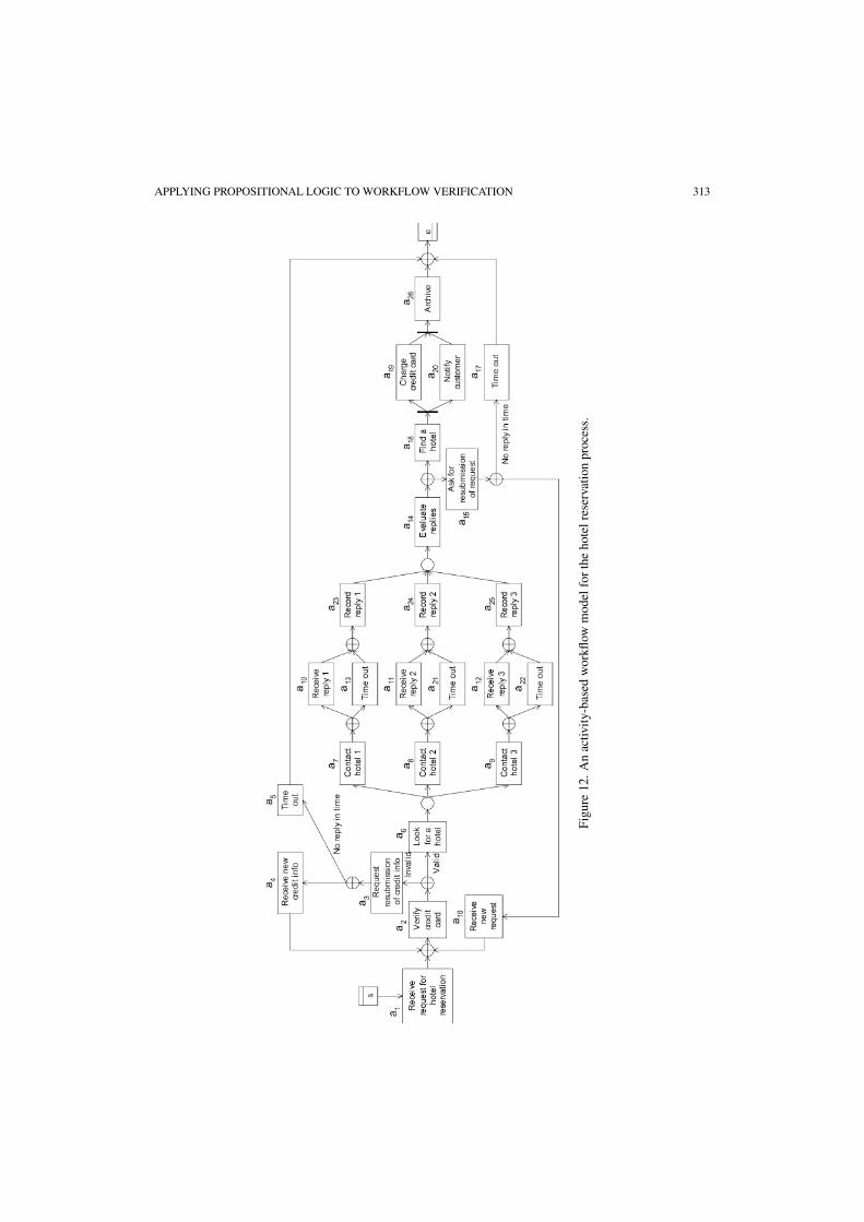
APPLYING PROPOSITIONAL LOGIC TO WORKFLOW VERIFICATION 313
Fig
ure
12.
An
activ
ity-
base
dw
orkfl
owm
odel
for
the
hote
lres
erva
tion
proc
ess.

314 BI AND ZHAO
Table 15Logical formulas obtained by the conversion of workflow model in figure 12.
Formula No. Formula Formula No. Formula
1 s → a1 10 (a11 ⊕ a21 → a242 ((a1 ⊕ a4) ⊕ a16) → a2 11 (a12 ⊕ a22) → a253 a2 → (a3 ⊕ a6) 12 ((a23 ∨ a24) ∨ a25) → a144 a3 → (a4 ⊕ a5) 13 a14 → (a15 ⊕ a18)
5 a6 → ((a7 ∨ a8) ∨ a9) 14 a15 → (a16 ⊕ a17)
6 a7 → (a10 ⊕ a13) 15 a18 → (a19 ∧ a20)
7 a8 → (a11 ⊕ a21) 16 (a19 ∧ a20) → a268 a9 → (a12 ⊕ a22) 17 ((a5 ⊕ a17) ⊕ a26) → e
9 (a10 ⊕ a13) → a23
Figure 13. A workflow model consisting of two basic cycles.
4. Related work on workflow verification
We review three existing workflow verification approaches, Petri nets, graph reduction,and matrix-based, and compare them with the logic-based verification method.
4.1. Petri nets
Petri nets have been used to represent and verify workflow models [1–3,5,11]. A Petri netconsists of three main components: transitions that represent activities or tasks, placesthat hold tokens representing states, and directed arcs that link transitions and places.The existing research on Petri-net-based workflow is related to a concept called work-flow net (WF-net) [1]. A Petri net is a WF-net if and only if (1) it has a source placeand a sink place and (2) if a transition that connects the sink place and the source place,the resulting Petri net is strongly connected. The verification of WF-nets focuses onverifying the soundness of workflows and related issues such as liveness, boundedness,safeness, deadlock, livelock, and dead activity [1–3].
The main advantages of the Petri net formalism include a formal theory base, a to-ken-based representation of workflow states, and its rigorous analysis and verificationtools. Tokens play a key role in simulating control flows within a workflow model, rep-resenting states of the model at any given time, and providing an instrument to verifythe model. Currently, most existing WfMSs do not use Petri nets as the modeling for-malism [2,13]. Since Petri nets translate workflows into transitions, places, and tokens,

APPLYING PROPOSITIONAL LOGIC TO WORKFLOW VERIFICATION 315
Petri-net-based workflow representation is not as easy to understand as those based onactivities and explicit control constructs.
4.2. Graph reduction
Graph reduction was developed to identify two types of structural anomalies - deadlockand lack of synchronization [13]. It does so by removing the definitely correct structuresthat do not contain any structural anomaly, thus reducing the workflow model. This isaccomplished by iteratively applying five reduction rules to remaining vertices in themodel. The five reduction rules are terminal reduction, sequential reduction, adjacentreduction, closed reduction, and overlapping reduction. The model cannot be completelyreduced to an empty graph, if it contains any of these two types of anomalies.
Graph reduction improves computational efficiency by reducing the graph itera-tively. The worst case complexity of the main graph reduction algorithm is O(n2). Themain weakness of the graph reduction technique is that it is not applicable to workflowmodels that contain cycles [13]. Furthermore, although graph reduction can verify a spe-cial overlapping structure, it may not be able to handle general overlapping structures.
4.3. Matrix-based approach
The matrix-based workflow verification integrates process abstraction and process veri-fication [6,7]. This approach uses the adjacency matrix to represent the workflow modeland applies the concept of inline block to reduce computational complexity. An inlineblock is a collection of vertices satisfying the blocked transition property and is freefrom structural conflicts to verify workflow models. The blocked transition property re-quires that any inward transition to the inline block can only occur to the start vertexand that any outward transition from the inline block can only occur at the end node.A matrix-based algorithm is applied to identifying subsets of a process model that canbe represented as inline blocks.
So far, the matrix-based approach has been shown to be effective in identifyingdeadlock and lack of synchronization problems in cyclic workflow models. Addition-ally, this approach can verify complex workflow structures (including any overlappingworkflow structures) by analyzing all instance flows within each inline block. However,like most existing WfMSs, this approach has not addressed how to handle workflowmodels that contain OR vertices. In addition, the computational efficiency of matrix-based verification has not been reported in the literature.
4.4. Comparison of workflow verification approaches
The three approaches are compared with the logic-based verification in table 16, whereOR vertices are OR-Split and OR-Join vertices, ‘n/a’ means that the information isnot found in the referenced papers. A state-based approach can capture the states ofa workflow, whereas an activity-based approach does not model the states of a work-flow.

316 BI AND ZHAO
Table 16Comparisons of four workflow verification approaches.
Petri nets Graph reduction Matrix-based Logic-based
Model State-based Activity-based Activity-based Activity-based
Anomalies • Deadlock • Deadlock • Deadlock • Deadlockdetected • Liveness • Lack of • Lack of • Lack of
• Boundedness synchronization synchronization synchronization• Safeness • Activity without• Livelock termination• Dead activity • Infinite cycle
Cyclic models Yes No Yes Yes
OR vertices n/a n/a n/a Yes
Overlapping Yes Yes (partially) Yes Somestructures
Complexity n/a O(n2) n/a O(n2)
Tools created Woflan FlowMake n/a n/a
Compared with other activity-based verification approaches, logic-based verifica-tion can detect more types of workflow anomalies with acceptable computational com-plexity and is the only method that considers workflow models that contain OR vertices.This is an important feature since commercial workflow systems such as SAP R/3 Work-flow, Verve Workflow, and Forte Conductor have implemented the concept of OR-Splitand OR-Join [5]. However, as discussed earlier, the logic-based verification algorithmpresented in this paper cannot handle workflow models that contain certain overlappingrouting vertices; an extended logical verification method that is based on instance analy-sis will resolve this issue.
5. Conclusion
Workflow verification has been known to be an important, but hard problem to re-solve. As such, few commercial workflow management systems provide workflow ver-ification tools. In this paper, we developed a logic-based method for detecting work-flow anomalies by process inference in the presence of cyclic structures. We alsoproposed an activity-based modeling paradigm that can capture the basic features ofcommercial workflow models. In order to make the activity-based modeling paradigmmore powerful, we extended the WfMC standards with OR-Split and OR-Join con-structs.
We applied propositional logic to the workflow verification with two extensions.First, we discovered that conventional truth table is inconvenient when proving newlogical rules needed for process inference, and therefore, we proposed the concept ofconstrained truth table as a deviation from classic propositional logic. Second, we found
APPLYING PROPOSITIONAL LOGIC TO WORKFLOW VERIFICATION 317
that conventional logical inference rules cannot be applied in workflow verification if arule causes a modification to the workflow graph. Consequently, process inference is notthe same as the classical logical inference as we exemplified in the paper.
We have proven theoretically that any workflow model that passes the verificationis guaranteed to be free from the types of anomalies that have been defined in the paper.However, our verification algorithm cannot handle certain overlapping workflow patternsas aforementioned. We are currently working on an extended algorithm that has shownpromising results towards eliminating this limitation.
We believe that we have made a strong case for applying propositional logic toworkflow verification, and we hope that the presented results can stimulate more researchin workflow verification. In our future research, we plan to:
• Extend the logic-based workflow verification to handle overlapping structures. Ourinitial investigation has shown that instance-based process inference can handle anycomplex workflow structures.
• Design and implement a logic engine that can verify workflow models automatically,which will help transfer our research results to industrial strength applications.
Acknowledgements
We appreciate the comments by two anonymous reviewers and the guest editor, whichhelped improve the quality of this paper significantly.
References
[1] W.M.P. van der Aalst, Verification of workflow nets, in: The 18th International Conference on Appli-cation and Theory of Petri Nets, Lecture Notes in Computer Science, Vol. 1248 (1997) pp. 407–426.
[2] W.M.P. van der Aalst, The application of Petri nets to workflow management, Journal of Circuits,Systems and Computers 8(1) (1998) 21–66.
[3] W.M.P. van der Aalst, Three good reasons for using a Petri-net-based workflow management sys-tem, Information and Process Integration in Enterprises: Rethinking Documents (Kluwer Academic,Dordrecht, 1999) pp. 161–182.
[4] W.M.P. van der Aalst and Arthur H.M. ter Hofstede, Verification of workflow task structures: A Petri-net-based approach, Information Systems 25(1) (2000) 43–69.
[5] N.R. Adam, V. Atluri and W.K. Huang, Modeling and analysis of workflows using Petri nets, Journalof Intelligent Information Systems 10(2) (1998) 131–158.
[6] Y. Choi and J.L. Zhao, Matrix-based abstraction and verification for e-business processes, in: Pro-ceedings of the 1st Workshop on e-Business (2002).
[7] Y. Choi and J.L. Zhao, Handling cycles in workflow verification by feedback identification and parti-tion, in: Proceedings of the 2003 International Conference on Information and Knowledge Engineer-ing, Las Vegas, NV (June 23–26, 2003).
[8] D. Georgakopoulos, M. Hornick and A. Sheth, An overview of workflow management: From processmodeling to workflow automation infrastructure, Distributed and Parallel Databases 3(2) (1995) 119–153.
[9] A.M. Law and D. Kelton, Simulation Modeling and Analysis, 3rd edn. (McGraw-Hill Higher Educa-tion, 2000).

318 BI AND ZHAO
[10] T. Maruta, S. Onoda, Y. Ikkai, T. Kobayashi and N. Komoda, A deadlock detection algorithm forbusiness processes workflow models, in: IEEE International Conference on Systems, Man, and Cy-bernetics, Vol. 1 (11–14 October 1998) pp. 611–616.
[11] T. Murata, Petri nets: Properties, analysis and applications, Proceedings of the IEEE 77(4) (1989)541–580.
[12] J. Nolt, D. Rohatyn and A. Varzi, Schaum’s Outline of Logic, 2nd edn. (McGraw-Hill, 1998).[13] W. Sadiq and M.E. Orlowska, Analyzing process models using graph reduction techniques, Informa-
tion Systems 25(2) (2000) 117–134.[14] M. Sipser, Introduction to the Theory of Computation (PWS, 1997).[15] E.A. Stohr and J.L. Zhao, Workflow automation: Overview and research issues, Information Systems
Frontiers: Special Issue on Workflow Automation 3(3) (2001) 281–296.[16] WfMC, Workflow management coalition terminology & glossary (WFMC-TC-1011, Issue 3.0),
Workflow Management Coalition (1999).[17] D. Wodtke, J. Weißenfels, G. Weikum, A. Kotz Dittrich and P. Muth, The MENTOR workbench for
enterprise-wide workflow management, in: SIGMOD Conference (1997) pp. 576–579.