Embed Size (px)
Citation preview
World Engineering & Applied Sciences Journal 7 (2): 124-134, 2016ISSN 2079-2204© IDOSI Publications, 2016DOI: 10.5829/idosi.weasj.2016.7.2.22629
Corresponding Author: A. Balamurugan, Department of EEE, Surya College of Engineering & Technology, Villupuram, Tamil Nadu, India.
124
Fuzzy Gain Scheduled Pi Controller for Resonant Power ConverterFed Hybrid Electric Vehicle with Bldc Motor Drive
A. Balamurugan and S. Ramkumar1 2
Department of EEE, Surya College of Engineering & Technology,1
Villupuram, Tamil Nadu, IndiaDepartment of EEE, Sri Krishna College of Engineering and Technology,2
Coimbatore, Tamil Nadu, India
Abstract: Over the years, it has seen the power conditioning move from simple, but extravagant linearregulators, through early low frequency pulse-width modulated systems, to high-frequency square waveconverters, which pack the same power handling capabilities of earlier designs into a fraction of their size andweight. At present, a novel attack is upon us the resonant mode converter and while extending new benefitsin performance, size and cost, this new technology brings with it an added dimension of complexity. The aimof this paper is to provide a system for manipulating the speed of a Brushless DC motor (BLDC) in aHybrid-Electric Vehicle fed resonant mode inverter. Resonant inverter is used for DC-AC conversion withcurrent resonance. The inverter used to regulate voltage and fed into the BLDC motor through a motor drivercircuit. In this paper, the resonant inverter fed BLDC motor drive for hybrid-electric vehicle system simulatedusing An MATLAB/Simulink software tool. PI controller and Fuzzy Gain Scheduled PI controller are used forclosed-loop control of the projected scheme.
Key words: BLDC motor Electric vehicle Fuzzy Gain Scheduled PI controller PI controller ResonantInverter
INTRODUCTION telecommunication and aerospace applications. It has
Recently because environmental pollution and the switching losses, reduced reliability, electromagneticenergy crisis are rising globally, most industrialized interference (EMI) and acoustic noise at high frequencies.countries have been trying to reduce their dependence on The series and parallel Resonant Converter circuits are theoil as an electric cars, scooters, bicycles, wheelchairs, etc. basic resonant converter topologies with two reactiveElectric vehicles (EVs) are becoming important, not only elements. The RC is found to be desirable, due to variousas an environmental measure against global warming but inherent advantages. The merits of SRC include betteralso as an industrial policy [1, 2]. For the next-generation power conversion efficiency due to the series capacitor inEVs must be secure and perform well. The propulsion the resonant network and the inherent DC blockingforce generation which strongly influences the base hit capability of the isolation transformer. Nevertheless, theand running performance of the vehicle. The faster, more load regulation is poor and output-voltage regulation atefficient, less noisy and more reliable Brushless DC no-load is not possible by switching frequency variations.motors (BLDCMs) have many advantages over brushed On the other hand, the PRC offers better no-loadDC motors and induction motors. It has a simple regulation, but suffers from poor power conversionconstruction, high efficiency, higher speed range, large efficiency due to the deficiency of a DC blocking elementstarting torque, noiseless operation, etc., [3, 4, 5]. before the isolation transformer. Hence, an RC with
The invention and evolution of various resonant three reactive components is suggested for betterpower converters (RPC) have been focused on regulation [6-10].
been set up that these converters experience high
World Eng. & Appl. Sci. J., 7 (2): 124-134, 2016
125
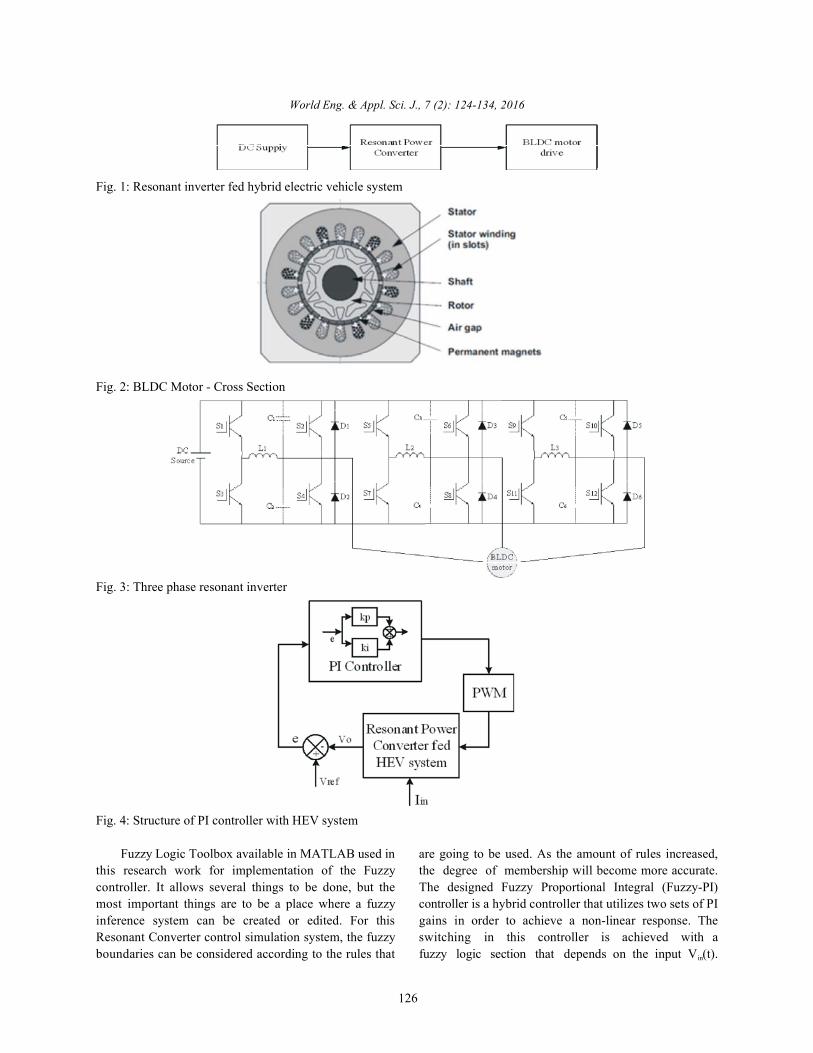
In this paper, a new circuit of resonant inverter fed The switches activate circuits L1, C1 and C2, respectiveBLDC motor control for hybrid-electric vehicle closed L2, C3 and C4 and L3, C5 and C6. These circuits areloop control is implemented using PI and fuzzy gain initialized in the instants when the current of the load isscheduled PI controller, performance parameters like too low for fast overcharging or wrong polarity forsteady state and transient analysis are analyzed. overcharging of resonant capacitors. If the current of the
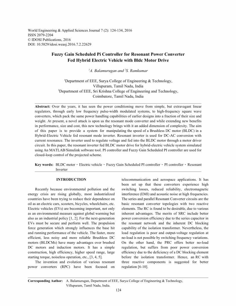
Proposed System Description: Fig. 1 shows the block overcharge without resonant circuit utilization. The maindiagram representation of the resonant inverter fed switches of the converter use zero voltage switching andHybrid-Electric Vehicle system (HEV). the auxiliary switches use zero current switching. In the
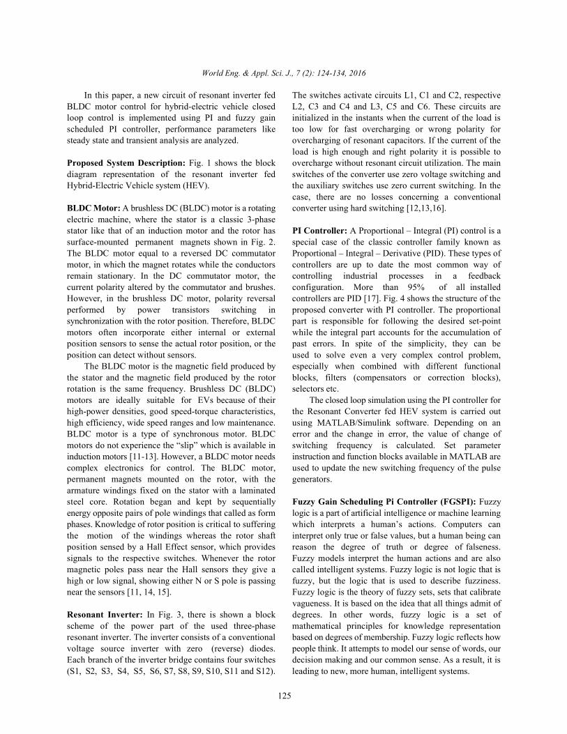
BLDC Motor: A brushless DC (BLDC) motor is a rotating converter using hard switching [12,13,16].electric machine, where the stator is a classic 3-phasestator like that of an induction motor and the rotor has PI Controller: A Proportional – Integral (PI) control is asurface-mounted permanent magnets shown in Fig. 2. special case of the classic controller family known asThe BLDC motor equal to a reversed DC commutator Proportional – Integral – Derivative (PID). These types ofmotor, in which the magnet rotates while the conductors controllers are up to date the most common way ofremain stationary. In the DC commutator motor, the controlling industrial processes in a feedbackcurrent polarity altered by the commutator and brushes. configuration. More than 95% of all installedHowever, in the brushless DC motor, polarity reversal controllers are PID [17]. Fig. 4 shows the structure of theperformed by power transistors switching in proposed converter with PI controller. The proportionalsynchronization with the rotor position. Therefore, BLDC part is responsible for following the desired set-pointmotors often incorporate either internal or external while the integral part accounts for the accumulation ofposition sensors to sense the actual rotor position, or the past errors. In spite of the simplicity, they can beposition can detect without sensors. used to solve even a very complex control problem,
The BLDC motor is the magnetic field produced by especially when combined with different functionalthe stator and the magnetic field produced by the rotor blocks, filters (compensators or correction blocks),rotation is the same frequency. Brushless DC (BLDC) selectors etc.motors are ideally suitable for EVs because of their The closed loop simulation using the PI controller forhigh-power densities, good speed-torque characteristics, the Resonant Converter fed HEV system is carried outhigh efficiency, wide speed ranges and low maintenance. using MATLAB/Simulink software. Depending on anBLDC motor is a type of synchronous motor. BLDC error and the change in error, the value of change ofmotors do not experience the “slip” which is available in switching frequency is calculated. Set parameterinduction motors [11-13]. However, a BLDC motor needs instruction and function blocks available in MATLAB arecomplex electronics for control. The BLDC motor, used to update the new switching frequency of the pulsepermanent magnets mounted on the rotor, with the generators.armature windings fixed on the stator with a laminatedsteel core. Rotation began and kept by sequentially Fuzzy Gain Scheduling Pi Controller (FGSPI): Fuzzyenergy opposite pairs of pole windings that called as form logic is a part of artificial intelligence or machine learningphases. Knowledge of rotor position is critical to suffering which interprets a human’s actions. Computers canthe motion of the windings whereas the rotor shaft interpret only true or false values, but a human being canposition sensed by a Hall Effect sensor, which provides reason the degree of truth or degree of falseness.signals to the respective switches. Whenever the rotor Fuzzy models interpret the human actions and are alsomagnetic poles pass near the Hall sensors they give a called intelligent systems. Fuzzy logic is not logic that ishigh or low signal, showing either N or S pole is passing fuzzy, but the logic that is used to describe fuzziness.near the sensors [11, 14, 15]. Fuzzy logic is the theory of fuzzy sets, sets that calibrate
Resonant Inverter: In Fig. 3, there is shown a block degrees. In other words, fuzzy logic is a set ofscheme of the power part of the used three-phase mathematical principles for knowledge representationresonant inverter. The inverter consists of a conventional based on degrees of membership. Fuzzy logic reflects howvoltage source inverter with zero (reverse) diodes. people think. It attempts to model our sense of words, ourEach branch of the inverter bridge contains four switches decision making and our common sense. As a result, it is(S1, S2, S3, S4, S5, S6, S7, S8, S9, S10, S11 and S12). leading to new, more human, intelligent systems.
load is high enough and right polarity it is possible to
case, there are no losses concerning a conventional
vagueness. It is based on the idea that all things admit of
World Eng. & Appl. Sci. J., 7 (2): 124-134, 2016
126
Fig. 1: Resonant inverter fed hybrid electric vehicle system
Fig. 2: BLDC Motor - Cross Section
Fig. 3: Three phase resonant inverter
Fig. 4: Structure of PI controller with HEV system
Fuzzy Logic Toolbox available in MATLAB used in are going to be used. As the amount of rules increased,this research work for implementation of the Fuzzy the degree of membership will become more accurate.controller. It allows several things to be done, but the The designed Fuzzy Proportional Integral (Fuzzy-PI)most important things are to be a place where a fuzzy controller is a hybrid controller that utilizes two sets of PIinference system can be created or edited. For this gains in order to achieve a non-linear response. TheResonant Converter control simulation system, the fuzzy switching in this controller is achieved with aboundaries can be considered according to the rules that fuzzy logic section that depends on the input V (t).in
World Eng. & Appl. Sci. J., 7 (2): 124-134, 2016
127
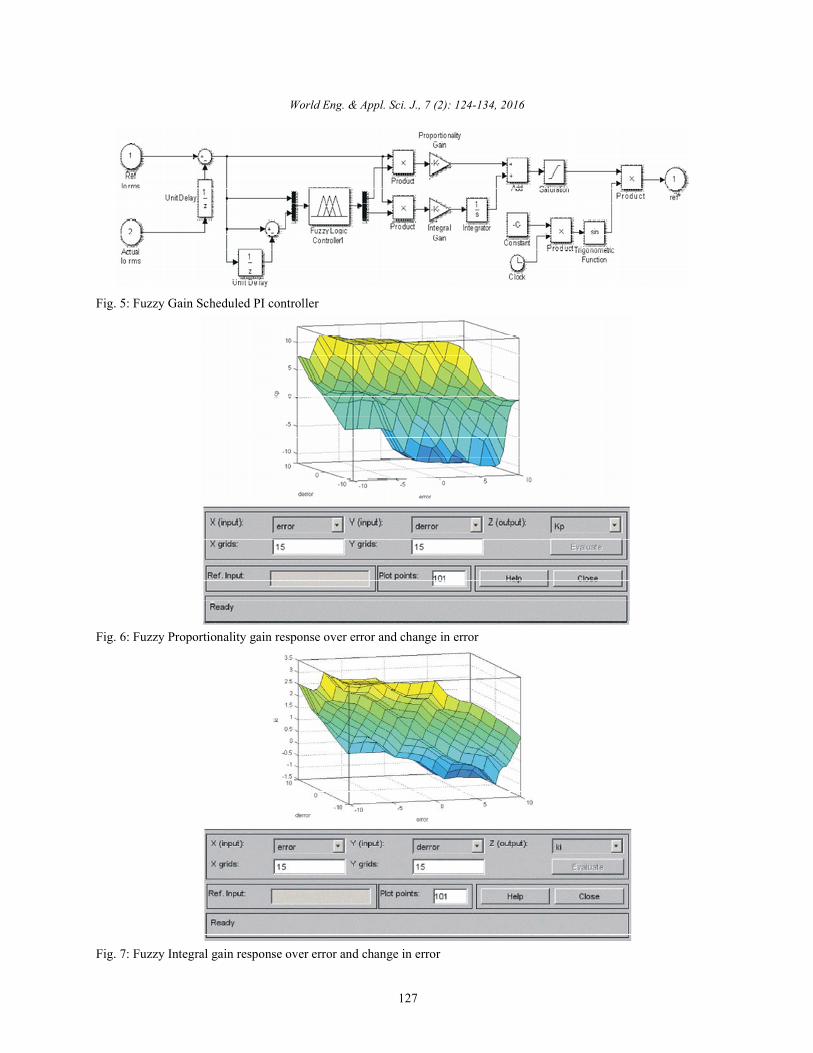
Fig. 5: Fuzzy Gain Scheduled PI controller
Fig. 6: Fuzzy Proportionality gain response over error and change in error
Fig. 7: Fuzzy Integral gain response over error and change in error
World Eng. & Appl. Sci. J., 7 (2): 124-134, 2016
128
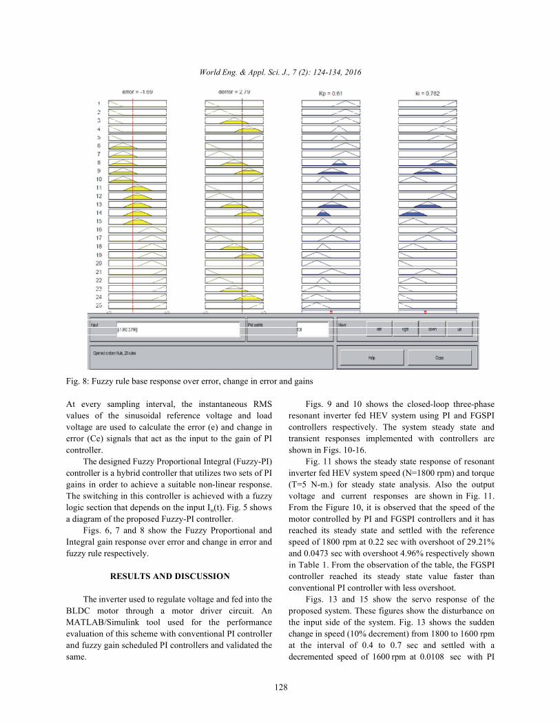
Fig. 8: Fuzzy rule base response over error, change in error and gains
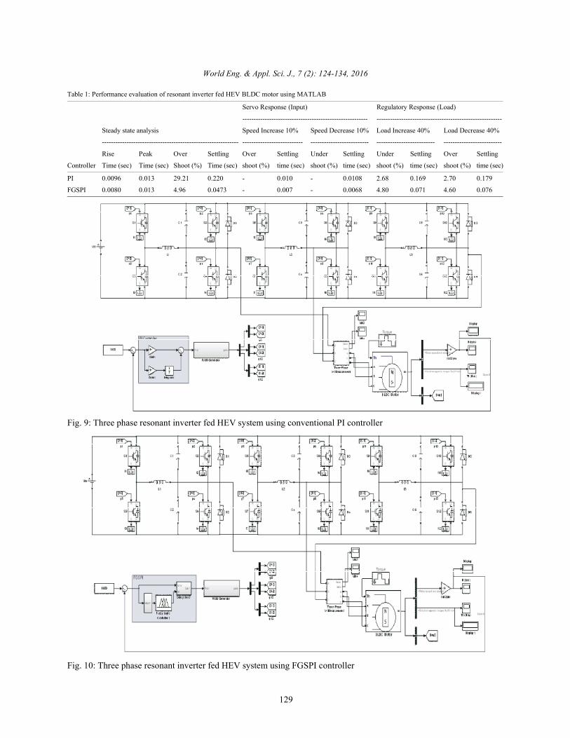
At every sampling interval, the instantaneous RMS Figs. 9 and 10 shows the closed-loop three-phasevalues of the sinusoidal reference voltage and load resonant inverter fed HEV system using PI and FGSPIvoltage are used to calculate the error (e) and change in controllers respectively. The system steady state anderror (Ce) signals that act as the input to the gain of PI transient responses implemented with controllers arecontroller. shown in Figs. 10-16.
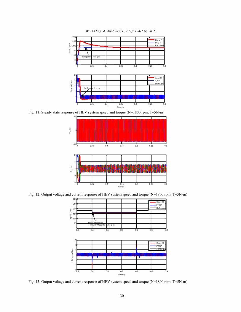
The designed Fuzzy Proportional Integral (Fuzzy-PI) Fig. 11 shows the steady state response of resonantcontroller is a hybrid controller that utilizes two sets of PI inverter fed HEV system speed (N=1800 rpm) and torquegains in order to achieve a suitable non-linear response. (T=5 N-m.) for steady state analysis. Also the outputThe switching in this controller is achieved with a fuzzy voltage and current responses are shown in Fig. 11.logic section that depends on the input I (t). Fig. 5 shows From the Figure 10, it is observed that the speed of thein
a diagram of the proposed Fuzzy-PI controller. motor controlled by PI and FGSPI controllers and it hasFigs. 6, 7 and 8 show the Fuzzy Proportional and reached its steady state and settled with the reference
Integral gain response over error and change in error and speed of 1800 rpm at 0.22 sec with overshoot of 29.21%fuzzy rule respectively. and 0.0473 sec with overshoot 4.96% respectively shown
RESULTS AND DISCUSSION controller reached its steady state value faster than
The inverter used to regulate voltage and fed into the Figs. 13 and 15 show the servo response of theBLDC motor through a motor driver circuit. An proposed system. These figures show the disturbance onMATLAB/Simulink tool used for the performance the input side of the system. Fig. 13 shows the suddenevaluation of this scheme with conventional PI controller change in speed (10% decrement) from 1800 to 1600 rpmand fuzzy gain scheduled PI controllers and validated the at the interval of 0.4 to 0.7 sec and settled with asame. decremented speed of 1600 rpm at 0.0108 sec with PI
in Table 1. From the observation of the table, the FGSPI
conventional PI controller with less overshoot.
World Eng. & Appl. Sci. J., 7 (2): 124-134, 2016
129
Table 1: Performance evaluation of resonant inverter fed HEV BLDC motor using MATLAB
Servo Response (Input) Regulatory Response (Load)
-------------------------------------------------------- --------------------------------------------------------
Steady state analysis Speed Increase 10% Speed Decrease 10% Load Increase 40% Load Decrease 40%
------------------------------------------------------------- --------------------------- -------------------------- -------------------------- --------------------------
Rise Peak Over Settling Over Settling Under Settling Under Settling Over Settling
Controller Time (sec) Time (sec) Shoot (%) Time (sec) shoot (%) time (sec) shoot (%) time (sec) shoot (%) time (sec) shoot (%) time (sec)
PI 0.0096 0.013 29.21 0.220 - 0.010 - 0.0108 2.68 0.169 2.70 0.179
FGSPI 0.0080 0.013 4.96 0.0473 - 0.007 - 0.0068 4.80 0.071 4.60 0.076
Fig. 9: Three phase resonant inverter fed HEV system using conventional PI controller
Fig. 10: Three phase resonant inverter fed HEV system using FGSPI controller
0 0.05 0.1 0.15 0.2 0.25 0.30
500
1000
1500
2000
2500
3000
Spee
d (r
pm)
0 0.05 0.1 0.15 0.2 0.25 0.30
5
10
15
20
25
Time (s)
Torq
ue(N
-m)
Conv PIFGSPIRef speed
Conv PIFGSPIRef torque
Set Speed =1800 rpm
Set Torque=5 N-m
0 0.05 0.1 0.15 0.2 0.25 0.3-500
0
500
Vab
c (V)
0 0.05 0.1 0.15 0.2 0.25 0.3-20
-10
0
10
20
I abc (A
)
Time (s)
0.3 0.4 0.5 0.6 0.7 0.8 0.90
500
1000
1500
2000
2500
3000
Spee
d (r
pm)
0.3 0.4 0.5 0.6 0.7 0.8 0.9-10
-5
0
5
10
15
20
Time (s)
Torq
ue(N
-m)
Conv PIFGSPIRef speed
Conv PIFGSPIRef torque
10%decrement in(From 1800 rpm to 1600 rpm)
World Eng. & Appl. Sci. J., 7 (2): 124-134, 2016
130
Fig. 11: Steady state response of HEV system speed and torque (N=1800 rpm, T=5N-m)
Fig. 12: Output voltage and current response of HEV system speed and torque (N=1800 rpm, T=5N-m)
Fig. 13: Output voltage and current response of HEV system speed and torque (N=1800 rpm, T=5N-m)

0.3 0.4 0.5 0.6 0.7 0.8 0.9-500
0
500
V abc (V
)
0.3 0.4 0.5 0.6 0.7 0.8 0.9-20
-10
0
10
20
I abc (A
)
Time (s)
0.9 1 1.1 1.2 1.3 1.4 1.50
500
1000
1500
2000
2500
3000
Spee
d (r
pm)
0.9 1 1.1 1.2 1.3 1.4 1.5-10
-5
0
5
10
15
20
Time (s)
Tor
que(
N-m
)
Conv PIFGSPIRef speed
Conv PIFGSPIRef torque
10% increment in(From 1800 rpm to 2000 rpm)
0.9 1 1.1 1.2 1.3 1.4 1.5-500
0
500
V abc (V
)
0.9 1 1.1 1.2 1.3 1.4 1.5-20
-10
0
10
20
I abc
(A)
Time (s)
World Eng. & Appl. Sci. J., 7 (2): 124-134, 2016
131
Fig. 14: Voltage and current responses of HEV system for change in speed (up to 0.4sec, N=1800 rpm, T=5N-m; t= 0.4– 0.7sec, N=1600 rpm, T=5N-m; t= 0.7 - 1sec, N=1800 rpm, T=5N-m)
Fig. 15: Speed and torque responses of HEV system for change in speed (N=1800 rpm up to 1 sec, T=5N-m; t= 1 – 1.3sec,N=2000 rpm, T=5N-m; t= 1.3 – 1.5sec, N=1800 rpm, T=5N-m)
Fig. 16: Voltage and current responses of HEV system for change in speed (N=1800 rpm up to 1 sec, T=5N-m; t= 1 –1.3sec, N=2000 rpm, T=5N-m; t= 1.3 – 1.5sec, N=1800 rpm, T=5N-m)
0.3 0 .4 0.5 0 .6 0.7 0 .8 0 .91700
1750
1800
1850
1900
Spee
d (r
pm)
0 .3 0 .4 0.5 0 .6 0.7 0 .8 0 .90
5
10
15
Torq
ue(N
-m)
Time (s)
Conv PIFGSPIRef Troque
Conv PIFGSPIRef Speed
40% increment in(Torque from 5 N-m to 8 N-
0.3 0.4 0.5 0.6 0.7 0.8 0.9-500
0
500
Vab
c (V)
0.3 0.4 0.5 0.6 0.7 0.8 0.9-20
-10
0
10
20
I abc (A
)
Time (s)
0 .9 1 1 .1 1 .2 1 .3 1 .4 1 .51 7 0 0
1 7 5 0
1 8 0 0
1 8 5 0
1 9 0 0
Spee
d (r
pm)
0 .9 1 1 .1 1 .2 1 .3 1 .4 1 .50
5
1 0
1 5
Torq
ue(N
-m)
Time (s)
Co nv P IFGSPIRef T ro qu e
Con v P IFGSPIRef S peed
4 0 % decrement in lo ad(To rq ue fro m 5 N -m to 8 N -m)
World Eng. & Appl. Sci. J., 7 (2): 124-134, 2016
132
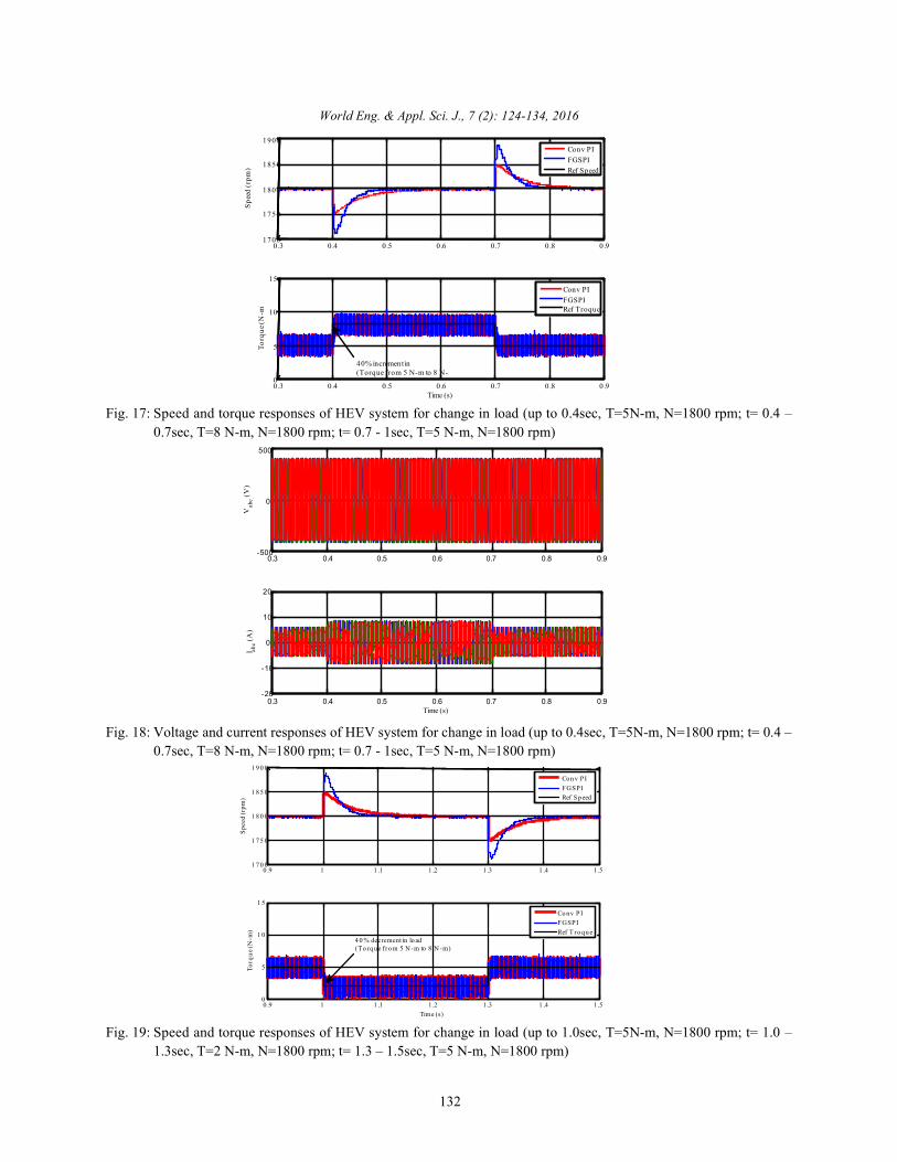
Fig. 17: Speed and torque responses of HEV system for change in load (up to 0.4sec, T=5N-m, N=1800 rpm; t= 0.4 –0.7sec, T=8 N-m, N=1800 rpm; t= 0.7 - 1sec, T=5 N-m, N=1800 rpm)
Fig. 18: Voltage and current responses of HEV system for change in load (up to 0.4sec, T=5N-m, N=1800 rpm; t= 0.4 –0.7sec, T=8 N-m, N=1800 rpm; t= 0.7 - 1sec, T=5 N-m, N=1800 rpm)
Fig. 19: Speed and torque responses of HEV system for change in load (up to 1.0sec, T=5N-m, N=1800 rpm; t= 1.0 –1.3sec, T=2 N-m, N=1800 rpm; t= 1.3 – 1.5sec, T=5 N-m, N=1800 rpm)
0.9 1 1.1 1.2 1.3 1.4 1.5-500
0
500
Vab
c (V)
0.9 1 1.1 1.2 1.3 1.4 1.5-20
-10
0
10
20
I abc (A
)
Time (s)
World Eng. & Appl. Sci. J., 7 (2): 124-134, 2016
133
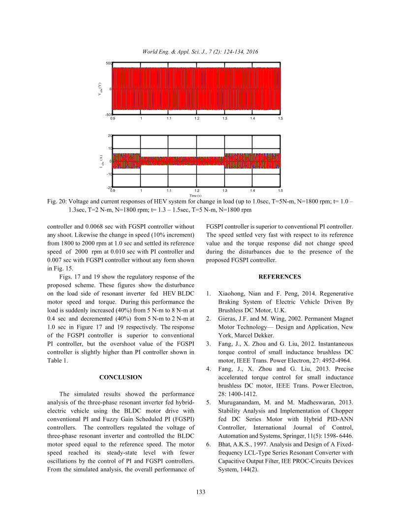
Fig. 20: Voltage and current responses of HEV system for change in load (up to 1.0sec, T=5N-m, N=1800 rpm; t= 1.0 –1.3sec, T=2 N-m, N=1800 rpm; t= 1.3 – 1.5sec, T=5 N-m, N=1800 rpm
controller and 0.0068 sec with FGSPI controller without FGSPI controller is superior to conventional PI controller.any shoot. Likewise the change in speed (10% increment) The speed settled very fast with respect to its referencefrom 1800 to 2000 rpm at 1.0 sec and settled its reference value and the torque response did not change speedspeed of 2000 rpm at 0.010 sec with PI controller and during the disturbances due to the presence of the0.007 sec with FGSPI controller without any form shown proposed FGSPI controller.in Fig. 15.
Figs. 17 and 19 show the regulatory response of the REFERENCESproposed scheme. These figures show the disturbanceon the load side of resonant inverter fed HEV BLDC 1. Xiaohong, Nian and F. Peng, 2014. Regenerativemotor speed and torque. During this performance the Braking System of Electric Vehicle Driven Byload is suddenly increased (40%) from 5 N-m to 8 N-m at Brushless DC Motor, U.K. 0.4 sec and decremented (40%) from 5 N-m to 2 N-m at 2. Gieras, J.F. and M. Wing, 2002. Permanent Magnet1.0 sec in Figure 17 and 19 respectively. The response Motor Technology— Design and Application, Newof the FGSPI controller is superior to conventional York, Marcel Dekker. PI controller, but the overshoot value of the FGSPI 3. Fang, J., X. Zhou and G. Liu, 2012. Instantaneouscontroller is slightly higher than PI controller shown in torque control of small inductance brushless DCTable 1. motor, IEEE Trans. Power Electron, 27: 4952-4964.
CONCLUSION accelerated torque control for small inductance
The simulated results showed the performance 28: 1400-1412. analysis of the three-phase resonant inverter fed hybrid- 5. Muruganandam, M. and M. Madheswaran, 2013.electric vehicle using the BLDC motor drive with Stability Analysis and Implementation of Chopperconventional PI and Fuzzy Gain Scheduled PI (FGSPI) fed DC Series Motor with Hybrid PID-ANNcontrollers. The controllers regulated the voltage of Controller, International Journal of Control,three-phase resonant inverter and controlled the BLDC Automation and Systems, Springer, 11(5): 1598- 6446.motor speed equal to the reference speed. The motor 6. Bhat, A.K.S., 1997. Analysis and Design of A Fixed-speed reached its steady-state level with fewer frequency LCL-Type Series Resonant Converter withoscillations by the control of PI and FGSPI controllers. Capacitive Output Filter, IEE PROC-Circuits DevicesFrom the simulated analysis, the overall performance of System, 144(2).
4. Fang, J., X. Zhou and G. Liu, 2013. Precise
brushless DC motor, IEEE Trans. Power Electron,
World Eng. & Appl. Sci. J., 7 (2): 124-134, 2016
134
7. Raju, G.S.N. and Doradla Seshagirirao, 1995. An LCL 13. Peng, F.Z., Gui-Jua Su and L.M. Tolbert, 2004. AResonant converter with PWM Control Analysis, Passive Soft-Switching Snubber for PWM Inverters,simulation and Implementation, IEEE Transactions on In IEEE Transactions on Power Electronics, 19(2).Power Electronics, 10(2). 14. Jang, G.H., J.H. Park and J.H. Chang, 2002. Position
8. Bhat, A.K.S., 1994. Analysis and Design of LCL- detection and start-up algorithm of a rotor in aType Series Resonant Converter, IEEE INTELEC, sensorless BLDC motor utilizing inductancepp: 172-178. variation, IEE Proc.,Electr. Power Appl., 149: 137-142.
9. Bhat, A.K.S., 1993. Analysis and design of a series 15. Jahns, T.M. Soong and W.L., 1996. Pulsating Torqueparallel resonant converter, IEEE Trans. Power Minimization Techniques for Permanent Magnet ACElectron, 8: 1-11. Motor Drives – a Review, Industrial Electronics, IEEE
10. Mangesh, B., K.V. Borage, M.S. Nagesh Bhatia and Transactions, 43: 321-330. Sunil Tiwari, 2009. Characteristics and Design of an 16. Smith, K.M.and K.M. Smedley, 1997. A ComparisonAsymmetrical Duty-Cycle-Controlled LCL-T of Voltage-Mode Soft-Switching Methods for PWMResonant Converter, IEEE Transactions on Power Converters, In IEEE Trans. Power Electronics,Electronics, 24(10). 12(2): 376-86.
11. Singh, B., 1997. Recent Advances in Permanent 17. Åström, K.J. and T.H. Hägglund, 1995. New tuningMagnet Brushless DC Motors, Sadhana – Academy methods for PID controllers, Proc. of the 3 EuropeanProceedings in Engineering Sciences, 22: 837-853. Control Conf, pp: 2456-62.
12. Mohan, N., T.M. Undeland and W.P. Robbins, 2003.Power Electronics: Converters, Applications andDesign, 3 , John Wiley & Sons, New York.rd
rd


![Performance Analysis of PI and Fuzzy Control for Modified ... · There are various types of resonant converters [2] [3]. Among these, series -parallel resonant converter (SPRC) is](https://img.pdfslide.us/doc/110x75/5eb95ccf856d28309c62a4f2/performance-analysis-of-pi-and-fuzzy-control-for-modified-there-are-various.jpg)