Embed Size (px)
Citation preview
Use of FTDI devices in life support and/or safety applications is entirely at the user’s risk, and the user
agrees to defend, indemnify and hold harmless FTDI from any and all damages, claims, suits or expense
resulting from such
Future Technology Devices International Limited (FTDI)
Unit 1, 2 Seaward Place, Glasgow G41 1HH, United Kingdom Tel.: +44 (0) 141 429 2777 Fax: + 44 (0) 141 429 2758
E-Mail (Support): [email protected] Web: http://www.ftdichip.com
Copyright © 2012 Future Technology Devices International Limited
Future Technology Devices International Ltd.
Application Note
AN_173 Establishing FT1248
Communications using a Morph-IC-II
Document Reference No.: FT_000429
Version 1.1
Issue Date: 2012-06-26
The Morph-IC-II module is an FPGA-USB development platform that can be programmed to support a number of serial communications interfaces including FT1248 and Synchronous 245 FIFO. A number of supporting source code samples have been provided by FTDI to assist in the development of Morph-IC-II applications. One of these is an FT1248 application. This application note contains
the HDL to synthesise the Master FT1248 and two terminals used to control the
hardware and transfer data.
This application note gives a step-by-step guide in how to establish an FT1248 demonstration application.

Copyright © 2012 Future Technology Devices International Limited 1
Document Reference No.: FT_000429 AN_173 Establishing FT1248 Communications using a Morph-IC-II
Version 1.1 Clearance No.: FTDI# 220
Table of Contents
1 Introduction .................................................................... 2
1.1 What is a UM232H Module? ....................................................... 2
1.2 What is Morph-IC-II? ................................................................ 3
1.3 What is Synchronous 245 FIFO? ............................................... 3
1.4 What is FT1248? ....................................................................... 3
2 Interfaces used in this Application .................................. 4
2.1 FT1248 Signal Flow ................................................................... 4
2.2 Syncronous 245 FIFO Signal Flow ............................................. 4
3 Example FT1248 FIFO Application ................................... 5
3.1 An Outline of the FT1248 Application ........................................ 5
3.2 RTL Code ................................................................................... 6
3.3 Reset Polarity ........................................................................... 7
4 Example Application Procedure ....................................... 8
4.1 Configuring the EEPROM of the UM232H ................................... 8
4.2 Connecting the Morph-IC-II and UM232H ................................. 9
4.3 Editing the Quartus Project ..................................................... 11
4.4 Load RBF ................................................................................. 11
4.5 Test for communications ......................................................... 12
4.5.1 Verification Procedure .............................................................................. 13
5 Summary ....................................................................... 17
6 Contact Information ...................................................... 18
Appendix A – Abbreviations ............................................... 19
Appendix B – References ................................................... 20
Appendix C – Revision History ........................................... 21
Copyright © 2012 Future Technology Devices International Limited 2
Document Reference No.: FT_000429 AN_173 Establishing FT1248 Communications using a Morph-IC-II
Version 1.1 Clearance No.: FTDI# 220
1 Introduction
The “MorphIC_FT1248_master” zip-file gives an example FT1248 application with example software to
control the interface. This application contains the necessary HDL source files to establish two interfaces: an FT1248 communications interface between an FTDI UM232H and the FPGA of an FTDI Morph-IC-II, as well as a Synchronous 245 FIFO interface between the FPGA and FT2232H of the Morph-IC-II.
The aim of this application note is to give a guide to evaluating the FT1248 interface.
The application source code can be downloaded from http://www.ftdichip.com/Products/Files/MorphIC_FT1248_master.zip
The following apparatus is used in this application example:
1 x FTDI Morph-IC-II – A USB-FPGA development module
1 x FTDI UM232H – A Hi-Speed USB to Serial/FIFO Module
A proto-typing setup used to connect the UM232H to the Morph-IC-II
1x USB Type-A cable and 1 x USB Type-B cable
FT1248 application project files – The HDL collateral supplied for this application
FT_Prog – A Programming Utility for FTDI devices
MorphLd-II – Programming utility for the Morph-IC-II (included in download)
Quartus-II – An Altera HDL Tool-Chain for use with Altera FPGAs
FT1248 Controller – An FTDI utility used from controlling FT1248 data transfers (included in download)
Terminal.x – An FTDI utility for transferring data over different interfaces (included in download)
See Appendix B for links.
On completion of reading this app note the reader should be able to:
Configure a FT2232H device for synchronous 245 FIFO mode
Configure a FT232H device for synchronous FT1248 mode
Program an Altera based FPGA to bridge an FT1248 device to a synchronous 245 FIFO device
1.1 What is a UM232H Module?
A UM232H is the evaluation board for the FT232H. This module provides access to the serial/FIFO data channel. This module may be used to convert one USB port to either: UART, Synchronous 245 FIFO, Asynchronous 245 FIFO, FT1248, JTAG, I2C and SPI.
For more information on the modules please see:
UM232H
http://www.ftdichip.com/Support/Documents/DataSheets/Modules/DS_UM232H.pdf
FT232H Datasheet
http://www.ftdichip.com/Support/Documents/DataSheets/ICs/DS_FT232H.pdf
Copyright © 2012 Future Technology Devices International Limited 3
Document Reference No.: FT_000429 AN_173 Establishing FT1248 Communications using a Morph-IC-II
Version 1.1 Clearance No.: FTDI# 220
1.2 What is Morph-IC-II?
Morph-IC-II is a USB-FPGA development platform. The major components of this module are the FT2232H and an Altera Cyclone II FPGA.
The FT2232H is a USB communications device which converts USB data into a range of different interfaces including UART, Synchronous 245 FIFO, Asynchronous 245 FIFO and more. The FT2232H
provides one programing channel for the FPGA (passive serial) and one application data channel to access data after configuration of the FPGA. Passive serial is an interface widely used by Altera FPGAs for programming and configuration. This interface is supported by the FT2232H’s MPSSE (Multi-Protocol Synchronous Serial Engine).
For additional information please refer to the following documentation:
Morph-IC-II Datasheet
http://www.ftdichip.com/Support/Documents/DataSheets/Modules/DS_Morph-IC-II.pdf
MorphLd and MorphIO-II Utilities for Morph-IC-II
http://www.ftdichip.com/Support/Documents/AppNotes/AN_141_MorphIO-II%20and%20MorphLd%20Utilities%20for%20Morph-IC-II.pdf
1.3 What is Synchronous 245 FIFO?
Synchronous 245 FIFO is a half-duplex point-to-point communications interface. This interface is synchronised to transmit data at 60MHz. Synchronous 245 FIFO contains all the signals used by Asynchronous 245 FIFO plus an additional 2 lines: clock out which is a 60MHz clock signal and output
enable used to enable the data bus outputs of a slave device.
Synchronous FIFO can transfer data at much higher data rates than Asynchronous FIFO. Synchronous 245 FIFO requires the master and the slave devices to be synchronised to the same 60MHz clock. Using
this application note and the supporting hardware and application files, establishing a successful Synchronous 245 communication link can be made easy.
For additional information please see:
AN_130 FT2232H Used In An FT245 Style Synchronous FIFO Mode
http://www.ftdichip.com/Support/Documents/AppNotes/AN_130_FT2232H_Used_In_FT245%20Synchronous%20FIFO%20Mode.pdf
DS_FT2232H
http://www.ftdichip.com/Support/Documents/DataSheets/Modules/DS_FT2232H_Mini_Module.pdf
AN_165_Establishing_Synchronous_245_FIFO_Communications_using_a_Morph-IC-II
1.4 What is FT1248?
FT1248 is a synchronous half duplex interface pioneered by FTDI. FT1248 is a similar interface to SPI,
but with eight data lines labelled MIOSIO 0 to 7. These lines can be used to transfer parallel data in both directions. The MISO line can be designated to be used for indicating the status of the slave in parallel with the data being transferred.
FT1248 can be configured to operate in different modes, the clock polarity, number of parallel bits transferred, the serial bit order and flow control can be varied. Varying the number of parallel bits being transferred or bus width, changes the maximum rate of data transfer. The bus width modes are 1-bit wide mode, 2-bit wide mode, 4-bit wide mode and 8-bit wide mode. 1-bit wide mode uses only one of the
MIOSIO data line to transfer data. 2-bit wide mode, 4-bit wide mode and 8-bit wide mode used 2, 4 and
8 MIOSIO data lines respectively to transfer data in parallel.
The FT232H contains a slave FT1248 to USB interface that can be selected for use by an external EEPROM. This interface requires an input clock signal sourced from a master device, the frequency of the clock can be up to 30MHz.
Copyright © 2012 Future Technology Devices International Limited 4
Document Reference No.: FT_000429 AN_173 Establishing FT1248 Communications using a Morph-IC-II
Version 1.1 Clearance No.: FTDI# 220
2 Interfaces used in this Application
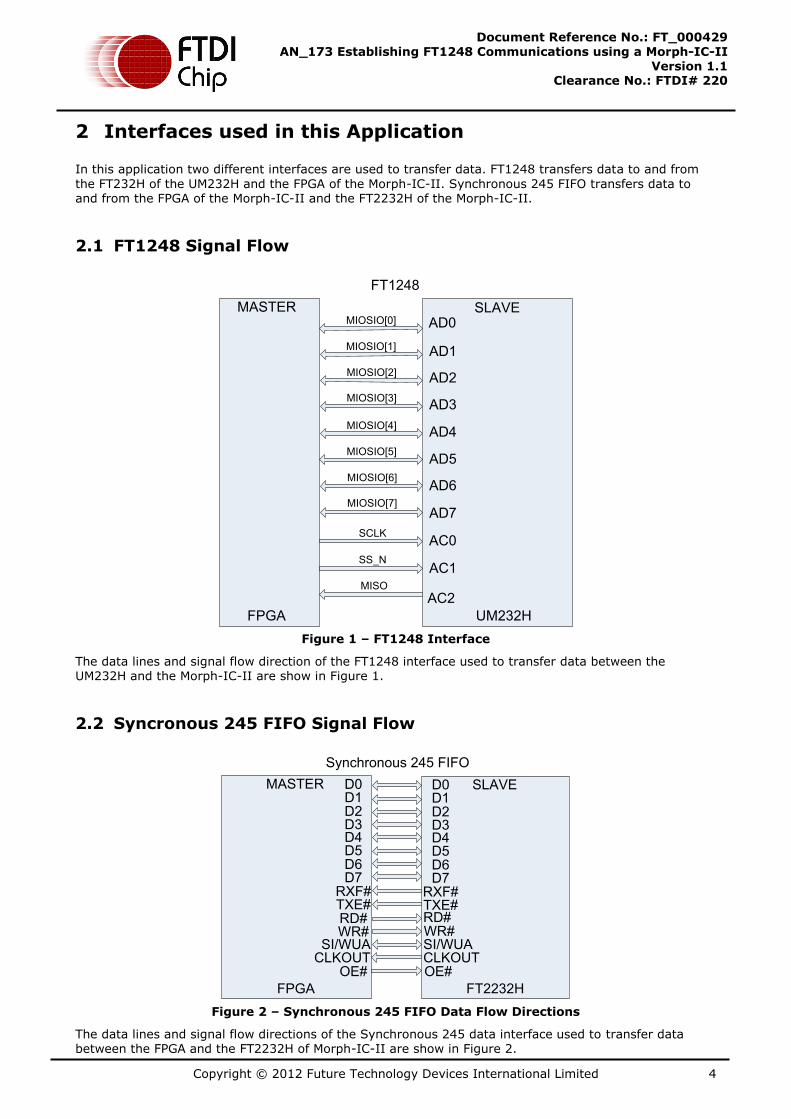
In this application two different interfaces are used to transfer data. FT1248 transfers data to and from
the FT232H of the UM232H and the FPGA of the Morph-IC-II. Synchronous 245 FIFO transfers data to and from the FPGA of the Morph-IC-II and the FT2232H of the Morph-IC-II.
2.1 FT1248 Signal Flow
AD0
AD1
AD2
AD3
AD4
AD5
AD6
AD7
AC0
AC1
AC2
MASTER SLAVE
FT1248
FPGA UM232H
MIOSIO[0]
MIOSIO[1]
MIOSIO[2]
MIOSIO[3]
MIOSIO[4]
MIOSIO[5]
MIOSIO[6]
MIOSIO[7]
SCLK
SS_N
MISO
Figure 1 – FT1248 Interface
The data lines and signal flow direction of the FT1248 interface used to transfer data between the UM232H and the Morph-IC-II are show in Figure 1.
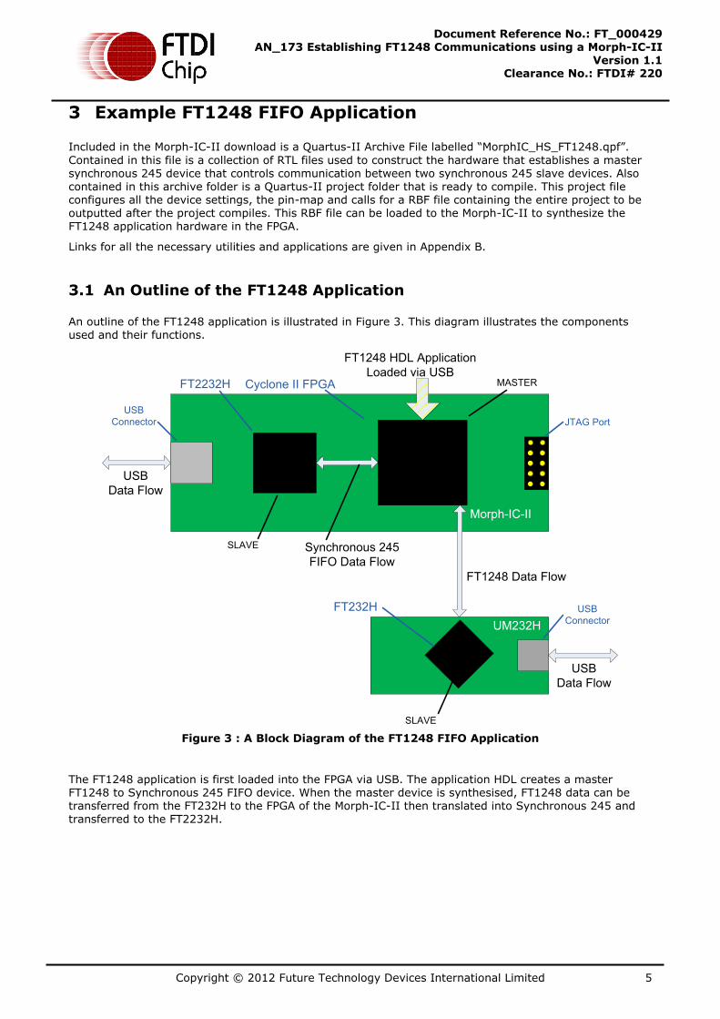
2.2 Syncronous 245 FIFO Signal Flow
D0D1D2D3D4D5D6D7
RXF#TXE#RD#WR#
SI/WUACLKOUT
OE#
D0D1D2D3D4D5D6D7
RXF#TXE#RD#WR#SI/WUACLKOUTOE#
MASTER SLAVE
Synchronous 245 FIFO
FPGA FT2232H
Figure 2 – Synchronous 245 FIFO Data Flow Directions
The data lines and signal flow directions of the Synchronous 245 data interface used to transfer data between the FPGA and the FT2232H of Morph-IC-II are show in Figure 2.
Copyright © 2012 Future Technology Devices International Limited 5
Document Reference No.: FT_000429 AN_173 Establishing FT1248 Communications using a Morph-IC-II
Version 1.1 Clearance No.: FTDI# 220
3 Example FT1248 FIFO Application
Included in the Morph-IC-II download is a Quartus-II Archive File labelled “MorphIC_HS_FT1248.qpf”.
Contained in this file is a collection of RTL files used to construct the hardware that establishes a master synchronous 245 device that controls communication between two synchronous 245 slave devices. Also contained in this archive folder is a Quartus-II project folder that is ready to compile. This project file configures all the device settings, the pin-map and calls for a RBF file containing the entire project to be outputted after the project compiles. This RBF file can be loaded to the Morph-IC-II to synthesize the FT1248 application hardware in the FPGA.
Links for all the necessary utilities and applications are given in Appendix B.
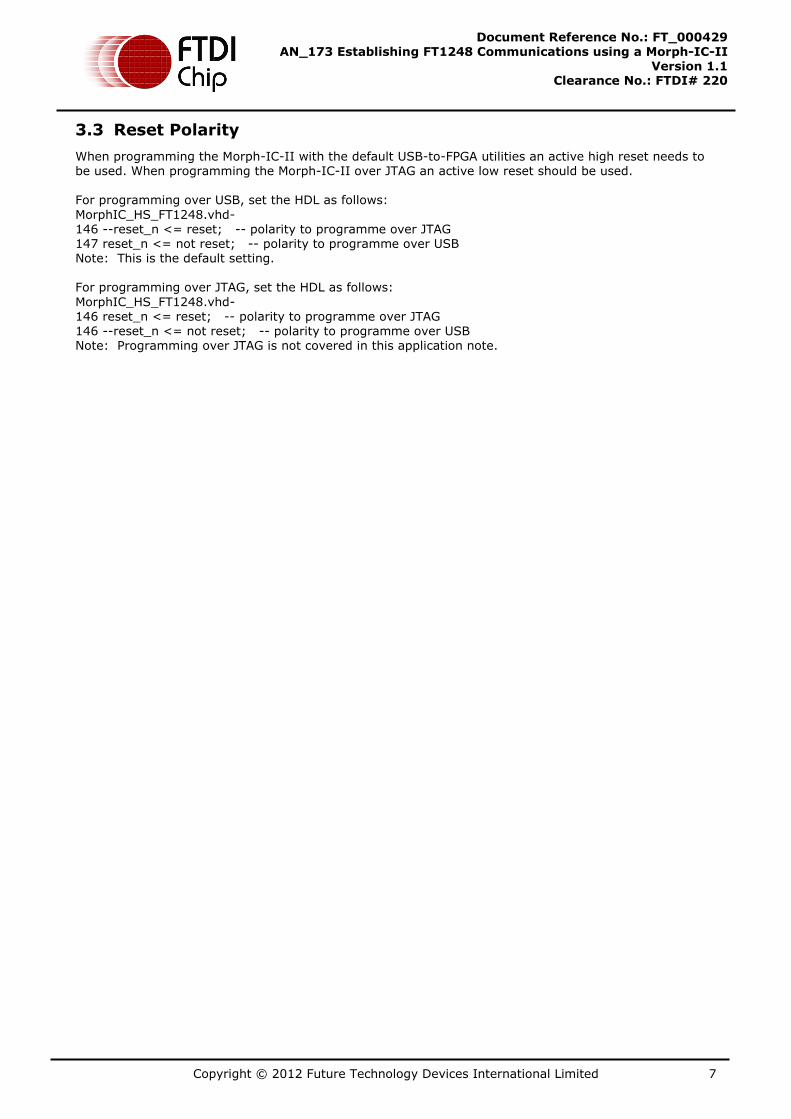
3.1 An Outline of the FT1248 Application
An outline of the FT1248 application is illustrated in Figure 3. This diagram illustrates the components used and their functions.
SLAVE
SLAVE
MASTER
Morph-IC-II
UM232H
Synchronous 245
FIFO Data Flow
USB
Data Flow
USB
Data Flow
FT1248 HDL Application
Loaded via USBFT2232H
FT232H
Cyclone II FPGA
JTAG Port
USB
Connector
USB
Connector
FT1248 Data Flow
Figure 3 : A Block Diagram of the FT1248 FIFO Application
The FT1248 application is first loaded into the FPGA via USB. The application HDL creates a master FT1248 to Synchronous 245 FIFO device. When the master device is synthesised, FT1248 data can be transferred from the FT232H to the FPGA of the Morph-IC-II then translated into Synchronous 245 and transferred to the FT2232H.

Copyright © 2012 Future Technology Devices International Limited 6
Document Reference No.: FT_000429 AN_173 Establishing FT1248 Communications using a Morph-IC-II
Version 1.1 Clearance No.: FTDI# 220
3.2 RTL Code
The following code sample lists the ports of the Synchronous 245 Interface application which is available in the “MorphIC_FT1248_master” download. These ports include a reset line, the synchronous 245 FIFO data interface of the on board FT2232H of the Morph-IC-II and an FT1248 data interface of UM232H. ENTITY MorphIC_HS_FT1248 IS
PORT (-- Inputs
clk50 : in std_logic; -- 50MHz clock input unused
reset : in std_logic; -- Active low reset via BD7
-- Morphic on board FT2232H signals
mdata : inout std_logic_vector(7 downto 0); -- Port A Data Bus
mrxfn : in std_logic;
mtxen : in std_logic;
mrdn : out std_logic;
mwrn : out std_logic;
-- moen : out std_logic;
-- old_clock : in std_logic; -- unused
msndimm : out std_logic; -- unused
-- mclk60 : in std_logic;
-- High speed Synchronous 245 signals
acbus9 : in std_logic; -- unused
acbus8 : in std_logic; -- unused
acbus6 : in std_logic; -- unused
acbus5 : in std_logic; -- unused
acbus4 : in std_logic; -- unused
acbus3 : in std_logic; -- unused
hdata : inout std_logic_vector(7 downto 0);
sclk : out std_logic; -- SCLK
ss_n : out std_logic; -- select #
miso : in std_logic -- miso
);
END MorphIC_HS_FT1248;
The following VHDL files are included in the Quartus-II project for this application:
FT1248_master.vhd
- Used to access FT232H chip via the FT1248 bus
upcntg.vhd
- A generic n bit up counter with async and sync resets.
syncflop.vhd
- This syncs signals from different clock domain
MorphIC_HS_FT1248.vhd
- FT1248 master interface between FT232H and FT2232H device
FT1248_master_cont_cont.vhd
- This will control the FT1248_master block by decoding a wrapper
from the host PC.
dncntlg.vhd
- This is a generic n bit down counter with async and sync resets
and load
The name of the Quartus-II project is MorphIC_HS_FT1248.qpf
Copyright © 2012 Future Technology Devices International Limited 7
Document Reference No.: FT_000429 AN_173 Establishing FT1248 Communications using a Morph-IC-II
Version 1.1 Clearance No.: FTDI# 220
3.3 Reset Polarity
When programming the Morph-IC-II with the default USB-to-FPGA utilities an active high reset needs to be used. When programming the Morph-IC-II over JTAG an active low reset should be used. For programming over USB, set the HDL as follows:
MorphIC_HS_FT1248.vhd- 146 --reset_n <= reset; -- polarity to programme over JTAG 147 reset_n <= not reset; -- polarity to programme over USB Note: This is the default setting. For programming over JTAG, set the HDL as follows:
MorphIC_HS_FT1248.vhd- 146 reset_n <= reset; -- polarity to programme over JTAG
146 --reset_n <= not reset; -- polarity to programme over USB Note: Programming over JTAG is not covered in this application note.

Copyright © 2012 Future Technology Devices International Limited 8
Document Reference No.: FT_000429 AN_173 Establishing FT1248 Communications using a Morph-IC-II
Version 1.1 Clearance No.: FTDI# 220
4 Example Application Procedure
In this section a step by step guide is given for establishing FT1248 communications between a Morph-
IC-II and a UM232H. This guide covers the following processes:
- Configuring the EEPROM of the UM232H
- Connecting the Mini-Module to the Morph-IC-II
- Compiling the Quartus-II project and editing the Pin-Map of the application
- Loading the application to the FPGA
- Verification of FT1248 communications
4.1 Configuring the EEPROM of the UM232H
The EEPROM of the UM232H is set to UART mode by default. To establish FT1248 communications the Serial/FIFO port needs to be configured into FT1248 mode by setting the parameters as shown in bold in the table below. The default EEPROM configuration of the FT2232H on the Morph-IC-II is suitable for this FT1248 application.
It is important to note the FT1248 settings defined by the EEPROM must match the application. There are three options, Clock Polarity High, Bit Order LSB and Flow Ctrl not selected.
Parameter Value Notes
USB Vendor ID (VID) 0403h FTDI default VID (hex)
USB Product UD (PID) 6014h FTDI default PID (hex)
bcd Device 009h
Pull down I/O Pins in USB Suspend
Disabled Enabling this option will make the device pull down on the UART interface lines when in USB suspend mode (PWREN# is high).
Manufacturer Name FTDI
Max Bus Power Current 150mA
Power Source Bus Powered
Device Type FT232H
USB Version 0200 Returns USB 2.0 device description to the host.
Note: The device is a USB 2.0 Full Speed device (12Mb/s) as opposed to a USB 2.0 Hi-Speed device (480Mb/s).
Remote Wake Up Enabled Taking RI# low will wake up the USB host controller from suspend in approximately 20 ms.
High Current I/Os Disabled Enables the high drive level on the UART and ACBUS I/O pins.
Load VCP Driver Enabled Makes the device load the VCP driver interface for the device.
Hardware Specific
Port A
FT1248 Mode Select FT1248 mode to communicate in FT1248 signals through Port A.
Driver D2XX Direct Suppresses VCP driver
FT1248 Options:
CPOL High
Bit Order LSB
Flow Ctrl
Must Match
FT1248 Controller
FT1248 Options define: clock polarity, bit order and flow control. This EEPROM configuration must match the configuration set in the FT1248 Controller before the ports are opened to allow for communications.
Table 1 – Recommended EEPROM Configuration
For a detailed guide in how to program the EEPROM:

Copyright © 2012 Future Technology Devices International Limited 9
Document Reference No.: FT_000429 AN_173 Establishing FT1248 Communications using a Morph-IC-II
Version 1.1 Clearance No.: FTDI# 220
FT_PROG User Guide:
http://www.ftdichip.com/Support/Documents/AppNotes/AN_124_User_Guide_For_FT_PROG.pdf
4.2 Connecting the Morph-IC-II and UM232H
In order to establish communications between a UM232H and a Morph-IC-II, both devices need to be
correctly connected to each other as shown in Figure 4 where the pin labels and pin designators of each connected pin are given. The pins of the Morph-IC-II can be relocated since they are all general purpose I/O pins, the Morph-IC-II pin locations illustrated here are chosen to be in a simple location and they all correlate with the pin-map in the Quartus-II project supplied for this application.
It should be noted that in the UM232H VBUS is connected to VCC to power the chip and V3V3 is
connected to VIO to allow the IOs of the FT232H can be powered; these connections are illustrated in
Figure 4.
MIOSIO[0]
MIOSIO[1]
MIOSIO[2]
MIOSIO[3]
MIOSIO[4]
MIOSIO[5]
MIOSIO[6]
MIOSIO[7]
SCLK
SS_N
MISO
unused
unused
CN
2-7
E1
D3
F3
P2
P1
M4
N1
M2
M1
L2
J4
L1
16
17
18
19
21
22
23
24
26
27
28
29
30
IOD13
Morph-IC-II to UM232H Connections
unusedJ232
unusedK233
Morph-IC-II UM232H
J4-2
J4-4
J4-6
J4-8
J4-10
J4-12
J4-14
J4-16
J4-19
J4-17
J4-15
J4-13
J4-11
J4-9
J4-7
J2-7
J2-8
J2-9
J2-10
J2-11
J2-12
J2-13
J2-14
J1-14
J1-13
J1-12
J1-11
J1-10
J1-9
J1-8
IOD14
IOG13
IOC14
IOG16
IOA12
IOA13
IOA14
IOE14
IOD15
IOB14
IOB13
IOB12
IOJ12
IOJ11
J1-3
J1-2
J2-3
J2-2
V3V3
VIO
5V0
USB
GND GND
Master Slave
Figure 4 – Morph-IC-II and FT232H wire scheme

Copyright © 2012 Future Technology Devices International Limited 10
Document Reference No.: FT_000429 AN_173 Establishing FT1248 Communications using a Morph-IC-II
Version 1.1 Clearance No.: FTDI# 220
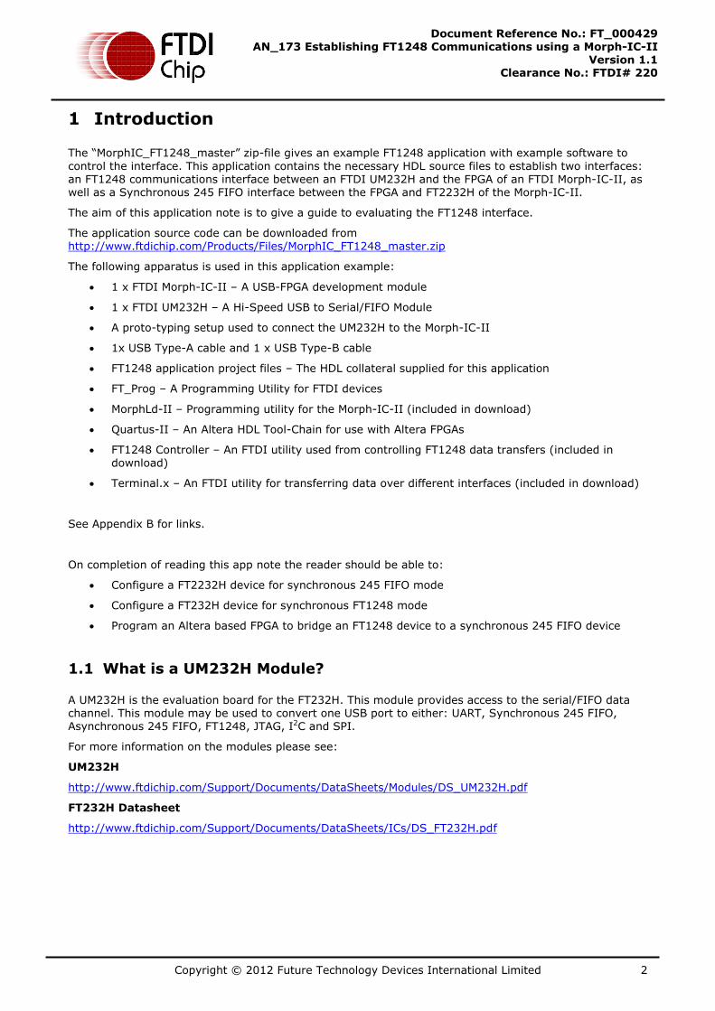
The basic wire configuration of the Morph-IC-II is illustrated in Figure 4. The connections for the FT2232H and the FPGA are shown in Figure 5. These connections are defined by the Morph-IC-II PCB and cannot be changed for this application.
AD0
AD1
AD2
AD3
AD4
AD5
AD6
AD7
RXF#
TXE#
RD#
WR#
SI/WUB
E2
E1
D3
F3
P2
P1
M4
N1
M2
M1
L2
J4
L1
16
17
18
19
21
22
23
24
26
27
28
29
30
IO
IO
IO
IO
IO
IO
IO
IO
IO
IO
IO
IO
IO
Communications Interface
CLKOUTJ232
IO
OE#K233
IO
FT2232HQ
USB
INTERFACE
ALTERA CYCLONE II
EP2C5F256C8N
FPGA
16
17
18
19
21
22
23
24
26
27
28
29
30
32
33
E2
E1
D3
F3
P2
P1
N2
N1
M2
M1
L2
J4
L1
J2
K2
Morph-IC-II
Slave Master
Figure 5 – Communications between the Hi-Speed USB Device
of the Morph-IC-II and the FPGA of the Morph-IC-II
Copyright © 2012 Future Technology Devices International Limited 11
Document Reference No.: FT_000429 AN_173 Establishing FT1248 Communications using a Morph-IC-II
Version 1.1 Clearance No.: FTDI# 220
4.3 Editing the Quartus Project
The FT1248 application contains a Quartus II archive file containing all the source code and compiling parameters. A pre-compiled RBF is also included thus the Quartus II software package is not required for this project, however if any editing is required, the archived project file can be opened and edited using Quartus II.
For Quartus II download and support, please refer to www.altera.com
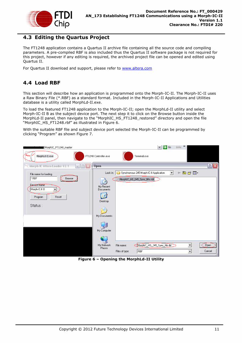
4.4 Load RBF
This section will describe how an application is programmed onto the Morph-IC-II. The Morph-IC-II uses
a Raw Binary File (*.RBF) as a standard format. Included in the Morph-IC-II Applications and Utilities
database is a utility called MorphLd-II.exe.
To load the featured FT1248 application to the Morph-IC-II; open the MorphLd-II utility and select Morph-IC-II B as the subject device port. The next step it to click on the Browse button inside the MorphLd-II panel, then navigate to the “MorphIC_HS_FT1248_restored” directory and open the file “MorphIC_HS_FT1248.rbf” as illustrated in Figure 6.
With the suitable RBF file and subject device port selected the Morph-IC-II can be programmed by clicking “Program” as shown Figure 7.
Figure 6 – Opening the MorphLd-II Utility

Copyright © 2012 Future Technology Devices International Limited 12
Document Reference No.: FT_000429 AN_173 Establishing FT1248 Communications using a Morph-IC-II
Version 1.1 Clearance No.: FTDI# 220
Figure 7 – Program the Morph-IC-II
4.5 Test for communications
FT1248 can be configured in a number of different ways, the clock polarity, bus width, bit-order and flow control can change. The utility FT1248 Controller which is used to control communication between the FT1248 and Morph-IC-II can be configured to communicate in all FT1248 formats; however this program does not configure the EEPROM. Noting this, it is important that the FT1248 Controller’s settings match the FT1248 options set in the EEPROM. The FT1248 Controller is shown in Figure 8. The FT1248 options are as follows: CPOL defines the clock polarity, Bus Width defines the number of parallel bits being
transferred, BORD defines the bit order where 0 sets the MSB to be first, FCTRL determines if flow control is enabled or disabled.
N.B. To avoid the FT1248 from becoming non-responsive, the correct configuration needs to be selected before the Morph-IC-II A port is opened. It the procedure is not followed correctly the utility may halt, if this happens: reset the Morph-IC-II, reprogram the Morph-IC-II and restart the verification.
Figure 8 – FT1248 Controller

Copyright © 2012 Future Technology Devices International Limited 13
Document Reference No.: FT_000429 AN_173 Establishing FT1248 Communications using a Morph-IC-II
Version 1.1 Clearance No.: FTDI# 220
4.5.1 Verification Procedure
Two utilities are supplied as part of the FT1248 application download; these utilities are used to control and monitor FT1248 communications between the UM232H and Morph-IC-II. The utility “FT1248 Controller” is used to display and control data transferred via the Morph-IC-II port A and the utility “terminal.exe” is used to display and control data transferred via the UM232H port. The icons for these utilities are illustrated in Figure 9.
Figure 9 – Verification Utilities
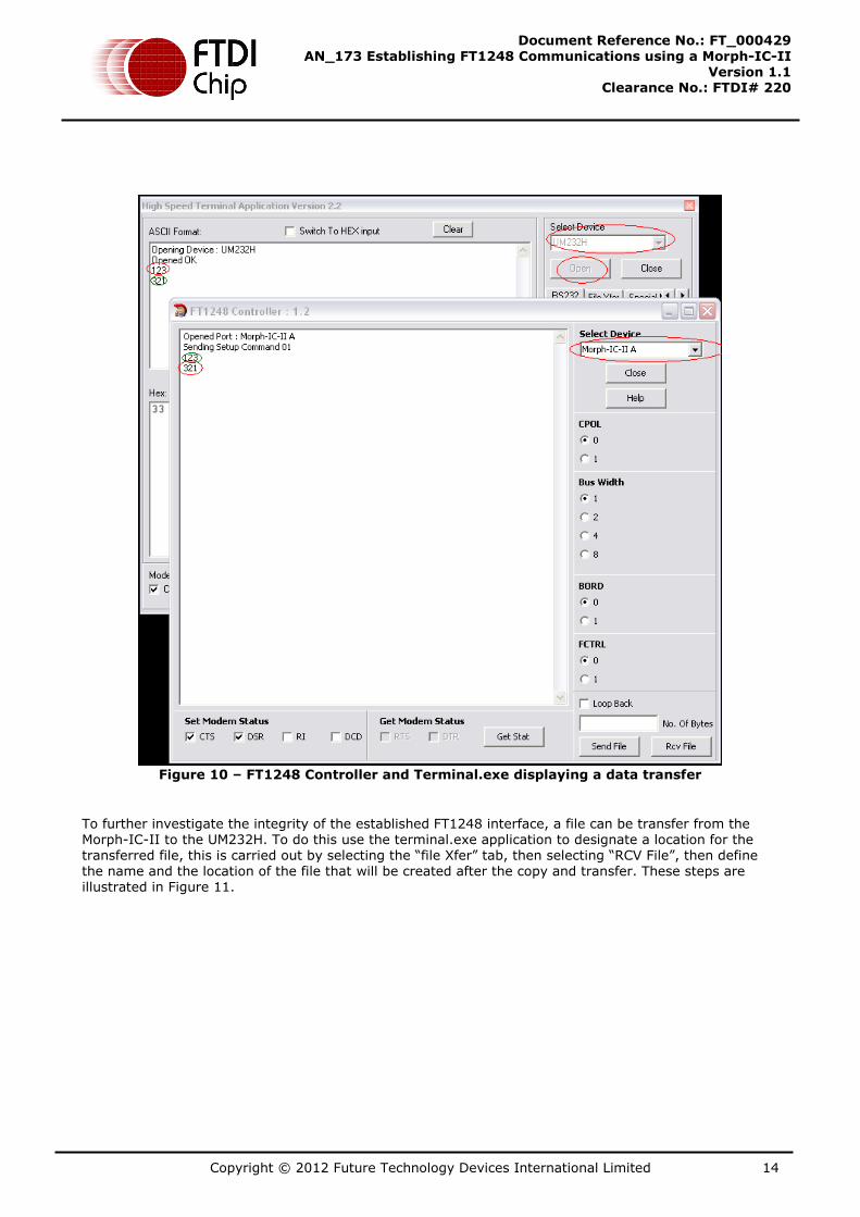
After opening the two utilities, select the FT1248 mode in the FT1248 controller, then select the device each utility should control. The Terminal.exe utility opens the UM232H and the FT1248 Controller opens Channel A of the Morph-IC-II. Select the device port in accordance with the utility and click open as shown in Figure 10.
To carry out a quick communications test, type a few letters in the test tab and press return, if the EEPROM configuration, the wiring and loaded RBF are all correct for this application, the typed string will
(if the setup is correct) transfer and be displayed on the text tab of the other utility. Illustarted in Figure 10, the strings “123” and “321” have been transferred from the UM232H to the Morph-IC-II and Morph-IC-II to the UM232H respectively using FT1248.
Copyright © 2012 Future Technology Devices International Limited 14
Document Reference No.: FT_000429 AN_173 Establishing FT1248 Communications using a Morph-IC-II
Version 1.1 Clearance No.: FTDI# 220
Figure 10 – FT1248 Controller and Terminal.exe displaying a data transfer
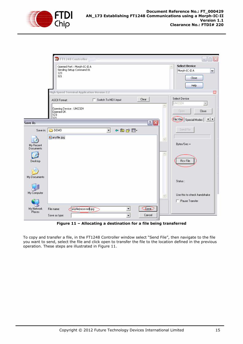
To further investigate the integrity of the established FT1248 interface, a file can be transfer from the Morph-IC-II to the UM232H. To do this use the terminal.exe application to designate a location for the transferred file, this is carried out by selecting the “file Xfer” tab, then selecting “RCV File”, then define the name and the location of the file that will be created after the copy and transfer. These steps are illustrated in Figure 11.
Copyright © 2012 Future Technology Devices International Limited 15
Document Reference No.: FT_000429 AN_173 Establishing FT1248 Communications using a Morph-IC-II
Version 1.1 Clearance No.: FTDI# 220
Figure 11 – Allocating a destination for a file being transferred
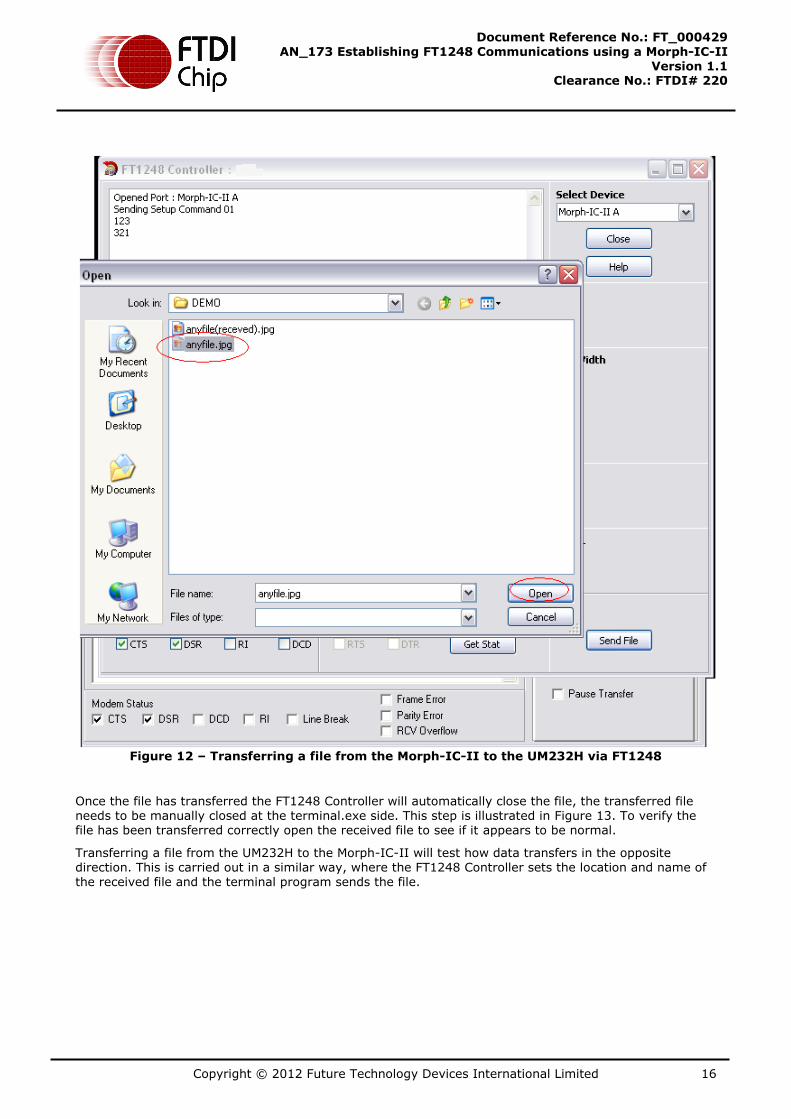
To copy and transfer a file, in the FT1248 Controller window select “Send File”, then navigate to the file you want to send, select the file and click open to transfer the file to the location defined in the previous operation. These steps are illustrated in Figure 11.
Copyright © 2012 Future Technology Devices International Limited 16
Document Reference No.: FT_000429 AN_173 Establishing FT1248 Communications using a Morph-IC-II
Version 1.1 Clearance No.: FTDI# 220
Figure 12 – Transferring a file from the Morph-IC-II to the UM232H via FT1248
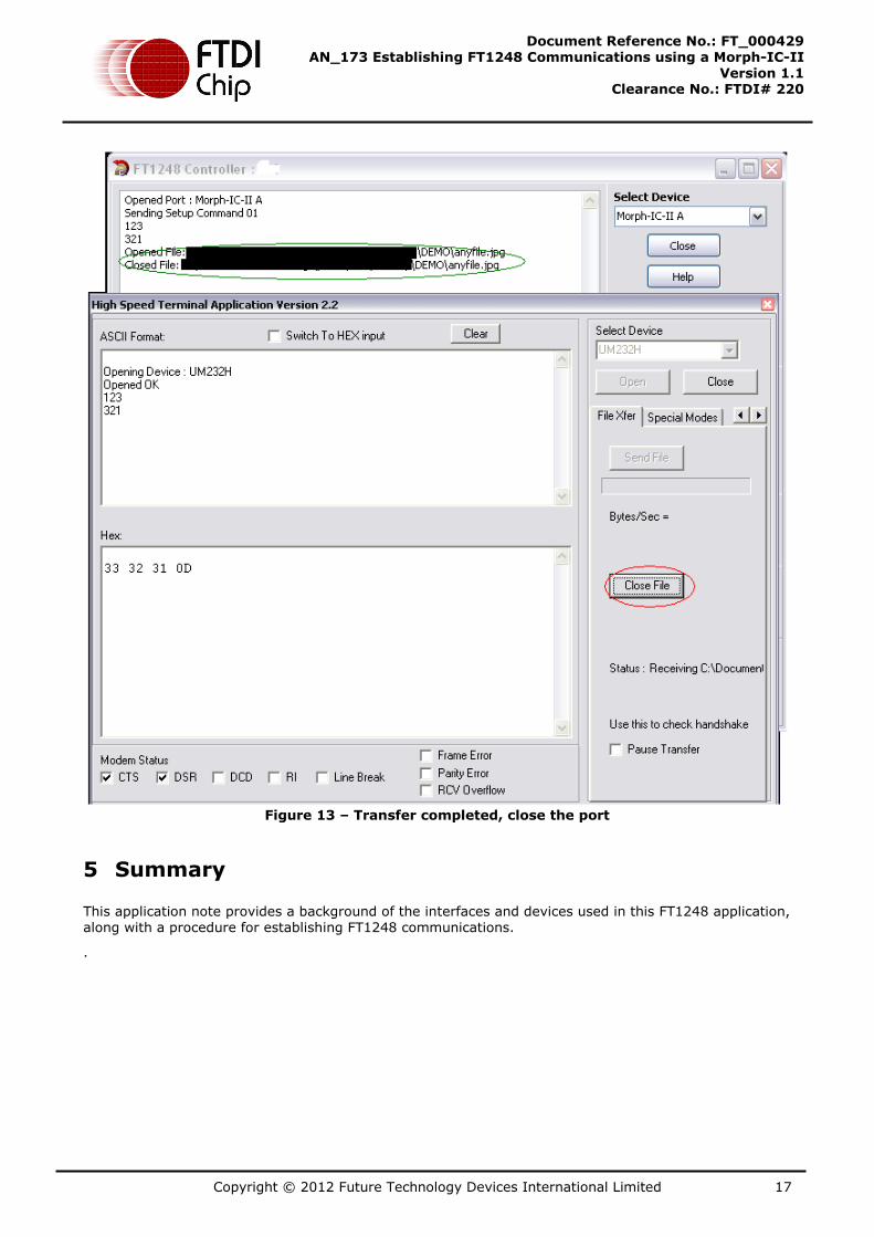
Once the file has transferred the FT1248 Controller will automatically close the file, the transferred file needs to be manually closed at the terminal.exe side. This step is illustrated in Figure 13. To verify the file has been transferred correctly open the received file to see if it appears to be normal.
Transferring a file from the UM232H to the Morph-IC-II will test how data transfers in the opposite direction. This is carried out in a similar way, where the FT1248 Controller sets the location and name of the received file and the terminal program sends the file.
Copyright © 2012 Future Technology Devices International Limited 17
Document Reference No.: FT_000429 AN_173 Establishing FT1248 Communications using a Morph-IC-II
Version 1.1 Clearance No.: FTDI# 220
Figure 13 – Transfer completed, close the port
5 Summary
This application note provides a background of the interfaces and devices used in this FT1248 application, along with a procedure for establishing FT1248 communications.
.

Copyright © 2012 Future Technology Devices International Limited 18
Document Reference No.: FT_000429 AN_173 Establishing FT1248 Communications using a Morph-IC-II
Version 1.1 Clearance No.: FTDI# 220
6 Contact Information
Head Office – Glasgow, UK
Future Technology Devices International Limited
Unit 1, 2 Seaward Place, Centurion Business Park
Glasgow G41 1HH
United Kingdom
Tel: +44 (0) 141 429 2777
Fax: +44 (0) 141 429 2758
E-mail (Sales) [email protected] E-mail (Support) [email protected] E-mail (General Enquiries) [email protected]
Branch Office – Hillsboro, Oregon, USA
Future Technology Devices International Limited (USA)
7235 NW Evergreen Parkway, Suite 600
Hillsboro, OR 97123-5803
USA
Tel: +1 (503) 547 0988
Fax: +1 (503) 547 0987
E-Mail (Sales) [email protected] E-Mail (Support) [email protected] E-Mail (General Enquiries) [email protected]
Branch Office – Taipei, Taiwan
Future Technology Devices International Limited (Taiwan)
2F, No. 516, Sec. 1, NeiHu Road
Taipei 114
Taiwan , R.O.C.
Tel: +886 (0) 2 8791 3570
Fax: +886 (0) 2 8791 3576
E-mail (Sales) [email protected]
E-mail (Support) [email protected]
E-mail (General Enquiries) [email protected]
Branch Office – Shanghai, China
Future Technology Devices International Limited (China)
Room 1103, No. 666 West Huaihai Road,
Shanghai, 200052
China
Tel: +86 21 62351596
Fax: +86 21 62351595
E-mail (Sales) [email protected] E-mail (Support) [email protected] E-mail (General Enquiries) [email protected]
Distributor and Sales Representatives
Please visit the Sales Network page of the FTDI Web site for the contact details of our distributor(s) and sales representative(s) in your country.
Legal Disclaimer:
System and equipment manufacturers and designers are responsible to ensure that their systems, and any Future Technology Devices International Ltd (FTDI) devices incorporated in their systems, meet all applicable safety, regulatory and system-level performance requirements. All application-related information in this document (including application descriptions, suggested FTDI devices and other materials) is provided for reference only. While FTDI has taken care to assure it is accurate, this information is subject to customer confirmation, and FTDI disclaims all liability for system designs and for
any applications assistance provided by FTDI. Use of FTDI devices in life support and/or safety applications is entirely at the user’s risk, and the user agrees to defend, indemnify and hold harmless FTDI from any and all damages, claims, suits or expense resulting from such use. This document is subject to change without notice. No freedom to use patents or other intellectual property rights is implied by the publication of this document. Neither the whole nor any part of the information contained in, or the product described in this document, may be adapted or reproduced in any material or electronic
form without the prior written consent of the copyright holder. Future Technology Devices International
Ltd, Unit 1, 2 Seaward Place, Centurion Business Park, Glasgow G41 1HH, United Kingdom. Scotland Registered Company Number: SC136640
Use of FTDI devices in life support and/or safety applications is entirely at the user’s risk, and the user agrees to defend, indemnify and hold harmless FTDI from any and all damages, claims, suits or expense resulting from such use.
Copyright © 2012 Future Technology Devices International Limited 19
Document Reference No.: FT_000429 AN_173 Establishing FT1248 Communications using a Morph-IC-II
Version 1.1 Clearance No.: FTDI# 220
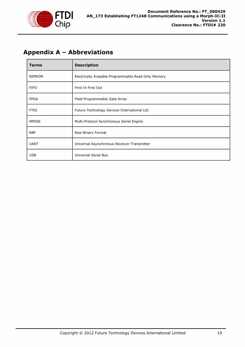
Appendix A – Abbreviations
Terms Description
EEPROM Electrically Erasable Programmable Read Only Memory
FIFO First In First Out
FPGA Field Programmable Gate Array
FTDI Future Technology Devices International Ltd.
MPSSE Multi-Protocol Synchronous Serial Engine
RBF Raw Binary Format
UART Universal Asynchronous Receiver Transmitter
USB Universal Serial Bus
Copyright © 2012 Future Technology Devices International Limited 20
Document Reference No.: FT_000429 AN_173 Establishing FT1248 Communications using a Morph-IC-II
Version 1.1 Clearance No.: FTDI# 220
Appendix B – References
“MorphIC_FT1248_master” download
http://www.ftdichip.com/Products/Files/MorphIC_FT1248_master.zip
“Morph-IC-II Applications and Utilities” download
http://www.ftdichip.com/Support/Utilities/MorphIC-II%20Package.zip
UM232H Datasheet
http://www.ftdichip.com/Support/Documents/DataSheets/Modules/DS_UM232H.pdf
Morph-IC-II
http://www.ftdichip.com/Support/Documents/DataSheets/Modules/DS_Morph-IC-II.pdf
FT_Prog
http://www.ftdichip.com/Resources/Utilities/FT_PROG.zip
D2xx Programmers Guide http://www.ftdichip.com/Documents/ProgramGuides/D2XX_Programmer's_Guide(FT_000071).pdf
Interfacing FT2232H device to SPI http://www.ftdichip.com/Projects/MPSSE/AN_114_FTDI_Hi_Speed_USB_To_SPI_Example.pdf
Recovery utility
http://www.ftdichip.com/Resources/Utilities/SPITest.zip
Quartus-II
http://www.altera.com/products/software/quartus-ii/web-edition/qts-we-index.html
AN_167 FT1248 Parallel Serial Interface Basics
http://www.ftdichip.com/Support/Documents/AppNotes/AN_167_FT1248_Parallel_Serial_Interface_Basics.pdf
Copyright © 2012 Future Technology Devices International Limited 21
Document Reference No.: FT_000429 AN_173 Establishing FT1248 Communications using a Morph-IC-II
Version 1.1 Clearance No.: FTDI# 220
Appendix C – Revision History
Revision Changes Date
1.0 First Issue 2011-09-12
1.1 Corrected Figure 4 – Morph-IC-II and FT232H wire scheme 2012-06-26
Updated contact information