Embed Size (px)
Citation preview
Neither the whole nor any part of the information contained in, or the product described in this manual, may be adapted or
reproduced in any material or electronic form without the prior written consent of the copyright holder. This product and its
documentation are supplied on an as-is basis and no warranty as to their suitability for any particular purpose is either made or
implied. Future Technology Devices International Ltd will not accept any claim for damages howsoever arising as a result of use or
failure of this product. Your statutory rights are not affected. This product or any variant of it is not intended for use in any
medical appliance, device or system in which the failure of the product might reasonably be expected to result in personal injury.
This document provides preliminary information that may be subject to change without notice. No freedom to use patents or other
intellectual property rights is implied by the publication of this document. Future Technology Devices International Ltd, Unit 1, 2
Seaward Place, Centurion Business Park, Glasgow G41 1HH United Kingdom. Scotland Registered Company Number: SC136640
Copyright © Bridgetek Limited 1
NerO Module Datasheet Datasheet Version 1.1
Document Reference No.: BRT_000043 Clearance No.: BRT#030
Future Technology Devices International
Limited
Datasheet
NerO Module
1 Introduction
The Nero is a reference design for an energy
efficient Arduino UNO compatible board based on the ATMEGA328 with the FTDI FT231X USB- UART, capable of operating at 5V with a full 1A while remaining cool to the touch
There are 3 type of modules for selection:
NerO-LP1, with 2.54mm pitch female header with long shield pins
NerO-SP1, with 2.54mm pitch female header with short shield pins
NerO-NP1, with spare shield pins but not mounted. (Provide long shield pins
externally.)
1.1 Features
16MHz ATmega328 32-pin TQFP package
microcontroller.
UNO R3 form factor
14 Digital I/O Pins (6 PWM outputs)
6 Analog Inputs
FTDI FT231XS USB UART interface
A Micro-B USB connects to PC connect and
communication.
VIN Input voltage - 7V to 20V ( 9V or 12V
recommended )
Hardware Reset button provided.
5V Switching regulator with 1A output current
CE and FCC certified
Optiboot bootloader preloaded
Arduino Software (IDE) and UNO library
compatible,
Arduino shield compatible
FTDI Shield available soon
Copyright © Bridgetek Limited 2
NerO Module Datasheet Datasheet Version 1.1
Document Reference No.: BRT_000043 Clearance No.: BRT#030
2 Ordering Information
Part No. Description
NerO-LP1 Arduino UNO compatible board based on the FTDI FT231X USB UART.
Power supply delivers 5V at a full 1A without overheating. Long shield pins.
NerO-SP1 Arduino UNO compatible board based on the FTDI FT231X USB UART. Power supply delivers 5V at a full 1A without overheating. Short shield pins.
NerO-NP1
Arduino UNO compatible board based on the FTDI FT231X USB UART.
Power supply delivers 5V at a full 1A without overheating. Spare shield pins (not mounted and provide long shield pins on the package.)
Copyright © Bridgetek Limited 3
NerO Module Datasheet Datasheet Version 1.1
Document Reference No.: BRT_000043 Clearance No.: BRT#030
3 Program Support
The open-source Arduino Software (IDE) can be downloaded at Arduino website. Visit Arduino’s
website at https://www.arduino.cc/en/Main/Software for more information. The Arduino IDE programming user guide gives the instruction of software development.
The programmer utility – In case to customize the module descriptions and other parameters, FT_Prog is provided for FT231XS by FTDI. Visit FTDI’s website at http://www.ftdichip.com/Support/Utilities.htm for more information.
Copyright © Bridgetek Limited 4
NerO Module Datasheet Datasheet Version 1.1
Document Reference No.: BRT_000043 Clearance No.: BRT#030
Table of Contents
1 Introduction .................................................................... 1
1.1 Features .................................................................................... 1
2 Ordering Information ...................................................... 2
3 Program Support ............................................................. 3
4 Board Layout ................................................................... 5
4.1 Power Supply ............................................................................ 6
4.2 Micro-controller ........................................................................ 7
4.3 USB to Serial UART Converter ................................................... 8
4.4 External I/O Port ...................................................................... 8
5 Devices Characteristics and Ratings .............................. 11
5.1 Electrical Parameters .............................................................. 11
6 Board Schematic ........................................................... 12
7 Block Diagram ............................................................... 13
8 Mechanical Dimensions ................................................. 14
8.1 NerO PCB Dimensions ............................................................. 14
9 Contact Information ...................................................... 15
Appendix A - References .................................................... 16
Document References ..................................................................... 16
Acronyms and Abbreviations ........................................................... 16
Appendix B – List of Figures and Tables ............................. 17
List of Tables ................................................................................... 17
List of Figures ................................................................................. 17
Appendix C – Revision History ........................................... 18
Copyright © Bridgetek Limited 5
NerO Module Datasheet Datasheet Version 1.1
Document Reference No.: BRT_000043 Clearance No.: BRT#030
4 Board Layout
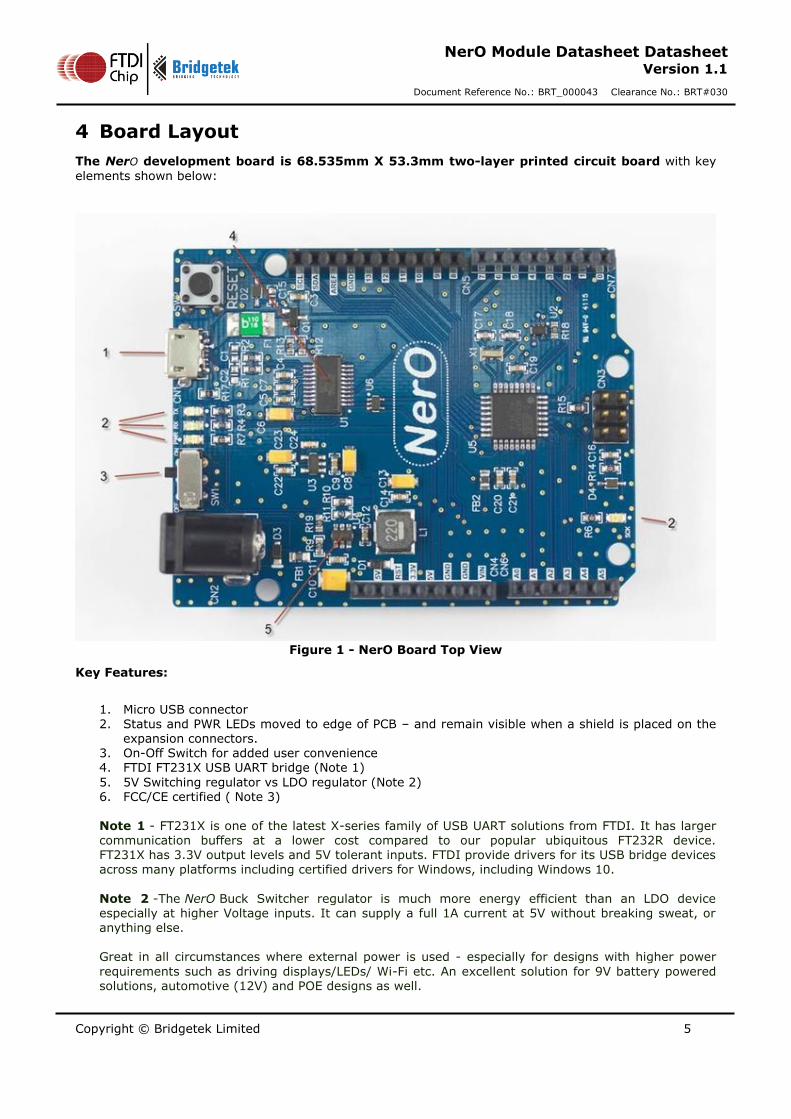
The NerO development board is 68.535mm X 53.3mm two-layer printed circuit board with key
elements shown below:
Figure 1 - NerO Board Top View
Key Features:
1. Micro USB connector 2. Status and PWR LEDs moved to edge of PCB – and remain visible when a shield is placed on the
expansion connectors. 3. On-Off Switch for added user convenience 4. FTDI FT231X USB UART bridge (Note 1)
5. 5V Switching regulator vs LDO regulator (Note 2) 6. FCC/CE certified ( Note 3) Note 1 - FT231X is one of the latest X-series family of USB UART solutions from FTDI. It has larger communication buffers at a lower cost compared to our popular ubiquitous FT232R device. FT231X has 3.3V output levels and 5V tolerant inputs. FTDI provide drivers for its USB bridge devices across many platforms including certified drivers for Windows, including Windows 10.
Note 2 -The NerO Buck Switcher regulator is much more energy efficient than an LDO device especially at higher Voltage inputs. It can supply a full 1A current at 5V without breaking sweat, or anything else. Great in all circumstances where external power is used - especially for designs with higher power
requirements such as driving displays/LEDs/ Wi-Fi etc. An excellent solution for 9V battery powered solutions, automotive (12V) and POE designs as well.
Copyright © Bridgetek Limited 6
NerO Module Datasheet Datasheet Version 1.1
Document Reference No.: BRT_000043 Clearance No.: BRT#030
Note 3 - NerO is FCC/CE certified as is the original UNO, and so is suitable for commercial applications as well as hobbyist/maker projects
4.1 Power Supply
The NerO board provides alternative power supply sources with an On/Off Switch (SW1):
1. 9V or 12V DC supply, 2.1mm power DC Jack Connector CN2.
The 9V or 12V option is recommended in designs using the NerO to supply power to Arduino shields
SW1 – On/Off Switch
Switch Mode DC
ON
OFF ×
Table 1 - Switch Mode
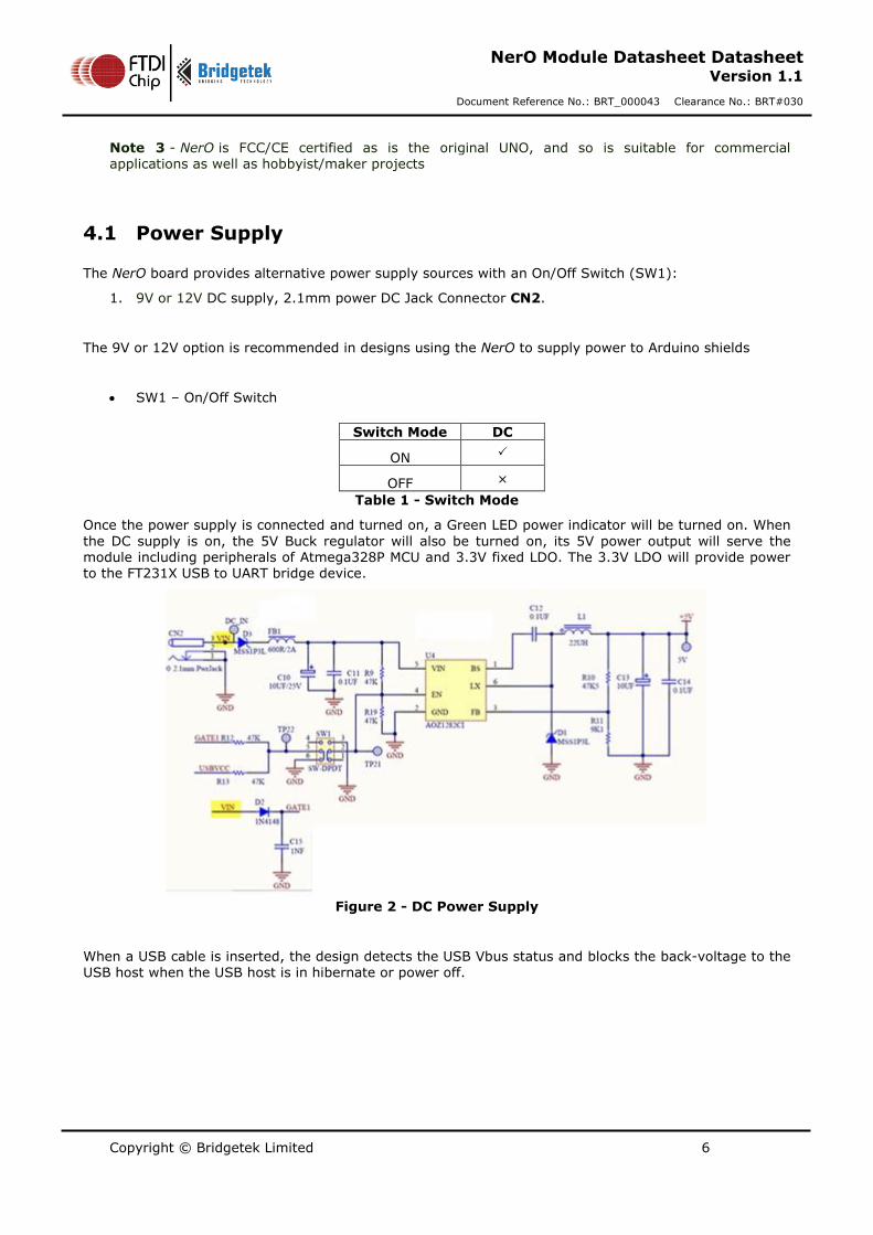
Once the power supply is connected and turned on, a Green LED power indicator will be turned on. When
the DC supply is on, the 5V Buck regulator will also be turned on, its 5V power output will serve the module including peripherals of Atmega328P MCU and 3.3V fixed LDO. The 3.3V LDO will provide power to the FT231X USB to UART bridge device.
Figure 2 - DC Power Supply
When a USB cable is inserted, the design detects the USB Vbus status and blocks the back-voltage to the
USB host when the USB host is in hibernate or power off.
Copyright © Bridgetek Limited 7
NerO Module Datasheet Datasheet Version 1.1
Document Reference No.: BRT_000043 Clearance No.: BRT#030
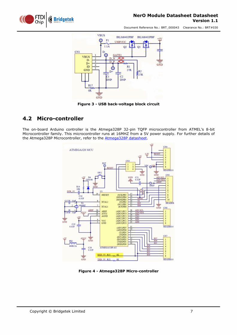
Figure 3 - USB back-voltage block circuit
4.2 Micro-controller
The on-board Arduino controller is the Atmega328P 32-pin TQFP microcontroller from ATMEL’s 8-bit Microcontroller family. This microcontroller runs at 16MHZ from a 5V power supply. For further details of the Atmega328P Microcontroller, refer to the Atmega328P datasheet.
Figure 4 - Atmega328P Micro-controller

Copyright © Bridgetek Limited 8
NerO Module Datasheet Datasheet Version 1.1
Document Reference No.: BRT_000043 Clearance No.: BRT#030
4.3 USB to Serial UART Converter
Loading firmware into the ARDUINO is done over USB via the FT231XS 20 Pin SSOP USB to serial UART converter. For detail of the FT231XS, refer to the FT231XS datasheet. Two Status LED connected to the
FT231XS provide visual indication of RX/TX traffic on the device UART port.
LEDs Colour Description
TX Yellow Blinking – Transmitting
RX Yellow Blinking – Receiving
Table 2- LED Status
Figure 5 - FT231XS USB to Serial Converter
4.4 External I/O Port
There are 14 digital IO pins provided on CN5(1X 10 pins) and CN7(1X 8 pins), 2.54mm pitch female header.
There are 6 Analog inputs provided on CN6(1X 6 pins), 2.54mm female header.
CN4(1X 8 pins) 2.54mm female header provides access to supply or draw power to/from the board.
Table 3 - Pin Mapping of CN5 lists the entire pin mapping on CN5
Pin No Pin Name Description
1 SCL I2C Serial Bus, clock line
Copyright © Bridgetek Limited 9
NerO Module Datasheet Datasheet Version 1.1
Document Reference No.: BRT_000043 Clearance No.: BRT#030
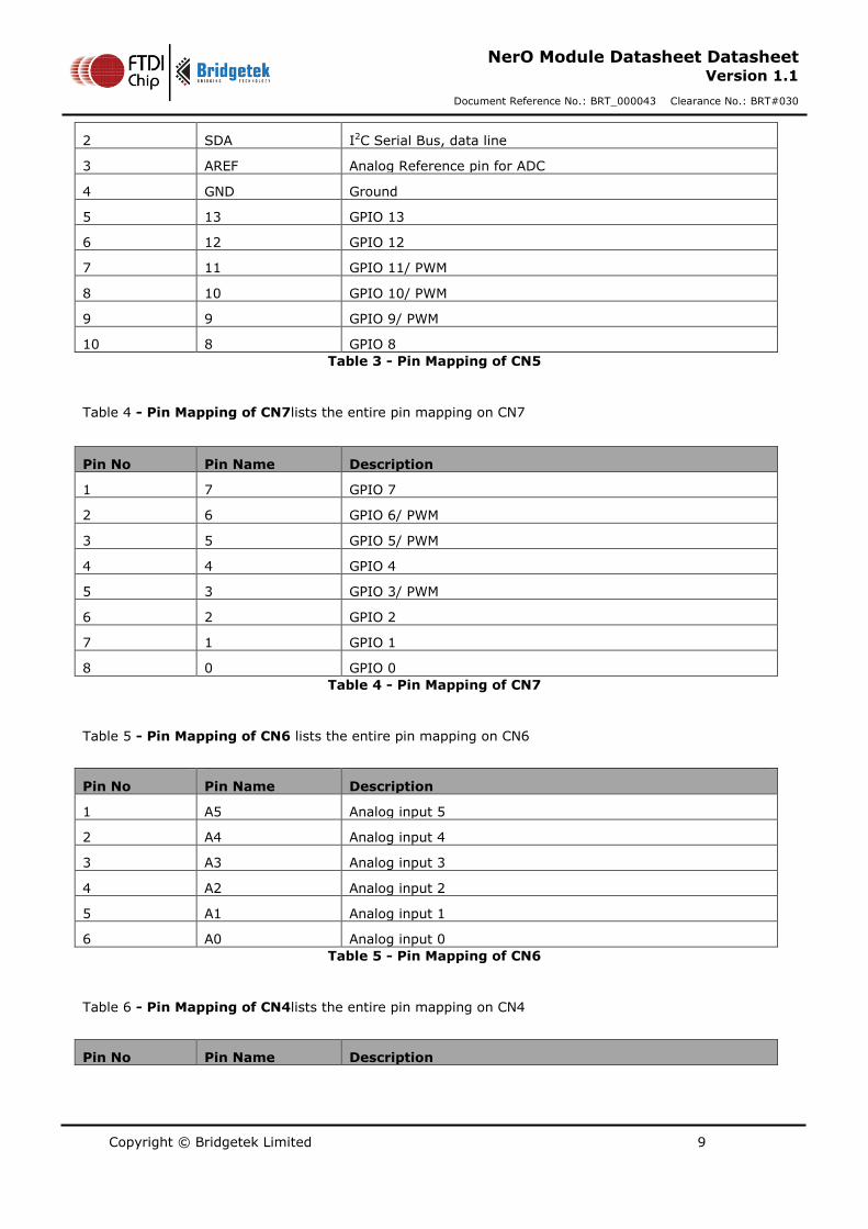
2 SDA I2C Serial Bus, data line
3 AREF Analog Reference pin for ADC
4 GND Ground
5 13 GPIO 13
6 12 GPIO 12
7 11 GPIO 11/ PWM
8 10 GPIO 10/ PWM
9 9 GPIO 9/ PWM
10 8 GPIO 8
Table 3 - Pin Mapping of CN5
Table 4 - Pin Mapping of CN7lists the entire pin mapping on CN7
Pin No Pin Name Description
1 7 GPIO 7
2 6 GPIO 6/ PWM
3 5 GPIO 5/ PWM
4 4 GPIO 4
5 3 GPIO 3/ PWM
6 2 GPIO 2
7 1 GPIO 1
8 0 GPIO 0
Table 4 - Pin Mapping of CN7
Table 5 - Pin Mapping of CN6 lists the entire pin mapping on CN6
Pin No Pin Name Description
1 A5 Analog input 5
2 A4 Analog input 4
3 A3 Analog input 3
4 A2 Analog input 2
5 A1 Analog input 1
6 A0 Analog input 0
Table 5 - Pin Mapping of CN6
Table 6 - Pin Mapping of CN4lists the entire pin mapping on CN4
Pin No Pin Name Description
Copyright © Bridgetek Limited 10
NerO Module Datasheet Datasheet Version 1.1
Document Reference No.: BRT_000043 Clearance No.: BRT#030
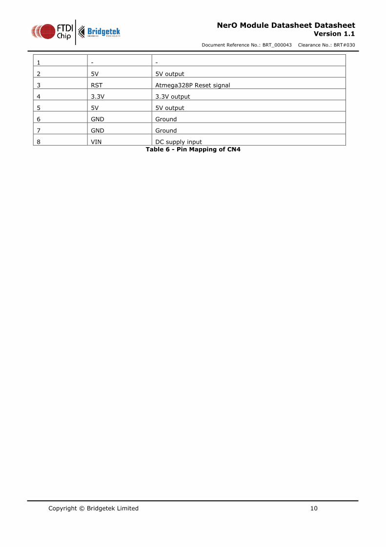
1 - -
2 5V 5V output
3 RST Atmega328P Reset signal
4 3.3V 3.3V output
5 5V 5V output
6 GND Ground
7 GND Ground
8 VIN DC supply input
Table 6 - Pin Mapping of CN4
Copyright © Bridgetek Limited 11
NerO Module Datasheet Datasheet Version 1.1
Document Reference No.: BRT_000043 Clearance No.: BRT#030
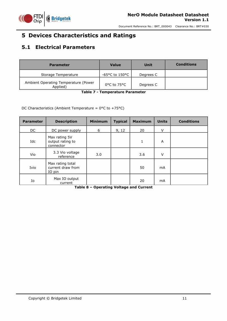
5 Devices Characteristics and Ratings
5.1 Electrical Parameters
Parameter Value Unit Conditions
Storage Temperature -65°C to 150°C Degrees C
Ambient Operating Temperature (Power Applied)
0°C to 75°C Degrees C
Table 7 - Temperature Parameter
DC Characteristics (Ambient Temperature = 0°C to +75°C)
Parameter Description Minimum Typical Maximum Units Conditions
DC DC power supply 6 9, 12 20 V
Idc
Max rating 5V
output rating to connector
1 A
Vio 3.3 Vio voltage
reference 3.0 3.6 V
Ivio Max rating total current draw from IO pin
50 mA
Io Max IO output
current 20 mA
Table 8 – Operating Voltage and Current

Copyright © Bridgetek Limited 12
NerO Module Datasheet Datasheet Version 1.1
Document Reference No.: BRT_000043 Clearance No.: BRT#030
6 Board Schematic
Figure 6 – NerO Schematic
Copyright © Bridgetek Limited 13
NerO Module Datasheet Datasheet Version 1.1
Document Reference No.: BRT_000043 Clearance No.: BRT#030
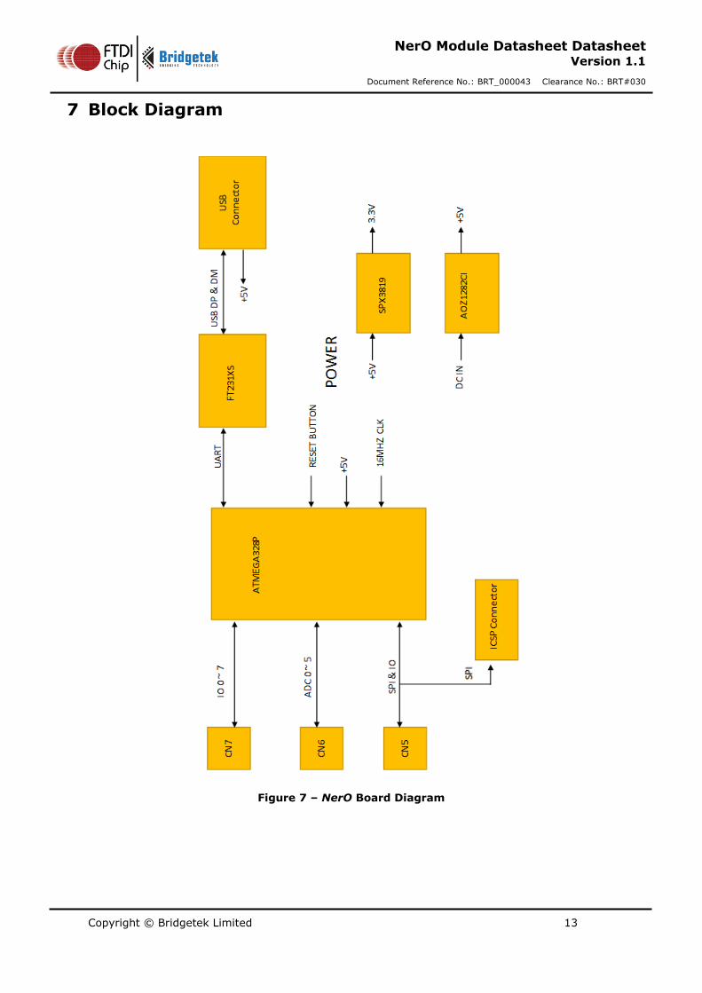
7 Block Diagram
Figure 7 – NerO Board Diagram
Copyright © Bridgetek Limited 14
NerO Module Datasheet Datasheet Version 1.1
Document Reference No.: BRT_000043 Clearance No.: BRT#030
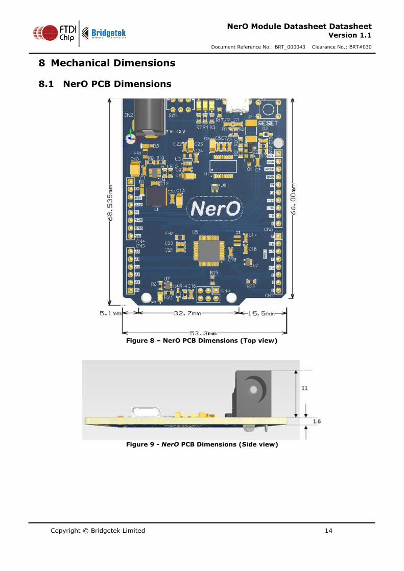
8 Mechanical Dimensions
8.1 NerO PCB Dimensions
Figure 8 – NerO PCB Dimensions (Top view)
Figure 9 - NerO PCB Dimensions (Side view)

Copyright © Bridgetek Limited 15
NerO Module Datasheet Datasheet Version 1.1
Document Reference No.: BRT_000043 Clearance No.: BRT#030
9 Contact Information
Head Quarters – Singapore Branch Office – Taipei, Taiwan
Bridgetek Pte Ltd 178 Paya Lebar Road, #07-03 Singapore 409030 Tel: +65 6547 4827 Fax: +65 6841 6071
Bridgetek Pte Ltd, Taiwan Branch 2 Floor, No. 516, Sec. 1, Nei Hu Road, Nei Hu District Taipei 114 Taiwan, R.O.C. Tel: +886 (2) 8797 5691 Fax: +886 (2) 8751 9737
E-mail (Sales) [email protected] E-mail (Sales) [email protected] E-mail (Support) [email protected] E-mail (Support) [email protected]
Branch Office - Glasgow, United Kingdom Branch Office – Vietnam
Bridgetek Pte. Ltd. Unit 1, 2 Seaward Place, Centurion Business Park Glasgow G41 1HH United Kingdom Tel: +44 (0) 141 429 2777 Fax: +44 (0) 141 429 2758
Bridgetek VietNam Company Limited Lutaco Tower Building, 5th Floor, 173A Nguyen Van Troi, Ward 11, Phu Nhuan District, Ho Chi Minh City, Vietnam Tel : 08 38453222 Fax : 08 38455222
E-mail (Sales) [email protected] E-mail (Sales) [email protected] E-mail (Support) [email protected] E-mail (Support) [email protected]
Web Site
http://brtchip.com/
Distributor and Sales Representatives
Please visit the Sales Network page of the Bridgetek Web site for the contact details of our distributor(s) and sales
representative(s) in your country.
System and equipment manufacturers and designers are responsible to ensure that their systems, and any Future Technology Devices
International Ltd (FTDI) devices incorporated in their systems, meet all applicable safety, regulatory and system-level performance
requirements. All application-related information in this document (including application descriptions, suggested FTDI devices and other materials) is provided for reference only. While FTDI has taken care to assure it is accurate, this information is subject to customer
confirmation, and FTDI disclaims all liability for system designs and for any applications assistance provided by FTDI. Use of FTDI
devices in life support and/or safety applications is entirely at the user’s risk, and the user agrees to defend, indemnify and hold
harmless FTDI from any and all damages, claims, suits or expense resulting from such use. This document is subject to change without
notice. No freedom to use patents or other intellectual property rights is implied by the publication of this document. Neither the whole
nor any part of the information contained in, or the product described in this document, may be adapted or reproduced in any material
or electronic form without the prior written consent of the copyright holder. Future Technology Devices International Ltd, Unit 1, 2
Seaward Place, Centurion Business Park, Glasgow G41 1HH, United Kingdom. Scotland Registered Company Number: SC136640
Copyright © Bridgetek Limited 16
NerO Module Datasheet Datasheet Version 1.1
Document Reference No.: BRT_000043 Clearance No.: BRT#030
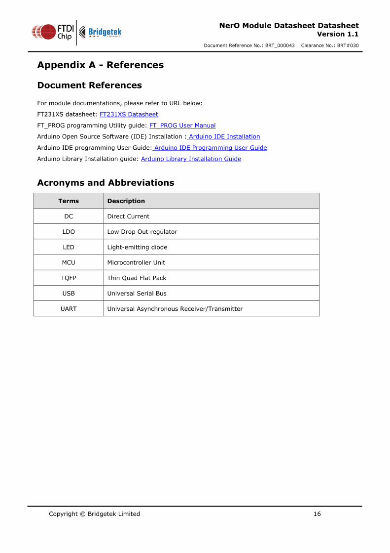
Appendix A - References
Document References
For module documentations, please refer to URL below:
FT231XS datasheet: FT231XS Datasheet
FT_PROG programming Utility guide: FT_PROG User Manual
Arduino Open Source Software (IDE) Installation : Arduino IDE Installation
Arduino IDE programming User Guide: Arduino IDE Programming User Guide
Arduino Library Installation guide: Arduino Library Installation Guide
Acronyms and Abbreviations
Terms Description
DC Direct Current
LDO Low Drop Out regulator
LED Light-emitting diode
MCU Microcontroller Unit
TQFP Thin Quad Flat Pack
USB Universal Serial Bus
UART Universal Asynchronous Receiver/Transmitter
Copyright © Bridgetek Limited 17
NerO Module Datasheet Datasheet Version 1.1
Document Reference No.: BRT_000043 Clearance No.: BRT#030
Appendix B – List of Figures and Tables
List of Tables
Table 1 - Switch Mode ................................................................................................................... 6
Table 2- LED Status ...................................................................................................................... 8
Table 3 - Pin Mapping of CN5 ......................................................................................................... 9
Table 4 - Pin Mapping of CN7 ......................................................................................................... 9
Table 5 - Pin Mapping of CN6 ......................................................................................................... 9
Table 6 - Pin Mapping of CN4 ....................................................................................................... 10
Table 7 - Temperature Parameter ................................................................................................. 11
Table 8 – Operating Voltage and Current ....................................................................................... 11
List of Figures
Figure 1 - NerO Board Top View ..................................................................................................... 5
Figure 2 - DC Power Supply ........................................................................................................... 6
Figure 3 - USB back-voltage block circuit ......................................................................................... 7
Figure 4 - Atmega328P Micro-controller ........................................................................................... 7
Figure 5 - FT231XS USB to Serial Converter ..................................................................................... 8
Figure 6 – NerO Schematic .......................................................................................................... 12
Figure 7 – NerO Board Diagram .................................................................................................... 13
Figure 8 – NerO PCB Dimensions (Top view) .................................................................................. 14
Figure 9 - NerO PCB Dimensions (Side view) .................................................................................. 14
Copyright © Bridgetek Limited 18
NerO Module Datasheet Datasheet Version 1.1
Document Reference No.: BRT_000043 Clearance No.: BRT#030
Appendix C – Revision History
Document Title: NerO Module Datasheet Datasheet
Document Reference No.: BRT_000043
Clearance No.: BRT#030
Product Page: http://brtchip.com/product
Document Feedback: Send Feedback
Revision Changes Date
Version 1.0 Initial Release 2016-02-01
Version 1.1
Dual branding to reflect the migration of the product to the Bridgetek name – logo changed, copyright changed, contact information changed
2016-09-16


![T..TQF P +F.FUT+ G+]WU TC ®T FM. PF.É UT..TQFP 3]C WM++ ... · p FeM] G]CiP]3 UT..TQF R {wPj ozXU htc UPj P lit cP VPz zgi Xhtthrdgm} VM MCiF.M ] C T FM. P U CCM. UT..TQFP PM ®T](https://img.pdfslide.us/doc/110x75/5f7b0e44164369302f35fe90/ttqf-p-ffut-gwu-tc-t-fm-pf-uttqfp-3c-wm-p-fem-gcip3-uttqf.jpg)


![ATF15xx-DK3 - Microchip Technologyww1.microchip.com/...CPLD-ATF15xx-DK3...UserGuide.pdf · Atmel 44-pin TQFP Socket Adapter Board (P/N: ATF15xx-DK3 ... [USER GUIDE] Atmel-3605C-CPLD-ATF15xx-DK3](https://img.pdfslide.us/doc/110x75/5ab4467c7f8b9a156d8bb310/atf15xx-dk3-microchip-44-pin-tqfp-socket-adapter-board-pn-atf15xx-dk3-user.jpg)